ABB, Robótica en 3P: Picking / Packing / Palletizing ... · Picking: nuevo robot ABB IRB 120
Upload
duonghuongCategory
view
224download
0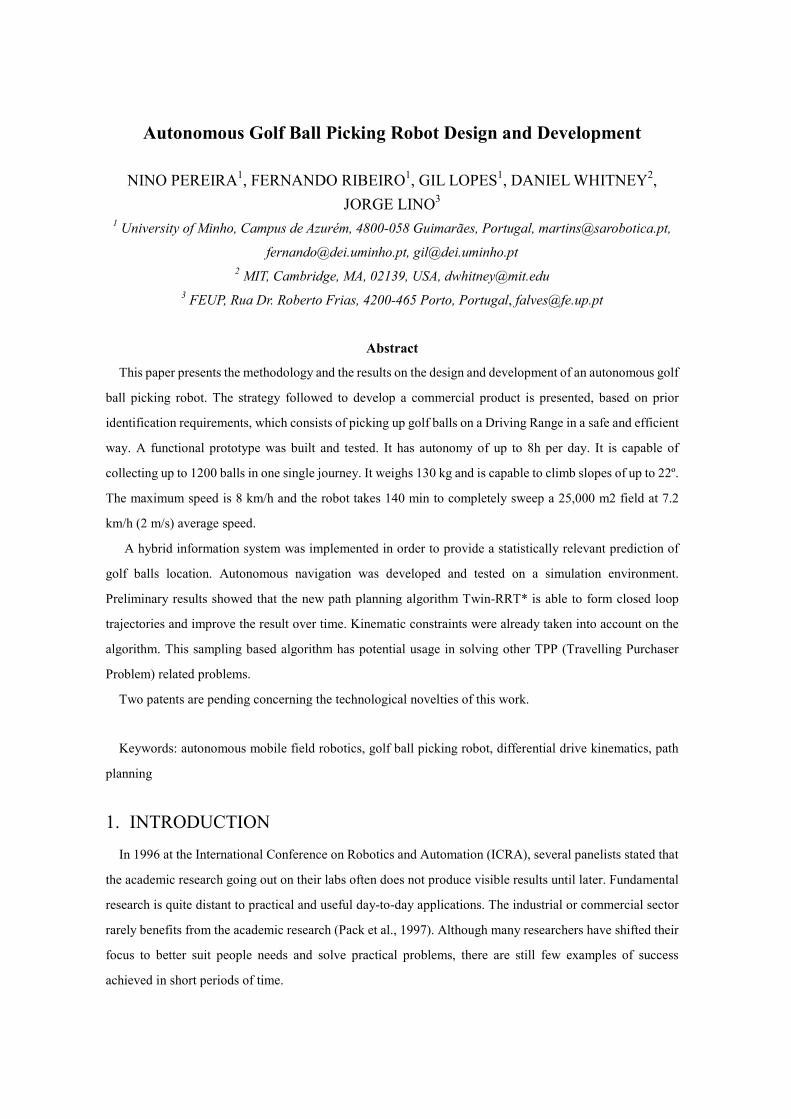
Autonomous Golf Ball Picking Robot Design and Development
NINO PEREIRA1, FERNANDO RIBEIRO1, GIL LOPES1, DANIEL WHITNEY2,
JORGE LINO3 1 University of Minho, Campus de Azurém, 4800-058 Guimarães, Portugal, [email protected],
[email protected], [email protected]
2 MIT, Cambridge, MA, 02139, USA, [email protected]
3 FEUP, Rua Dr. Roberto Frias, 4200-465 Porto, Portugal, [email protected]
Abstract
This paper presents the methodology and the results on the design and development of an autonomous golf
ball picking robot. The strategy followed to develop a commercial product is presented, based on prior
identification requirements, which consists of picking up golf balls on a Driving Range in a safe and efficient
way. A functional prototype was built and tested. It has autonomy of up to 8h per day. It is capable of
collecting up to 1200 balls in one single journey. It weighs 130 kg and is capable to climb slopes of up to 22º.
The maximum speed is 8 km/h and the robot takes 140 min to completely sweep a 25,000 m2 field at 7.2
km/h (2 m/s) average speed.
A hybrid information system was implemented in order to provide a statistically relevant prediction of
golf balls location. Autonomous navigation was developed and tested on a simulation environment.
Preliminary results showed that the new path planning algorithm Twin-RRT* is able to form closed loop
trajectories and improve the result over time. Kinematic constraints were already taken into account on the
algorithm. This sampling based algorithm has potential usage in solving other TPP (Travelling Purchaser
Problem) related problems.
Two patents are pending concerning the technological novelties of this work.
Keywords: autonomous mobile field robotics, golf ball picking robot, differential drive kinematics, path
planning
1. INTRODUCTION
In 1996 at the International Conference on Robotics and Automation (ICRA), several panelists stated that
the academic research going out on their labs often does not produce visible results until later. Fundamental
research is quite distant to practical and useful day-to-day applications. The industrial or commercial sector
rarely benefits from the academic research (Pack et al., 1997). Although many researchers have shifted their
focus to better suit people needs and solve practical problems, there are still few examples of success
achieved in short periods of time.
The project here presented is focused to deliver a commercial product in a very narrow time frame.
Researchers at the Automation and Robotics Laboratory of University of Minho have been developing
autonomous robots since 1998 (Machado et al., 1999b). Focusing on vision systems (Machado et al., 1999a,
Lima et al., 2001) and different mobile platforms (Ribeiro et al., 2004, Pacheco, 2008, Ribeiro, 2007b), the
group has contributed to improve people’s life by the use of autonomous or semi-autonomous mobile
platforms (Ribeiro, 2007a).
The idea of developing an autonomous mobile robot which could collect golf balls came from the fact that
Driving Ranges accumulate over 10,000 balls per day and requires an intensive and tedious human labor
even when accomplished with the help of motorized devices (Pacheco, 2008). To perform such task a
successful device would have to be able to maintain clear a 25,000 m2 field, collecting about 10,000 balls per
day, avoiding obstacles and climbing slopes up to 20 degrees. It should operate autonomously and be
resistant to corrosion since it would be navigating on external environment. Additional to these requirements
the robot should also be efficient, maximizing the number of balls collected over the travelled distance. This
paper describes the research and development work carried out to develop a commercial robot that responds
to this ambitious goal.
First, a detailed problem analysis and product development strategy is presented. The list of requirements
and technical specifications is established. The following section introduces the final concept that meets the
identified requirements and describes the methods to validate the hardware and functional behavior.
Afterwards, autonomous navigation simulations results and field test performance evaluation of the
industrial prototype are described. Finally, the main conclusions and further development directions are
presented.
2. PROBLEM ANALYSIS AND PRODUCT DEVELOPMENT
A set of milestones (Fig. 1Fig. 1) was established following the ideas of the product development process
proposed by Ulrich and Eppinger (Ulrich and Eppinger, 2004). The project was subdivided into two main
phases. Phase I comprises the correct identification of the need, the specifications of technical requirements,
the concept generations and the final concept selection. Phase II involves structural (hardware) and
functional validation, prototyping and field tests as depicted in Fig. 1.
2.1. The Need
In golf practice fields, the main requirement consists of
players. This need leads to the next one, which is preventing the ball dispensing machine from
empty, and consequently there is the need for some method, human or mechanical, to constantly
replenish the machine by picking up the golf balls and put them back into the dispensing machine (
Fig. 2).
Fig.
2.2. State of the Art
2.2.1. Traditional means
The golf ball picking task is, in many cases, performed by a worker, carrying
2008). Such work is considered to be tedious and causes many health problems related to back pain
Looze et al., 1995).
Even when it is performed with the help of mechanical devices, such as carts, or trolleys, which may
Balls are fed into the dispensing machine
Fig. 1 - Project Milestones
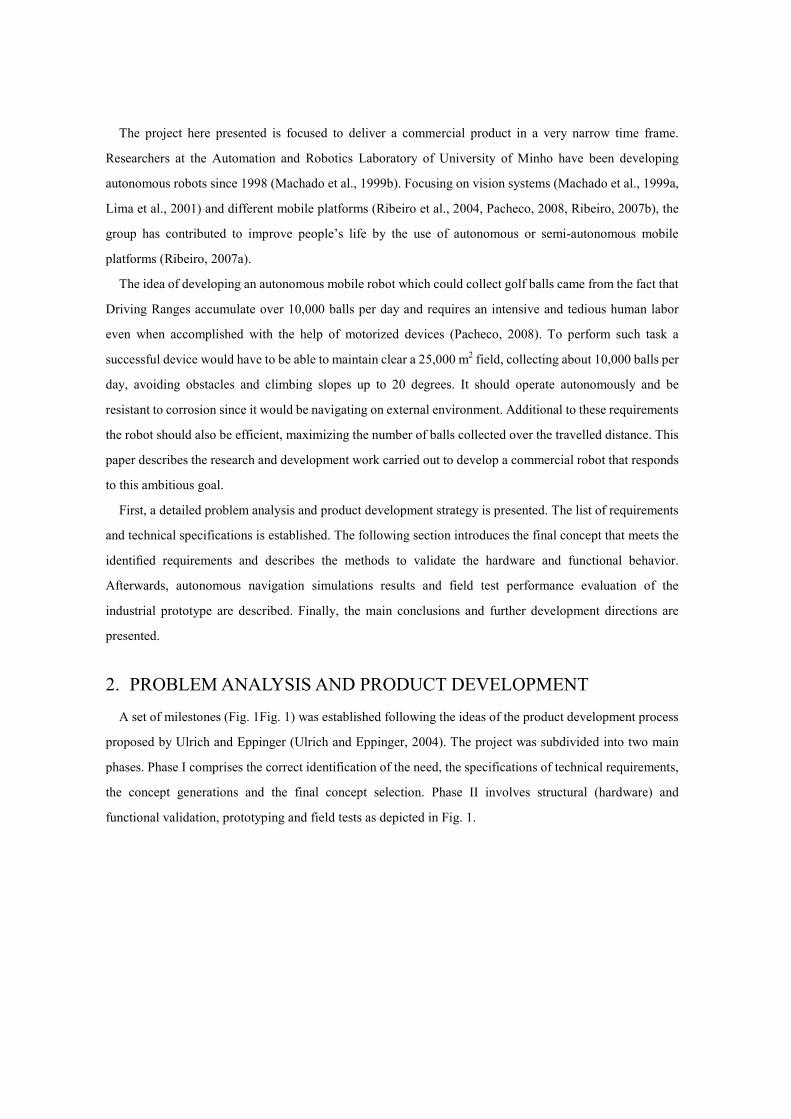
In golf practice fields, the main requirement consists of always guaranteeing balls availability for
players. This need leads to the next one, which is preventing the ball dispensing machine from
there is the need for some method, human or mechanical, to constantly
picking up the golf balls and put them back into the dispensing machine (
2
Fig. 2 - Golf ball cycle on a golf practice field
The golf ball picking task is, in many cases, performed by a worker, carrying just a basket
. Such work is considered to be tedious and causes many health problems related to back pain
Even when it is performed with the help of mechanical devices, such as carts, or trolleys, which may
Player shoots the ball
Balls sit on the field
Balls are picked up
Balls are fed into the dispensing machine
Players get balls from the machine
guaranteeing balls availability for
players. This need leads to the next one, which is preventing the ball dispensing machine from being
there is the need for some method, human or mechanical, to constantly
picking up the golf balls and put them back into the dispensing machine (Fig.
just a basket (Pacheco,
. Such work is considered to be tedious and causes many health problems related to back pain (De
Even when it is performed with the help of mechanical devices, such as carts, or trolleys, which may
improve the efficiency, they also require a big effort and still produce significant fatigue.
2.2.2. Buggy Solutions
The buggy solution is adopted as a more effective way to collect the golf balls. Relatively fast collecting
rates are achieved (4,000 balls/hour) and high capacity baskets (1,800 balls) are used. Nevertheless, they are
also human operated and require a significant initial investment. This is a problem because on one hand,
requires a worker to operate the machine which has a higher cost on human labor, and on the other hand, for
low usage rates, it is significantly more expensive taking into account the maintenance cost/operation time
ratio. Furthermore, the buggy needs parking space which has an additional cost.
2.2.3. Autonomous and Semi-autonomous devices
Researchers are already engaged on finding new approaches that could improve the golf ball picking task
(Ming-Shyan Wang, 2006, Pacheco, 2008, Sun-Li et al., 2005). Some use vision systems to find and pursuit
the golf balls (Sun-Li et al., 2005, Pacheco, 2008). Others use hand based movements to drive robots on the
field (Ming-Shyan Wang, 2006). As pointed out before, the need for dedicated and specialized vehicles to
pick up golf balls is becoming a must (Ming-Shyan Wang, 2006) to reduce overall costs and to decrease the
risk and health problems for humans.
There is an autonomous robot available in the market which aims to do this task in a simple manner
(Automation, 2011). It moves randomly within a wire limited perimeter and collects all the balls that appear
on its way. This robot has a 400 balls capacity container, weighs about 65 kg and operates at speeds up to 3.6
km/hour.
Vision systems often require an exhaustive and delicate calibration process (Yang et al., 2009, Li and
Chen, 2003), however, on external environments, this can be a major problem. Light variations, rain and dirt
can severely affect the vision systems (Jinwei et al., 2009). Direct human commands such as gestures, voice
commands, keyboard or touch screen inputs are all important machine interfaces which have been widely
used. Nevertheless, being autonomous, means to be able to operate without direct orders at all times (Wada,
2009).
2.3. Technical Specifications
A panel of 12 experts assisted the establishment of the requirements list. The developed solution
considered some constraints which were established following the feedback from the Portuguese Golf
Federation, including golf associations and golf course managers in a total of 12 persons. The main
constraints were: final price lower than 12,000€; collecting rate of about 10,000 balls/day; robot cover
material resistant to ball impact, oxidation and corrosion.
To meet the initial constraints, a list of target technical specifications was established and ranked
according to its relative importance (Table I). The metric unit and target value is shown where applicable.
Some of these metrics are subjective and should be later evaluated by users or observation.
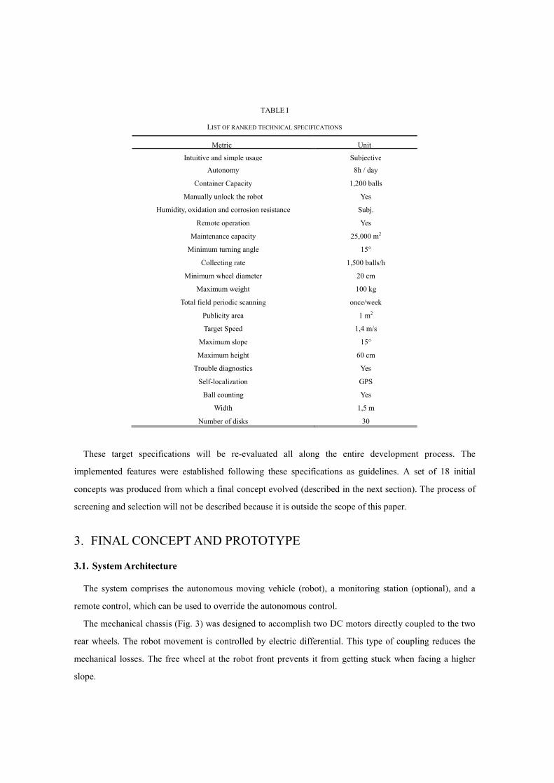
TABLE I
LIST OF RANKED TECHNICAL SPECIFICATIONS
Metric Unit
Intuitive and simple usage Subjective
Autonomy 8h / day
Container Capacity 1,200 balls
Manually unlock the robot Yes
Humidity, oxidation and corrosion resistance Subj.
Remote operation Yes
Maintenance capacity 25,000 m2
Minimum turning angle 15°
Collecting rate 1,500 balls/h
Minimum wheel diameter 20 cm
Maximum weight 100 kg
Total field periodic scanning once/week
Publicity area 1 m2
Target Speed 1,4 m/s
Maximum slope 15°
Maximum height 60 cm
Trouble diagnostics Yes
Self-localization GPS
Ball counting Yes
Width 1,5 m
Number of disks 30
These target specifications will be re-evaluated all along the entire development process. The
implemented features were established following these specifications as guidelines. A set of 18 initial
concepts was produced from which a final concept evolved (described in the next section). The process of
screening and selection will not be described because it is outside the scope of this paper.
3. FINAL CONCEPT AND PROTOTYPE
3.1. System Architecture
The system comprises the autonomous moving vehicle (robot), a monitoring station (optional), and a
remote control, which can be used to override the autonomous control.
The mechanical chassis (Fig. 3) was designed to accomplish two DC motors directly coupled to the two
rear wheels. The robot movement is controlled by electric differential. This type of coupling reduces the
mechanical losses. The free wheel at the robot front prevents it from getting stuck when facing a higher
slope.
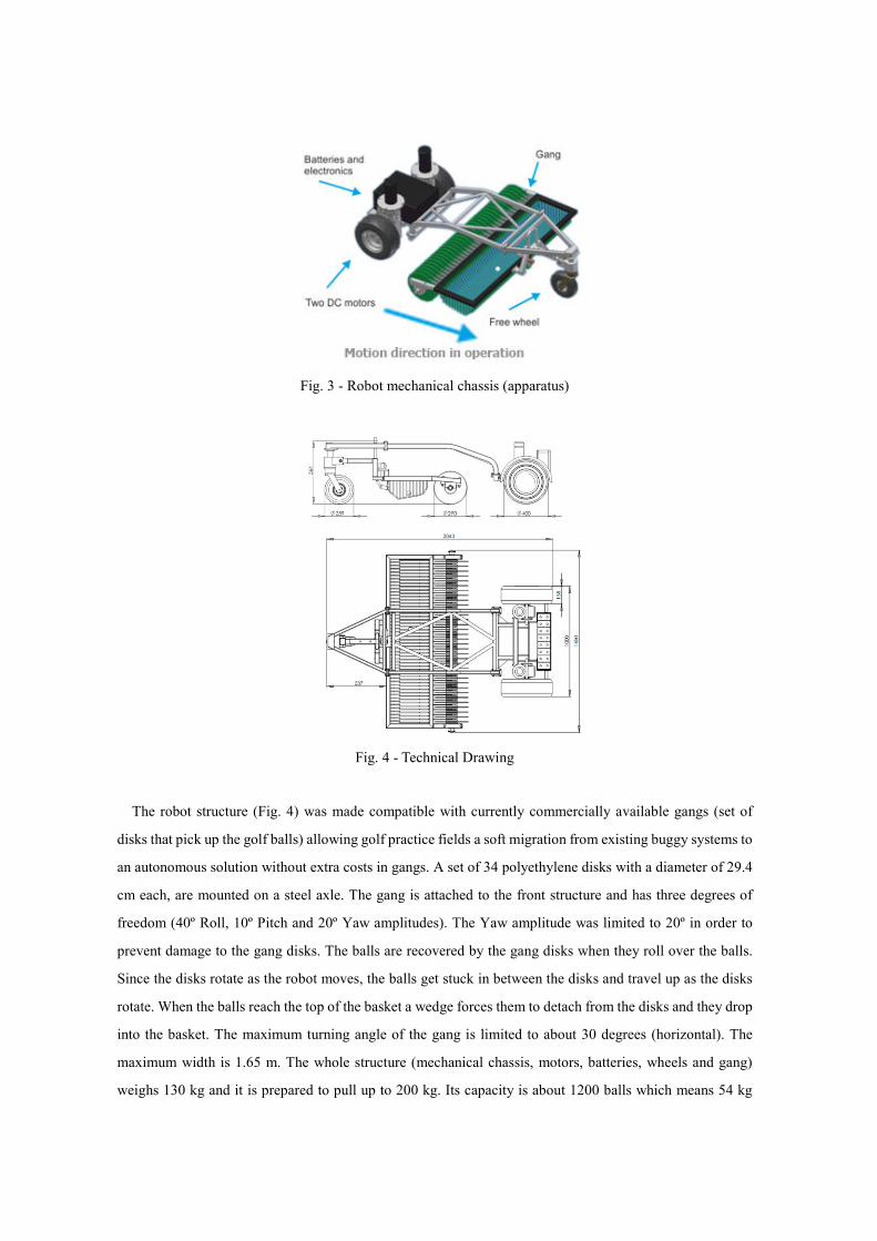
Fig. 3 - Robot mechanical chassis (apparatus)
Fig. 4 - Technical Drawing
The robot structure (Fig. 4) was made compatible with currently commercially available gangs (set of
disks that pick up the golf balls) allowing golf practice fields a soft migration from existing buggy systems to
an autonomous solution without extra costs in gangs. A set of 34 polyethylene disks with a diameter of 29.4
cm each, are mounted on a steel axle. The gang is attached to the front structure and has three degrees of
freedom (40º Roll, 10º Pitch and 20º Yaw amplitudes). The Yaw amplitude was limited to 20º in order to
prevent damage to the gang disks. The balls are recovered by the gang disks when they roll over the balls.
Since the disks rotate as the robot moves, the balls get stuck in between the disks and travel up as the disks
rotate. When the balls reach the top of the basket a wedge forces them to detach from the disks and they drop
into the basket. The maximum turning angle of the gang is limited to about 30 degrees (horizontal). The
maximum width is 1.65 m. The whole structure (mechanical chassis, motors, batteries, wheels and gang)
weighs 130 kg and it is prepared to pull up to 200 kg. Its capacity is about 1200 balls which means 54 kg
extra. The chassis is over the origina
its final version.
The monitoring station is an optional item. It provides information in real time about robot’s activity, with
a friendly interface to send commands to the robot and to receive feedback information.
configuration might be required at the installation procedure. It can be used to view or change some
configurations and eventually adjust some parameters in real time operation.
The remote control provides manual control of the robot, shou
operation gives the user full control of the robot movement.
communication using the Zigbee protocol. This
the operator when necessary.
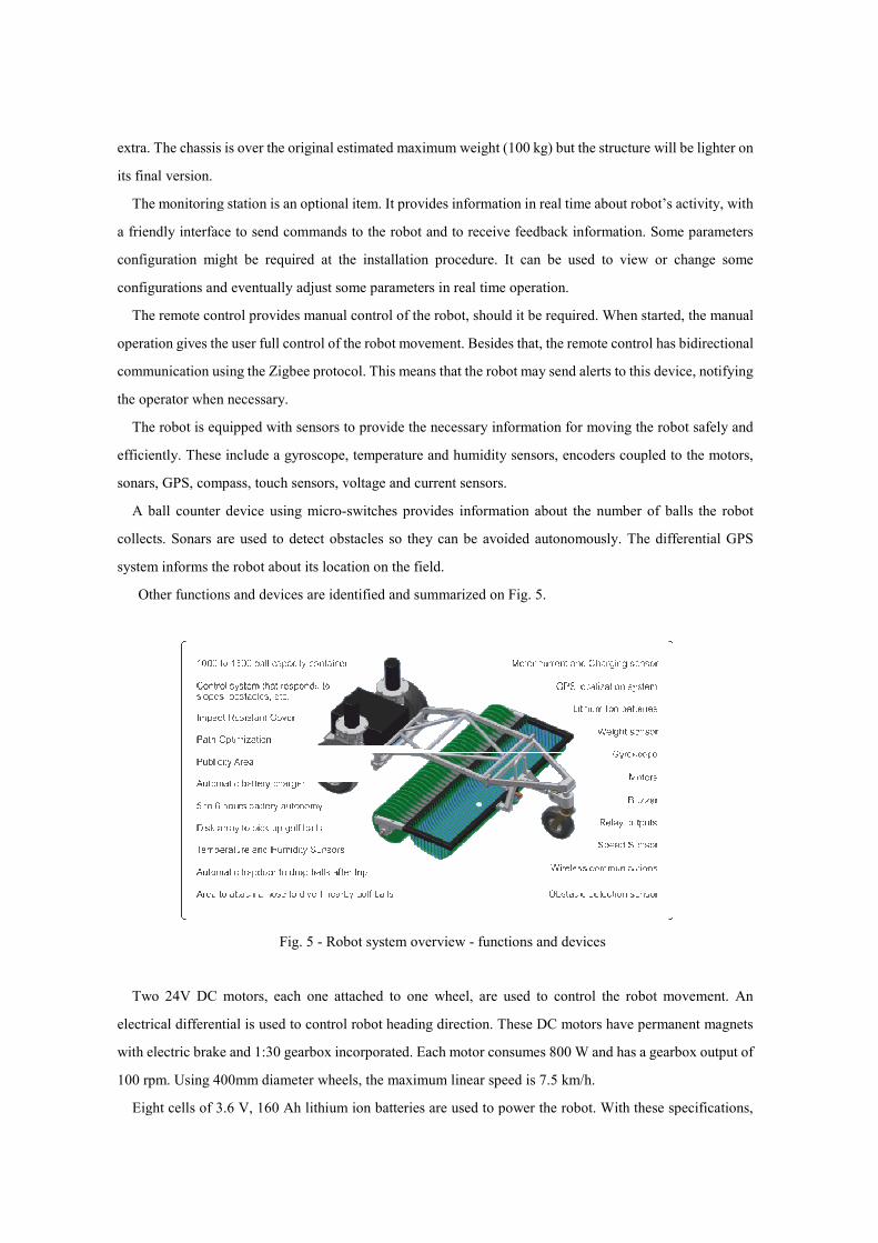
The robot is equipped with sensors to provide the necessary information for moving the robot safely and
efficiently. These include a gyroscope, temperature and humidity sensors, encoders coupled to the motors,
sonars, GPS, compass, touch sensors, voltage and current sensors.
A ball counter device using micro
collects. Sonars are used to detect obstacles so they can be avoided autonomously. The different
system informs the robot about its location on the field.
Other functions and devices are identified and summarized on
Fig. 5 -
Two 24V DC motors, each one attached to one wheel
electrical differential is used to control robot heading direction. These DC motors have permanent magnets
with electric brake and 1:30 gearbox incorporated. Each motor consu
100 rpm. Using 400mm diameter wheels, the maximum
Eight cells of 3.6 V, 160 Ah lithium ion batteries are used to power the robot. With these specifications,
The chassis is over the original estimated maximum weight (100 kg) but the structure will be
The monitoring station is an optional item. It provides information in real time about robot’s activity, with
a friendly interface to send commands to the robot and to receive feedback information.
configuration might be required at the installation procedure. It can be used to view or change some
configurations and eventually adjust some parameters in real time operation.
The remote control provides manual control of the robot, should it be required. When
operation gives the user full control of the robot movement. Besides that, the remote control has bidirectional
communication using the Zigbee protocol. This means that the robot may send alerts to this device
The robot is equipped with sensors to provide the necessary information for moving the robot safely and
efficiently. These include a gyroscope, temperature and humidity sensors, encoders coupled to the motors,
, GPS, compass, touch sensors, voltage and current sensors.
A ball counter device using micro-switches provides information about the number of balls the robot
. Sonars are used to detect obstacles so they can be avoided autonomously. The different
system informs the robot about its location on the field.
Other functions and devices are identified and summarized on Fig. 5.
- Robot system overview - functions and devices
Two 24V DC motors, each one attached to one wheel, are used to control the robot movement. An
electrical differential is used to control robot heading direction. These DC motors have permanent magnets
gearbox incorporated. Each motor consumes 800 W and has a gearbox output of
0mm diameter wheels, the maximum linear speed is 7.5 km/h.
Eight cells of 3.6 V, 160 Ah lithium ion batteries are used to power the robot. With these specifications,
g) but the structure will be lighter on
The monitoring station is an optional item. It provides information in real time about robot’s activity, with
a friendly interface to send commands to the robot and to receive feedback information. Some parameters
configuration might be required at the installation procedure. It can be used to view or change some
ld it be required. When started, the manual
Besides that, the remote control has bidirectional
the robot may send alerts to this device, notifying
The robot is equipped with sensors to provide the necessary information for moving the robot safely and
efficiently. These include a gyroscope, temperature and humidity sensors, encoders coupled to the motors,
ber of balls the robot
. Sonars are used to detect obstacles so they can be avoided autonomously. The differential GPS
are used to control the robot movement. An
electrical differential is used to control robot heading direction. These DC motors have permanent magnets
800 W and has a gearbox output of
Eight cells of 3.6 V, 160 Ah lithium ion batteries are used to power the robot. With these specifications,
the robot operates for about 8 hours, after which it needs a 3 hours recharge. Nominal current is 80 A, and
maximum current is 480 A.
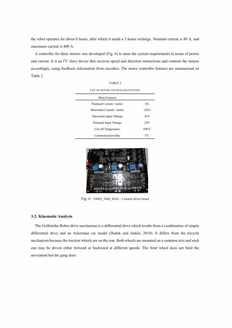
A controller for three motors was developed (Fig. 6) to meet the system requirements in terms of power
and current. It is an I2C slave device that receives speed and direction instructions and controls the motors
accordingly, using feedback information from encoders. The motor controller features are summarized on
Table 2.
TABLE 2
LIST OF MOTOR CONTROLLER FEATURES
Main Features
Nominal Current / motor 8A
Maximum Current / motor 120A
Maximum Input Voltage 36V
Nominal Input Voltage 24V
Cut-off Temperature 100°C
Communication Bus I2C
Fig. 6 - OMNI_3MD_MAX - 3 motors driver board
3.2. Kinematic Analysis
The Golfminho Robot drive mechanism is a differential drive which results from a combination of simple
differential drive and an Ackerman car model (Dudek and Jenkin, 2010). It differs from the tricycle
mechanism because the traction wheels are on the rear. Both wheels are mounted on a common axis and each
one may be driven either forward or backward at different speeds. The front wheel does not limit the
movement but the gang does.
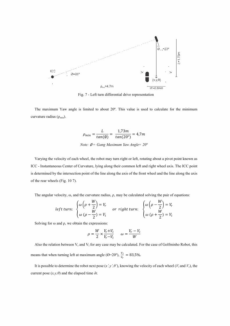
Fig.
The maximum Yaw angle is limited to about 20º.
curvature radius (ρmin).
�Note:
Varying the velocity of each wheel, the robot may turn right or left, rotating about a
ICC - Instantaneous Center of Curvature, lying along their common left and right wheel axis.
is determined by the intersection point of the line along the axis of the front wheel and the
of the rear wheels (Fig. 10 7).
The angular velocity, ω, and the curvature radius,
���� ���: �� � �
Solving for ω and ρ, we obtain the expressions:
Also the relation between Vr and V
means that when turning left at maximum angle (
It is possible to determine the robot
current pose (x,y,θ) and the elapsed time
Fig. 7 - Left turn differential drive representation
he maximum Yaw angle is limited to about 20º. This value is used to calculate
���� � ����∅� � 1,73����20°� � 4,7�
Note: ∅ = Gang Maximum Yaw Angle= 20°
Varying the velocity of each wheel, the robot may turn right or left, rotating about a pivot
Center of Curvature, lying along their common left and right wheel axis.
is determined by the intersection point of the line along the axis of the front wheel and the
the curvature radius, ρ, may be calculated solving the pair of equations
� !2 " � #$�� % !2 � � #&
' (� �)*+� ���: �� � % !2 " �� �� !2 � �
the expressions:
� � !2 , #$ #&#$%#& � � #$ % #&!
and Vl for any case may be calculated. For the case of Golfminho Ro
ing left at maximum angle (Ø=20º), -.-/ � 83,5%.
robot next pose (x’,y’,θ’), knowing the velocity of each wheel (
) and the elapsed time δt.
e for the minimum
pivot point known as
Center of Curvature, lying along their common left and right wheel axis. The ICC point
is determined by the intersection point of the line along the axis of the front wheel and the line along the axis
may be calculated solving the pair of equations:
" � #$� #&
'
For the case of Golfminho Robot, this
, knowing the velocity of each wheel (Vl and Vr), the
The following general equations apply for
Jenkin, 2010, Latombe, 1991).
3.3. Structural and Functional Validation
The main hardware platform was sub
(http://www.cyberbotics.com) simulation tool was used to accomplish two
truth model of the world and to validate the robot hardware operation
Fig. 8 – Platform structural design and functional validation using Webots
It is important to point out that all parts and joints were carefully designed respecting dimensions,
toughness, density and roughness of the real parts and materials.
Four main tests were performed using this tool: motion control, picking performance, ramp test and free
run on an irregular terrain (Fig. 8)
The most important conclusions driven from these tests showed that the robot i
slopes higher than 30º, the motion controller should take into account the hardware limitations such as the
gang maximum yaw angle so to preserve the integrity of the disks and the robot speed does not affect the
picking ability which was 100% effective in the simul
45567′9′:′; � 6cos �sin �
45567′9′:′; � 6 cos %sin
Left Turn:
At t + δt:
Right Turn:
At t + δt:
The following general equations apply for this type of differential robot (Choset, 2005
and Functional Validation
The main hardware platform was subject to testing on a simulation platform. The
) simulation tool was used to accomplish two objectives: to establish a ground
truth model of the world and to validate the robot hardware operation and behavior.
Platform structural design and functional validation using WebotsTM simulation tool
that all parts and joints were carefully designed respecting dimensions,
toughness, density and roughness of the real parts and materials.
Four main tests were performed using this tool: motion control, picking performance, ramp test and free
).
The most important conclusions driven from these tests showed that the robot is not expected to overcome
her than 30º, the motion controller should take into account the hardware limitations such as the
maximum yaw angle so to preserve the integrity of the disks and the robot speed does not affect the
picking ability which was 100% effective in the simulation tests.
455 � A7 % � B)�:�, 9 � C(B�:�D ��E�� %sin ��E�� 0�ωδt� C(B��E�� 00 0 1; , 67 % 45579 % 4559: ; 645574559�E� ;
455 � A7 � B)�:�, 9 % � C(B�:�D ��E�� sin ��E�� 0sin �ωδt� C(B��E�� 00 0 1; , 67 % 45579 % 4559: ; 6 45574559%�E�;
Choset, 2005, Dudek and
to testing on a simulation platform. The WebotsTM 6
objectives: to establish a ground
simulation tool
that all parts and joints were carefully designed respecting dimensions,
Four main tests were performed using this tool: motion control, picking performance, ramp test and free
s not expected to overcome
her than 30º, the motion controller should take into account the hardware limitations such as the
maximum yaw angle so to preserve the integrity of the disks and the robot speed does not affect the
;
;
3.4. Autonomous Navigation
Every planning strategy relies on knowing the exact location of the targets, in order to optimize the task,
reducing the pickup time, the energy required or any other functional cost.
A real important issue to solve is the fact that the golf balls location is unknown. So, the first problem to
deal with was the lack of detailed information about the targets position. A “Hybrid Localization System”
was proposed which relies on statistical information and it uses both real and virtual data to predict the actual
balls location on the field.
3.4.1. Hybrid Localization System
The hybrid localization system provides a virtual map containing previewed golf ball location, which is
continuously being updated, based on real information gathered by the robot. The system logs relevant data,
such as date, time and GPS data for each collected ball. The data is then processed to retrieve statistically
relevant information, such as the distribution probability, the frequency at which balls are sent to the field
and respective variations along the day, week, month and year. A virtual map is generated and continuously
updated.
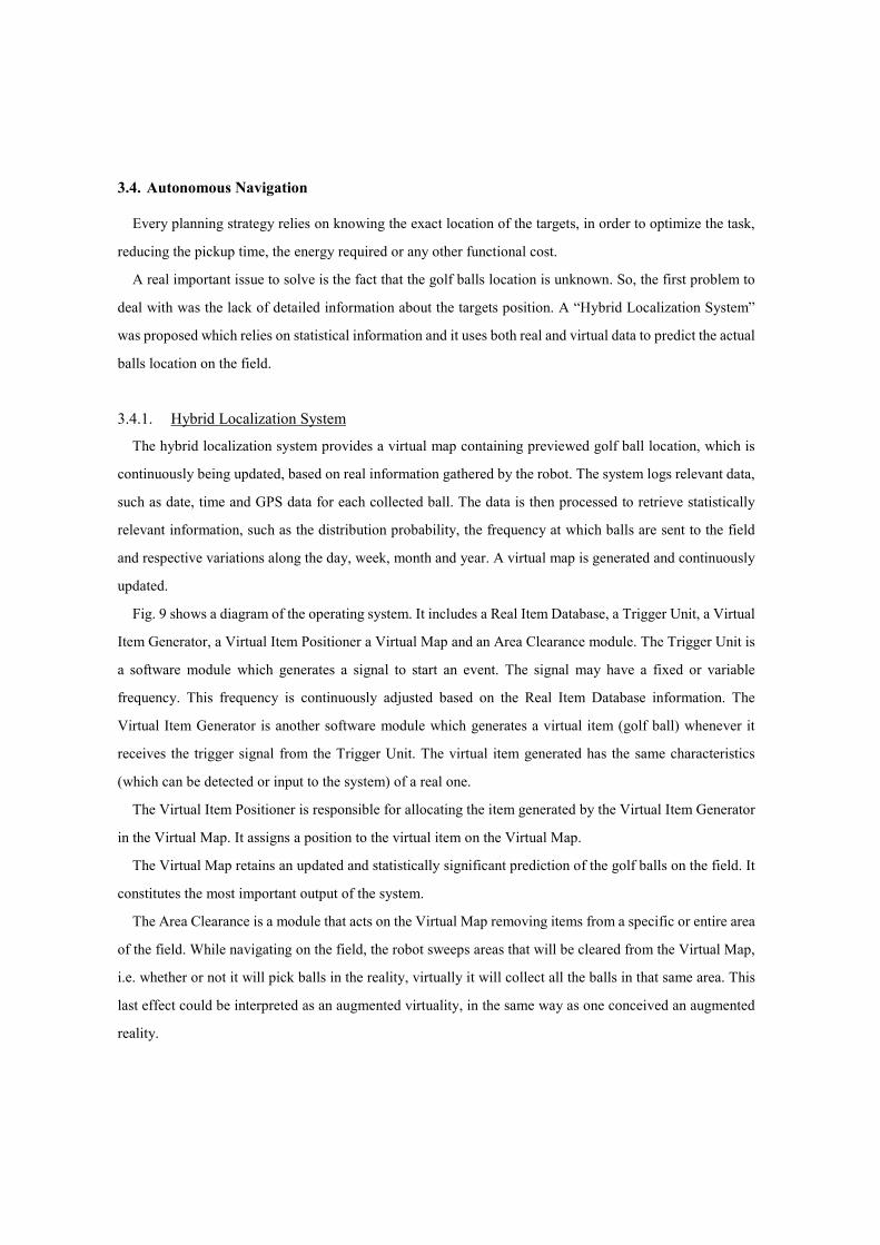
Fig. 9 shows a diagram of the operating system. It includes a Real Item Database, a Trigger Unit, a Virtual
Item Generator, a Virtual Item Positioner a Virtual Map and an Area Clearance module. The Trigger Unit is
a software module which generates a signal to start an event. The signal may have a fixed or variable
frequency. This frequency is continuously adjusted based on the Real Item Database information. The
Virtual Item Generator is another software module which generates a virtual item (golf ball) whenever it
receives the trigger signal from the Trigger Unit. The virtual item generated has the same characteristics
(which can be detected or input to the system) of a real one.
The Virtual Item Positioner is responsible for allocating the item generated by the Virtual Item Generator
in the Virtual Map. It assigns a position to the virtual item on the Virtual Map.
The Virtual Map retains an updated and statistically significant prediction of the golf balls on the field. It
constitutes the most important output of the system.
The Area Clearance is a module that acts on the Virtual Map removing items from a specific or entire area
of the field. While navigating on the field, the robot sweeps areas that will be cleared from the Virtual Map,
i.e. whether or not it will pick balls in the reality, virtually it will collect all the balls in that same area. This
last effect could be interpreted as an augmented virtuality, in the same way as one conceived an augmented
reality.
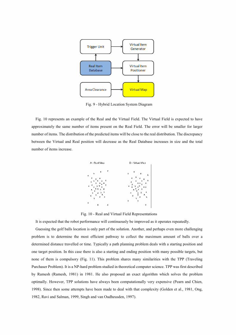
Fig. 10 represents an example of the Real and the Virtual Field. The Virtual Field is expected to have
approximately the same number of items present on the Real Field. The error will be smaller for larger
number of items. The distribution of the predicted items will be close to the real distribution. The discrepancy
between the Virtual and Real position will
number of items increase.
Fig.
It is expected that the robot performance will continuously be improved as it operates
Guessing the golf balls location is only part of the solution. Another, an
problem is to determine the most efficient pathway to collect the maximum amount of balls over a
determined distance travelled or time.
one target position. In this case there is also a
none of them is compulsory (Fig.
Purchaser Problem). It is a NP-hard problem studied in theoretical computer science.
by Ramesh (Ramesh, 1981) in 1981
optimally. However, TPP solution
1998). Since then some attempts have been made to deal with that complexity
1982, Ravi and Salman, 1999, Singh and van Oudheusden, 1997
Fig. 9 - Hybrid Location System Diagram
represents an example of the Real and the Virtual Field. The Virtual Field is expected to have
proximately the same number of items present on the Real Field. The error will be smaller for larger
number of items. The distribution of the predicted items will be close to the real distribution. The discrepancy
between the Virtual and Real position will decrease as the Real Database increases in size and the total
Fig. 10 - Real and Virtual Field Representations
he robot performance will continuously be improved as it operates
Guessing the golf balls location is only part of the solution. Another, and perhaps even more challenging
problem is to determine the most efficient pathway to collect the maximum amount of balls over a
or time. Typically a path planning problem deals with a starting position and
there is also a starting and ending position with many possible targets, but
Fig. 11). This problem shares many similarities with the
hard problem studied in theoretical computer science. TPP
in 1981. He also proposed an exact algorithm which solves the problem
TPP solutions have always been computationally very expensive
ome attempts have been made to deal with that complexity (Golden et al., 1981
Singh and van Oudheusden, 1997).
represents an example of the Real and the Virtual Field. The Virtual Field is expected to have
proximately the same number of items present on the Real Field. The error will be smaller for larger
number of items. The distribution of the predicted items will be close to the real distribution. The discrepancy
decrease as the Real Database increases in size and the total
he robot performance will continuously be improved as it operates repeatedly.
d perhaps even more challenging
problem is to determine the most efficient pathway to collect the maximum amount of balls over a
Typically a path planning problem deals with a starting position and
starting and ending position with many possible targets, but
shares many similarities with the TPP (Traveling
TPP was first described
ithm which solves the problem
have always been computationally very expensive (Pearn and Chien,
Golden et al., 1981, Ong,
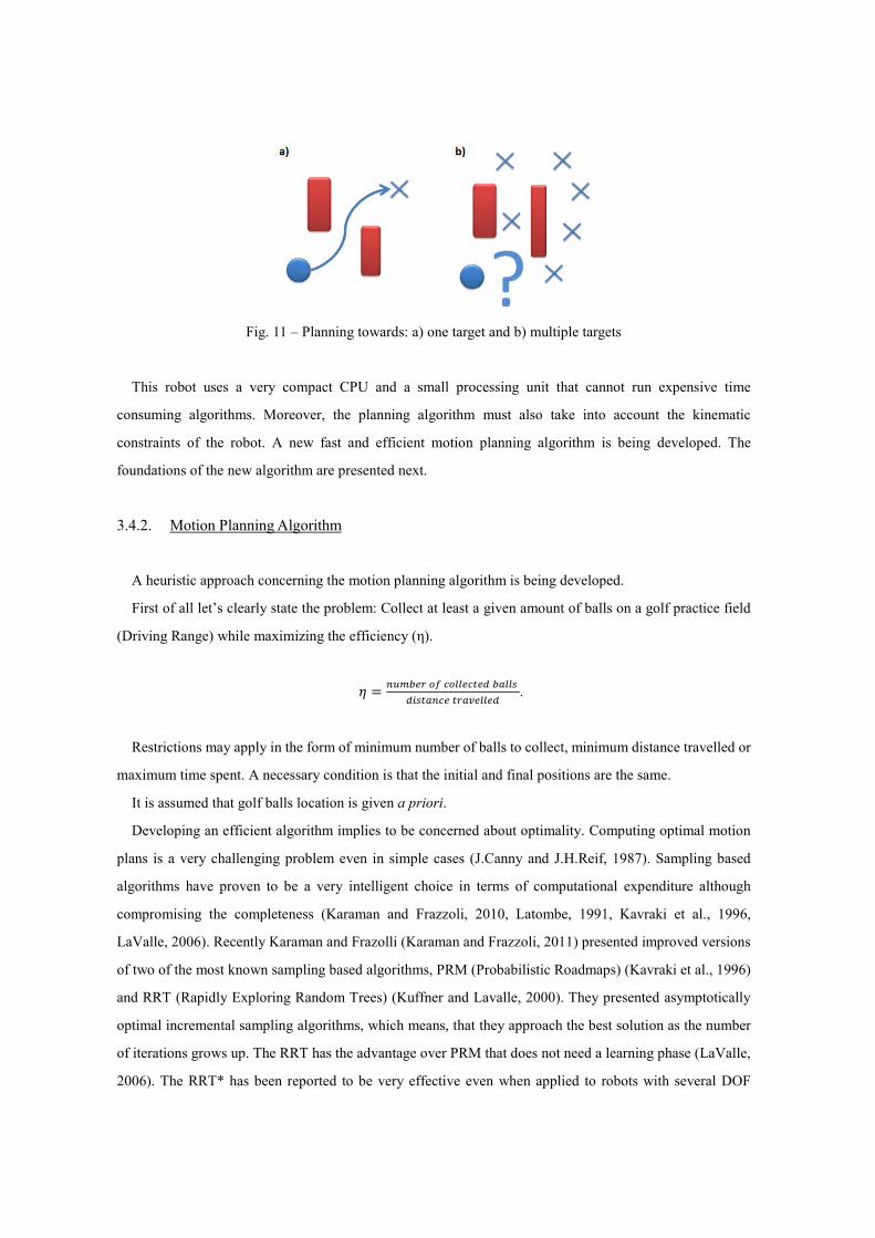
Fig. 11 – Planning towards: a) one target and b) multiple targets
This robot uses a very compact CPU and a small processing unit that cannot run expensive time
consuming algorithms. Moreover, the planning algorithm must also take into account the kinematic
constraints of the robot. A new fast and efficient motion planning algorithm is being developed. The
foundations of the new algorithm are presented next.
3.4.2. Motion Planning Algorithm
A heuristic approach concerning the motion planning algorithm is being developed.
First of all let’s clearly state the problem: Collect at least a given amount of balls on a golf practice field
(Driving Range) while maximizing the efficiency (η).
I � �J�KL$ MN OM&&LOPLQ KR&&S Q�SPR�OL P$RTL&&LQ .
Restrictions may apply in the form of minimum number of balls to collect, minimum distance travelled or
maximum time spent. A necessary condition is that the initial and final positions are the same.
It is assumed that golf balls location is given a priori.
Developing an efficient algorithm implies to be concerned about optimality. Computing optimal motion
plans is a very challenging problem even in simple cases (J.Canny and J.H.Reif, 1987). Sampling based
algorithms have proven to be a very intelligent choice in terms of computational expenditure although
compromising the completeness (Karaman and Frazzoli, 2010, Latombe, 1991, Kavraki et al., 1996,
LaValle, 2006). Recently Karaman and Frazolli (Karaman and Frazzoli, 2011) presented improved versions
of two of the most known sampling based algorithms, PRM (Probabilistic Roadmaps) (Kavraki et al., 1996)
and RRT (Rapidly Exploring Random Trees) (Kuffner and Lavalle, 2000). They presented asymptotically
optimal incremental sampling algorithms, which means, that they approach the best solution as the number
of iterations grows up. The RRT has the advantage over PRM that does not need a learning phase (LaValle,
2006). The RRT* has been reported to be very effective even when applied to robots with several DOF
(Degrees of Freedom) (Karaman et al., 2011, Perez et al., 2011).
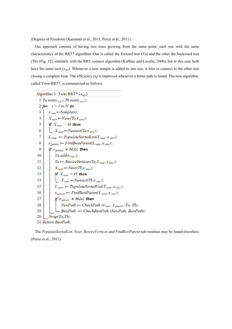
Our approach consists of having two trees growing from the same point, each one with the same
characteristics of the RRT* algorithm. One is called the forward tree (Ta) and the other the backward tree
(Tb) (Fig. 12), similarly with the RRT-connect algorithm (Kuffner and Lavalle, 2000), but in this case both
have the same root (xinit). Whenever a new sample is added to one tree, it tries to connect to the other tree
closing a complete loop. The efficiency (η) is improved whenever a better path is found. The new algorithm,
called Twin-RRT*, is summarized as follows:
The PopulateSortedList, Near, RewireVertices and FindBestParent sub-routines may be found elsewhere
(Perez et al., 2011).
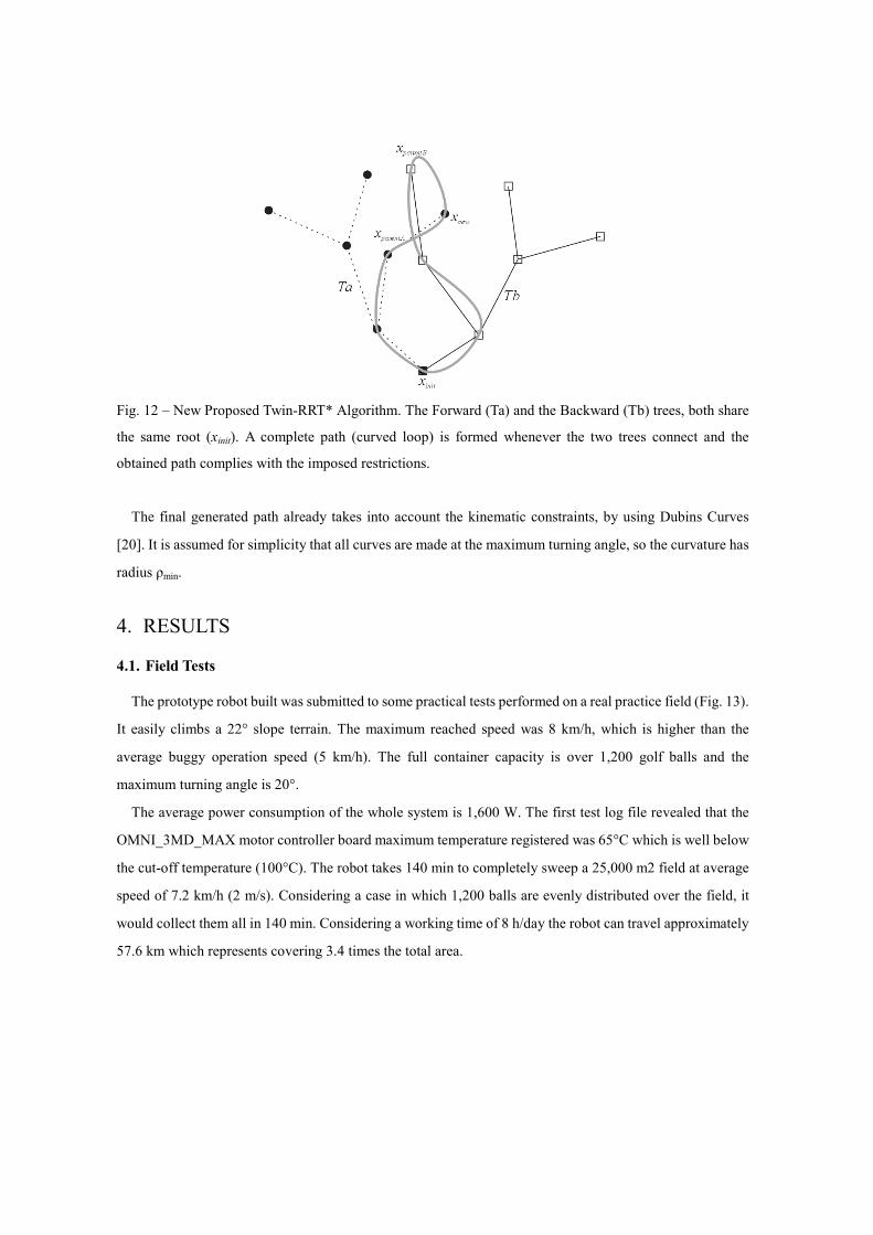
Fig. 12 – New Proposed Twin-RRT* Algorithm. The Forward (Ta) and the Backward (Tb) trees, both share
the same root (xinit). A complete path (curved loop) is formed whenever the two trees connect and the
obtained path complies with the imposed restrictions.
The final generated path already takes into account the kinematic constraints, by using Dubins Curves
[20]. It is assumed for simplicity that all curves are made at the maximum turning angle, so the curvature has
radius ρmin.
4. RESULTS
4.1. Field Tests
The prototype robot built was submitted to some practical tests performed on a real practice field (Fig. 13).
It easily climbs a 22° slope terrain. The maximum reached speed was 8 km/h, which is higher than the
average buggy operation speed (5 km/h). The full container capacity is over 1,200 golf balls and the
maximum turning angle is 20°.
The average power consumption of the whole system is 1,600 W. The first test log file revealed that the
OMNI_3MD_MAX motor controller board maximum temperature registered was 65°C which is well below
the cut-off temperature (100°C). The robot takes 140 min to completely sweep a 25,000 m2 field at average
speed of 7.2 km/h (2 m/s). Considering a case in which 1,200 balls are evenly distributed over the field, it
would collect them all in 140 min. Considering a working time of 8 h/day the robot can travel approximately
57.6 km which represents covering 3.4 times the total area.
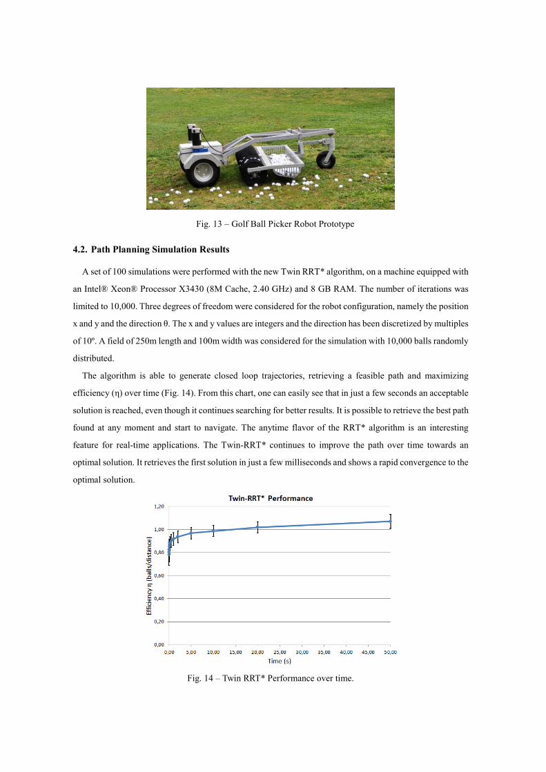
Fig. 13 – Golf Ball Picker Robot Prototype
4.2. Path Planning Simulation Results
A set of 100 simulations were performed with the new Twin RRT* algorithm, on a machine equipped with
an Intel® Xeon® Processor X3430 (8M Cache, 2.40 GHz) and 8 GB RAM. The number of iterations was
limited to 10,000. Three degrees of freedom were considered for the robot configuration, namely the position
x and y and the direction θ. The x and y values are integers and the direction has been discretized by multiples
of 10º. A field of 250m length and 100m width was considered for the simulation with 10,000 balls randomly
distributed.
The algorithm is able to generate closed loop trajectories, retrieving a feasible path and maximizing
efficiency (η) over time (Fig. 14). From this chart, one can easily see that in just a few seconds an acceptable
solution is reached, even though it continues searching for better results. It is possible to retrieve the best path
found at any moment and start to navigate. The anytime flavor of the RRT* algorithm is an interesting
feature for real-time applications. The Twin-RRT* continues to improve the path over time towards an
optimal solution. It retrieves the first solution in just a few milliseconds and shows a rapid convergence to the
optimal solution.
Fig. 14 – Twin RRT* Performance over time.
4.3. Patents
There are patents pending (“Fully autonomous or remotely operated golf ball picking system” -
Portuguese Patent 103 807, and United States under assessment, Patent on 30 September 2010:
US-2010-0250024-A1 and “SIMPLO - Hybrid Real-Virtual Electronic Information System” – Submitted on
December 2011) describing the technologies employed in this project, which makes this an attractive product
for industry. This project is being developed in consortium with SAR – Soluções de Automação e Robótica,
University of Minho and Partis Consulting.
5. CONCLUSIONS
This paper describes the industrial design and implementation of an autonomous robot to pick up golf
balls, following technical specifications. These were previously determined by a group of people, including
golf players, electrical and mechanical engineers and golf association directors, amongst others.
The overall system architecture and component integration was presented and field tests were conducted
to evaluate if technical specifications have been met. Preliminary results demonstrate that the prototype
meets the technical requirements concerning motors and batteries dimensioning, mechanical robustness,
capacity (1200 balls), speed (2m/s), maximum slope (22°) and maximum turning angle (45°).
This work is being developed jointly with industry, willing to manufacture and to export the final product.
A hybrid information system has been developed to statistically predict the golf balls location on the field.
A new path planning algorithm is being developed which shares similarities with both RRT-connect and
RRT*. This new Twin-RRT* algorithm produces closed loop trajectories and complies with the robot
kinematic constraints. It may be used to solve some TPP related problems while being computationally
feasible.
6. FURTHER WORK
The autonomous navigation feature will soon be implemented on the real robot. The path planning
strategy has shown preliminary promising results. Field tests are still required to prove the adequacy of the
planner to real environments. The Twin-RRT* algorithm will be improved to suit higher DOF (Degrees of
Freedom). Obstacle avoidance is also being introduced on the algorithm.
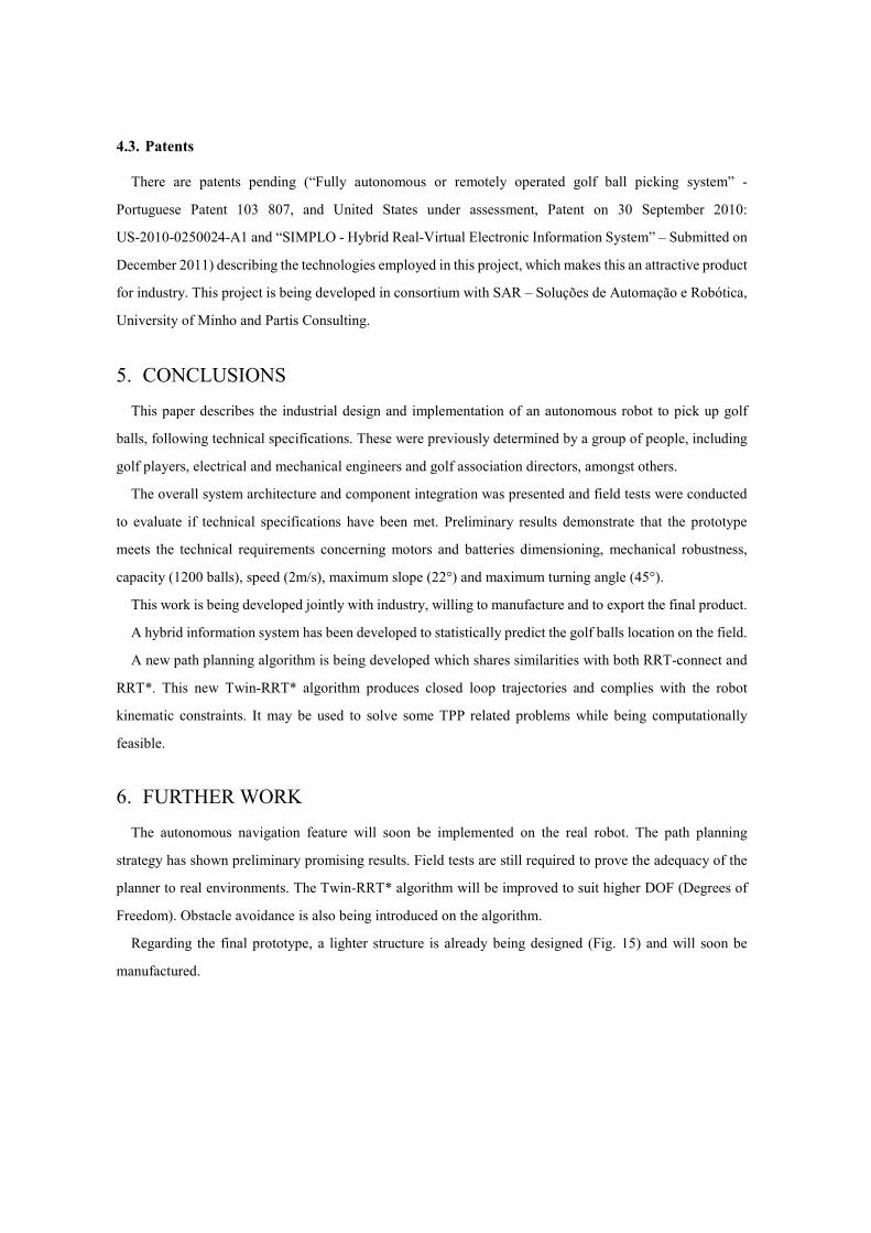
Regarding the final prototype, a lighter structure is already being designed (Fig. 15) and will soon be
manufactured.
Fig. 15 – Final golf ball picker robot design
7. ACKNOWLEDGEMENTS
The authors would like to thank the Portuguese Science Foundation - FCT “Fundação para a Ciência e
Tecnologia” for the PhD Grant No. SFRH / BD / 43008 / 2008, the Portuguese Golf Federation, and
Mecanarte, Metalúrgica da Lagoa Lda for all the support.
The project GOLFmINHO nº1583 is co-financed by European community fund FEDER (Fundo Europeu
de Desenvolvimento Regional), approved by QREN (Quadro de Referência Estratégico Nacional, Portugal
2007.2013) and supported by ON.2 (o Novo Norte – Programa Operacional da Região Norte), CCDRn
(Comissão de Coordenação e Desenvolvimento Regional do Norte) and ADI (Agência de Inovação).
REFERENCES: AUTOMATION, S. 2011. Golf Ball Picker Robot [Online]. Available:
http://www.softeeautomation.com/html/ballpicker.htm [Accessed 2011-05-24 2011].
CHOSET, H. 2005. Principles of Robot Motion: Theory, Algorithms, and Implementation, MIT Press © 2005
DE LOOZE, M. P., STASSEN, A. R. A., MARKSLAG, A. M. T., BORST, M. J., WOONING, M. M. & TOUSSAINT, H.
M. 1995. Mechanical loading on the low back in three methods of refuse collecting. Ergonomics, 38, 1993 -
2006
DUDEK, G. & JENKIN, M. 2010. Computational Principles of Mobile Robotics, Cambridge University Press.
GOLDEN, B. L., LEVY, L. & DAHL, R. 1981. Two generalizations of the traveling salesman problem. . OMEGA, 9,
439-445.
J.CANNY & J.H.REIF 1987. New lower bound techniques for robot motion planning problems. IEEE Symposium on
Foundations of Computer Science (FoCS). Los Angeles,CA.
JINWEI, G., RAVI, R., PETER, B. & SHREE, N. 2009. Removing image artifacts due to dirty camera lenses and thin
occluders. ACM Trans. Graph., 28, 1-10
KARAMAN, S. & FRAZZOLI, E. 2010. Incremental Sampling-based Algorithms for Optimal Motion Planning. CoRR,
abs/1005.0416.
KARAMAN, S. & FRAZZOLI, E. 2011. Sampling-based algorithms for optimal motion planning. Int. J. Rob. Res., 30,
846-894.
KARAMAN, S., WALTER, M. R., PEREZ, A., FRAZZOLI, E. & TELLER, S. Anytime Motion Planning using the
RRT*. Robotics and Automation (ICRA), 2011 IEEE International Conference on, 9-13 May 2011 2011.
1478-1483.
KAVRAKI, L. E., SVESTKA, P., LATOMBE, J. C. & OVERMARS, M. H. 1996. Probabilistic roadmaps for path
planning in high-dimensional configuration spaces. Robotics and Automation, IEEE Transactions on, 12,
566-580.
KUFFNER, J. & LAVALLE, S. RRT-connect: An efficient approach to single-query path planning. Proc. IEEE Int.
Conf. Robot. Autom. (ICRA, 2000. 995-1001.
LATOMBE, J. C. 1991. Robot Motion Planning, Boston, MA, Kluwer Academic Publishers.
LAVALLE, S. M. 2006. Planning algorithms, Cambridge University Press.
LI, Y. F. & CHEN, S. Y. 2003. Automatic recalibration of an active structured light vision system. Robotics and
Automation, IEEE Transactions on, 19, 259-268
LIMA, P., BONARINI, A., MACHADO, C., MARCHESE, F. M., MARQUES, C., RIBEIRO, F. & SORRENTI, D. G.
2001. Omni-Directional Catadioptric Vision for Soccer Robots. Special Issue of the Robotics and Autonomous
Systems Journal, Elsevier, Amsterdam, 36, 31.
MACHADO, C., CAMPOS, F., MARTINS, M., SAMPAIO, S. & RIBEIRO, F. 1999a. Footballer Autonomous Mobile
Robot – Control and Vision System. Festival International de Science et Technologie. Bourges, France.
MACHADO, C., CAMPOS, F., MARTINS, M., SAMPAIO, S. & RIBEIRO, F. 1999b. Mechanics and Electronics of the
Footballer Autonomous Mobile Robot. Festival International de Science et Technologie. Bourges, France.
MING-SHYAN WANG, C.-C. W. 2006. A Mobile Robot for Ball Picking. Proceedings of 2006 CACS Automatic Control
Conference, St. John's University, Tamsui, Taiwan.
ONG, H. L. 1982. Approximate algorithms for the traveling purchaser problem. Operations Research Letters, 1,
201-205.
PACHECO, L. F. C., OLIVEIRA, ANDRÉ J.B.DE, RIBEIRO, A.F. 2008. Mobile robot for autonomous golf balls
picking. Controlo 2008 : proceedings of the Portuguese Conference on Automatic Control. Vila Real, Portugal.
PACK, R. T., WILKES, D. M. & KAWAMURA, G. A software architecture for integrated service robot development.
Systems, Man, and Cybernetics, 1997. Computational Cybernetics and Simulation., 1997 IEEE International
Conference on, 12-15 Oct 1997 1997. 3774-3779 vol.4.
PEARN, W. L. & CHIEN, R. C. 1998. Improved solutions for the traveling purchaser problem. Computers &
Operations Research, 25, 879-885.
PEREZ, A., KARAMAN, S., WALTER, M., SHKOLNIK, A., FRAZZOLI, E. & TELLER, S. 2011.
Asymptotically-optimal Manipulation Planning using Incremental Sampling-based Algorithms. IEEE/RSJ
International Conference on Intelligent Robots and Systems (IROS).
RAMESH, T. 1981. Traveling purchaser problem. OPSEARCH, 18, 78-91.
RAVI, R. & SALMAN, F. 1999. Approximation Algorithms for the Traveling Purchaser Problem and Its Variants in
Network Design
Algorithms - ESA’ 99. In: NEŠETRIL, J. (ed.). Springer Berlin / Heidelberg.
RIBEIRO, F. 2007a. ENIGMA – Cadeira de Rodas Omnidireccional. Journal Robótica, 66, 50-51.
RIBEIRO, F., MOUTINHO, I., SILVA, P., FRAGA, C. & PEREIRA, N. 2004. Controlling Omni-directional Wheels of a
MSL RoboCup Autonomous Mobile Robot. Robotica’2004. Porto.
RIBEIRO, F., MOUTINHO, I., SILVA, P., BRAGA, P. AND PEREIRA, N. 2007b. Mobile Robot Construction for
Edutainment Application. Revista Robótica, 69, 12-16
SINGH, K. N. & VAN OUDHEUSDEN, D. L. 1997. A branch and bound algorithm for the traveling purchaser problem.
European Journal of Operational Research, 97, 571-579.
SUN-LI, W., MING-YANG, C. & WEN-CHUNG, H. 2005. Design and implementation of a prototype vision-guided
golf-ball collecting mobile robot. Mechatronics. 2005. ICM'05. IEEE International Conference on.
ULRICH, K. T. & EPPINGER, S. D. 2004. Product Design and Development, McGraw-Hill, New York.
WADA, K. 2009. Tutorial 1: Theoretical Aspects of Autonomous Mobile Robots. Parallel and Distributed Computing,
Applications and Technologies, 2009 International Conference on.
YANG, J., NAI GUANG, L. & DONG, M. Computer Vision Calibration New Easy Method. Information Technology
and Computer Science, 2009. ITCS 2009. International Conference on, 25-26 July 2009 2009. 102-105