Automotive Topology optimisation using Genesis. - GRM · Automotive Topology optimisation using...
18
Automotive Topology optimisation using Genesis. “Current methods and directions for the future” Dr Tayeb Zeguer – Jaguar Land Rover Ltd. Prepared by Bindu N Ali Location: 9 th July 2012
Transcript of Automotive Topology optimisation using Genesis. - GRM · Automotive Topology optimisation using...
Automotive Topology optimisation using Genesis.
“Current methods and directions for the future”
Dr Tayeb Zeguer – Jaguar Land Rover Ltd.
Prepared by Bindu N Ali
Location:
9th July 2012

Overview
Introduction to Advanced CAE Group
Topology Established Techniques
JLR current Topology approach to Nonlinear, crashworthiness and Pedestrian head impact
Future Vision for topology optimisation for both technology and integration
Conclusions

Introduction to Advanced CAE group Body CAE – ‘Support the CAE needs of the whole vehicle NVH,
Durability and Crash worthiness functional performance analysis’
SFE Modelling for
use in rapid
development studies
Programme Support
Early Concept Development
Methods Development
Multi Disciplinary Optimisation
Feasibility & cost

Topology Optimisation: Established Method Solid Topology
Many of the standard methods available within Genesis have been applied to everyday tasks in vehicle development,
examples of these include:
Solid Topology
Developing the rib pattern for a cast aluminium suspension turret considering NVH requirements

Established :Reinforcement Derivation Method
Primary Uses:
• Search for new load paths
• Identify weak joints
• Indicate poor areas with poor connection
RDM benefits:
• Identify new load paths, poor connectivity and poor joint condition
• Can be applied at any time in vehicle development program

Established :Reinforcement Derivation Method
Multi Load Cases
NVH Load Cases
Torsion
Bending
FFB Side MDB
ODB Side Pole
Rear MDB
Crash Load Cases

Established :Reinforcement Derivation Method
RDM Topology Results
Example Poor Joint Condition (Sled Runner section doesn’t feed
load into rear floor)
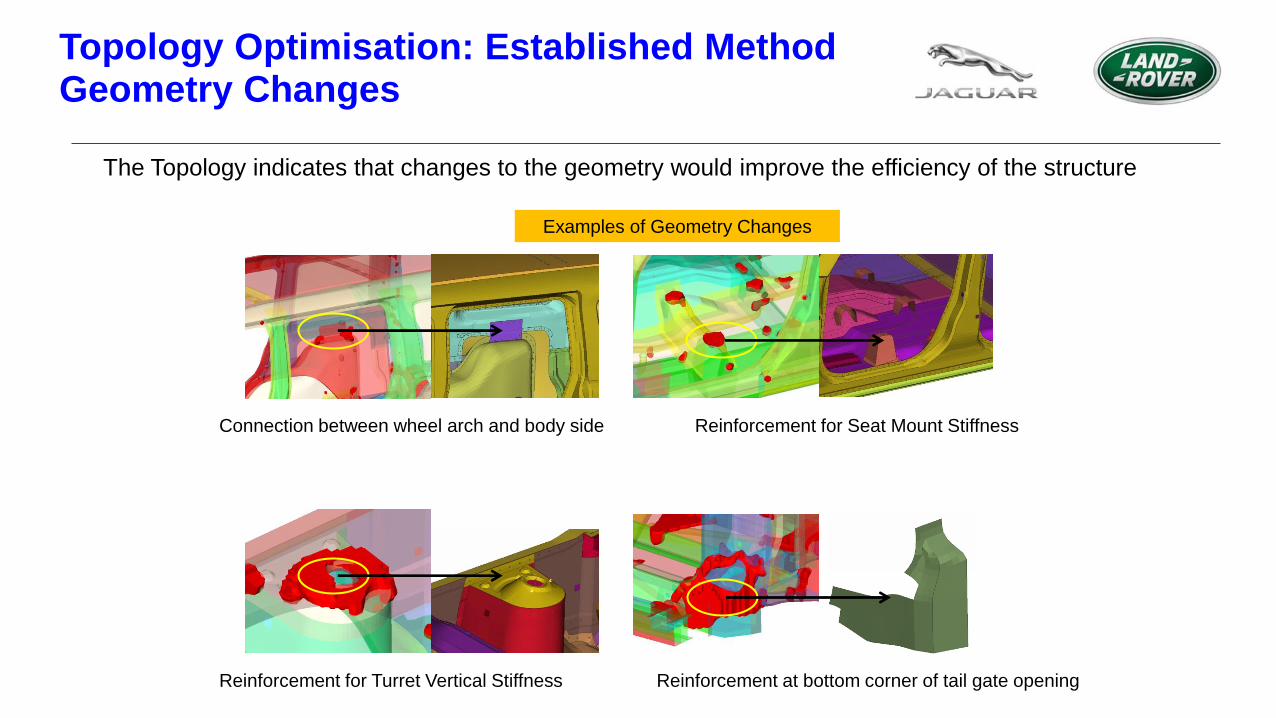
Topology Optimisation: Established Method Geometry Changes
The Topology indicates that changes to the geometry would improve the efficiency of the structure
Examples of Geometry Changes
Connection between wheel arch and body side Reinforcement for Seat Mount Stiffness
Reinforcement for Turret Vertical Stiffness Reinforcement at bottom corner of tail gate opening

Topology Optimisation: Established Method Topography Optimisation of Turret
A separate topography was carried out to achieve greater vertical stiffness
Topography
Initial shape Final shape

Topology Optimisation: Established Method Topometry and Sizing Optimisation
Sizing Topometry
JLR current Topology approach to Non-Linear Crash Optimisation
Objective:
• To develop a method to carry out concept optimisation of a vehicle structure in for multi
load cases (MDO)
Benefits:
• Ability to handle thousands of design variables, opening methods like Topology, Topometry
and Topography to crash
• Ability to consider NVH load cases at the same time
• Due to coupled nature of simulation contacts are considered
• No need to create approximate load cases
• Automated management tool, runs in the background until convergence
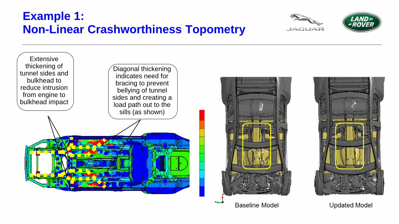
Extensive thickening of
tunnel sides and bulkhead to
reduce intrusion from engine to
bulkhead impact
Diagonal thickening indicates need for bracing to prevent bellying of tunnel
sides and creating a load path out to the
sills (as shown)
Example 1: Non-Linear Crashworthiness Topometry

• Longitudinals, crush cans and bumper beam
• Bumper beam reduced to minimum (as expected for FFB only optimisation
• Crush cans increased to absorb more energy in high speed
• Major BIW Components
• Tunnel and sill inners thickened
• Subframe thickness varied to create load path
• Bulkhead, floor, swan neck internals & subframe rear legs
• Outboard sections of swan neck reinforcements increased in thickness
• Floor to tunnel intersection region increased to maximum allowable
Example 1: Non-Linear Crashworthiness Topometry

Example 2: Non Linear Methods – Head Impact
Objective: To develop a method to carry out concept topology optimisation of bonnet
reinforcement considering both static strength and dynamic pedestrian requirements
• NVH Requirements
> Torsion
> Bending
> Rear Beam Stiffness
> Corner Stiffness
> Centre of Pressure Load
• Safety – Head Impact Requirements
> Adult and Child Head Impacts

Example 2: Non Linear Methods – Head Impact
Linear Topology Optimisation
LS-DYNA Model Update
LS-DYNA Head Impact Simulations
Use HIC Feedback to adjust Constraints
Automation Panel Automated Management Process
CSV File Containing Impact Points Define Head Model
LS-Dyna Base Model
Designable Parts
Target HIC
Launch Optimisation
Genesis Base Model

Example 2: Non Linear Methods – Head Impact
Topology Results Considering:
• Torsion
• Bending
• Rear Beam Stiffness
• Head Impacts
0
50
100
150
200
250
300
0.00
0.05
0.10
0.15
0.20
0.25
0.30
0.35
0 2 4 6 8 10
Co
nstr
ain
t V
iola
tio
n %
Ob
jecti
ve
Design Cycle
Optimisation History
Objective
ConstraintViolation
0
500
1000
1500
2000
2500
3000
3500
4000
0.0 2.0 4.0 6.0 8.0H
IC F
rom
Sim
ula
tio
n
Design Cycle
LS-DYNA HIC Vs Design Cycle
Topology Result for Each Design Cycle

Future Vision – Optimisation Technology
Features in the Tool:
• Development of Non-linear Topology such as for crash and general non linear loading
• Integrated Acoustic Optimisation
• Additional Manufacturing Constraints, i.e. shell casting
Uses of the Tool:
• Automated link from topology to shell mesh or geometry (CAD).
• Access to Optimisation for AVA/CAD engineers
• Implementation of new genesis features into existing processes e.g. contact optimisation

Conclusions
Linear topology is very well established and used regularly at
JLR including applications with composite materials
JLR has been pioneering the use of non linear topology with
currently available technologies and driving further development
Non linear topology, acoustics and process automation need be
developed and embedded into the current software.