
Sanjeev ghai income tax, Sanjeev ghai, Sanjeev ghai income tax

AUTOMOBILE
ENGINEERING
E-Notes
BY
SANJEEV YADAV
AND
MOHINDER SINGH
PAWAR

INTRODUCTION
1.1 AUTOMOBILE:- An automobile is a self-propelled vehicle which is used for the
transportation over the ground. Here, self-propelled vehicle which runs with its on power.
Components of automobile
1. Body
2. Chassis
Body is that part of an automobile who’s the passengers can sit in or where the cargo can be
placed. It also protects the passengers and cargo. The materials used for making of a body can be
wood steel aluminium and glass.
Chassis is the portion of vehicle without body is called chassis. It is also called frame of a
vehicle. The chassis is consist of following major units
A. Basic structure of frame
B. Power unit
C. Transmission system
D. Axels
E. Wheels and tires
F. Suspension system
G. Electrical system
H. Breaking system

2. Power system
2.1 Multi point fuel injection system
The function of multi point fuel injection system is to supply the proper ratio of petrol and air to
the cylinder. In this system the fuel is supplied by the fuel pump. At the time of starting , the
cold start injector is operated by the start injector timely switch. The cold start injector injects
fuel into the air intake chamber , thus enriching the air fuel mixture. The pressure regulator
checks the pressure of the fuel .there are two types of fuel injection in MPFI system :-
A. Port injection system
B. Throttle body injection system
2.1.1 Common rail direct fuel injection system:-
This system is now coming into use in recent diesel engine as is has the potential to reduce the
emission fuel consumption and to increase the power. Some of its important features are:-
1. It can give very high injection pressure in order of 1500 bar.
2. Shorting is much improved.
3. Full central at the end of injection.
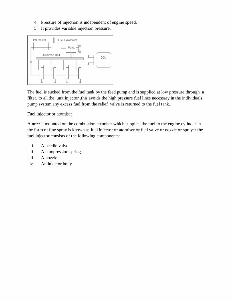
4. Pressure of injection is independent of engine speed.
5. It provides variable injection pressure.
The fuel is sucked from the fuel tank by the feed pump and is supplied at low pressure through a
filter, to all the unit injector .this avoids the high pressure fuel lines necessary in the individuals
pump system any excess fuel from the relief valve is returned to the fuel tank.
Fuel injector or atomiser
A nozzle mounted on the combustion chamber which supplies the fuel to the engine cylinder in
the form of fine spray is known as fuel injector or atomiser or fuel valve or nozzle or sprayer the
fuel injector consists of the following components:-
i. A needle valve
ii. A compression spring
iii. A nozzle
iv. An injector body

By atomizing the into very fine droplets, it increases the surface area of the fuel droplets
resulting in better mixing in air and subsequent combustion atomization by forcing the fuel
through a small orifice under high pressure.
Nozzle and types of nozzle
Nozzle is that part of an injector through the liquid fuel is sprayed into combustion chamber. The
types of injection nozzles are as follows
1. Single hole nozzle
2. Multi hole nozzle
3. Pintle nozzle
4. Pintaux nozzle
5. Circumferential orifice nozzle
Comparison between MPFI with carburetor system
MPFI Carburetor system
1. A fuel is atomized the mixing of fuel
and air is better giving homogenous
mixture for combustion.
2. Higher volumetric efficiency.
3. Combustion of fuel is lower
4. High fasten engine response
5. Compression ratio is high
Air and fuel mixture is less homogenous as
compare MPFI system
Less volumetric efficiency
More fuel consumption
As compression lower engine as response
Low compression ratio
6. More complicated system is required
7. Initial cost is high.
The system is simplified
Initial cost is low
2.2 Double overhead camshaft (DOMC) engine :-
In this engine, one camshaft operates the inlet valve and the other camshaft operates the exhaust
valves. DOMC are driven by a verity of methods. In case of V type of engines having DOMC
the intake camshaft are toward the inside of the engine and exhaust camshaft are towards the
outside. In DOMC the camshaft sprocket drives a timing chain which turns a center mounted
idler sprocket. The idler sprocket then drives a timing chain that rotates the camshaft
2.3 Twin cam 16 valve technology in 4-cylinder engine:-
Two valves and four valves per cylinder are used in mostly. To improve the engine breathing
capacity and to increase the power output many engines have valves per cylinder. The additional
valves allow more air fuel mixture to enter and leave. Hence, the volumetric efficiency of engine
is increased. Also valve had diameter is smaller and the valve wait less. This reduces the
efficiency of inertia and also helps in reducing the valve spring force needed to close a larger at
high engine speed.
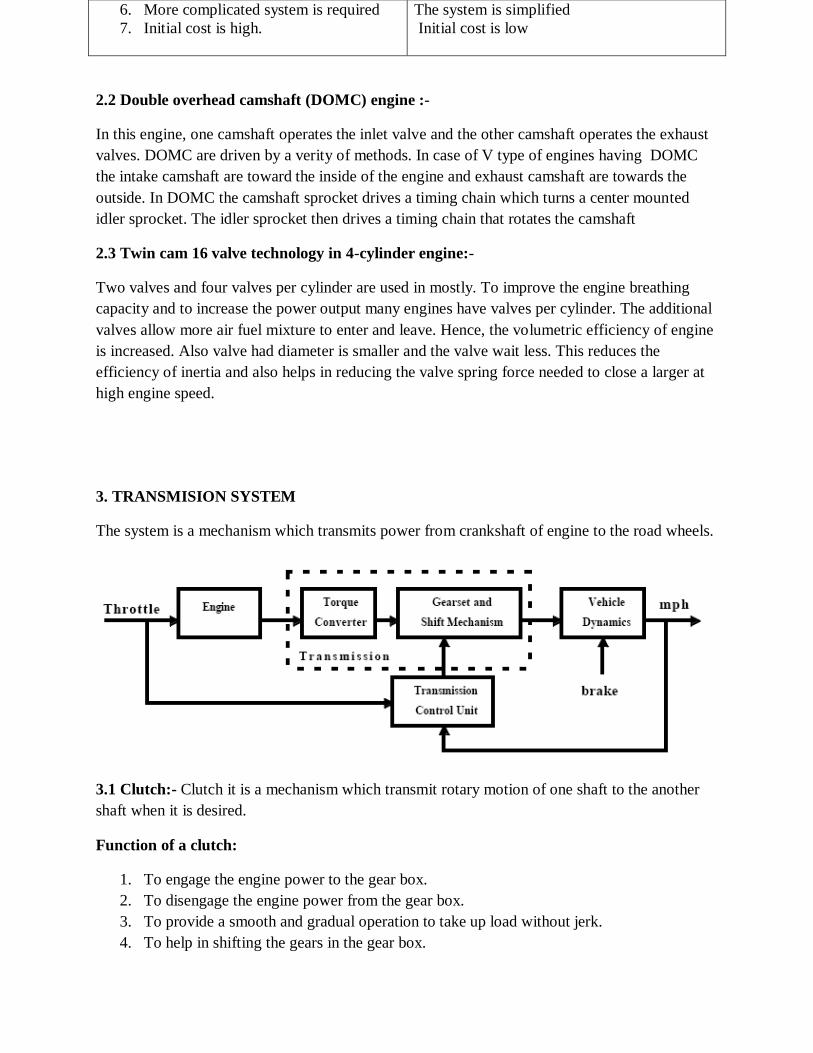
3. TRANSMISION SYSTEM
The system is a mechanism which transmits power from crankshaft of engine to the road wheels.
3.1 Clutch:- Clutch it is a mechanism which transmit rotary motion of one shaft to the another
shaft when it is desired.
Function of a clutch:
1. To engage the engine power to the gear box.
2. To disengage the engine power from the gear box.
3. To provide a smooth and gradual operation to take up load without jerk.
4. To help in shifting the gears in the gear box.
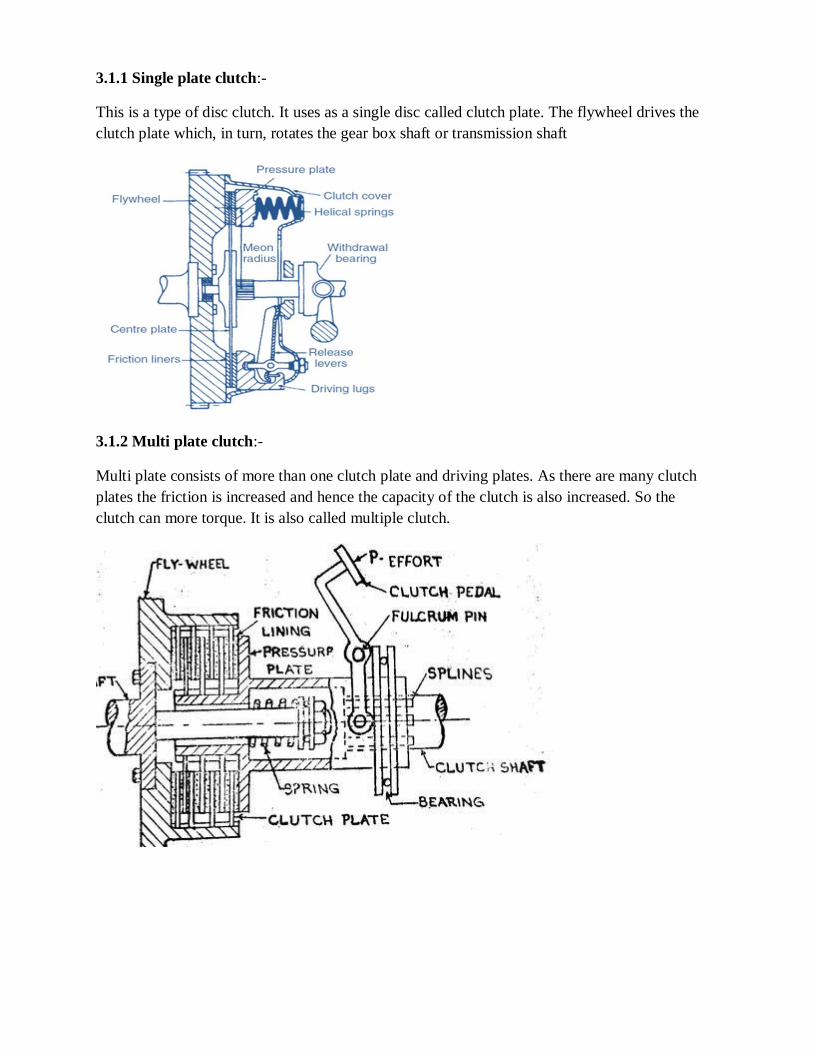
3.1.1 Single plate clutch:-
This is a type of disc clutch. It uses as a single disc called clutch plate. The flywheel drives the
clutch plate which, in turn, rotates the gear box shaft or transmission shaft
3.1.2 Multi plate clutch:-
Multi plate consists of more than one clutch plate and driving plates. As there are many clutch
plates the friction is increased and hence the capacity of the clutch is also increased. So the
clutch can more torque. It is also called multiple clutch.

3.1.3 Semi centrifugal clutch:-
Semi centrifugal clutch is useful for high torque transfer. More stiff springs are required for high
torque transfer in single plate clutch. As the stiffness is more, higher load on the clutch pedal is
required.
3.1.4 Centrifugal clutch:-
Centrifugal clutch is an automotive clutch.no clutch pedal is required to control the clutch
operation. It is controlled by the centrifugal forces. This engagement and dis engagement
operation depend upon the engine speed which is controlled by the accelerator .
3.1.5 Hydraulic clutch:-
Hydraulic clutch consist of a cylinder with piston, control valve, oil resources, pump and
accumulator. The piston is connected to the clutch with the help of linkage. The oil from
reservoir is send to accumulator tank with the help of pump which is operated by engine itself.
The accumulator tank is connected to the cylinder through control valve. The control valve is
electrically controlled by a switch in the gear lever.
3.2 Gear box
Gear box is a mechanism which provides us variation is speed and torque as required. The gear
box may be manually or automatic
Function of gear box and transmission:-
1. A lot of variation in torque is required at road wheels of a vehicle. A gear box service
this purpose. It provides high torque at starting and high speed while running.
2. Gear box also provide means to reverse the direction of the vehicle.

3. It provide a neutral position, the position at which the power flow to road wheels is
disconnected.
Types of Gear boxes are as following:-
1. Sliding mash Gear box
2. Constant mash Gear box
3. Synchromesh Gear box
3.3 Torque convertor
Torque convertor gives more torque at its output shaft. This torque multiplication can be up to 3
times. These it service the purpose of gear box which provide higher torque at standing. So it is
used in place of gear box
Construction of Torque convertor:-
A Torque convertor consist of mainly three components
1. Driving member or impeller
2. Driven member or turbine
3. Fixed member or stator
3.4 Overdrive:-
The purpose of overdrive is to rotate the propeller shaft faster than the speed of the engine
crankshaft. Generally it is used at high gear position. It service the purpose of increasing vehicle
speed. Mostly the gear ratio of high gear to crankshaft speed is 1:1 i.e. at high gear speed of
propeller shaft is equal to the speed of crank shaft. The overdrive serve the purpose of increasing
the speed of propeller shaft future.
3.5 Propeller shaft:-
This shaft is used to transmit the power from transmission to rear axle or differential in case of
rear will drive vehicle. This shaft does not remain at fixed position.
3.6 Universal joint:-
This joint is used to connecting two shafts whose axis are inclined to each other.
Function of universal joint
1. It transmit power to shaft where axis are inclined to each other
2. It accommodates the change in angle between the axis of two shaft.
3.7 Real axle:-
It transmits from differential to the real wheels. It takes load of vehicle and its occupants. It
withstands various thrust expand by the road wheels and springs. It also experience various force
and torque
Types of real axle:-
1. Semi floating axle
2. Full floating axle
3. Three quarter axle
3.8 Front axle:-
1. It takes the front load of the vehicle.
2. It accommodated the king pin which carries step axle for standing the vehicle.
3. It takes the torque load wheels applying the breaks.
3.9 Wheels:-
A vehicle cannot run without wheels are fitted on wheels hub.On the wheels are fitted tyres
which remain in contact with the road surface.
Types of wheels
1. Pressed steel disc wheel
2. Wire wheels
3. Light alloy cast wheels
3.10 Tyre:-
Tyre is that part of a vehicle which have contact with the road surface. It is mounted on the
wheels and fits over the rim of the wheel.
Classification of Tyres:-
1. According to section
i. Solid tyre
ii. Pneumatic tyre
(a) Tyres with tube
(b) Tubeless tyres
2. According to car case design
i. Cross ply tyres
ii. Radial tyres
iii. Belted bias tyres
3. According to material
i. Natural rubber tyres
ii. Synthetic tyres
4. Wheel balancing:-
It may be defined as the wheel and tyre assembly may be out of balancing with respect to its axis
of rotation. It may be due to uneven weight distribution on the assembly. To rectify this, what
balancing is done.
Types of wheels balance
i. Static balancing (wheels at rest)
ii. Dynamic balancing(wheels in balancing)

5. Steering system:-
Steering system is the mechanism which performs the task of giving directional change to a
vehicle.
Requirement of a good steering system:-
i. It should be easy to operate
ii. It should be very accurate
iii. It should have self-countering ability
iv. It should not transmit road shock to steering wheels
Components of steering system:-
i. Steering wheels
ii. Steering column
iii. Steering box
iv. Pitman arm
v. Pull and push rod
vi. Steering knuckle arm
vii. Tie rod
viii. Tie and arm
ix. King pin
Types of gears:-
1. Worm and wheel steering gear
2. Worm and roller steering gear
3. Worm and nut steering gear
4. Rack and pinion steering gear
5.1 Power steering:-
For steering of medium and heavy vehicles, larger amount of torque is required. Hence driver
has to put more effort. To reduce this effort, power steering systems are used which provides
automatic hydraulic assistance for turning the vehicle. These system are lubrications of viscosity
rating 5AE 5W or SAE low. The operating pressure is of order of 7MPa.

Principle of power steering:-
Fluids under pressure enter the appropriate sides of a cylinder where the steering wheel is rotated
and valve is opened. This fluid applies pressure on one side of a piston to move it. This
movement of piston operates the steering linkage to steers the wheels in a desired direction.
Types of power steering:-
1. Integral power steering system
2. linkage type or semi-integral power steering system
5.1.1 Integral power steering system:-
In this system the power steering unit is an integral part of steering gear. The main components
of an integral power steering system are:-
1. Hydraulic pump assembly.
2. Steering gear assembly.
3. Pressure nose assembly.
4. Return line assembly.
5.1.2 Linkage type or semi-integral steering system:-
In this type of system the power system is attached between the frame of the vehicle and steering
system.
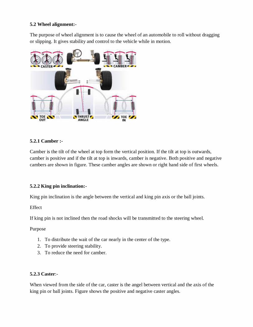
5.2 Wheel alignment:-
The purpose of wheel alignment is to cause the wheel of an automobile to roll without dragging
or slipping. It gives stability and control to the vehicle while in motion.
5.2.1 Camber :-
Camber is the tilt of the wheel at top form the vertical position. If the tilt at top is outwards,
camber is positive and if the tilt at top is inwards, camber is negative. Both positive and negative
cambers are shown in figure. These camber angles are shown or right hand side of first wheels.
5.2.2 King pin inclination:-
King pin inclination is the angle between the vertical and king pin axis or the ball joints.
Effect
If king pin is not inclined then the road shocks will be transmitted to the steering wheel.
Purpose
1. To distribute the wait of the car nearly in the center of the type.
2. To provide steering stability.
3. To reduce the need for camber.
5.2.3 Caster:-
When viewed from the side of the car, caster is the angel between vertical and the axis of the
king pin or ball joints. Figure shows the positive and negative caster angles.
The caster is positive when the king pin axis meets the ground at a point in front of the wheel
center and it is negative the ground behind the wheel center.
Effect :-
In the rear wheel drive vehicle the rear wheels gives a posing effect to the front wheels.
Purpose:-
1. To provide directional control to a vehicle by enabling the front wheels to maintain a
straight ahead position.
2. To offset road crown.
5.2.4 Toe-in and toe-out :-
Toe-in and toe-out are shown in figure (A) and (B) respectively. The toe-in is the amount by
which the front wheels is set closer than the rear of the front wheels. In figure (A), toe-in is
equal to the B-A. Toe-out is the amount by which the rear of front of wheel is set closer than the
front of front wheel. In the figure B toe-out is equal to A-B.
Effects
For ideal running toe should be zero. This means the wheels should be parallel to each other
while rolling straight ahead. But in the rear drive vehicle when the vehicle is running forward,
read resistance cause the front types tyres to spread apart in front side.
6. Braking system:-
Breaks are expect to stop a moving vehicle in shortest time and distance.
Requirements of good braking system :-
1. The fast running vehicle should be stop in shortest distance and time.
2. The brakes should be equally effect on good and bad roods.
3. Brakes should work equally good in all weather.
4. Pedal effort applied by the driver for braking should be less.
Types of breaks :-
Breaks can be classified according to the following consideration:-
Purpose:-
i. Foots breaks for service breaks.
ii. Hand breaks or braking brakes.
Location :-
i. Wheel brakes (located at wheels).
ii. Transmission breaks (located at transmission).
Construction:-
i. Drum brakes.
(a) Internal expanded brakes.
(b) External contracting brakes
ii. Disc brakes.
Mode of operation :-
i. Mechanical brakes.
ii. Hydraulic brakes.
iii. Vacuum brakes.
iv. Air brakes.
v. Electric brakes.
6.1 Mechanical breaks:-
The brakes which are operated mechanically by means of levers, linkages, pedals, cams and bells
cranks etc. Mechanical breaks were employed in olden days but non hydraulic and other types of
braking system have and articulated trailers employ such types of breaks. Such types of brakes
are also employed in parking brakes. Figure shows the layout of mechanical brake system.
Components:-
i. Brake pedal
ii. Links and livers
iii. Break drum
iv. CAM
v. Break shoe
vi. Retracting spring
Uses:-
Mechanical brakes are used in some large trucks and articulated trailers, parting brakes of the
vehicle are mechanical type brakes.
6.2 Hydraulic brakes:-
Brakes which are operated by means of hydraulic pressure of fluid pressure are known as
hydraulic brakes.
Components:-
i. Brake pedal
ii. Master cylinder
iii. Fluid reservoir
iv. Wheel cylinder
Principle:-
Master cylinder is the main component of hydraulic brake system which contain reservoir for
brake fluid. Fluid pressure is involved in this type of brakes. So, hydraulic brakes act according
to the principle of ‘pascals law’ which states that pressure applied to a liquid in a closed vessel is
equally transmitted in all directions.
6.3 Vacuum brake:-
In vacuum brakes, the suction from the engine inlet manifold is utilized for brake application.A
piston or diaphragm is operated in a cylinder and provided with suitable linkage for brake
application.

Components:-
i. Exhauster
ii. Vacuum reservoir
iii. Vacuum booster
Types of vacuum brakes:-
1. Suspended air type
2. Suspended vacuum type
6.4 Air braking system:-
Main parts of air braking system are:-
i. Air filter
ii. Compressor
iii. Unloader valve
iv. Air reservoir
v. A brake valve
vi. Pressure gauge
vii. Safety valve
viii. Brake chambers
ix. Low pressure indicator
x. Stop light switch
Layout:-
The air is sucked through the air filter by the compressor and is sent to the reservoir. When the
pressure inside the reservoir reaches a predetermined valve prevents any further rise of pressure.
When the pressure drops to be predetermined value the unloader valve opens and pressure in
again build up.

6.5 Brake shoe adjusting:-
After considerable use of brake lining and drum get worm off, as the wheel cylinder piston had a
fixed stroke. When the brake shoe and drum get worn off, the brake shoe cannot exert sufficient
pressure and the brakes start slipping . This gap between brake shoe lining and drum is called
the clearance . To adjust the clearance b/w brake drum and shoe , brake adjusters are used .
6.6 Antilock brake system:-
Antilock braking system is an automobile safety system which allows the wheels of a motor
vehicle to maintain tractive contact with the road surface according to driver inputs while
braking . It prevents the wheel from locking up and avoid uncontrolled skidding . It generally
offers improved vehicle control and decreases stopping distances can dry and slippery surfaces .
An antilock braking system consist of following components
i. Electronic control unit
ii. Speed sensors
iii. Solenoid valves on each brake circuit
iv. Master cylinder
v. Wheel brake cylinder

7. Suspension System:-
7.1 Introduction:-
The suspension system provides cushioning effect to the vehicle against the road roughness by
giving minimum up and down movement to body and chassis.
Functions of suspension system:-
1. It supports the weight of the vehicle called sprung weight.
2. It always maintains the grip between tyre and road.
3. It allows the vehicle to take turn with minimum rolling.
4. It holds the wheels in alignment.
5. It provides comfort to occupants.
7.2 Sprung and Unsprung weight:-
Sprung weight- It is weight of suspension system and the weight of vehicle which is
supported on suspension system.
Unsprung weight- It is weight which is not supported by the suspension system.
7.3 Brake dip and wind dip:-
Brake dip when brakes are applied to a moving vehicle, the nose of vehicle tends to lower
down, thus compressing the front suspension springs thus phenomenon is called as brake dip.
Wind dip when vehicle starts moving a driving torque is applied which tends to lift the front
of the vehicle. Thus, the suspension springs are deflected. This phenomenon is called wind
up.
7.4 Suspension spring:-
The various type of springs used in suspension system are called suspension spring.
7.4.1 Spring rate:-
It is the softness or hardness of the spring. The load required to compress spring through one
unit of distance is called spring rate.
7.4.2 Type of suspension springs:-
1. Leaf spring
2. Coil spring
3. Torsion bar
4. Air spring

Leaf spring:-
Leaf spring consists of long and flat flexible plates made of spring steel. Each plate is
called leaf. Following parts of leaf spring
(a) Semi elliptic leaf spring
(b) Full elliptic leaf spring
(c) Quarter elliptic leaf spring
(d) Transverse leaf spring
Coil spring:-
The coil spring is made of a length of spring steel rod, which is round in cross section, by
winding it in the shape of a coil. Its ends are made flat so that it can seat properly.

Advantages:-
(a) It does not produce noise
(b) It does not have static friction
(c) It takes both bending and shear stresses
7.5 Torsion bar:-
Torsion bar is a spring steel rod which is twist taking shear stresses. It is generally used in
independent suspension system. One end of the torsion bar is fixed with the frame so that
its end cannot rotate.
Advantages
(a) It is light in weight
(b) It occupy less space than leaf spring
7.6 Air spring:-
The air spring consists of rubber bag filled with compressed air. There is a valve on the
bagwhich is connected to an air compressor. The compressor keeps the air bag inflated.
The bag is placed between frame and axle.
Advantages
(a) It maintains a constant distance between frame and road surfaces
(b) This is low frequency spring which gives a comfortable ride
(c) Its frequency remains constant.

7.6.1 Material for springs:-
1. Chrome vanadium steel
2. Silico manganese steel
3. Carbon steel
8. Auto electrical system
8.1 Introduction:-
Battery is an electro chemical device which converts chemical energy into electrical
energy. It does not store electricity but it stores electrical energy in form of chemical
energy.
8.2 Functions of battery in automobile:-
1. It supplies electric current for the starting motor and ignition system when the engine
is started.
2. It supplies electric current for the lights, stereo, heater and other accessories whenever
required.
3. It acts as voltage stabilizer for all the devices.
8.3 Types of batteries:-
1. Lead acid battery
2. Alkaline battery
3. Zinc air battery
4. Silver zinc battery
5. Nickel cadmium battery
8.3.1 Battery cell:-
It is a case which consists of plates, separators and electrolyte. Each battery consists of
two or more cells. Types of battery cells:
1. Primary cells
2. Secondary cells
8.3.2 Lead acid Battery:-
1. Sponge lead in solid form
2. Lead peroxide in paste form

3. Sulphuric acid in liquid form
Construction of lead acid battery:-
1. Battery case
2. Plates
3. Separators
4. Electrolyte
5. Cell covers and vent plugs
8.3.2 Specific gravity of Electrolyte:-
The specific gravity of electrolyte is a measure of Sulphuric acid content in the
electrolyte.
Effects of temperature on specific gravity:-
The specific gravity of electrolyte decrease with the increase of its temperature and vice-
versa. The specific gravity of Sulphuric acid solution is 1.265 at 27°C.
Battery testing:-
1. Specific gravity test.
2. Terminal voltage test.
3. High rate discharge test.
4. Cadmium probe test.
Battery maintenance:-
1.Vent holes should not get choked. After choking, the gases cannot come out and battery
can burst.
2. Avoid overcharging and undercharging.
3. Do not keep the battery idle for long periods.
4. Never keep the battery in fully discharged state otherwise the plates can be sulphated
and the battery life can work no more.
5. Never bring naked flame near the battery because hazards gases escape from the
battery.

9. Ignition system:-
In the spark ignition engine, the compression ratio is lower and the self-ignition
temperature of petrol is higher, therefore, to initiate combustion, an ignition system is
must for igniting the mixture. This spark is produced between two electrodes of a spark
plug by high voltage electric current.
i. Coil or battery ignition System
ii. Magneto ignition System
Requirement of good ignition system:-
i. It should be light, effective and reliable in service.
ii. It should be compact and easy to maintain.
iii. There should be no missing cycle due to failure of spark.
iv. It should be cheap and convenient to handle.
v. It should function efficiently over the entire range of engine speed.
9.1.1 Battery ignition system:-
Components of battery ignition system:
1. A battery of 6 to 12 volts.
2. Ignition switch.
3. Ignition coil with a ballast resistor.
4. Distributor.
5. Contact breaker.
6. Condenser.
7. Spark plug.

Advantages:-
1. It provides quality spark at low speeds.
2. It is cheap.
3. It can be used easily in buses and cars.
4. Maintenance cost is very less except cost of battery.
Limitations:-
1. The primary voltage decreases as the engine speed increases.
2. Maintenance cost of battery is high.
3. The engine cannot be started if the battery is discharged.
9.1.2 Magneto ignition system:-
The principle of magneto ignition system is similar to the battery ignition system except that the
magnetic field in the core of primary and secondary winding is produced by a rotating magnet.
As the rotating magnet rotates, the magnetic field is produced in the coils. Magnetic flux varies
from a positive maximum to negative maximum and vice versa.

Advantages :-
1. It is best for high speed vehicles.
2. It is less expensive.
3. This system is favored for two wheelers due to light weight and low maintenance.
Disadvantages:-
1. Since the wiring caries a very high voltage, therefore, thus there is a strong possibility of
causing engine misfire due to leakage.
2. To avoid above problem, the high tension wire need suitable shielding.
3. At low speed, it develops poor quality of spark at the time of starting.
9.2 Dynamo:-
It is a D.C. generator which converts mechanical energy from engine shaft into direct current. A
conductor wire loop is rotated in a magnetic field to induce electric current into D.C. with the
help of a commutator.

9.3 Alternator:-
It is an A.C. generator. The current output is in the form of alternating current. But all the
electrical systems in the automobilesand the battery required D.C. form, so silicon diodes are
used to change the alternating current to direct current.

9.4 Cut out relay:-
When the generator speed is very low, due to which the output is not sufficient to balance the
battery voltage, the necessity to cut out the generator from the battery arises otherwise the battery
would discharge into the generator.
9.5 Regulator :-
The output from D.C. generator goes on increasing the increase the speed of armature. As the
amount of current is more, the speed is also increased and again due to high speed the current is
increased. This current is also fed to armature winding which again increases the speed.