AUTOMOBILE AERODYNAMICS INFLUENCED BY AIRFOIL …repozitorij.fsb.hr/5552/1/Automobile...
9
International Journal of Automotive Technology, Vol. 17, No. 3, pp. 377-385 (2016) DOI 10.1007/s12239-016-0039-4 Copyright © 2016 KSAE/ 090-03 pISSN 1229-9138/ eISSN 1976-3832 377 AUTOMOBILE AERODYNAMICS INFLUENCED BY AIRFOIL-SHAPED REAR WING A. BULJAC, I. DŽIJAN, I. KORADE, S. KRIZMANIĆ and H. KOZMAR * Faculty of Mechanical Engineering and Naval Architecture, University of Zagreb, Ivana Lučića 5, 10000 Zagreb, Croatia (Received 3 March 2015; Revised 4 September 2015; Accepted 29 November 2015) ABSTRACT-Computational model is developed to analyze aerodynamic loads and flow characteristics for an automobile, when the rear wing is placed above the trunk of the vehicle. The focus is on effects of the rear wing height that is investigated in four different positions. The relative wind incidence angle of the rear wing is equal in all configurations. Hence, the discrepancies in the results are only due to an influence of the rear wing position. Computations are performed by using the Reynolds-averaged Navier-Stokes equations along with the standard k-ε turbulence model and standard wall functions assuming the steady viscous fluid flow. While the lift force is positive (upforce) for the automobile without the rear wing, negative lift force (downforce) is obtained for all configurations with the rear wing in place. At the same time, the rear wing increases the automobile drag that is not favorable with respect to the automobile fuel consumption. However, this drawback is not that significant, as the rear wing considerably benefits the automobile traction and stability. An optimal automobile downforce-to-drag ratio is obtained for the rear wing placed at 39 % of the height between the upper surface of the automobile trunk and the automobile roof. Two characteristic large vortices develop in the automobile wake in configuration without the rear wing. They vanish with the rear wing placed close to the trunk, while they gradually restore with an increase in the wing mounting height. KEY WORDS : Automobile aerodynamics, Rear wing, Aerodynamic forces, Steady Reynolds-averaged Navier-Stokes equations, k-ε turbulence model 1. INTRODUCTION Various technical solutions have been explored to optimize fuel consumption of road vehicles as well as to improve their traction and stability. An increase in the maximum tire lateral force, which is improving car traction and cornering ability, can be achieved by increasing the tire normal force (Katz, 1996). This can be obtained by redesigning the automobile shape using various aerodynamic devices. These devices generally neutralize the uplift force and produce the downforce, thus increasing the tire normal force and improving the vehicle dynamics without increasing the actual mass of the car. One of the important aerodynamic parts commonly used to improve automobile aerodynamics is an airfoil-shaped rear wing placed at the trunk of the vehicle. While the basic aerodynamic characteristics of the rear wing are generally known, further work is still required with respect to the wind incidence angle and the wing mounting height at the trunk of the automobile. The general goal is to increase the automobile downforce to improve its traction and stability, while simultaneously try to avoid considerable drag increment, which adversely increases fuel consumption. While the automobile aerodynamics has been traditionally studied experimentally in the wind tunnels, the Computational Fluid Dynamics (CFD) has been increasingly used to investigate this topic, even though further improvements are still necessary to make this approach more reliable (Guilmineau, 2008). Chien-Hsiung et al. (2009) studied influence of a rear wing on aerodynamic behavior of a passenger car. Their CFD results indicate an improved vertical stability of the vehicle in configurations with a rear wing. The two dominant rear vortices (C-pillar vortices) in the wake of the automobile, developing from the vertical supports of an automobile window area and adversely influencing an overall vehicle aerodynamics, reduce significantly in size when the rear wing is used (Bao, 2011), while the wing shape proved to be an important issue as well (Norwazan et al., 2012). While the rear wing has been commonly used to improve vehicle aerodynamics, various possibilities with the front wing and rear diffuser have been explored as well. Hu et al. (2011) reported a decrease in the lift coefficient with an increase in the rear diffuser angle with respect to ground. The use of a rear diffuser for the purposes of aerodynamic drag reduction of a sedan car was studied in CFD simulations by Kang et al. (2012), indicating a drag reduction of maximum 4 % yielding a lower automobile *Corresponding author. e-mail: [email protected]
Transcript of AUTOMOBILE AERODYNAMICS INFLUENCED BY AIRFOIL …repozitorij.fsb.hr/5552/1/Automobile...
International Journal of Automotive Technology, Vol. 17, No. 3, pp. 377−385 (2016)
DOI 10.1007/s12239−016−0039−4
Copyright © 2016 KSAE/ 090−03
pISSN 1229−9138/ eISSN 1976−3832
377
AUTOMOBILE AERODYNAMICS INFLUENCED BY
AIRFOIL-SHAPED REAR WING
A. BULJAC, I. DŽIJAN, I. KORADE, S. KRIZMANIĆ and H. KOZMAR*
Faculty of Mechanical Engineering and Naval Architecture, University of Zagreb, Ivana Lučića 5, 10000 Zagreb, Croatia
(Received 3 March 2015; Revised 4 September 2015; Accepted 29 November 2015)
ABSTRACT−Computational model is developed to analyze aerodynamic loads and flow characteristics for an automobile,
when the rear wing is placed above the trunk of the vehicle. The focus is on effects of the rear wing height that is investigated
in four different positions. The relative wind incidence angle of the rear wing is equal in all configurations. Hence, the
discrepancies in the results are only due to an influence of the rear wing position. Computations are performed by using the
Reynolds-averaged Navier-Stokes equations along with the standard k-ε turbulence model and standard wall functions
assuming the steady viscous fluid flow. While the lift force is positive (upforce) for the automobile without the rear wing,
negative lift force (downforce) is obtained for all configurations with the rear wing in place. At the same time, the rear wing
increases the automobile drag that is not favorable with respect to the automobile fuel consumption. However, this drawback
is not that significant, as the rear wing considerably benefits the automobile traction and stability. An optimal automobile
downforce-to-drag ratio is obtained for the rear wing placed at 39 % of the height between the upper surface of the automobile
trunk and the automobile roof. Two characteristic large vortices develop in the automobile wake in configuration without the
rear wing. They vanish with the rear wing placed close to the trunk, while they gradually restore with an increase in the wing
mounting height.
KEY WORDS : Automobile aerodynamics, Rear wing, Aerodynamic forces, Steady Reynolds-averaged Navier-Stokes
equations, k-ε turbulence model
1. INTRODUCTION
Various technical solutions have been explored to optimize
fuel consumption of road vehicles as well as to improve
their traction and stability. An increase in the maximum tire
lateral force, which is improving car traction and cornering
ability, can be achieved by increasing the tire normal force
(Katz, 1996). This can be obtained by redesigning the
automobile shape using various aerodynamic devices.
These devices generally neutralize the uplift force and
produce the downforce, thus increasing the tire normal
force and improving the vehicle dynamics without
increasing the actual mass of the car. One of the important
aerodynamic parts commonly used to improve automobile
aerodynamics is an airfoil-shaped rear wing placed at the
trunk of the vehicle. While the basic aerodynamic
characteristics of the rear wing are generally known,
further work is still required with respect to the wind
incidence angle and the wing mounting height at the trunk
of the automobile. The general goal is to increase the
automobile downforce to improve its traction and stability,
while simultaneously try to avoid considerable drag
increment, which adversely increases fuel consumption.
While the automobile aerodynamics has been
traditionally studied experimentally in the wind tunnels, the
Computational Fluid Dynamics (CFD) has been
increasingly used to investigate this topic, even though
further improvements are still necessary to make this
approach more reliable (Guilmineau, 2008). Chien-Hsiung
et al. (2009) studied influence of a rear wing on
aerodynamic behavior of a passenger car. Their CFD
results indicate an improved vertical stability of the vehicle
in configurations with a rear wing. The two dominant rear
vortices (C-pillar vortices) in the wake of the automobile,
developing from the vertical supports of an automobile
window area and adversely influencing an overall vehicle
aerodynamics, reduce significantly in size when the rear
wing is used (Bao, 2011), while the wing shape proved to
be an important issue as well (Norwazan et al., 2012).
While the rear wing has been commonly used to
improve vehicle aerodynamics, various possibilities with
the front wing and rear diffuser have been explored as well.
Hu et al. (2011) reported a decrease in the lift coefficient
with an increase in the rear diffuser angle with respect to
ground. The use of a rear diffuser for the purposes of
aerodynamic drag reduction of a sedan car was studied in
CFD simulations by Kang et al. (2012), indicating a drag
reduction of maximum 4 % yielding a lower automobile*Corresponding author. e-mail: [email protected]
378 A. BULJAC et al.
fuel consumption. For the front wing, the wind incidence
angle considerably influences flow characteristics around
the vehicle (Diasinos and Gatto, 2008). In addition to
sedan-type vehicles, the rear wings proved to be effective
for trucks as well (Ha et al., 2011), while aerodynamically
shaping the rear part of the vehicles can yield
improvements in vehicle aerodynamics, even though the
wings and spoilers are not used (Song et al., 2012). In
addition to other important issues, wheel rotation is
observed to influence aerodynamics of vehicles as well
(Fackell and Harvey, 1975). For example, Rizal et al.
(2012) report that tires account for more than 25 % of the
total drag coefficient for open-wheel cars.
In the past, vehicle aerodynamics has been commonly
studied for quasi-steady flow conditions. However, in case
of transient flow conditions the vehicle aerodynamics can
change dramatically, which is particularly exhibited when
vehicles are passing viaduct and bridges (Kozmar et al.,
2012, 2015). The quasi-steady approach proved not to be
completely adequate during an overtaking maneuver
(Corin et al., 2008), as in this case the aerodynamic forces
can be 400 % larger than calculated using the quasi-steady
analysis, which can have significant effect on vehicle
stability.
The scope of this study is to computationally investigate
influence of the rear-wing mounting height on
aerodynamic properties of the sedan-type automobile and
the flow characteristics in the wake of the automobile. The
effects of the wind incidence angle on a studied airfoil-
shape wing are analyzed and an optimal wind incidence
angle is determined with respect to downforce-to-drag
ratio. The rear wing is placed on the car with four different
heights in such way that relative wing incidence angle is
equal for all setups, therefore the effects of wing angle of
attack are negligible. Contributions of the automobile and
the wing to the overall aerodynamic forces are analyzed for
different setups.
2. COMPUTATIONAL SETUP
The studied automobile is BMW E38. It is simplified by
introducing the vertical symmetry plane, i.e. the flow and
aerodynamic forces are simulated on one (left-hand) side of
the vehicle only, and the results are assumed to be
symmetrical on the right-hand side of the vehicle.
Nevertheless, as the preliminary computational tests
indicate the symmetry of the flow with respect to
automobile symmetry plane, while the automobile is
symmetrical on both sides as well, this proved not to make
any difference in the results. Small details of the
automobile geometry, such as bumpers and mirrors, are not
modeled, as they are not considered to influence the results
notably, while modeling those details significantly
increases complexity of the computational domain and
therefore the time necessary to perform the computations.
As the focus of this study is on effects of the rear wing
mounting height on the flow characteristics and
aerodynamic forces, in total five different computational
models are created, i.e. one model without the rear wing
and four models for various wing mounting heights. A
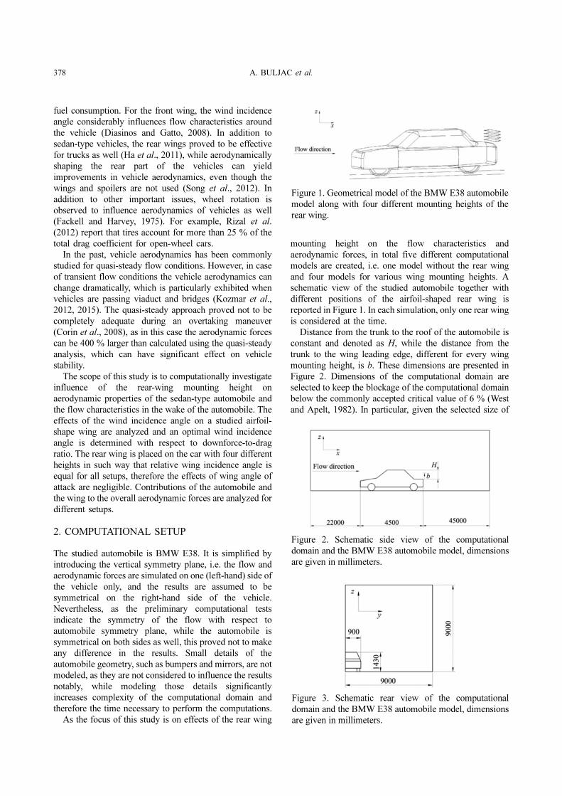
schematic view of the studied automobile together with
different positions of the airfoil-shaped rear wing is
reported in Figure 1. In each simulation, only one rear wing
is considered at the time.
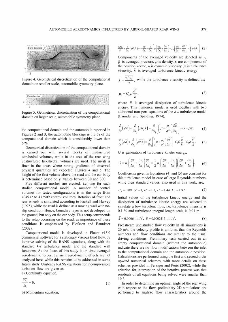
Distance from the trunk to the roof of the automobile is
constant and denoted as H, while the distance from the
trunk to the wing leading edge, different for every wing
mounting height, is b. These dimensions are presented in
Figure 2. Dimensions of the computational domain are
selected to keep the blockage of the computational domain
below the commonly accepted critical value of 6 % (West
and Apelt, 1982). In particular, given the selected size of
Figure 1. Geometrical model of the BMW E38 automobile
model along with four different mounting heights of the
rear wing.
Figure 2. Schematic side view of the computational
domain and the BMW E38 automobile model, dimensions
are given in millimeters.
Figure 3. Schematic rear view of the computational
domain and the BMW E38 automobile model, dimensions
are given in millimeters.
AUTOMOBILE AERODYNAMICS INFLUENCED BY AIRFOIL-SHAPED REAR WING 379
the computational domain and the automobile reported in
Figures 2 and 3, the automobile blockage is 1.3 % of the
computational domain which is considerably lower than
6 %.
Geometrical discretization of the computational domain
is carried out with several blocks of unstructured
tetrahedral volumes, while in the area of the rear wing
unstructured hexahedral volumes are used. The mesh is
finer in the areas where strong gradients of observed
physical quantities are expected, Figures 4 and 5. The
height of the first volume above the road and the car body
is determined based on y+ values between 30 and 300.
Five different meshes are created, i.e. one for each
studied computational model. A number of control
volumes for tested configurations is in the range from
404932 to 432509 control volumes. Rotation of front and
rear wheels is simulated according to Fackell and Harvey
(1975), while the road is defined as a moving wall with no-
slip condition. Hence, boundary layer is not developed on
the ground, but only on the car body. This setup corresponds
to the setup occurring on the road, as importance of these
conditions is emphasized by Elofsson and Bannister
(2002).
Computational model is developed in Fluent v15.0
commercial software for a stationary viscous fluid flow, by
iterative solving of the RANS equations, along with the
standard k-ε turbulence model and the standard wall
functions. As the focus of this study is on time averaged
aerodynamic forces, transient aerodynamic effects are not
analyzed here, while this remains to be addressed in some
future study. Unsteady RANS equations for incompressible
turbulent flow are given as;
a) Continuity equation,
(1)
b) Momentum equation,
(2)
Components of the averaged velocity are denoted as vi,
is averaged pressure, ρ is density, xi are components of
the position vector, μ is dynamic viscosity, μt is turbulence
viscosity, is averaged turbulence kinetic energy
while the turbulence viscosity is defined as;
(3)
where is averaged dissipation of turbulence kinetic
energy. This numerical model is used together with two
additional transport equations of the k-ε turbulence model
(Launder and Spalding, 1974),
(4)
(5)
G is generation of turbulence kinetic energy,
(6)
Coefficients given in Equations (4) and (5) are constant for
this turbulence model in case of large Reynolds numbers,
while their standard values, also used in this work, are,
(7)
Initial values of the turbulence kinetic energy and the
dissipation of turbulence kinetic energy are selected to
simulate a low turbulent flow, i.e. turbulence intensity is
0.1 % and turbulence integral length scale is 0.01 m,
m2/s2, m2/s3. (8)
Freestream undisturbed flow velocity in all simulations is
20 m/s, the velocity profile is uniform, thus the Reynolds
numbers and flow conditions are similar to the usual
driving conditions. Preliminary tests carried out in an
empty computational domain (without the automobile)
indicate there are no flow modifications between the inlet
to the computational domain and the automobile position.
Calculations are performed using the first and second order
upwind numerical schemes, with more details on these
schemes provided in Ferziger and Perić (2002), while the
criterion for interruption of the iterative process was that
residuals of all equations being solved were smaller than
10−4.
In order to determine an optimal angle of the rear wing
with respect to the flow, preliminary 2D simulations are
performed to analyze flow characteristics around the
j
j
0,v
x
∂=
∂
( ) j ji i i
j i t i j
j i j j i j i
2.
3
v vv v vpv v k
t x x x x x x x
ρρ μ μ ρ δ
⎡ ⎤⎛ ⎞ ⎛ ⎞∂ ∂∂ ∂ ∂∂ ∂ ∂+ = − + + + + −⎢ ⎥⎜ ⎟ ⎜ ⎟⎜ ⎟ ⎜ ⎟∂ ∂ ∂ ∂ ∂ ∂ ∂ ∂⎢ ⎥⎝ ⎠ ⎝ ⎠⎣ ⎦
p
k
i i' '
,2
v vk =
2
t µ,
kC=μ ρ
ε
ε
( ) ( ) t
j k
j j j
,
kk v k G
t x x x
μρ ρ μ ρε
σ
⎡ ⎤∂ ∂ ∂ ∂⎛ ⎞+ = + + −⎢ ⎥⎜ ⎟∂ ∂ ∂ ∂⎝ ⎠⎢ ⎥⎣ ⎦
( ) ( )2
tj 1 2ε
j j j
.v CG Ct x x x k k
⎡ ⎤∂ ∂ ∂ ∂⎛ ⎞+ = + − −⎢ ⎥⎜ ⎟∂ ∂ ∂ ∂⎝ ⎠⎢ ⎥⎣ ⎦
μ ε ε ερε ρ ε μ ρ
σ
j j ji i i i
t t
j i j j i j i
1.
2
v v vv v v vG
x x x x x x xµ µ
⎛ ⎞ ⎛ ⎞⎛ ⎞∂ ∂ ∂∂ ∂ ∂ ∂= + = + +⎜ ⎟ ⎜ ⎟⎜ ⎟⎜ ⎟ ⎜ ⎟⎜ ⎟∂ ∂ ∂ ∂ ∂ ∂ ∂⎝ ⎠ ⎝ ⎠⎝ ⎠
k
1 20.09, 1, 1.3, 1.44, 1.92.C C C
ε
μ= σ = σ = = =
0.0006k = 0.0002415ε =
Figure 4. Geometrical discretization of the computational
domain on smaller scale, automobile symmetry plane.
Figure 5. Geometrical discretization of the computational
domain on larger scale, automobile symmetry plane.
380 A. BULJAC et al.
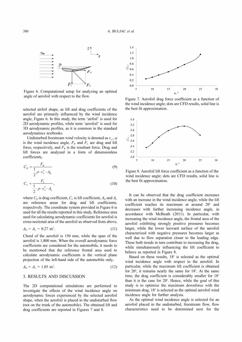
selected airfoil shape, as lift and drag coefficients of the
aerofoil are primarily influenced by the wind incidence
angle, Figure 6. In this study, the term ‘airfoil’ is used for
2D aerodynamic profiles, while term ‘aerofoil’ is used for
3D aerodynamic profiles, as it is common in the standard
aerodynamics textbooks.
Undisturbed freestream wind velocity is denoted as , αis the wind incidence angle, FD and FL are drag and lift
force, respectively, and FR is the resultant force. Drag and
lift forces are analyzed in a form of dimensionless
coefficients,
(9)
(10)
where CD is drag coefficient, CL is lift coefficient, AD and AL
are reference areas for drag and lift coefficients,
respectively. The coordinate system provided in Figure 6 is
used for all the results reported in this study. Reference area
used for calculating aerodynamic coefficients for aerofoil is
cross-sectional area of the aerofoil as observed from above,
AD = AL = 0.27 m2. (11)
Chord of the aerofoil is 150 mm, while the span of the
aerofoil is 1,800 mm. When the overall aerodynamic force
coefficients are considered for the automobile, it needs to
be mentioned that the reference frontal area used to
calculate aerodynamic coefficients is the vertical plane
projection of the left-hand side of the automobile only,
AD = AL = 1.05 m2. (12)
3. RESULTS AND DISCUSSION
The 2D computational simulations are performed to
investigate the effects of the wind incidence angle on
aerodynamic forces experienced by the selected aerofoil
shape, when the aerofoil is placed in the undisturbed flow
(not on the trunk of the automobile). The obtained lift and
drag coefficients are reported in Figures 7 and 8.
It can be observed that the drag coefficient increases
with an increase in the wind incidence angle, while the lift
coefficient reaches its maximum at around 20o and
decreases with further increasing incidence angle, in
accordance with McBeath (2011). In particular, with
increasing the wind incidence angle, the frontal area of the
aerofoil exhibiting strongly positive pressures becomes
larger, while the lower leeward surface of the aerofoil
characterized with negative pressures becomes larger as
well due to flow separation closer to the leading edge.
These both trends in turn contribute to increasing the drag,
while simultaneously influencing the lift coefficient to
behave as reported in Figure 8.
Based on these results, 18o is selected as the optimal
wind incidence angle with respect to the aerofoil. In
particular, while the maximum lift coefficient is obtained
for 20o, it remains nearly the same for 18o. At the same
time, the drag coefficient is considerably smaller for 18o
than it is the case for 20o. Hence, while the goal of this
study is to optimize the maximum downforce with the
minimum drag, 18o is selected as the optimal aerofoil wind
incidence angle for further analysis.
As the optimal wind incidence angle is selected for an
aerofoil placed in the undisturbed, freestream flow, flow
characteristics need to be determined next for the
v∞
D
D
2
D
1
2
FC
v A∞
=
⋅ ⋅ρ
L
L
2
L
,1
2
FC
v A∞
=
⋅ ⋅ ⋅ρ
Figure 6. Computational setup for analyzing an optimal
angle of aerofoil with respect to the flow.Figure 7. Aerofoil drag force coefficient as a function of
the wind incidence angle; dots are CFD results, solid line is
the best fit approximation.
Figure 8. Aerofoil lift force coefficient as a function of the
wind incidence angle; dots are CFD results, solid line is
the best fit approximation.
AUTOMOBILE AERODYNAMICS INFLUENCED BY AIRFOIL-SHAPED REAR WING 381
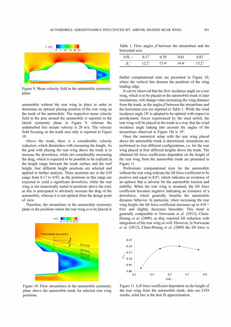
automobile without the rear wing in place in order to
determine an optimal placing position of the rear wing on
the trunk of the automobile. The respective mean velocity
field in the area around the automobile is reported in the
lateral symmetry plane in Figure 9, whereas the
undisturbed free stream velocity is 20 m/s. The velocity
field focusing on the trunk area only is reported in Figure
10.
Above the trunk, there is a considerable velocity
reduction, which diminishes with increasing the height. As
the goal with placing the rear wing above the trunk is to
increase the downforce, while not considerably increasing
the drag, which is expected to be possible to be realized in
the height range between the trunk surface and the roof
height, four different height positions are selected and
applied in further analysis. These positions are in the b/H
range from 0.17 to 0.83, as the positions in this range are
expected to yield a significant downforce, while the rear
wing is not numerically tested in positions above the roof,
as this is anticipated to adversely increase the drag of the
automobile, whereas it is not optimal from the design point
of view.
Therefore, the streamlines in the automobile symmetry
plane in the positions where the rear wing is to be placed in
further computational tests are presented in Figure 10,
where the vertical line denotes the positions of the wing
leading edge.
It can be observed that the flow incidence angle on a rear
wing, which is to be placed on the automobile trunk in later
simulations, will change when increasing the wing distance
from the trunk, as the angles β between the streamlines and
the horizontal axis are reported in Table 1. While the wind
incidence angle 18o is adopted to be optimal with respect to
aerodynamic forces experienced by the used airfoil, the
rear wing will be placed at the trunk in a way that the wind
incidence angle (taking into account the angles of the
streamlines observed in Figure 10) is 18o.
Once the numerical setup with the rear wing placed
above the automobile trunk is determined, simulations are
performed in four different configurations, i.e. for the rear
wing placed at four different heights above the trunk. The
obtained lift force coefficients dependent on the height of
the rear wing from the automobile trunk are presented in
Figure 11.
Preliminary computational tests for the automobile
without the rear wing indicate the lift force coefficient to be
positive and equal to 0.07, which indicates an existence of
an upforce that is adverse for the automobile traction and
stability. When the rear wing is mounted, the lift force
coefficient becomes negative indicating an existence of a
downforce, which generally benefits the automobile
dynamic behavior. In particular, when increasing the rear
wing height, the lift force coefficient increases up to b/H =
0.61 and slightly decreases thereafter. This trend is
generally comparable to Norwazan et al. (2012), Chien-
Hsiung et al. (2009), as they reported lift reduction with
integration of the rear wing as well. However, in Norwazan
et al. (2012), Chien-Hsiung et al. (2009) the lift force is
Figure 9. Mean velocity field in the automobile symmetry
plane.
Figure 10. Flow streamlines in the automobile symmetry
plane above the automobile trunk for selected rear wing
positions.
Table 1. Flow angles β between the streamlines and the
horizontal axis.
b/H, − 0.17 0.39 0.61 0.83
β, o 12.2o 13.4o 14.4o 15.2o
Figure 11. Lift force coefficient dependent on the height of
the rear wing from the automobile trunk; dots are CFD
results, solid line is the best fit approximation.
382 A. BULJAC et al.
directed upwards in all configurations, while in the present
study a downforce that enhances automobile dynamics
even more is obtained, as a result of an optimization of the
flow incidence angle onto the rear wing.
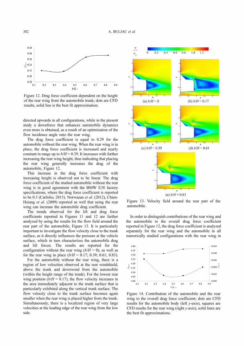
The drag force coefficient is equal to 0.29 for the
automobile without the rear wing. When the rear wing is in
place, the drag force coefficient is increased and nearly
constant in range up to b/H = 0.39. It increases with further
increasing the rear wing height, thus indicating that placing
the rear wing generally increases the drag of the
automobile, Figure 12.
This increase in the drag force coefficient with
increasing height is observed not to be linear. The drag
force coefficient of the studied automobile without the rear
wing is in good agreement with the BMW E38 factory
specifications, where the drag force coefficient is reported
to be 0.3 (Carfolio, 2015). Norwazan et al. (2012), Chien-
Hsiung et al. (2009) reported as well that using the rear
wing can increase the automobile drag coefficient.
The trends observed for the lift and drag force
coefficients reported in Figures 11 and 12 are further
analyzed by using the results for the flow field around the
rear part of the automobile, Figure 13. It is particularly
important to investigate the flow velocity close to the trunk
surface, as it directly influences the pressure at the vehicle
surface, which in turn characterizes the automobile drag
and lift forces. The results are reported for the
configuration without the rear wing (b/H = 0), as well as
for the rear wing in place (b/H = 0.17; 0.39; 0.61; 0.83).
For the automobile without the rear wing, there is a
region of low velocities observed at the rear windshield,
above the trunk and downwind from the automobile
(within the height range of the trunk). For the lowest rear
wing position (b/H = 0.17), the flow velocity increases in
the area immediately adjacent to the trunk surface that is
particularly exhibited along the vertical trunk surface. The
flow velocity close to the trunk surface becomes again
smaller when the rear wing is placed higher from the trunk.
Simultaneously, there is a localized region of very large
velocities at the leading edge of the rear wing from the low
side.
In order to distinguish contributions of the rear wing and
the automobile to the overall drag force coefficient
reported in Figure 12, the drag force coefficient is analyzed
separately for the rear wing and the automobile in all
numerically studied configurations with the rear wing in
Figure 12. Drag force coefficient dependent on the height
of the rear wing from the automobile trunk; dots are CFD
results, solid line is the best fit approximation.
Figure 13. Velocity field around the rear part of the
automobile.
Figure 14. Contribution of the automobile and the rear
wing to the overall drag force coefficient; dots are CFD
results for the automobile body (left y-axis), squares are
CFD results for the rear wing (right y-axis), solid lines are
the best fit approximations.
AUTOMOBILE AERODYNAMICS INFLUENCED BY AIRFOIL-SHAPED REAR WING 383
place, Figure 14. Both drag coefficients are calculated
using the same reference area, as it is used for calculation
of overall force coefficients.
The results indicate that the contribution of the
automobile body to the overall drag force coefficient is
dominant with respect to the wing contribution. The
contribution of the automobile body to the overall drag is
smaller and nearly constant for the wing mounting heights
b/H = 0.17 and 0.39, while it is increased for two higher
rear wing positions, i.e. for b/H = 0.61 and 0.83. Those
results combined yield an optimal rear wing height of b/H
= 0.39 with respect to the drag force.
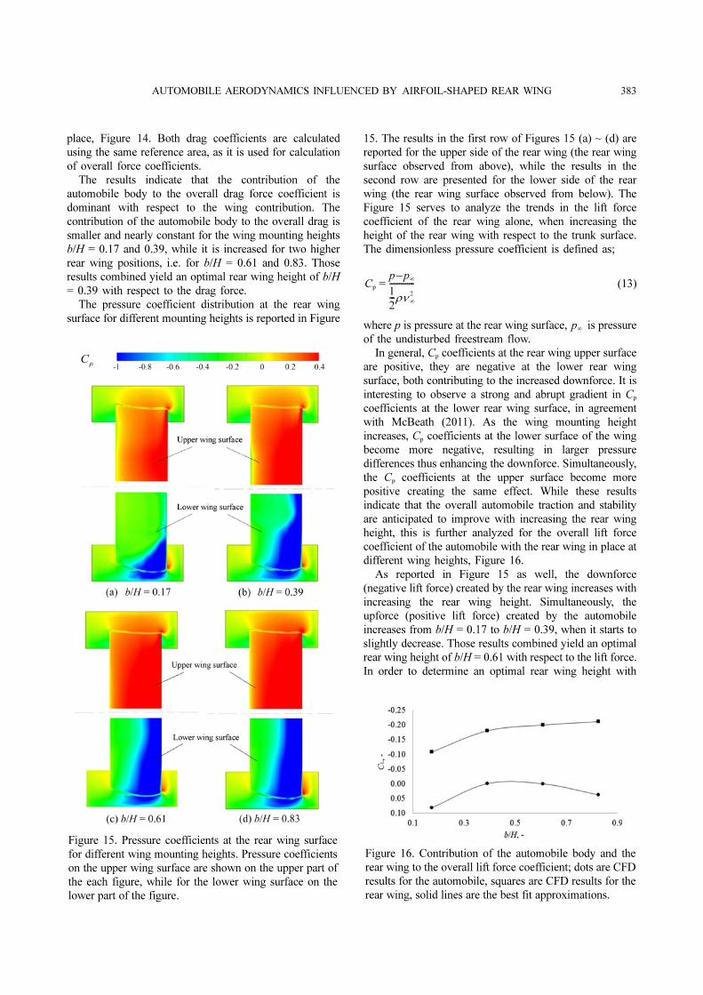
The pressure coefficient distribution at the rear wing
surface for different mounting heights is reported in Figure
15. The results in the first row of Figures 15 (a) ~ (d) are
reported for the upper side of the rear wing (the rear wing
surface observed from above), while the results in the
second row are presented for the lower side of the rear
wing (the rear wing surface observed from below). The
Figure 15 serves to analyze the trends in the lift force
coefficient of the rear wing alone, when increasing the
height of the rear wing with respect to the trunk surface.
The dimensionless pressure coefficient is defined as;
(13)
where p is pressure at the rear wing surface, is pressure
of the undisturbed freestream flow.
In general, Cp coefficients at the rear wing upper surface
are positive, they are negative at the lower rear wing
surface, both contributing to the increased downforce. It is
interesting to observe a strong and abrupt gradient in Cp
coefficients at the lower rear wing surface, in agreement
with McBeath (2011). As the wing mounting height
increases, Cp coefficients at the lower surface of the wing
become more negative, resulting in larger pressure
differences thus enhancing the downforce. Simultaneously,
the Cp coefficients at the upper surface become more
positive creating the same effect. While these results
indicate that the overall automobile traction and stability
are anticipated to improve with increasing the rear wing
height, this is further analyzed for the overall lift force
coefficient of the automobile with the rear wing in place at
different wing heights, Figure 16.
As reported in Figure 15 as well, the downforce
(negative lift force) created by the rear wing increases with
increasing the rear wing height. Simultaneously, the
upforce (positive lift force) created by the automobile
increases from b/H = 0.17 to b/H = 0.39, when it starts to
slightly decrease. Those results combined yield an optimal
rear wing height of b/H = 0.61 with respect to the lift force.
In order to determine an optimal rear wing height with
Cp = p p
∞–
1
2---ρν
∞
2
-------------
p∞
Figure 15. Pressure coefficients at the rear wing surface
for different wing mounting heights. Pressure coefficients
on the upper wing surface are shown on the upper part of
the each figure, while for the lower wing surface on the
lower part of the figure.
Figure 16. Contribution of the automobile body and the
rear wing to the overall lift force coefficient; dots are CFD
results for the automobile, squares are CFD results for the
rear wing, solid lines are the best fit approximations.
384 A. BULJAC et al.
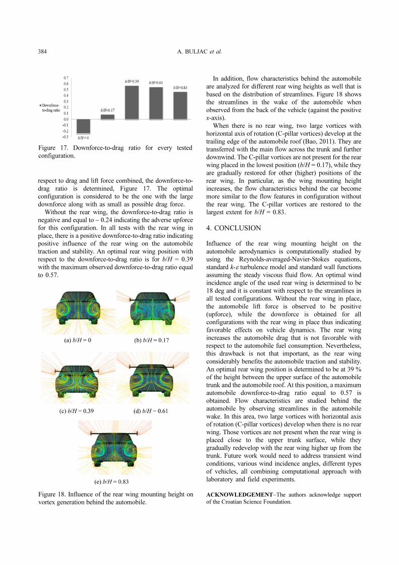
respect to drag and lift force combined, the downforce-to-
drag ratio is determined, Figure 17. The optimal
configuration is considered to be the one with the large
downforce along with as small as possible drag force.
Without the rear wing, the downforce-to-drag ratio is
negative and equal to − 0.24 indicating the adverse upforce
for this configuration. In all tests with the rear wing in
place, there is a positive downforce-to-drag ratio indicating
positive influence of the rear wing on the automobile
traction and stability. An optimal rear wing position with
respect to the downforce-to-drag ratio is for b/H = 0.39
with the maximum observed downforce-to-drag ratio equal
to 0.57.
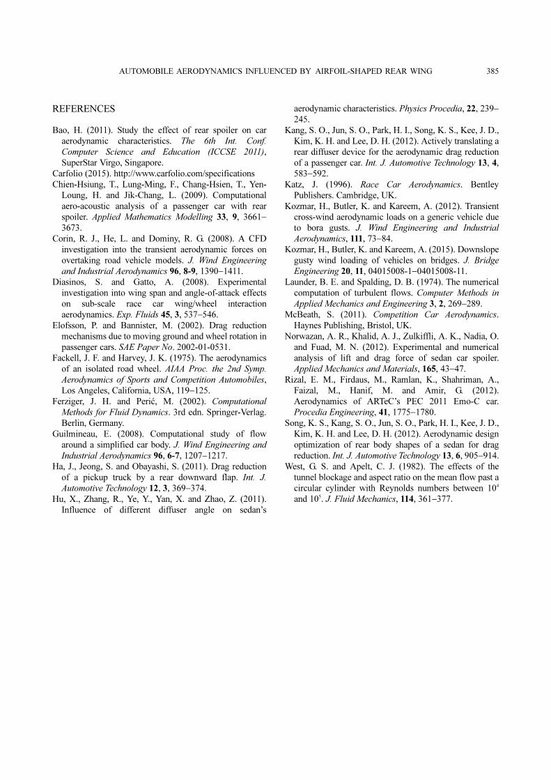
In addition, flow characteristics behind the automobile
are analyzed for different rear wing heights as well that is
based on the distribution of streamlines. Figure 18 shows
the streamlines in the wake of the automobile when
observed from the back of the vehicle (against the positive
x-axis).
When there is no rear wing, two large vortices with
horizontal axis of rotation (C-pillar vortices) develop at the
trailing edge of the automobile roof (Bao, 2011). They are
transferred with the main flow across the trunk and further
downwind. The C-pillar vortices are not present for the rear
wing placed in the lowest position (b/H = 0.17), while they
are gradually restored for other (higher) positions of the
rear wing. In particular, as the wing mounting height
increases, the flow characteristics behind the car become
more similar to the flow features in configuration without
the rear wing. The C-pillar vortices are restored to the
largest extent for b/H = 0.83.
4. CONCLUSION
Influence of the rear wing mounting height on the
automobile aerodynamics is computationally studied by
using the Reynolds-averaged-Navier-Stokes equations,
standard k-ε turbulence model and standard wall functions
assuming the steady viscous fluid flow. An optimal wind
incidence angle of the used rear wing is determined to be
18 deg and it is constant with respect to the streamlines in
all tested configurations. Without the rear wing in place,
the automobile lift force is observed to be positive
(upforce), while the downforce is obtained for all
configurations with the rear wing in place thus indicating
favorable effects on vehicle dynamics. The rear wing
increases the automobile drag that is not favorable with
respect to the automobile fuel consumption. Nevertheless,
this drawback is not that important, as the rear wing
considerably benefits the automobile traction and stability.
An optimal rear wing position is determined to be at 39 %
of the height between the upper surface of the automobile
trunk and the automobile roof. At this position, a maximum
automobile downforce-to-drag ratio equal to 0.57 is
obtained. Flow characteristics are studied behind the
automobile by observing streamlines in the automobile
wake. In this area, two large vortices with horizontal axis
of rotation (C-pillar vortices) develop when there is no rear
wing. Those vortices are not present when the rear wing is
placed close to the upper trunk surface, while they
gradually redevelop with the rear wing higher up from the
trunk. Future work would need to address transient wind
conditions, various wind incidence angles, different types
of vehicles, all combining computational approach with
laboratory and field experiments.
ACKNOWLEDGEMENT−The authors acknowledge support
of the Croatian Science Foundation.
Figure 17. Downforce-to-drag ratio for every tested
configuration.
Figure 18. Influence of the rear wing mounting height on
vortex generation behind the automobile.
AUTOMOBILE AERODYNAMICS INFLUENCED BY AIRFOIL-SHAPED REAR WING 385
REFERENCES
Bao, H. (2011). Study the effect of rear spoiler on car
aerodynamic characteristics. The 6th Int. Conf.
Computer Science and Education (ICCSE 2011),
SuperStar Virgo, Singapore.
Carfolio (2015). http://www.carfolio.com/specifications
Chien-Hsiung, T., Lung-Ming, F., Chang-Hsien, T., Yen-
Loung, H. and Jik-Chang, L. (2009). Computational
aero-acoustic analysis of a passenger car with rear
spoiler. Applied Mathematics Modelling 33, 9, 3661−
3673.
Corin, R. J., He, L. and Dominy, R. G. (2008). A CFD
investigation into the transient aerodynamic forces on
overtaking road vehicle models. J. Wind Engineering
and Industrial Aerodynamics 96, 8-9, 1390−1411.
Diasinos, S. and Gatto, A. (2008). Experimental
investigation into wing span and angle-of-attack effects
on sub-scale race car wing/wheel interaction
aerodynamics. Exp. Fluids 45, 3, 537−546.
Elofsson, P. and Bannister, M. (2002). Drag reduction
mechanisms due to moving ground and wheel rotation in
passenger cars. SAE Paper No. 2002-01-0531.
Fackell, J. F. and Harvey, J. K. (1975). The aerodynamics
of an isolated road wheel. AIAA Proc. the 2nd Symp.
Aerodynamics of Sports and Competition Automobiles,
Los Angeles, California, USA, 119−125.
Ferziger, J. H. and Perić, M. (2002). Computational
Methods for Fluid Dynamics. 3rd edn. Springer-Verlag.
Berlin, Germany.
Guilmineau, E. (2008). Computational study of flow
around a simplified car body. J. Wind Engineering and
Industrial Aerodynamics 96, 6-7, 1207−1217.
Ha, J., Jeong, S. and Obayashi, S. (2011). Drag reduction
of a pickup truck by a rear downward flap. Int. J.
Automotive Technology 12, 3, 369−374.
Hu, X., Zhang, R., Ye, Y., Yan, X. and Zhao, Z. (2011).
Influence of different diffuser angle on sedan’s
aerodynamic characteristics. Physics Procedia, 22, 239−
245.
Kang, S. O., Jun, S. O., Park, H. I., Song, K. S., Kee, J. D.,
Kim, K. H. and Lee, D. H. (2012). Actively translating a
rear diffuser device for the aerodynamic drag reduction
of a passenger car. Int. J. Automotive Technology 13, 4,
583−592.
Katz, J. (1996). Race Car Aerodynamics. Bentley
Publishers. Cambridge, UK.
Kozmar, H., Butler, K. and Kareem, A. (2012). Transient
cross-wind aerodynamic loads on a generic vehicle due
to bora gusts. J. Wind Engineering and Industrial
Aerodynamics, 111, 73−84.
Kozmar, H., Butler, K. and Kareem, A. (2015). Downslope
gusty wind loading of vehicles on bridges. J. Bridge
Engineering 20, 11, 04015008-1−04015008-11.
Launder, B. E. and Spalding, D. B. (1974). The numerical
computation of turbulent flows. Computer Methods in
Applied Mechanics and Engineering 3, 2, 269−289.
McBeath, S. (2011). Competition Car Aerodynamics.
Haynes Publishing, Bristol, UK.
Norwazan, A. R., Khalid, A. J., Zulkiffli, A. K., Nadia, O.
and Fuad, M. N. (2012). Experimental and numerical
analysis of lift and drag force of sedan car spoiler.
Applied Mechanics and Materials, 165, 43−47.
Rizal, E. M., Firdaus, M., Ramlan, K., Shahriman, A.,
Faizal, M., Hanif, M. and Amir, G. (2012).
Aerodynamics of ARTeC’s PEC 2011 Emo-C car.
Procedia Engineering, 41, 1775−1780.
Song, K. S., Kang, S. O., Jun, S. O., Park, H. I., Kee, J. D.,
Kim, K. H. and Lee, D. H. (2012). Aerodynamic design
optimization of rear body shapes of a sedan for drag
reduction. Int. J. Automotive Technology 13, 6, 905−914.
West, G. S. and Apelt, C. J. (1982). The effects of the
tunnel blockage and aspect ratio on the mean flow past a
circular cylinder with Reynolds numbers between 104
and 105. J. Fluid Mechanics, 114, 361−377.