AUTOMATION OF PROTOTYPE SOLID WASTE MANAGEMENT SYSTEM FOR
101
AUTOMATION OF PROTOTYPE SOLID WASTE MANAGEMENT SYSTEM FOR LONG TERM NASA SPACE MISSIONS By SUNEET LUNIYA A THESIS PRESENTED TO THE GRADUATE SCHOOL OF THE UNIVERSITY OF FLORIDA IN PARTIAL FULFILLMENT OF THE REQUIREMENTS FOR THE DEGREE OF MASTER OF SCIENCE UNIVERSITY OF FLORIDA 2005
Transcript of AUTOMATION OF PROTOTYPE SOLID WASTE MANAGEMENT SYSTEM FOR

AUTOMATION OF PROTOTYPE SOLID WASTE MANAGEMENT SYSTEM FOR
LONG TERM NASA SPACE MISSIONS
By
SUNEET LUNIYA
A THESIS PRESENTED TO THE GRADUATE SCHOOL OF THE UNIVERSITY OF FLORIDA IN PARTIAL FULFILLMENT
OF THE REQUIREMENTS FOR THE DEGREE OF MASTER OF SCIENCE
UNIVERSITY OF FLORIDA
2005

Copyright 2005
by
Suneet Luniya

To my parents who have always been supportive of all my work …

ACKNOWLEDGMENTS
I would like thank the many individuals that have contributed to make this project a
success and my educational experience so enjoyable. Specifically, I would like to
express my great appreciation to Dr. Arthur A. Teixeira, my academic advisor and
committee chair, for his continual support and guidance during my time at the University
of Florida. I would like to give special thanks to Dr. Thomas F. Burks for his help in
getting my work started and putting me on the right track. I also owe a lot of gratitude to
Dr. John K. Schueller, my advisor for my concurrent degree in mechanical engineering,
for his immense help at various points during my work. I would like to thank Dr. John
M. Owens for his insightful ideas and hands-on support through out my work. In
addition, I would like to thank Mr. Bob Tonkinson for assisting me with mechanical
issues.
On a more personal note I would like to thank my parents and family; without
them, this would never have been possible. I would also like to thank my friends at the
University of Florida who have directly and indirectly contributed to my work here.
iv

TABLE OF CONTENTS page
ACKNOWLEDGMENTS ................................................................................................. iv
LIST OF TABLES............................................................................................................ vii
LIST OF FIGURES ......................................................................................................... viii
ABBREVIATIONS AND ACRONYMS............................................................................x
ABSTRACT...................................................................................................................... xii
CHAPTER
1 INTRODUCTION ........................................................................................................1
1.1 Background and Justification .................................................................................1 1.2 Objectives ...............................................................................................................2 1.3 Thesis Organization ................................................................................................3
2 LITERATURE REVIEW .............................................................................................4
2.1 Overview of ALS Mission of NASA......................................................................4 2.2 Anaerobic Digestion and SEBAC ..........................................................................9
2.2.1 Anaerobic Digestion for Waste Management ..............................................9 2.2.2 SEBAC Process ..........................................................................................10
2.3 SEBAC for NASA ALS Mission .........................................................................12 2.3.1 Research Program at the University of Florida ..........................................12
2.3.1.1 Laboratory studies-Feedstock selection and analysis.......................12 2.3.1.2 SEBAC concept for space-Design ...................................................15 2.3.1.3 Bench scale studies...........................................................................16 2.3.1.4 Prototype system design and construction .......................................17 2.3.1.5 Prototype digester start-up and operation.........................................18
2.3.2 Proposed Improvements .............................................................................19
3 PROCEDURE AND METHODOLOGY...................................................................20
3.1 Original Reactor System Description (SEBAC II) ...............................................20 3.2 Design Modifications on SEBAC II .....................................................................25
3.2.1 Pump and Pump Manifold Line .................................................................25
v

3.2.2 Gas Liquid Separator ..................................................................................26 3.2.3 Flow Reversal System ................................................................................27
3.3 Instrumentation .....................................................................................................29 3.3.1 Data Acquisition System ............................................................................30 3.3.2 Sensor – Gas Flow......................................................................................30
3.3.2.1 Principle of operation .......................................................................31 3.3.2.2 Calibration of gas meter ...................................................................32 3.3.2.3 Connection to data acquisition .........................................................34
3.3.3 Sensor-Pressure ..........................................................................................35 3.3.3.1 Principle of operation .......................................................................35 3.3.3.2 Calibration of pressure sensor ..........................................................35 3.3.3.3 Connection to data acquisition system .............................................38
3.3.4 Automatic Actuation of Valves ..................................................................39 3.4 Process Control System ........................................................................................41
4 RESULTS AND DISCUSSION.................................................................................45
4.1 Feedstock Properties and Processing-BMP Analysis ...........................................45 4.1.1 Determination of Ym, k..............................................................................46 4.1.2 BMP for the Experimental Runs ................................................................47
4.2 Analysis of Process Control System.....................................................................48 4.2.1 Automatic Actuation of Valves ..................................................................51 4.2.2 Effect of Flow Reversal on Biogas Production ..........................................53 4.2.3 Effect of Flow Reversal on Pressure in Reactor.........................................54
4.3 Performance of the System...................................................................................55
5 CONCLUSIONS AND FUTURE WORK.................................................................61
5.1 Recommendations.................................................................................................62 5.2 Suggestions for Future Work................................................................................62
APPENDIX
A OPERATION MANUAL FOR MODIFIED SEBAC II ............................................64
B SOURCE CODE FOR PROCESS CONTROL ALGORITHM.................................72
LIST OF REFERENCES...................................................................................................85
BIOGRAPHICAL SKETCH .............................................................................................88
vi

LIST OF TABLES
Table page 2-1 List of subsystems of a life support system (LSS) based on ALS Project .................5
2-2 Components of the waste stream for 6-person crew during a 600-day long space missions......................................................................................................................8
3-1 SEBAC-II prototype design specifications ..............................................................22
4-1 TS, VS, k and Ym for components of simulated feedstock for ALS missions........46
4-2 Methane yield estimate for the feedstock of 3 experimental runs............................48
4-3 Equivalent systems mass (ESM) for SEBAC system ..............................................52
A-1 Operation sequence for SEBAC...............................................................................66
A-2 Valve positions for different operating sequences ...................................................66
vii

LIST OF FIGURES
Figure page 2-1 Closed advanced life support system .........................................................................6
2-2 Schematic of the sequential batch anaerobic composting (SEBAC) process ..........11
2-3 Conceptual design of Sequential Batch Anaerobic Composting (SEBAC) system for space missions ....................................................................................................15
2-4 Bench-scale SEBAC prototype with two reactors and a reservoir...........................17
2-5 Prototype 5-reactor SEBAC-II system for six-person crew on 600 day NASA space mission............................................................................................................18
3-1 Schematic of SEBAC II prototype system...............................................................21
3-2 Exploded view of a single reactor ............................................................................22
3-3 Piping diagram of SEBAC II prototype system .......................................................24
3-4 Piping diagram of gas-liquid separator circuit .........................................................27
3-5 Direction of flow in closed loop formed by 3 way valves .......................................29
3-6 Construction of a gas flow meter .............................................................................31
3-7 Calibration column for calibration of a tipping bucket gas flow meter ...................32
3-8 Pickup leads for the connection with data-logger ....................................................34
3-9 Calibration apparatus for the calibration of pressure sensor ....................................36
3-10 Calibration curve for pressure sensor – Pressure vs. voltage ratio...........................37
3-11 Circuit diagram for connecting pressure sensors to data acquisition system...........39
3-12 Electrical wiring diagram for 115 VAC actuators ...................................................40
3-13 Circuit diagram for connection of the pressure sensors to data acquisition.............41
3-14 Flow chart for control algorithm ..............................................................................43
viii

3-15 Piping and instrumentation diagram for the modified SEBAC II prototype system.......................................................................................................................44
4-1 Components of the simulated feedstock for ALS mission.......................................46
4-2 Linear fit for BMP analysis of dog food and wheat straw .......................................47
4-3 Components of a general control system .................................................................49
4-4 Effect of flow reversal on the biogas generation......................................................53
4-5 Effect of flow reversal on the reactor pressure.........................................................54
4-6 Performance of modified SEBAC II system for experimental run with unidirectional flow ...................................................................................................56
4-7 Performance of modified SEBAC II system for experimental run with periodic flow reversal .............................................................................................................57
4-8 Performance of modified SEBAC II system for experimental run with adaptive control system ..........................................................................................................58
4-9 Comparative performance for three runs on modified SEBAC II system ...............60
A-1 Notation used to denote various components of modified SEBAC II .....................65
A-2 Wiring diagram for connection to the data acquisition ............................................70
ix

KEY TO SYMBOLS ABBREVIATIONS AND ACRONYMS
ALS = Advance life support system
ARS = Air revitalization system
ATCS = Active thermal control system
BVAD = Baseline values and assumptions document
BMP = Biochemical methane potential
BPS = Biogas production system
CH4 = (Chemical formula for methane)
ECLSS = Environmental control and life support system
ESCSTC = Environmental systems commercial space technology center
ESM = Equivalent systems mass
EVA = Extra vehicular activity
FPS = Food production system
GC = Gas chromatograph
HAS = Human accommodation system
HSLAD = High solids leachbed anaerobic digestion
ICS = Integrated control system
IFAS = Institute of food and agricultural sciences
ISS = International space station
IVA = Internal vehicular activity
LSS = Life support system
x

NASA = National aeronautics and space administration
SEBAC = Sequential batch anaerobic composting
SIMA = Systems integration, modeling and analysis
SPS = Solids processing system
SWM = Solid waste management
SWRS = Solid waste recovery system
TCS = Thermal control system
TRL = Test readiness level
TS = Total solids
VOA = Volatile organic acids
VFA = Volatile fatty acids
VS = Volatile solids
WRS = Water recovery system
xi

Abstract of Thesis Presented to the Graduate School
of the University of Florida in Partial Fulfillment of the Requirements for the Degree of Master of Science
AUTOMATION OF PROTOTYPE SOLID WASTE MANAGEMENT SYSTEM FOR LONG TERM NASA SPACE MISSIONS
By
Suneet Luniya
August 2005
Chair: Arthur A. Teixeira Major Department: Agricultural and Biological Engineering
It is the intended long-term objective of the National Aeronautics and Space
Administration (NASA) to establish a human presence in space. Utilizing closed-loop
advanced life support technologies will increase the autonomy of such missions by
reducing mass, power, and volume necessary for human support. The strategy is to
develop regenerative physicochemical and biological technologies that will reduce the
system’s mass, power and volume requirements on the entire mission. To have a truly
closed-loop system, it is necessary to produce and process food and recover resources
from wastes while providing clean air and water.
Sequential batch anaerobic composting (SEBAC) technology, developed and
patented by the University of Florida for odorless bioconversion of organic solid wastes
to methane and compost by anaerobic digestion, is proposed to potentially serve as the
principal organic solid waste management subsystem component in a bio-regenerative
advanced life support (ALS) system. The system consists of five reactors and two gas-
xii

liquid separators designed for operation under closed conditions in micro-gravity. During
any week of operation, one reactor is being used for feed collection and compaction,
three for stage-wise anaerobic composting, and one for post-treatment by aerobic
stabilization while simultaneously serving as a bio-filter in the pretreatment of cabin air
within the air revitalization subsystem.
This work reports on design improvements made to this full-scale prototype
designed to support a 6-person crew on long-term space missions. The thesis describes
the implementation of the control system for flow reversal of leachate through the system
to accomplish higher efficiency and minimize channeling of leachate through feedstock
beds during pressurized pumping operations. With the flow reversal system faster
reaction kinetics were obtained. Maximum biogas generation rate for the system with
flow reversal and process control system was 1.96 N L per liter reactor volume per day as
compared to 0.3 N L per liter reactor volume per day for the original system. The time
for digestion was reduced from 60 days to 14 days. Design of a control system to
automate the operation of the system by use of automatic actuation for the valves for flow
reversal to reduce the crew time spent on the operation of the system will also be
presented.
xiii

CHAPTER 1 INTRODUCTION
1.1 Background and Justification
Future mission goals of NASA involve long duration human missions. Advanced
life support systems (ALS) will be required for such space missions. Focus of such a
mission is on a 600-day planetary stay, which would require growth of plants to supply
food as well as to regenerate oxygen. Solid wastes generated in such ALS system will
include dry human wastes, inedible plant residues, trash, packaging material, paper, tape,
filters, and other miscellaneous wastes.1 A system based on anaerobic digestion of
organic waste into compost and methane is proposed to potentially serve as the principal
solid waste management (SWM) component in a bio-regenerative ALS system for long-
range NASA space missions and planetary bases.
The process, called Sequential batch anaerobic composting (SEBAC) was patented
by the University of Florida, 2 and was originally designed for terrestrial operation with
high solids feeds, such as municipal solid waste. For that application, gravity was relied
upon to bring cascading liquid leachate (containing the bacteria) in contact with the
organic feedstock.3, 4 In addition, bulk density of solid wastes in the leachbed was kept
low to enhance the leachate percolation rates. Operation under micro-gravity for space
applications will require modifying the original design to recycle leachate under flooded
operation using forced pumping without dependence upon gravity.
Since leachate flow rate will not be dependent on gravity, higher solid waste bulk
density in the leachbed can be used to increase the loading rate and reduce the reactor
1

2
size and system footprint. The recycling of leachate through external gas-liquid
separators could accommodate vortex gas/liquid separation systems.
Previous work resulted in development of a preliminary design for a full-scale
prototype by sizing the reactors, external leachate tanks, plumbing, pumps, and energy
demand; examining spatial arrangement; and performing a systems analysis which
included equivalent mass calculations. From the initial experimental runs it was evident
that modifications were necessary for proper operation of the prototype. It was expected
that even higher conversion rates and more balanced operating pressures would be
obtained if proper flow of leachate through the system were achieved. It was also
apparent that operating performance data would have to be measured, monitored and
recorded automatically in order to effectively study the effects of changes in operating
parameters on the system performance.
Equivalent systems mass (ESM) is a technique by which several physical quantities
that describe a system or subsystem can be reduced to a single physical parameter-mass.5
The technology with the lowest ESM value is the most cost effective option for the
mission under consideration, provided the options have the same function reliability. The
crew time is one of the important factors under consideration in calculations of equivalent
system mass. To demonstrate the SEBAC as a feasible system, its operation with
minimal use of crew time is an important consideration. Design of a control system to
automate the operation of the system by use of automatic actuation for the valves for flow
reversal will reduce the crew time spent on the operation of the system and hence reduce
the equivalent systems mass.
1.2 Objectives
Therefore, the objectives of this work were to

3
• Develop a process control system for flow reversal of leachate through the system during pressurized pumping operations
• Implement design improvements by installing valves, actuators, extra pump and gas liquid separators to achieve proper operation of the new design of the prototype
• Install instrumentation and implement techniques for monitoring and control of the system
1.3 Thesis Organization
This thesis is divided into five chapters.
Following this chapter, the second chapter, Review of Literature, deals with the
literature review and past work done in this area. The third chapter, Procedure and
Methodology, involves description of the methods used to solve the given problem. It
lists the assumptions made during the entire analysis and describes the procedures
followed during the implementation.
The fourth chapter, Results and Discussions, describe the results that were obtained
and fifth chapter, Conclusions and Future work, discusses the future work that is possible
in this area.

CHAPTER 2 LITERATURE REVIEW
2.1 Overview of ALS Mission of NASA
When humans set out on long duration missions such as the establishment of bases
on the lunar surface or travel to Mars for exploration, they will continue to need food,
water and air. For these long duration missions it may not be economical or practical to
supply basic life support elements from Earth. The National Aeronautics and Space
Administration (NASA) and the space community are developing systems to purify their
water supply, regenerate oxygen and remove undesirable components of the air as a part
of the NASA advanced life support system (ALS) program. Such a system would be a
closed loop system in which the growth of plants would contribute to the life support
functions. It would provide food from crop plants and would contribute to water
purification, air revitalization and the processing of waste materials. Thus it is essential
to develop a closed-loop life support system that relies on minimal or no re-supply from
earth, with all systems operating under the restrictions of minimizing volume, mass,
energy, and labor.
The goal of the ALS program is to provide life support self-sufficiency for human
beings to carry out research and exploration safely and productively in space for benefits
on Earth and to open the door for extended on-orbit stays and planetary exploration. The
life support subsystems and the subsystem and external interface relationships for the
ALS project are defined in Table 2-1 below 6 and a schematic block diagram of the
4

5
subsystems forming a closed loop ALS system is shown in Figure 2-1. A list of all
acronyms and symbols has been included in key to symbols section.
Table 2-1. List of subsystems of a life support system (LSS) based on ALS Project.6 Subsystem Description Air Revitalization (ARS)
The ARS maintains the vehicle cabin gases, including the overall composition and atmospheric pressure
Water Recovery (WRS)
The WRS provides water at the appropriate purity for crew consumption and hygiene
Biomass Production (BPS)
The BPS provides raw agricultural products to the FPS while regenerating air and water
Food Processing (FPS)
The FPS transforms raw or bulk agricultural products into foodstuffs
Solids Processing (SPS)
The SPS handles solid waste produced anywhere in the LSS, including packaging, human wastes, and brines from other subsystems such as the WRS. The SPS may sterilize and store the waste, or reclaim LSS commodities, depending on the LSS closure and/or mission duration
Thermal Control (TCS)
The TCS is responsible for maintaining cabin temperature and humidity within appropriate bounds and for rejecting the collected waste heat to the environment
Integrated Control (ICS)
The ICS provides appropriate control for the LSS
Human Accommodations (HAS)
The HAS is responsible for the crew cabin layout, crew clothing, and the crew’s interaction with the LSS
Mission duration and the crew size will be the determining factors that affect
analyses and models by changing the weighting of the various pieces of the system in
terms of time dependent items, equipment design, and infrastructure cost. To provide a
baseline framework for research activities, some assumptions have been made regarding
the duration of mission, keeping in mind reducing the amount of propellant needed to
move hardware and people from one planet to another (propellant mass typically being
the single largest element of these missions) and extending the amount of time the crew
spends conducting useful investigations on the surface of Mars 7.

6
Res
idue
,C
O2,
Nu t
rien t
Wat
erSolids Treatment
Residue
BiomassProduction
Food Consumption
LiquidWaste
TreatmentTo BiomassProduction
Struvite
NH3
Potable H2O
NH3 (urine)
Air Treatment
Cabin Air
NH4 +
CO2, H2O
Paper
ProcessingGrey Water
=compost
H2, CO2
CH4, H2O
Return to cabin air
Food Processing
Figure 2-1. Closed advanced life support system
For such long term missions, the duration of mission is assumed to be 3 years. The
interplanetary transit time is assumed to be 180 days, while 600 days would be devoted to
surface missions exploring the surface of Mars before returning to Earth. The crew team
of six persons is assumed for each trip involved in the reference missions of ALS metric
baseline.8
To have a truly closed-loop system, it is necessary to produce and process food and
recover resources from wastes while providing clean air and water. Losses of resources
vital to life support due to wastes (i.e. consumables) that cannot be processed and
recovered will require re-supply. A loss in essential life-supporting elements could
jeopardize crew performance and well being, whereas any re-supply from Earth will be
cost prohibitive. Thus, resource recovery from wastes becomes a critical component to
closure in ALS systems.7

7
Currently, international space station (ISS) has no solid waste management (SWM)
program. All trash are placed in a disposable trash vehicle and burned on re-entry or
brought back to Earth for processing. Concerns over planetary protection and resource
recovery have lead to formation of a SWM group for long-term and futuristic missions.
The primary objectives of this group are
• To ensure that the solid wastes do not endanger the safety of astronauts • Promote research & technology activities in the collection, processing and recovery
of resources from solid wastes (of biological and non-biological origin) • Integration of SWM technology with ARS, WRS and TCS technology • Work with systems integration, modeling and analysis (SIMA) in technology
systems integration • Work towards producing flight ready solid waste processing hardware for ISS and
long-duration missions
Solid waste management projects include fundamental research, development of
technology, design and construction of prototype hardware and flight-testing of the
hardware. The major projects fall into six categories.1
• Collection/transport and storage of solid wastes • Physico-chemical methods with no resource recovery • Physico-chemical methods for resource recovery • Biological processing • Use of recovered resources for other ALS activities • Identifying novel uses for processed / unprocessed solid wastes
The research activities in biological processing focus on biological treatment of
inedible biomass in space missions and approaches to degradation of crop residue for
nutrient recycling. It can serve to address numerous solid waste management objectives
that include: decrease mass, volume and water content; stabilize and sanitize waste
materials; and recover energy and water. It can also serve as a pre-treatment step for the
air revitalization system (ARS). Additionally, the compost produced may serve as a

8
solid-phase, nutrient-rich plant growth substrate for the biomass production subsystem
(BPS).
A six person crew would generate about 10.55 kg / day solid wastes which includes
dry human wastes, inedible plant residues, trash, packaging material, paper, tape, filters,
and other miscellaneous wastes.1 Wastes produced during space missions can be
classified into crew waste, life support system waste, and payload waste.9 Crew waste
includes metabolic waste and related materials such as packaging, food containers, and
wipes for housekeeping and personal hygiene, and trash. Life support system waste is
waste generated by the Environmental Control and Life Support System (ECLSS) itself,
and payload waste is any waste generated specific to a payload, such as animal metabolic
wastes and plant residues. Table 2-2 lists the various components and their quantities of
the waste stream, and singles out those components with organic matter suitable for
anaerobic digestion.
Table 2-2. Components of the waste stream for 6-person crew during a 600-day long space missions.1
Waste Component Total (kg/day) Organic (kg/day) Dry Human Waste 0.720 0.720 Inedible Plant Biomass 5.450 5.450 Trash 0.556 Packaging Material 2.017 Paper 1.164 1.164 Tape 0.246 Filters 0.326 Miscellaneous 0.069 Total 10.55 7.35
A system based on anaerobic digestion of organic waste into compost and methane
is proposed to potentially serve as the principal solid waste management component in
such a bio-regenerative ALS system.

9
2.2 Anaerobic Digestion and SEBAC
Anaerobic digestion is a biological process which uses mixed culture bacteria to
produce a gas principally composed of methane and carbon dioxide otherwise known as
biogas. Anaerobic digestion has demonstrated to be a viable option for the management
and stabilization of the biodegradable fraction of solid waste.
2.2.1 Anaerobic Digestion for Waste Management
Anaerobic digestion is an attractive option for stabilization of organic wastes and
conversion of energy crops and organic wastes to methane and compost. Anaerobic
digester designs convert a large fraction (>50%) of organic matter to methane and carbon
dioxide (biogas) without the need for oxygen or hydrolysis as a pretreatment step or
extensive external energy requirements for water removal or pretreatment and product
recovery.10 Biogas is a useful energy product, which can be used directly or upgraded by
removal of moisture and hydrogen sulfide. The resulting residues are stable and serve as
excellent compost.11 There are a number of benefits resulting from the use of anaerobic
digestion technology. These include
• Natural waste treatment process • Net energy producing process • Generates a high-quality renewable fuel • Eliminates odors • Produces a sanitized compost and nutrient-rich liquid fertilizer • Maximizes recycling benefits • More cost-effective than other treatment options from a life-cycle perspective
Feeds collected or harvested in a form of high solids content (>30%) require reactor
designs that can accommodate high-solids environments and not require dilute slurries
typical of conventional designs. These may include batch, stirred, and leachbed designs.
This process is called high solids leachbed anaerobic digestion (HSLAD). Research at

10
the University of Florida led to the development of a leachbed anaerobic composting
process for anaerobic digestion of high-solids organic feed stocks. This process has been
patented and designated Sequential Batch Anaerobic Composting (SEBAC).2, 3, 4
2.2.2 SEBAC Process
The SEBAC system is an anaerobic sequential batch digestion process designed to
overcome inoculation, mixing and instability problems common of anaerobic reactor
designs. A liquid recycle method is used to provide water, nutrients and bacteria to the
fresh feedstock. Fermentation products such as volatile acids formed during start-up are
removed via the liquid handling system to a mature reactor where they are converted to
methane. In doing so, the instability in the start-up reactor is eliminated, as is the need
for mixing feed and effluent. Organic matter is decomposed primarily to methane,
carbon dioxide, and compost over a residence time of 10-30 days.
The SEBAC system requires a minimum of 3 bioreactors linked through a leachate
handling, piping and pumping system. As illustrated in Figure 2-2, the anaerobic
digestion process used in the SEBAC design involves three stages of digestion that occur
sequentially as conversion proceeds. The feedstock is not removed, but passes through
different stages over time in the same reactor vessel. In stage 1 of anaerobic digestion,
after the shredded waste is placed into a new stage reactor, leachate will be circulated,
providing inoculum, moisture, nutrients and bacteria from the nearly completed mature
reactor to the new reactor. The circulation of leachate also removes volatile organic acids
(VOA) formed in the new reactor during start-up and conveys them to the mature reactor
for conversion to methane and carbon dioxide (biogas). In stage 2, the activated stage,
the reactor is methanogenic, and is maintained by recycling leachate upon itself. In stage

11
3, the mature stage, the reactor acts as a mature reactor and its leachate is recycled with a
new reactor for startup.
Figure 2-2. Schematic of the sequential batch anaerobic composting (SEBAC) process
The SEBAC process has the advantages of simple operation, low energy
requirements and working conditions of low temperature and pressure, while producing
methane, carbon dioxide, nutrients, and compost as valuable products. This design of
SEBAC was originally intended for terrestrial operation with high solids feeds, such as
municipal solid waste. For that application, gravity was relied upon to bring cascading
liquid leachate in contact with the organic feedstock by pumping leachate into the top of
the reactor and allowing it to flow by gravity and collect at the bottom for subsequent
recycling. In addition, bulk density of solid wastes in the leachbed was kept low to
assure sufficient permeability and enhance the leachate percolation rates.

12
2.3 SEBAC for NASA ALS Mission
The terrestrial SEBAC design depends on gravity for leachate recycle and gas
collection. For NASA advanced life support missions (ALS) and space applications, the
working environment will be hypo-and micro-gravity. Operation under micro-gravity
requires modifying the original design in order to recycle leachate under flooded
operation with no headspace using forced pumping, and recycling leachate through
external gas-liquid separators that could accommodate gas / liquid separation systems.
Flooded operation permits forced pumping of leachate between reactors without
dependence upon gravity. Since leachate flow rate is not dependent on gravity, higher
solid waste bulk density in the leachbed can be used to increase the loading rate and
reduce the reactor size and system footprint. The time required to breakdown biomass in
flooded operation is expected to be reduced to at least 60% of that in terrestrial operation
because of increased particle surface area contact with liquid leachate under flooded
conditions.
2.3.1 Research Program at the University of Florida
In order to assess the suitability of high solids leachbed anaerobic digestion for
solid waste management on long-term space missions, a multi-phase research program
has been underway at the University of Florida. This program consisted of laboratory
studies, concept design, bench scale studies, prototype system design and fabrication and
start-up and operation.
2.3.1.1 Laboratory studies-Feedstock selection and analysis
In the first phase, estimates for the characteristics and production of wastes on
long-term space missions were examined to determine the potential biodegradability of
various fractions and the contribution to the waste stream.1

13
Total solids are the sum of suspended solids and dissolved solids. The total solids
are composed of two components, volatile and fixed solids. The volatile solids are
organic portion of the total solids. Biological processes are used to treat this organic
fraction. The fixed solids are non organic materials such as mineral ash, sand, and salt.
Total solids (TS) in a given feedstock were determined by drying overnight at 1050C.
Volatile solids (VS), a measure of organic matter, were determined by ashing at 5500C
for two hours and determining the ash-free dry weight.
Biochemical methane potential (BMP) assays provide a simple but valuable
method for comparing and screening several different feed-stocks for methane yield and
conversion efficiency kinetics under standard ideal conditions for anaerobic digestion.12
This assay provides a simple means to monitor relative biodegradability of substrates.
The protocol for this assay 13 is designed to assure that the degradation of the compound
is not limited by nutrients, inoculum, substrate toxicity, pH, oxygen toxicity or substrate
overloading.
Stock solutions were prepared and blended to make up a defined media to meet the
requirements defined in the standard. Triplicate ground samples of substrates were
anaerobically incubated at 350C in serum bottles with a standard media (anaerobic) and
inoculum until gas production ceased which takes around 30 days for simple substrates
(e.g., sugars and starches) and up to 120 days for recalcitrant lignocellulosic substrates
(e.g., cypress). Over the course of the assay these serum bottles containing the media and
substrates were periodically equilibrated to atmospheric pressure and the sampled gas
volume was subjected to analysis to determine the CH4 and CO2 content. After each
sampling, the value of the measured volume of methane produced by the bottles was

14
converted to dry gas at 1 atmosphere and 0oC (STP) and added to the previous
measurements. This cumulative methane volume removed was added to the methane
(dry at STP) present in the headspace of the bottle to determine the total cumulative
methane volume at the sampling time. The total cumulative methane volumes were
corrected for methane production attributed to the medium and inoculum by subtracting
the averaged blank control volumes from each bottle's total cumulative methane volume.
Finally, the corrected cumulative methane yield was calculated by dividing the corrected
volume by the weight of sample VS added to each bottle.
The degradation of each sample was assumed to follow a first order rate of decay.
Thus, the production of methane would follow:
)1( kTm eYY −−=
where
Y - The cumulative methane yield at time t
Ym - The ultimate methane yield
k - The first order rate constant
A number of solid waste plant residues from food production systems that would
likely be used on long-term missions were obtained, including wheat, potato, sweet
potato, tomato, peanut, and rice. Physical properties of several paper types and crop
residues were measured under dry and wet saturated conditions to predict their behavior
in a laboratory-scale digester designed for space applications. Biochemical methane
potential (BMP) assays were run to estimate the extent and rate of anaerobic conversion.
Methane yields, volatile solids (VS) reduction levels and biodegradation kinetics
suggested that the tested residues were good candidates for anaerobic digestion process.

15
A blend of crop residues, paper and dog food was developed to simulate the proportions
of crop residue, paper wastes and human feces, respectively expected on long-term space
missions.13
2.3.1.2 SEBAC concept for space-Design
For space applications, a five-reactor and two reservoir system was envisioned,
including one reactor for feed collection and compaction, three reactors for stage wise
anaerobic composting, and one reactor for post-treatment processing as shown in Figure
2-3.
Pump A
Stage 2
Pretreatment Anaerobic Digestion Post-treatmentt
Aerobic Reactor
Filling Reactor
Activated Reactor
New Reactor
Mature Reactor
Biogas Biogas
Stage 1 Stage 3
Pump B Pump C
Figure 2-3. Conceptual design of Sequential Batch Anaerobic Composting (SEBAC) system for space missions
Feed would be collected, coarsely shredded, mixed with station wastewater to give
the desired percentage of solids (less than 35%), and compacted to a density of
300 3mkgdw .14 This collection pre-treatment step would require one week and be conducted
in the same reactor used for the entire treatment process. The anaerobic digestion steps
would proceed for three weeks. Biogas from anaerobic composting would be treated to

16
recover carbon dioxide and remove hydrogen sulfide and other contaminants. The
methane could be used for energy (for example in a fuel cell). The final compost would
be de-watered, treated for 1-2 days with air to oxidize reduced residues, and heated for 1
hour at 70oC to insure inactivation of pathogens.15 Pathogens would also be inactivated
during the anaerobic process and aerobic post-treatment step.15, 16 The final compost and
associated nutrient-rich water would be used as a solid substrate and source of nutrients
for plant growth.
2.3.1.3 Bench scale studies
A bench-scale study was implemented to test the concept for flooded mode
operation of SEBAC (termed as SEBAC-II) with external gas/liquid separation using the
simulated space waste. Only two reactors were required to validate operation in the
flooded mode without headspace and external gas collection. Figure 2-4 shows a
photograph of the set-up. The reactors had a total working volume of 5.9 liters. A 4-liter
glass aspirator bottle served as a common leachate reservoir and biogas/leachate
separator. The reactors and glass reservoir were wrapped with electric heating tape,
which was powered by an input control to maintain leachate temperature at 34-37oC.
Flexible tubing was connected into the top and bottom of the reactors. Leachate was
pumped at around 128 mL / min using a peristaltic pump. Leachate was drawn from the
bottom of the reservoir into the bottom of both reactors.
After passing up through the solid waste beds and reactors, the leachate and biogas
flowed out of the top of the reactors and into the top of the reservoir. Separated biogas
flowed out of the top of the reservoir to a gas meter. Shredded feedstock was placed into
a basket fashioned from aluminum hardware cloth and lowered into the reactor.

17
Figure 2-4. Bench-scale SEBAC prototype with two reactors and a reservoir
The bench scale results were very promising (degradation kinetics in the flooded
mode operation were substantially higher than expected), and were reported in previous
work.17 The improvements in the SEBAC-II process, which increased degradation
kinetics and process throughput, have been filed in an invention disclosure with the
University of Florida, Office of Technology Licensing for patent development.18
2.3.1.4 Prototype system design and construction
Following laboratory studies, a preliminary design for a full-scale prototype was
developed by sizing the reactors, external leachate tanks, plumbing, pumps, and energy
demand; examining spatial arrangement; and performing a systems analysis which
included equivalent systems mass (ESM) calculations.17 From this multifaceted program
the detailed design of a full-scale prototype was developed and fabricated. The status of
this SEBAC-II prototype unit including the materials of construction, schematic layout,
and performance on initial start-up and test runs have been reported in previous work.19
The details of the design of the prototype have been provided in the procedure and

18
methodologies section. Figure 2-5 shows a picture of the full scale 5-reactor prototype of
SEBAC-II system.
Figure 2-5. Prototype 5-reactor SEBAC-II system for six-person crew on 600 day NASA space mission
2.3.1.5 Prototype digester start-up and operation
The simulated feed stock analyzed during the laboratory studies stage was used to
load the reactors. Rice straw and office paper were shredded before using it in digester.
Dog food was placed into the reactor as an unaltered pellet. The prototype reactors were
loaded with this blend of rice straw, dog food and paper proportional to the expected
waste generated per week during the mission for a crew of six. The feedstock was wetted
and compacted during the filling process and then the reactor was filled with leachate.
Once the reactors were sealed from the top, the pump was operated continuously and
flow rate of leachate was kept between 2 and 3 LPM.

19
From the initial experimental runs on the prototype design, it was evident that
modifications were necessary for proper operation of the prototype. It was expected that
even higher conversion rates and more balanced operating pressures would be obtained if
proper flow of leachate through the system were achieved. It was also apparent that
operating performance data would have to be measured, monitored, and recorded
automatically in order to adequately study the effects of changes in operating parameters
on the system performance.20
2.3.2 Proposed Improvements
The work reported in this thesis describes the development of a flow reversal
system for controlling the flow of leachate through the reactors during pressurized
pumping operations in flooded mode, as well as the installation of instrumentation and
adoption of techniques used for monitoring and control of the system, and reports the
results obtained from these design improvements. Henceforth, the “SEBAC-II
prototype” design refers to the original prototype system (discussed previously 19) while
“modified SEBAC-II prototype” design refers to the automated prototype system
described in this work.

CHAPTER 3 PROCEDURE AND METHODOLOGY
The scope of work for this research was divided into three phases:
• Implementation of design improvements by installing valves, actuators, extra pump and gas liquid separators to achieve proper operation of the SEBAC II prototype system
• Installation of instrumentation and development of an automated flow reversal system for circulation of leachate through the reactors during pressurized pumping operations
• Development of a data acquisition and process control system for automatic operation for monitoring and control of the system.
3.1 Original Reactor System Description (SEBAC II)
The original SEBAC II prototype reactor system was developed after initial
laboratory analysis, 19 and was comprised of five cylindrical vessels called bioreactors
(Figure 3-1). Each vessel was constructed of 18” schedule 80 PVC with a 44.5 cm ID
and was 121 cm in height; the total volume of each cylinder was 187 L (49.4 gal). Each
bioreactor cylinder was sealed with a top and bottom lid using an O-ring fitted for gas
and liquid tightness. The lids were constructed of 50.8 cm (20 in) OD, 2.54 cm (1 in)
thick PVC and had two thick perforated steel screens suspended from the inner surface of
the lid using four steel bolts and spacers tapped into the inside of the lid. Each lid was
sealed with the help of 10 evenly spaced clamps around the perimeter.
20

21
Figure 3-1. Schematic of SEBAC II prototype system
The screens functioned as a barrier to prevent biomass particles from entering and
clogging the leachate circulation lines. The total working volume available for solid
waste was 140 L (37 gal). Both the top and the bottom lids were tapped and a 1.3 cm (½
in) ball valve was attached for drainage of leachate or collection of biogas. Detailed view
of a single reactor is shown in Figure 3-2. Each of the five vessels was suspended from
the ground via two stainless steel tension bands attached to a steel platform.
Two leachate reservoirs served to supply the leachate pumps and separate entrained
biogas from returning leachate. They were fabricated from black iron schedule 40 pipe,
20.3 cm (8 in) ID and 122 cm (48 in) long cylinders and were mounted to the steel frame
of the system. The leachate reservoirs were sealed at the bottom and fitted with an
electric water heater element with a built-in thermostat for heating of the leachate and the
leachbed reactors. The system was operated at 35oC. The leachate reservoirs were fitted
with 2 cm (3/4 in) thick PVC removable top with a nipple to allow biogas collection. The

22
leachate reservoir lids were sealed with four quick release clamps around the perimeter.
Detail design specifications of the SEBAC II prototype system are given in Table 3-1.
Figure 3-2. Exploded view of a single reactor
Table 3-1. SEBAC-II prototype design specifications.20 REACTORS Reactors Cylindrical Number of reactors 5 Reactor material schedule 80 PVC I.D (cm) 44.5 Height (cm) 121 Total volume of reactor (L) 187 Seal-top O-ring fitted lid with clamps Clamp – top Quick release (DE-STA-CO #331) Number of clamps – top 10 Seal - bottom O-ring fitted lid with clamps Clamp - bottom Quick release (DE-STA-CO #331) Number of clamps - bottom 10 Lid material 2.54 cm thick PVC

23
Steel screens 3.2 mm perforations Screen diameter (cm) 44.5 Screens at top 2 Screens at bottom 2 Screen 1: Distance from inner surface (cm) 8.3 Screen 2: Distance from inner surface (cm) 14 Effective volume for solid waste (L) 140 RESERVOIRS Reservoirs Cylindrical Number of reservoirs 2 Reservoir material schedule 40 black iron I.D (cm) 20.3 Height (cm) 122 Total volume of reservoir (L) 40 Seal-top O-ring fitted lid with clamps Clamp - top Quick release (DE-STA-CO #331) Number of clamps - top 4 Seal-bottom Permanent sealed Electric heater Immersion (Tempco TSP02081) Operating temperature of system (oC) 35 Lid material 2 cm thick PVC Gas outlet Top PUMPS AND PIPING
Positive displacement pump 1.3 cm progressive cavity (Moyno – model no. - 1P610)
DC motor 1/2 HP permanent magnet (Dayton – model no.D285/1/2 HP)
DC motor control 0-1500 rpm (Dayton 5X485C)
Each of the five reactor vessels was tapped with three 1.3 cm (½ in) ports for iron
elbows on the lower side and two similar ports on the upper side to allow for the flow of
leachate through the vessel and out to the leachate reservoir. The lower ports allowed for
the up-flow movement of leachate through the bed of the reactor and out through the
upper ports. All the bottom ports were connected to the pump manifold lines. The pump
manifold lines allowed for the leachate to flow into any combination of the five reactors.

24
Figure 3-3 is a piping diagram of SEBAC II showing the interconnections between
reactors and the reservoirs.
Figure 3-3. Piping diagram of SEBAC II prototype system
The pump manifold lines were connected to the outlets of two progressive cavity
positive displacement pumps (Moyno). Each pump was fed from a designated leachate
reservoir. Therefore, each positive displacement pump transferred leachate from one
reservoir to a manifold line connected to a chosen reactor by manually opening the
appropriate valves. Each upper port was connected to a manifold return line leading back
to one of the leachate reservoirs. The pumps were driven by DC motors (Dayton ½ hp)
and the flow rate could be adjusted by DC motor speed controllers connected to each of
the pump motors.

25
The biogas produced during the anaerobic digestion process was recorded on a
tipping bucket gas counter, maintained and monitored in a constant temperature
incubator. Plastic tubing carrying biogas from the leachate reservoir conveyed the biogas
to metering in the tipping bucket gas meter
After the initial start-up run on the first reactor, two more runs with stable operation
were conducted on the SEBAC-II prototype. Experience from these runs showed that
improvements in design were needed for proper operation of the system.
3.2 Design Modifications on SEBAC II
The need for modifications in the SEBAC II prototype and actions taken to correct
the operational deficiencies are described below.
3.2.1 Pump and Pump Manifold Line
In the SEBAC II design, only one pump-manifold line was used to return the
leachate from the shared reactors to the reservoir. Initial consideration of using one line
was to ensure proper mixing of the two returning leachate flow paths. However, the use
of only one manifold line for the two reactors caused higher back pressures to develop
because of the large amount of flow required to pass through a relatively small pipe
diameter. At the same time it was also observed that mixing of two leachate streams in a
single reservoir was sufficient, and a combined manifold line was not required.
Similarly, use of a single pump for the two shared reactors provided unequal flow
rates through the two reactors. The flow took the minimum resistance path and there was
very less flow in places with high back pressure. Hence, there was a need to have three
distinct paths with separate pumps for flow through the three reactors.
Instead of using one pump-manifold line for leachate flow in the two shared
reactors (new and mature), two separate lines were used by installation of a sixth pump-

26
manifold line. The third pump was installed along with re-plumbing of the flow paths
through the manifolds. In the new design, three pairs of manifolds were fixed to the three
pumps and by changing the two-way ball valves at reactor inlets and outlets, the required
flow path could be achieved. It formed three discrete loops ensuring proper flow rate of
leachate in all three reactors. The new and mature reactor continued to share the same
reservoir, transferring the acids from new to mature reactor.
3.2.2 Gas Liquid Separator
Tubing was used to connect the top of the reservoirs to the tipping bucket gas
meters. The gas generated in the reactors had to pass through the pump manifold lines
and reach the reservoirs from where it would escape to the gas meter. By providing the
gas outlets at the top of the reactors, removal of gas through the reactors would become
easy.
The volume of leachate present in the reactors at a given point in time would be
variable because of the variability in the amount of gas generated and entrapped in the
reactor. Occasionally the leachate would rise through the gas lines and reach the tipping
bucket gas meters. Thus there was a need to connect the reactor gas outlets to the gas
meter and to have liquid-gas separators in the gas lines.
Figure 3-4 shows a gas-liquid separator circuit which was used to prevent liquid
leachate from flowing to the gas meter. Tubing carrying biogas from the leachate
reservoir was connected via a T-fitting to the reactor biogas outlet from where the tubing
conveyed the biogas to metering in a tipping bucket gas meter through a gas-liquid
separator. From the gas liquid separator, the gas was directed to the gas meter for
measurement while the leachate returned to the reservoir. Two separators were used for

27
the two loops - (1) combination of reactors in new and mature stage and (2) reactor in
activated stage.
Figure 3-4. Piping diagram of gas-liquid separator circuit
3.2.3 Flow Reversal System
In SEBAC II design, the circulation of leachate through the reactors was limited to
flow in one direction from bottom to top. The leachate from the pump outlet passed
through the pump manifolds, then through the reactor from bottom to top and then back
to reservoir. Because of the pressurized flow of leachate, it moved the solids inside the
reactor and pressed them against the top screen of the reactor. Under the conditions of
unidirectional flow from bottom to top, the following observations were made:

28
• With prolonged flow in one direction, the solids in the reactor formed a lumped mass with very low permeability, pressed against the top perforated screen. It caused high back pressure on the pump and hence lower flow rates.
• The gas formed during the process of anaerobic digestion became entrapped below this mass and did not get room to escape because of high density low permeability solids on the top. Thus it caused formation of large bubbles of gases in the reactor displacing the leachate.
• The reaction rate of degradation is dependent on how effectively the leachate comes in contact with the solids. Because of low permeability of solids and gas entrapped below it, there was reduced contact of the flowing leachate with the solids, thus decreasing the reaction rate and leaving a large mass of solids un-degraded.
Therefore, there was a need for developing a mechanism to ensure proper mixing of
the leachate with the solids and to provide a means for proper removal of gas from
reactors.
A flow reversal system would enable the flow of leachate in both directions - from
top to bottom and bottom to top. Two three-way valves (Spears 5031L1-005SR) were
used in closed loop to allow flow from a given pump to enter the reactor either at the top
or at the bottom. The possibility of using sliding direction control valves was ruled out
because of the corrosive nature of the leachate. Figure 3-5 demonstrates the operation of
the valves in the circuit. The valves re-direct the flow from the pump either to the bottom
of the reactor or to the top to give the required flow. The other valve accordingly lets the
leachate flow back to the reservoir.
Three pairs of these valves controlled the direction of flow in the three reactors
forming the three stages of the anaerobic composting process. With the flow reversal of
leachate through the reactors, no external means was required to clean the screens, the
solids pressed against the screens would move away from screens and there would not be
any clogging.

29
A B
Figure 3-5. Direction of flow in closed loop formed by 3 way valves in (A) Up-flow mode and (B) Down-flow mode of flow through the reactors
The volume of each reactor was 187 L while the flow rate of leachate was
approximately 2 L per minute. The flow should be reversed only after the amount of
flow in one direction was at least equal to the volumetric displacement of reactor volume,
because this would assure that all the solid material remains wet. The flow can get
reduced because of high back pressures from the reactor. Hence to ensure complete
volumetric displacement, ideal time of reversal would be between 4 to 6 hours. The flow
was reversed every 4 hours by changing the valve positions.
3.3 Instrumentation
In order to get a better understanding of the process characteristics, sensors were
added to the modified SEBAC II prototype to measure different process parameters in the
prototype system. The instrumentation would be useful to study the effect of variation in
the parameters like gas production, pressure variations and pH of the circulating leachate
and help to optimize performance within the system’s operational boundaries.
When operating SEBAC II, cumulative gas data was taken once a day and the total
amount of methane generated during that period was calculated. It did not give any
indication of the manner in which the gas was produced – continuous or sudden periodic

30
bursts. In the modified SEBAC II, the tipping bucket gas meters were connected to a
data acquisition system and the data were logged at regular intervals.
Pressure is an important parameter in the operation of the SEBAC process. It gives
an indication of the resistance to the flow of leachate through the reactors, which in turn,
is related to the formation of lumped mass of solids in the reactor due to continuous flow
in one direction. Pressure sensors were connected at the outlet of the three pumps and
were also connected to the data acquisition system to be monitored at regular intervals.
3.3.1 Data Acquisition System
Data acquisition systems are used in automated test applications for gathering data
and for controlling and routing signals in other parts of the test setup. They can measure,
record and display data without operator or computer intervention. A data acquisition
system’s built-in intelligence helps to set up the test routine and specify the parameters of
each channel. A portable data acquisition system - the CR10X from Campbell Scientific
Inc was used on the modified SEBAC II to monitor and log the data from the sensors so
as to study the process characteristics. The CR 10X is a multi-channel stand-alone data
acquisition system capable of monitoring a wide range of sensors. It is suitable for
external applications because of its rugged construction.
3.3.2 Sensor – Gas Flow
In most of the sensors used for gas flow measurement like diaphragm type, rotary
type, ultrasonic type, etc., a steady flow rate of gas is required to get accurate
measurements. Also any impurities present in the gas will give erroneous readings and
destroy the sensor. In the SEBAC process, the gas coming out of the system contains
many impurities and a considerable amount of moisture; conventional gas flow sensors
cannot be used. Also the gas flow, being intermittent and in packets, will create an error

31
in the reading. For such purpose special sensors are required to measure the gas flow.
One such sensor is the tipping bucket type gas flow meter.
A B
C D
Figure 3-6. Construction of a gas flow meter (A) The tipping bucket (B) Top view showing the magnet and the off-center weight (C) Counter circuit to count number of clicks (D) Overall view of assembly
A tipping gas flow meter is a device used to measure gas flow through a circuit. It
has an error free operation even if the flow of gas is intermittent and contains impurities.
The principle of operation of a tipping bucket gas meter is that it measures packets of
fixed volume of gases passed underneath the bucket causing its tipping. If the number of
packets are measured one can estimate the volume of gas flowing through the circuit.
Figure 3-6 shows the details of a typical gas flow meter.
3.3.2.1 Principle of operation
The tipping bucket gas meter contains a tipping bucket element immersed in water
which is pivoted at the center and a stream of gas is flowing through the bottom center. It
has a resistive element in the form of a moment formed by the weight kept off-center

32
above the bucket. As the gas flows through the bottom, it continues to accumulate below
the bucket. As soon as the volume attains a pre-set value, the pressure formed due to air
trapped under water exceeds the resistance and the bucket tips releasing the gas from
underneath it. With every tipping, a magnet connected to the bucket passes a two wire
element, which momentarily conducts during the time the magnet is in its vicinity. Thus
with every switch closure that happens in the two wire strip, there is a ‘click’. The
electronic circuitry connected to a relay increments the analog counter. Thus, by
measuring the number of switch closures (gas ‘clicks’), the amount of gas flowing
through the system can be measured.
3.3.2.2 Calibration of gas meter
One of the major steps in setting up an accurate measurement system is calibration
of the sensing element. The relationship between input information, as acquired be the
sensor, and the system output can be established by calibration.
Figure 3-7. Calibration column for calibration of a tipping bucket gas flow meter

33
In the tipping bucket measurement system, there is a special assembly used to
calibrate the gas meter. During calibration, a graduated cylinder was used to push a
known volume of air into the gas meter. The bottom of the cylinder was connected to a
source of water with constant flow while the top of the cylinder was connected to the
inlet of the gas meter to be calibrated. Water from the bottom pushes a known volume of
air into the gas meter and the gas meter clicks for every packet of air volume passing
through it. The clicks produced by the gas meter are recorded.
Thus, knowing the total volume and number of clicks, the volume displaced per
click can be calculated. This can be used as a calibration factor. The pressure (P),
volume (V) and temperature of gas are related by the ideal gas law PV = mRT. The
volume of gas is very sensitive to temperature. Thus it is imperative that the pressure,
volume and temperature conditions are maintained constant during measurements.
Change in these values can introduce errors in measurement of gas volume during
calibrations, hence standard temperature and pressure (STP) conditions are maintained
during calibration or corresponding correction factors are applied. The final result of the
calibration is an input-output relationship, which is called a calibration factor and will
have the units - N L gas / click.
During operation for modified SEBAC II prototype, the tipping bucket gas meters
were maintained at constant temperature conditions in a temperature controlled chamber
at 350C and then the correction factor was applied to get the gas volume at standard
conditions.
Precision accounts for variability of the output value on repeatedly reading an
unchanging input value. It is usually characterized by reporting the standard deviation of

34
a population of repeated measurements. Repeated tests were carried out on the gas meter
and the standard deviation was computed. The mean value of 109.99 mL/click was
obtained with a standard deviation of 3.95. This gave a value of 3.59% for the coefficient
of variance. Resolution is the degree to which the output scale is marked so that a change
in output can be measured. Since the gas is measured in pockets of 110 mL. The
resolution for this instrument was equal to the volume displaced per click.
3.3.2.3 Connection to data acquisition
From visual inspection during the previous runs of SEBAC it was evident that there
was intermittent flow of gas through the gas meters. To better study the behavior of the
process it was important to know the real time information for the gas generated during
the process rather than having a cumulative gas data once every day. Hence, the gas
meter was connected to the data acquisition system.
A B
Figure 3-8. Pickup leads for the connection with data-logger (A) shows the two wire element (B) shows gas meter with connection leads to the data acquisition system
As discussed previously in the principle of operation of the gas meter, switch
closures due to magnet alternately enabled and disabled a relay to increment the counter.
The switch closure pickup across these leads was used as pulse input for the CR10X data
logger to count the number of clicks generated by the gas meter. Figure 3-8 shows the

35
details of connection of gas meter with the data logger. The code for the software is
given in the Appendix C.
3.3.3 Sensor-Pressure
Reactor internal pressure is an important parameter in the operation of the SEBAC
II process. It gives an indication of the resistance to the flow of leachate through the
reactors which in turn is related to the formation of lumped mass of solids in the reactor
due to continuous flow in one direction. Regular monitoring of the pressure will allow
for taking control actions (reversing flow) to get better operating conditions and a
smoother experiment.
3.3.3.1 Principle of operation
Maximum pressure in the system can be observed at the outlet of the pump. The
pressure through out the system is going to be less than the pressure at this point.
Pressure sensors (Honeywell – PK 8862 1 180 PC [0-15 PSI]) were connected at the
outlet of the three pumps. The pressure sensors operate from a single, positive supply
voltage ranging from 7 to 16 VDC and generate voltage proportional to the pressure
applied. They have inbuilt signal conditioning to give voltage output and temperature
compensation to give predictable performance over the operating temperature range.
They have two ports one for dry gases and one for wetted materials (this port was used
for lines containing leachate).
3.3.3.2 Calibration of pressure sensor
There are two methods of calibration, static calibration and dynamic calibration.
Static calibration is conceptually simple and a computationally optimal procedure. In
static calibration, a known value of input is applied to the system under calibration and
the system output is recorded. The term ‘static’ refers to a calibration procedure in which
36
the values of the variables involved remain constant and do not change with time. By
application of a range of known values for the input and observation of the system output,
a direct calibration curve can be developed for the measurement system. The static
calibration curve describes the static input-output relationship and forms the logic by
which the indicated output can be interpreted during an actual measurement.21
In case of the pressure sensor being calibrated, static calibration is sufficient since
the value of the constants governing the relationship between input and output remain
constant and do not change with time.
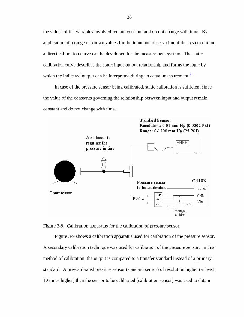
Figure 3-9. Calibration apparatus for the calibration of pressure sensor
Figure 3-9 shows a calibration apparatus used for calibration of the pressure sensor.
A secondary calibration technique was used for calibration of the pressure sensor. In this
method of calibration, the output is compared to a transfer standard instead of a primary
standard. A pre-calibrated pressure sensor (standard sensor) of resolution higher (at least
10 times higher) than the sensor to be calibrated (calibration sensor) was used to obtain

37
the calibration curve for the sensor being calibrated. The two sensors were
simultaneously subjected to a constant pressure. The pressure reading from the standard
sensor and the voltage reading from the calibration sensor were recorded. The output of
the calibration sensor was connected to the CR10 X. Since the voltage measured by the
CR10X is 2.5V maximum, a voltage divider circuit was used to reduce the voltage from
12V maximum to 2V maximum. To get a range of values of input pressure, an air bleed
valve was used to regulate the pressure and the readings were recorded for all the input
pressures. A calibration curve was obtained as shown in Figure 3-10. The voltage output
from the calibration sensor was a function of the input voltage to the sensor. When
logged through the CR10X data logger, it was observed that there were variations in the
input battery voltage to the data logger. Hence the output voltage was affected by these
variations. So the calibration curve was plotted in terms of input pressure verses voltage
ratio of Vin (recorded voltage in milli-volts) and battery voltage (VDC in volts).
Figure 3-10. Calibration curve for pressure sensor – Pressure vs. voltage ratio

38
The linear relationship between pressure and voltage ratio as obtained from the
calibration curve in Figure 3-10 is given by.
5885.2)()(*1231.0)(Pr −=
VVDCmVVinPSIessure
An instrument is sufficiently sensitive if the smallest input difference we want to
detect shows up as a measurable change in output of the sensor. The sensitivity of the
pressure sensor, given by the slope of the output vs. input plot was observed to be 0.1231.
The resolution of the pressure sensor was computed from the fact that the minimum
voltage change detected by the data acquisition was 1 mV, which gives a resolution of
0.01 PSI of pressure. This value was considered appropriate for the application under
consideration. In order to study the effect of hysteresis, during calibration the input
pressure to the sensor was varied in both directions from 0 to 15 PSI. It was observed
that the sensor was not affected by hysteresis, since it followed the same path in both
directions. As seen from the calibration curve, the sensor has good linearity as the output
varies linearly with the input over the complete range of the input values.
3.3.3.3 Connection to data acquisition system
For the modified SEBAC II prototype, operation was being monitored at regular
intervals. The pressure sensors were connected in the three pump lines. Figure 3-11
shows the circuit diagram for the connection of pressure sensor to the data acquisition
system through the voltage divider circuits.

39
Figure 3-11. Circuit diagram for connecting pressure sensors to data acquisition system
An acquisition time-interval of 600 seconds was chosen to record the data for the
data acquisition system. Arithmetic average of the last 10 values was used to calculate
the 10-number running average. This average of pressure data was conducted to smooth
out the instantaneous spikes. The program recorded the instantaneous pressure every 60
seconds and at the end of 600 seconds calculated the running average of the 10 readings
obtained during that period.
3.3.4 Automatic Actuation of Valves
As discussed previously, the optimum time for reversal of flow of leachate through
the reactors was between 4 to 6 hours. Hence, if the valves are programmed to actuate
automatically without human intervention, the crew time spent on the life support system
activities can be reduced.

40
Figure 3-12. Electrical wiring diagram for 115 VAC actuators
The three pairs of L-port three-way valves formed the part of the flow reversal
circuit as discussed earlier. These valves were fitted with actuators for automatic
actuation to obtain flow reversal whenever desired (Spears - E1454 005C). The actuators
were 115 VAC actuated and worked in pairs and were automatically energized using a
relay circuit controlled by the data acquisition system. The wiring diagram of the internal
circuit of the actuator is shown in Figure 3-12. Figure 3-13 shows the circuit diagram for
connection of the actuators with the CR10X. The control ports of CR10X controlled the
actuation of the relays which in turn activated the pair of actuators to reverse the flow.

41
Figure 3-13. Circuit diagram for connection of the pressure sensors to data acquisition
3.4 Process Control System
Some of the observations taken into consideration, while deciding on the control
strategy are summarized below:
• As described earlier, the volume of each reactor was 187 L while the flow rate of leachate was around 2 L per minute. Reversal of flow should occur only after the amount of flow in one direction was at least equal to the volumetric displacement

42
of reactor. It was found that the ideal time of reversal would be between 4 to 6 hours.
• Cumulative gas flow during an entire experimental run in each direction was computed from previous test run and it was observed that the amount of flow in up flow mode was 2039.5 N L in 16070 minutes and the amount of flow in down-flow mode was 2717.5 N L in 15500 minutes The overall gas flow rate in up flow was found to be less than down flow mode.
• It was observed that in up flow mode the rate of biogas production was low after initial burst of gas. The gas entrapped below the solids which start to form a lump against the top screen would escape because of the flow reversal. Hence an initial burst could be noticed. But once the gas had escaped, the rate of biogas generation was found to be lower.
So a control algorithm, based on time and pressure data was devised where-in the
down flow mode was allowed to operate for full 4 hours before switching. Where as
when in up flow mode, initial gas was allowed to escape and then feedback from pressure
data was used to control the flow. Figure 3-14 shows the flow chart for the control
system. The piping and instrumentation diagram for the modified SEBAC II prototype
system is shown in Figure 3-15.
The CR10X data acquisition and controller was used for implementing the control
algorithm. The pressure sensors, tipping gas meters and actuator functionality along with
the calibration procedure for sensors was described in earlier sections.
The source code for the algorithm for the CR10X panel has been provided in the
appendix C.22

43
Figure 3-14. Flow chart for control algorithm

44
Figure 3-15. Piping and instrumentation diagram for the modified SEBAC II prototype system

CHAPTER 4 RESULTS AND DISCUSSION
This chapter discusses the results obtained from the experiment runs performed on
the modified SEBAC II prototype. To compare the performance of the process control
system, the experiments were performed in three steps.
• Run 1 (Unidirectional flow) – An experimental run was conducted on the modified SEBAC II prototype without any flow reversal. The reactors were continuously operated in up flow mode with leachate entering the bottom of the reactor and leaving through the top. This experiment has been labeled “Unidirectional flow” in further discussion
• Run 2 (Periodic flow reversal) – This experimental run with automated operation was carried out on the modified SEBAC II prototype with periodic flow reversal at a fixed time interval of 4 hours. Pressure was only recorded during this experiment. This experiment has been labeled “Periodic flow reversal” in further discussion
• Run 3 (Adaptive control) – This experimental run was carried out with the implementation of the process control system with pressure feedback signal. This experiment has been labeled “Adaptive control” in further discussion
The three experiments were conducted with the same blend of feedstock consisting
of wheat straw, paper and dog food. The simulated feedstock used to load the new
reactor was in proportion with the expected waste produced during the long term space
mission. It included 5.5 kg of wheat straw, 3.63 kg of paper and 1.5 kg of dog food.
4.1 Feedstock Properties and Processing-BMP Analysis
Biochemical methane potential assay is used to determine the methane yield of an
organic material during its anaerobic decomposition by a mixed microbial flora in a
45

46
defined medium. The degradation of each sample was assumed to follow a first order
rate of decay with parameters Ym and k.
4.1.1 Determination of Ym, k
The parameters, Ym and k, were estimated using a nonlinear regression fit to the
yield data of a triplicate set. Sub-samples of the simulated feedstock for long term space
missions were dried and milled to the millimeter size. To determine the extent of
anaerobic biodegradation of feedstock, TS, VS and BMP assays were carried out on these
samples to find out the degradability of each type of feedstock.
A B C D
Figure 4-1. Components of the simulated feedstock for ALS mission (A) Paper (B) Wheat straw (C) Dog food (D) Leachate
Figure 4-2 shows the linear fit for methane produced at STP per kg of VS added for
the triplicate samples of dog food and wheat straw. The values of k for paper were
obtained from Owens et al.12 The values of TS, VS, k and Ym are listed in Table 4-1.
Table 4-1. TS, VS, k and Ym for components of simulated feedstock for ALS missions TS (%) VS (% TS) k (per day) CH4 Yield (N L / g VS) Paper 12 96.2 92.7 0.136 0.369 Dog food 92.4 94.8 0.109 0.547 Straw 88.87 97.47 0.061 0.209

47
Figure 4-2. Linear fit for BMP analysis of dog food and wheat straw
4.1.2 BMP for the Experimental Runs
For each of the three experimental runs, an estimate of 30 day methane yield for
mixture of paper, straw and dog food based on BMP results was computed. This yield
denoted the maximum methane yield that can be obtained from the feedstock. The
estimates for the three experimental runs are listed in table 4-2. The wet weight was the
weight of the feedstock put in the reactors at the start of the experimental run. The
amount of VS, which is the biodegradable mass, was calculated by knowing the total
weight, %TS and the %VS values. The total methane yield (L at STP) was computed
from the first order fit equation. A 30 day methane yield was assumed for these
calculations.
( )30*44 1**][][ ke
VSkgSTPatLyeildCHkgVSSTPatLCHTotal −−⎥
⎦
⎤⎢⎣
⎡=

48
Table 4-2. Methane yield estimate for the feedstock of 3 experimental runs Unidirectional flow Periodic reversal Adaptive control Paper Dog
food Straw Paper Dog
food Straw Paper Dog
food Straw
Wet weight added (kg)
3.68 0.75 5.47 3.63 1.50 5.44 3.63 1.50 5.44
VS (kg) 3.29 0.66 4.74 3.24 1.31 4.71 3.24 1.31 4.71 Total CH4 yield (N L)
1192.0 345.7 831.5 1173.7 691.4 827.2 1173.7 691.4 827.2
CH4 yield fraction (N L /kg VS total)
137.3 39.8 95.8 126.7 74.6 89.3 126.7 74.6 89.3
Total CH4 yield (N L/kg VS total)
272.90 290.64 290.64
4.2 Analysis of Process Control System
The chief objective of a process control system is to maintain a process at the
desired operating conditions, safely and efficiently. The major steps 21 involved in
designing and installing a process control system are to:
1. Formulate control objectives: The formulation is based on the operating objectives for the plant and the process constraints.
2. Develop process model: A dynamic model of the process should be developed after the control objectives have been formulated. The model can have a theoretical basis or it can be developed empirically from experimental data.
3. Devise control strategy: This step in the control system design is used to devise an appropriate control strategy that will meet the control objectives while satisfying the process constraints.
4. Select control hardware and software and install the control system: The components of a control system are generally divided in four general stages. The four stages form the bridge between input and the system output. The relationship between input information, as acquired by sensor, and system output is established by calibration. The four stages depicted in Figure 3-14 are defined as follows
a. Sensor transducer stage – A sensor uses some natural phenomenon to sense variable being measured. The transducer converts the sensed information into detectable signal form, which can be electrical, mechanical, optical, etc.
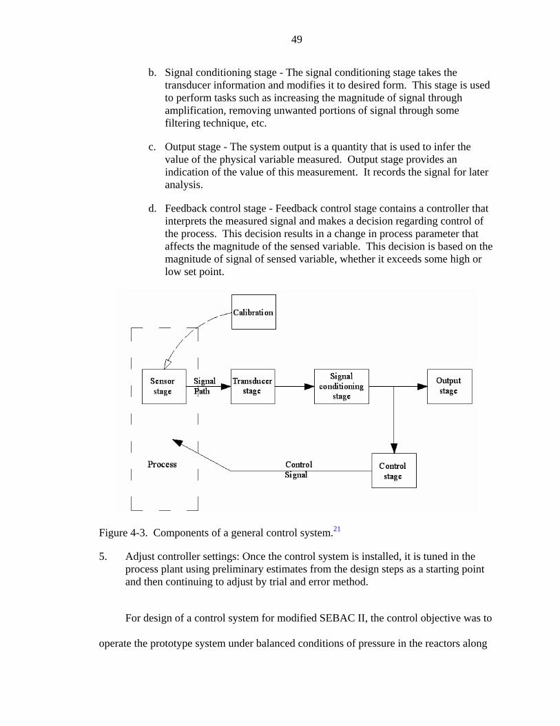
49
b. Signal conditioning stage - The signal conditioning stage takes the transducer information and modifies it to desired form. This stage is used to perform tasks such as increasing the magnitude of signal through amplification, removing unwanted portions of signal through some filtering technique, etc.
c. Output stage - The system output is a quantity that is used to infer the value of the physical variable measured. Output stage provides an indication of the value of this measurement. It records the signal for later analysis.
d. Feedback control stage - Feedback control stage contains a controller that interprets the measured signal and makes a decision regarding control of the process. This decision results in a change in process parameter that affects the magnitude of the sensed variable. This decision is based on the magnitude of signal of sensed variable, whether it exceeds some high or low set point.
Figure 4-3. Components of a general control system.21
5. Adjust controller settings: Once the control system is installed, it is tuned in the process plant using preliminary estimates from the design steps as a starting point and then continuing to adjust by trial and error method.
For design of a control system for modified SEBAC II, the control objective was to
operate the prototype system under balanced conditions of pressure in the reactors along

50
with increasing the efficiency of the system by increasing the rate of methane generation
from the system. The increase in pressure was an indication of build up of solids pressed
against the screen which caused clogging and hence high back pressures. One of the side
effects of this pressure build-up was the leakage from top or bottom of the reactors. The
formation of lumped mass also had the effect of decreased contact of leachate with the
solids hence decreasing the methane generation rate. Proper operation could be obtained
by maintaining the pressures below an upper threshold limit which would be obtained by
reversing the flow of leachate through the reactors.
To develop a model for the process and the control strategy for the controller, one
of the most important sources of information was the pilot plant data and previous data
from experiments. A lot of experimental data were available from the previous runs.
From these data an attempt was made to fit an empirical model for the process. It was
observed that the pressure steadily increased as there was continual flow in one direction.
It was further observed that when the flow of leachate through the reactors was reversed,
the solids would get loosened and move away from the screen causing a reduction in the
pressure and there would be a better mixing of solids with the leachate thus effecting a
potential increase in the reaction rate. Therefore a threshold based controller was chosen
for the application. For a threshold based controller, the process model was only required
to get an estimate of the value of the threshold. From the previous data of pressures in
the reactors, a pressure threshold value was chosen. The flow was reversed if this value
was reached. The pressures in the reactors were monitored and a feedback signal from
these pressure sensors was sent to the controller where it was compared with a threshold
value to make a decision as to switch flow or not.

51
4.2.1 Automatic Actuation of Valves
Equivalent system mass (ESM), the basis of the metric for measurement of
progress of the Advanced Life Support (ALS) project, is the mass of all entities,
including the structure required for pressurized volume, power system, and cooling
system, that are required to make a life support system function as intended, while
allowing the crew to pursue the experimental and exploratory goals of the mission. The
five components that form the ESM are: the actual system mass, the equivalent mass of
the volume occupied, the equivalent mass of the power requirement, the equivalent mass
of the cooling requirement, and the equivalent mass of the demands on crew time. The
components of ESM are defined in the following equations:
LSSCTCPVTOTAL tCPVMESM γγγγ ++++=
where,
⎥⎦
⎤⎢⎣
⎡−
=
==
=
wkpersonhspenttimeCrewt
kWtrequiremenCoolingCmVolumeV
kgMassM
LSS
][][
][3
⎥⎦⎤
⎢⎣⎡=
⎥⎦⎤
⎢⎣⎡=
kWkgfactorttureInfrastrucPower
mkgfactorttureInfrastrucVolume
P
V
cos
cos 3
γ
γ
⎥⎥⎥
⎦
⎤
⎢⎢⎢
⎣
⎡
⎟⎠⎞⎜
⎝⎛
−
=
⎥⎦⎤
⎢⎣⎡=
wkpersonh
kgfactorttimeCrew
kWkgfactorttureInfrastrucCooling
CT
C
cos
cos
γ
γ

52
It is assumed that the crew is on a mission for a reason that involves much of their
time. For example, they might be involved in extensive extravehicular activity (EVA) to
collect samples and to spend internal-vehicular activity (IVA) time analyzing those
samples. Thus, the crew’s working time is a limited resource, and any time that is spent
on life support operation and maintenance detracts from the primary purpose of the
mission.5
Based on practical operational experience with the SEBAC prototype, it was
assumed that the crew time for operating the HSLAD system was 10 min per day for
regular operation, 2 hours per month for inspection and maintenance, and 2 days per year
for parts replacement. So the crew time would be 0.417 hr / person-week. A detailed
ESM calculation was performed on the SEBAC system and was reported previously.17
Table 3-2 lists the components contributing to ESM for SEBAC process. The cost
factors were the nominal values cited from the baseline values and assumptions document
(BVAD) for the ALS mission.23
Table 4-3. Equivalent systems mass (ESM) for SEBAC system Parameter of HSLAD Cost factors for Mars surface ESM (kg)
Mass 181 kg 1 kg / kg 181
Volume 2 m3 2.08 kg / m3 4.16 Power 0.37 kW 86.9 kg / kW 32
Cooling 2.9kW 66.7 kg / kW 193 Crew Time 0.417 hr / person-wk 4923 kg / hr / person-wk 2053
Sum 2463
As seen from the table 3-2, the largest component contributing to the equivalent
systems mass is the crew time. The automatic actuation of valves was an attempt to
reduce the crew time which would decrease the value of ESM significantly.

53
4.2.2 Effect of Flow Reversal on Biogas Production
Figure 4-4 shows the plot of cumulative methane yield and methane generation rate
against time for a period of 3 days to demonstrate the effect of flow reversal on the
biogas generation through the process.
Figure 4-4. Effect of flow reversal on the biogas generation
The flow reversal through the reactors is shown with help of a step graph. When
the flow was in upward direction the step had a value of zero while downward flow had
value of one. It can be seen that whenever the flow was reversed, the gas entrapped
within the reactor was released, as evident from the step jump in the methane yield
expressed in CH4 N L/kg VS added as well as the spike in the methane production rate
plot which is expressed as CH4 N L/L/sample; liters of biogas produced at STP
conditions per liter of reactor volume per sampling time. The sampling rate in the data
acquisition system was 600 seconds.
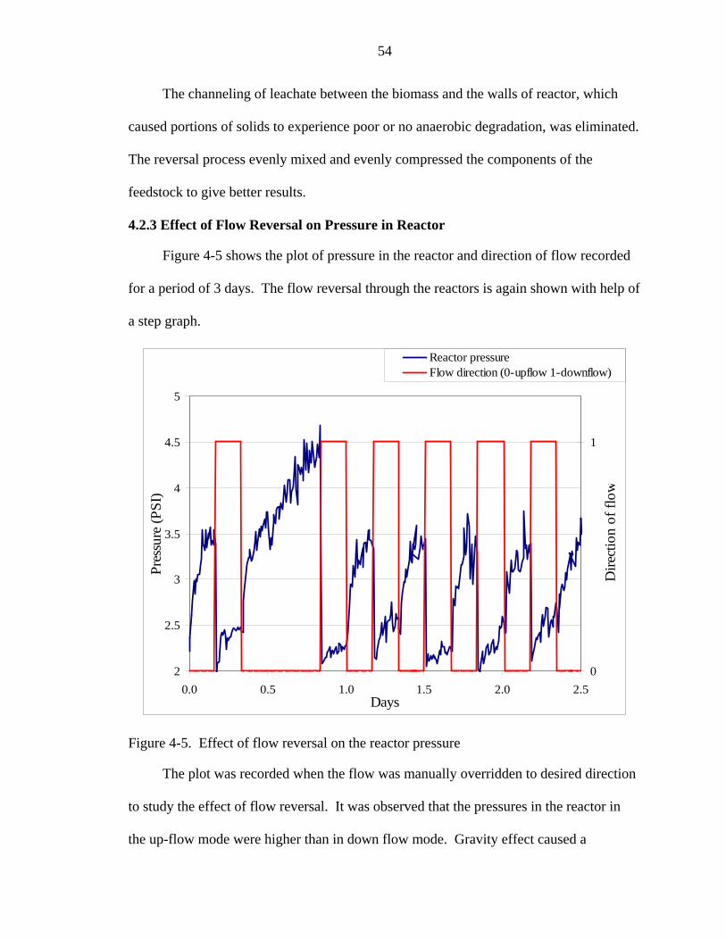
54
The channeling of leachate between the biomass and the walls of reactor, which
caused portions of solids to experience poor or no anaerobic degradation, was eliminated.
The reversal process evenly mixed and evenly compressed the components of the
feedstock to give better results.
4.2.3 Effect of Flow Reversal on Pressure in Reactor
Figure 4-5 shows the plot of pressure in the reactor and direction of flow recorded
for a period of 3 days. The flow reversal through the reactors is again shown with help of
a step graph.
2
2.5
3
3.5
4
4.5
5
0.0 0.5 1.0 1.5 2.0 2.5Days
Pres
sure
(PSI
)
0
1
Dire
ctio
n of
flow
Reactor pressureFlow direction (0-upflow 1-downflow)
Figure 4-5. Effect of flow reversal on the reactor pressure
The plot was recorded when the flow was manually overridden to desired direction
to study the effect of flow reversal. It was observed that the pressures in the reactor in
the up-flow mode were higher than in down flow mode. Gravity effect caused a

55
permanent dead band in operation in up-flow and down-flow mode. The dependence on
gravity will be nullified in microgravity environment, but from the test setup point of
view, it was difficult to simulate microgravity on the present setup.
Further it was observed that prolonged operation in up flow mode continuously
increased pressure. The pressures in down flow mode increased slowly as compared to
up flow mode where the rate of increase in pressure was prominent. The pressure signal
would be feedback to the control system and was compared to a threshold value to make
a decision for reversal of flow.
4.3 Performance of the System
In the daily operation of modified SEBAC II prototype system, pH of leachate from
the reactor and biogas production was recorded. The parameters used for comparison of
the performance of the three experimental runs were the methane generation rate and the
cumulative methane yield.
Figure 4-6, 4-7 and 4-8 show the performance of the three experimental runs.

56
Figure 4-6. Performance of modified SEBAC II system for experimental run with unidirectional flow (A) Cumulative methane yield and methane generation rate (B) pH of the leachate from the reactor over the period of the experiment

57
Figure 4-7. Performance of modified SEBAC II system for experimental run with periodic flow reversal (A) Cumulative methane yield and methane generation rate (B) pH of the leachate from the reactor over the period of the experiment

58
Figure 4-8. Performance of modified SEBAC II system for experimental run with adaptive control system (A) Cumulative methane yield and methane generation rate (B) pH of the leachate from the reactor over the period of the experiment
The biogas production was monitored over the course of duration of the
experimental run and cumulative methane produced from the feedstock was calculated

59
and expressed in the units of CH4 yield N L/ kg of VS added. It was observed that in run
with unidirectional flow, the cumulative yield reached 170 N L /kg VS at end of 62 days
while the theoretical value specified by BMP assay was 272.9 N L /kg VS. The yield of
run with periodic flow reversal was recorded to be 276.4 N L /kg VS in 22 days and the
yield of run with adaptive control system was 287.5 N L /kg VS at the end of day 14.
The theoretical value of maximum yield obtained from the BMP assay for both periodic
flow reversal and adaptive control system experiments was 290.64 N L /kg VS.
The rate of generation of biogas was another parameter used for comparison. It
was expressed in units of N L/L/day. It was observed that on a per reactor volume basis,
modified SEBAC-II with process control system consistently produced higher methane
generation rates during the experiments. The maximum methane generation rates
observed for the three experimental runs were 0.3 N L/L/day, 1.23 N L/L/day and 1.96 N
L/L/day respectively.
The pH of leachate was an indication of its acid content. It should be noted that all
three experimental runs operated at an approximate same pH value of approximately 7
with the last two experimental runs maintaining a slightly higher pH level.
The SEBAC process as envisioned for ALS missions would proceed through the
process of anaerobic digestion in a period of three weeks. Figure 4-9 shows the three
experimental runs compared over a period of three weeks. It was observed that the run
with unidirectional flow reached only up to 55 N L/kg VS. Unidirectional flow from
bottom of the reactor to the top caused formation of lumped mass of the solids pressed
against the top screen. Thus all the solids were not able to come in contact with the
leachate hence the digestion does not reach the value specified by the BMP assay. The

60
two runs with flow reversal system demonstrated faster reaction kinetics and reached to
near completion in three week period. It can be seen that the modified SEBAC-II with
process control system exhibited improved reaction kinetics as compared to modified
SEBAC-II with periodic flow reversal. The modified system with adaptive control
system (run 3) could digest the feedstock in a period of 14 days and would now be able to
support a new reactor for a new batch of feedstock during the third week into its
digestion.
Figure 4-9. Comparative performance for three runs on modified SEBAC II system
.

CHAPTER 5 CONCLUSIONS AND FUTURE WORK
The results presented in this research demonstrate that the modified SEBAC II
design showed positive results for decreased retention time of feedstock and balanced
operation. The automatic actuation of the valves through the use of actuators enabled the
flow reversal control system to act on the feedback pressure signal from the sensors.
With automated operation, an attempt was made towards decreasing the equivalent
systems mass (ESM) of the system, since one of the important parameter contributing to
the ESM is the crew time. The detailed systems analysis of the modified design has not
yet been performed but would be within the scope of future work.
This research reconfirmed the feasibility of the concept of SEBAC process for
completion of degradation of feedstock in a period of three weeks. From the results it was
seen that without the modifications, the system will not adequately perform without the
flow reversal system. The periodic flow reversal enabled the feedstock to degrade
completely but the concern was the fact that the retention time was more than anticipated.
The implementation of process control showed that the retention time was reduced by
one-third and degradation could be completed in the given time frame of two weeks
before the reactor could perform the role of a mature reactor for helping to start a new
reactor.
The results reveal that balanced operation in terms of pressure in reactor can be
obtained by reversing the flow of leachate through the reactors. In an indirect
implication, reduced maximum pressure of the system reduces the ESM, since one of the
61

62
factors contributing to the ESM is the pressurized volume of the system. Smaller
maximum pressure values will decrease the ESM.
The results also show that at the data acquisition and monitoring system which
enabled real-time data recording and analysis, provided a better understanding of the
process and further changes in the process parameters can also be studied.
5.1 Recommendations
The process control algorithm suggested in this research to control the flow through
the reactors is to demonstrate the increase in reaction kinetics by effecting maximum
contact of leachate with the feedstock. It takes into account the effect of gravity while
taking the decision for flow reversal. In microgravity, the pressures up-flow and down-
flow would be same and in that environment the pressure algorithm will have to be
implemented both in up-flow and down-flow mode. The pressure threshold values will
also have to be set by first performing some trial runs in the microgravity environment.
5.2 Suggestions for Future Work
This work was a step to demonstrate the data monitoring and automation capability
of the SEBAC II process and can be further improved. These studies here open some
areas for expansion of this research. The following topics of interest can be addressed:
• Further research on studying the effect of temperature and the flow rate on the process behavior and plotting similar performance graphs would be helpful to increase the reaction kinetics and optimize the performance of the control system. Temperature sensors like thermocouple can be easily integrated with the CR10X data logger and can be helpful in controlling the performance of the system by optimizing the heat supplied. Also the motor speed controllers can be used to control the amount of leachate delivered to the reactor.
• The crew time spent on the SWM component of the life support system can be further decreased by the automation of loading and unloading operation of the reactor. Presently, the reactors are being envisioned as being filled with one week’s feed by loading it directly in to the reactor and compacting it. Initial research has shown that automatic operation of SEBAC in loading –unloading

63
operation is possible through the use of baskets. The effort can be significantly reduced if three baskets concentric with the reactor would be used to fill the feedstock. One basket collecting two days worth of the feedstock. These baskets would then be compacted to the requisite bulk density and then pushed into the reactors with help of a material handling system.

APPENDIX A OPERATION MANUAL FOR MODIFIED SEBAC II
Modified SEBAC II prototype composed of 5 reactors, 2 reservoirs, 3 pumps and
more than 50 valves is a complex assembly to understand for a novice. This operation
manual aims to help an operator to choose the right operating conditions so that prototype
operation is proper.
Notation of components of the system
Figure A-1 shows the piping and instrumentation diagram of the modified SEBAC
II system. Notations used to denote each component are also shown in the figure. P1, P2
and P3 are the three pumps used to pump leachate in the three reactors forming the three
stages of anaerobic digestion. Pump P1 should be used to pump into the reactor in new
stage, pump P2 should be used to pump into the reactor in mature stage and pump P3
should be used to pump into the reactor in activated stage.
The five reactors are labeled R1 – R5. During a particular run, the five reactors
assume one of the following roles:
• Reactor used for collection • Reactor in new stage • Reactor in activated stage • Reactor in mature stage • Reactor for post-processing and stabilization
Reservoir Rs1 supplies leachate to reactors in new stage and mature stage, while
the other reservoir Rs2 supplies leachate to the reactor in activated stage. Valves 11 to
56, are 30 two-way valves (six per reactor) to connect the six pump manifold lines with
64

65
each reactor. G1 toG5 are the gas exhaust valves at the top of each reactor and RG1 and
RG2 are the exhaust valves at the top of reservoirs. They are used to allow the gas to
escape to the gas meters. TV1 is used when the leachate in one reactor is to be directly
transferred to the other reactor. It will divert the flow from pump manifold line 2 to the
inlet of the pump and shut-off the reservoir from the circuit. The flow to the pumps P2
and P3 from the two reservoirs can be plugged by operating valves RV1 and RV2.
Figure A-1. Notation used to denote various components of modified SEBAC II
Operation sequence
Though not limited to the following combinations, it is advised that the reactors be
operated in one of the following sequences.

66
Table A-1. Operation sequence for SEBAC Reactor Seq No. (Operation )
R1 R2 R3 R4 R5
O-1 Mature Activated New Collection Post-processing
O-2 Post-processing Mature Activated New Collection
O-3 collection Post-processing Mature Activated New
O-4 New Collection Post-processing Mature Activated
O-5 Activated New Collection Post-processing Mature
At the outlet of the pumps, there is a flow reversal circuit formed by 3 pairs of
three-way valves with actuators fitted on the top of each valve. These valves are used to
reverse the flow of leachate through the reactors. For example, O-1 U will represent the
operation sequence 1 (of table 1) in upward flow through the reactor (bottom to top) and
O-1 D will represent the operation sequence 1 (of table 1) in downward flow (top to
bottom).
It is imperative that the right valves be opened and other valves be kept closed for
proper flow of leachate, because if not directed properly, the flow of leachate can occur
to an undesirable place. Table A-2 below gives a summary of the valves to be opened for
above mentioned 6 operating sequences in both up-flow and down-flow modes of
operation.
Table A-2. Valve positions for different operating sequences
Mature: Pump P1 Open valves
New: Pump P2 Open valves
Activated: Pump P3 Open valves
Input output Input output Input output O-1 U V13 V16 V32 V35 V21 V24 O-2 U V23 V26 V42 V45 V31 V34

67
O-3 U V33 V36 V52 V55 V41 V44 O-4 U V43 V46 V12 V15 V51 V54 O-5 U V53 V56 V22 V25 V11 V14 O-1 D V16 V13 V35 V32 V24 V21 O-2 D V26 V43 V45 V42 V34 V31 O-3 D V36 V43 V55 V52 V44 V41 O-4 D V46 V53 V15 V12 V54 V51 O-5 D V56 V53 V25 V22 V14 V11
Starting a new experiment run
Some important aspects while starting an experiment run are discussed below
Feedstock preparation
Rice or wheat straw (obtained whole) should be shredded to a particle size of 2 – 5
cm using a yard chipper/shredder (Yard Machines MTD 5.5 HP). Repeated shredding
may be required to be done so as to get the appropriate particle size. Paper should be
shredded using a crosscut paper shredder to a particle size of 1-2 cm (Fellows model
PS8OC-2). Dog food should be placed into the reactor as an unaltered pellet with an
average maximum dimension of 1.3 cm (Science Diet Large Canine Growth formulated
by Hill’s Pet Nutrition, Inc.)
Transfer of leachate from one reactor to another
As defined in the SEBAC operation, the new reactor contains the fresh feedstock
which is helped by the mature reactor so that after one week it can sustain itself. Once
the feedstock has passed through the mature stage, it can be used as a substrate for
revitalization system. At this stage all the leachate contained in the reactor has to be
removed. At the same time there is a new reactor, the feedstock from which needs to be
wetted with leachate. Hence, the operation can be streamlined by directly transferring the
leachate from one reactor to another. The steps to be taken while transferring the
leachate from one reactor to another are given below:

68
• Turn-off the reservoir Rs1 by shutting off valve RV1
• Turn the three way valve TV1 to connect pump manifold line 2 to inlet of pump 1
• Consider the reactor from which leachate is to be drawn, open the valve connecting the reactor and the pump manifold line 2 ( V12, V22, V32, V42 or V52 depending on which reactor is in mature stage)
• Open the gas exhaust valve for the reactor from which leachate is drawn to prevent creation of vacuum (G1, G2, G3, G4 or G5 depending on which reactor is in mature stage)
• Consider the reactor into which the leachate is to be pumped in, open the valve connecting the reactor and the pump manifold line 6 ( V16, V26, V36, V46 or V56 depending on which reactor is being started)
• Pump 1 is to be used for this pumping operation, load the following program in the CR10X controller to operate the pump 1 and the direction control valves in down-flow mode.
• Start the pump and run it until all the leachate is drawn
--------------------------------------------------------------------
;{CR10X} ; PROGRAM TO OPERATE SET 1 IN DOWNFLOW MODE ; USED WHEN TRANFERRING LEACHATE FROM ONE REACTO TO ANOTHER *Table 1 Program 01: 60 Execution Interval (seconds) 1: Do (P86) 1: 41 Set Port 1 High 2: Do (P86) 1: 10 Set Output Flag High (Flag 0) *Table 2 Program 02: 0.0000 Execution Interval (seconds) *Table 3 Subroutines End Program --------------------------------------------------------------------
Gas lines
The circuit for the gas lines is used to direct the gas from the reactors to the tipping
bucket gas meters. Care should be taken to make the correct gas line connections. Two

69
gas meters are used to measure the gas generated in the activated reactors and combined
mature and new reactors. The appropriate valves out of G1, G2, G3, G4 and G5 should
be chosen. The quick disconnect couplings are used to connect the appropriate lines to
the three lines coming from the gas meters. Please refer to Figure 3-4 for details of the
circuits. There is a provision for accumulation of the gas which can be used as a fuel to
burn. The gas meters should be sealed with silica glue and the exhaust of the gas meter
should be connected to the inverted gas tank inlet to accumulate the gas.
Connections for data acquisition system
The CR10X data logger works on a 12 VDC power supply which is provided by an
external battery. The wiring panel, on the top, provides terminals for connecting sensors,
control and power leads to the CR10X. The wiring diagram for the data acquisition
system is shown in figure A-2.
The CR10X has a 128K flash electrically erasable programmable read only
memory (EEPROM) and static random access memory (SRAM). The flash EEPROM is
used to store the operating system and user programs while RAM is used for data and
running the programs.
The data-logger communicates with the PC via serial communication port. The 9
pin serial I/O port contains lines for serial communication between CR10X and external
devices (PC, keyboard etc.). An SC32B optically isolated interface is required for direct
communication between the CR10X data-logger and the serial port of a computer. The
SC32B is used to isolate the computer's electrical system from the data-logger, thereby
protecting against ground loop, normal static discharge, and noise. It also converts the
computer's RS-232 voltage levels to the CMOS levels used by the data-logger.

70
Figure A-2. Wiring diagram for connection to the data acquisition
The data-logger does not have inbuilt programming capabilities. LoggerNet
software is used to support programming, communications, and data retrieval between

71
the data-logger and a PC. The loggerNet toolbar consists of applications to create data-
logger programs (Short cut, Edlog) or process data (Split), or graph / display data (View,
RTMC) and communicate with the data-loggers (Connect, Ezsetup). Edlog programming
utility is used to program the code for modified SEBAC II prototype. Once you have
written the source code for the program, compile it to check for errors. Connect utility
should be used to download the program into the data-logger and to retrieve the saved
data. The download file (*.DLD) obtained after compiling the program, should be
downloaded to the data-logger. Make sure that the time synchronization between the
station and the PC is performed so that the time-stamp recorded by the data logger is
correct. It can be done by setting the station clock through connect utility. Use the
collect feature of the utility to retrieve the data from the data logger. Post processing of
data can be done with the help of VIEW utility which lets you plot the data and analyze
it.

APPENDIX B SOURCE CODE FOR PROCESS CONTROL ALGORITHM
;{CR10X} ; COMPLETE PROGRAM ; PROGRAMMER : SUNEET LUNIYA ; SEBAC RUN : MAY 11, 2005 ; MATURE REACTOR : R2 (Set 1) ; ACTIVATED REACTOR : R5 (Set 2) ; NEW REACTOR : R4 (Set 3) ; COMMENTS: PRESSURE : RUNNING AVERAGE RECORDED, CONTROL BASED ON PRESSURE DATA ; GASMETER : MONITORING ONLY ; ACTUATORS : ALGORITHM BASED ON PRESSURE FEEDBACK ; TEMPERATURE: AMBIENT TEMPERATURE MEASURED ; VERSION: MAY 11, 2005 FEEDBACK CONTROL ALGORITHM INCLUDED FOR THE NEW RUN ; FLAG / PORT USAGE: ; ; PORT 1: USED TO CONTROL ACTUATOR SET 1 ; LOW - ACTUATOR AND VALVE SET 1 IN UPFLOW MODE ; HIGH- ACTUATOR AND VALVE SET 1 IN DOWNFLOW MODE ; ; PORT 2: USED TO CONTROL ACTUATOR SET 2 ; LOW - ACTUATOR AND VALVE SET 2 IN UPFLOW MODE ; HIGH- ACTUATOR AND VALVE SET 2 IN DOWNFLOW MODE ; ; PORT 3: USED TO CONTROL ACTUATOR SET 1 ; LOW - ACTUATOR AND VALVE SET 3 IN UPFLOW MODE ; HIGH- ACTUATOR AND VALVE SET 3 IN DOWNFLOW MODE ; ; FLAG 1: USED FOR OUTPUT STORAGE ROUTINE ; LOW - NO ACTION ; HIGH- OUTPUT STORAGE ROUTINE ; ; FLAG 2: MAPS THE STATUS OF THE PORT 1 ; LOW - FOR DENOTING SET 1 IN UPFLOW MODE ; HIGH- FOR DENOTING SET 1 IN DOWNFLOW MODE ; ; FLAG 3: MAPS THE STATUS OF THE PORT 2 ; LOW - FOR DENOTING SET 2 IN UPFLOW MODE ; HIGH- FOR DENOTING SET 2 IN DOWNFLOW MODE ; ; FLAG 4: MAPS THE STATUS OF THE PORT 3 ; LOW - FOR DENOTING SET 3 IN UPFLOW MODE ; HIGH- FOR DENOTING SET 3 IN DOWNFLOW MODE ;
72

73
; FLAG 5: RESETED EVERY 10 MINUTES TO CALCULATE RUNNING AVERAGE ; LOW - FOR DENOTING START OF NEW INTERVAL ; HIGH- FOR DENOTING CONTINUATION OF CALCULATION OF RUNNING AVERAGE ; THRESHOLD CODES ; ; Plast: THRESHOLD VALUE 4.0 PSI PRESSURE ; SUBROUTINES: ; SUBROUTINE 1: INITIALIZE PROGRAM VARIABLES AND CAPTURE PORT STATUS IN FLAGS ; SUBROUTINE 2: SWITCH DIRECTION OF FLOW FOR ACTIVATED REACTOR ; SUBROUTINE 3: SWITCH DIRECTION OF FLOW FOR NEW AND MATURE REACTORS ; SUBROUTINE 4: INCREMENT FLOW REVERSAL COUNTER FOR NEW AND MATURE REACTORS ; SUBROUTINE 5: INCREMENT FLOW REVERSAL COUNTER FOR ACTIVATED REACTOR ;====================================================================== *Table 1 Program 01: 60 Execution Interval (seconds) ;----------------------=======================------------------------- ; PROGRAM SIGNATURE - ALLOWS USER TO DETECT PROGRAM CHANGES OR ROM FAILURE 1: If time is (P92) 1: 0 Minutes (Seconds --) into a 2: 1440 Interval (same units as above) 3: 30 Then Do 2: Signature (P19) 1: 18 Loc [ Prog_Sig ] 3: End (P95) ;----------------------=======================------------------------- ; READ BATTERY VOLTAGE 4: Batt Voltage (P10) 1: 14 Loc [ BattVolt ] ;----------------------=======================------------------------- ; CALL SUBROUTINE 3 TO INITIALIZE VARIABLES AND FLAGS 5: Do (P86) 1: 1 Call Subroutine 1 ;----------------------=======================------------------------- ; SENSOR MEASUREMENTS ; COUNT GAS METER 1 CLICKS: COMBINED NEW AND MATURE REACTORS

74
6: Pulse (P3) 1: 1 Reps 2: 1 Pulse Channel 1 3: 2 Switch Closure, All Counts 4: 1 Loc [ Cnt_New ] 5: 1.0 Mult 6: 0.0 Offset ; COUNT GAS METER 2 CLICKS: ACTIVATED REACTOR 7: Pulse (P3) 1: 1 Reps 2: 2 Pulse Channel 2 3: 2 Switch Closure, All Counts 4: 2 Loc [ Cnt_Act ] 5: 1.0 Mult 6: 0.0 Offset ; PRESSURE SENSOR READING - DIFFERENTIAL VOLTAGE MEASUREMENT ; SET 1 RED WIRES - MATURE REACTOR 8: Volt (Diff) (P2) 1: 1 Reps 2: 05 2500 mV Slow Range 3: 1 DIFF Channel 4: 5 Loc [ Volt1 ] 5: 1 Mult 6: 0.0 Offset ; SET 2 GREEN WIRES - NEW REACTOR 9: Volt (Diff) (P2) 1: 1 Reps 2: 05 2500 mV Slow Range 3: 2 DIFF Channel 4: 6 Loc [ Volt2 ] 5: 1 Mult 6: 0.0 Offset ; SET 3 BLUE WIRES - ACTIVATED REACTOR 10: Volt (Diff) (P2) 1: 1 Reps 2: 05 2500 mV Slow Range 3: 3 DIFF Channel 4: 7 Loc [ Volt3 ] 5: 1 Mult 6: 0.0 Offset ; THERMOCOUPLE - AMBIENT TEMPERATURE MEASUREMENT 11: Internal Temperature (P17) 1: 9 Loc [ Ref_Temp ] 12: Thermocouple Temp (DIFF) (P14)

75
1: 1 Reps 2: 1 2.5 mV Slow Range 3: 5 DIFF Channel 4: 1 Type T (Copper-Constantan) 5: 9 Ref Temp (Deg. C) Loc [ Ref_Temp ] 6: 10 Loc [ Amb_Temp ] 7: 1.0 Mult 8: 0.0 Offset ;----------------------=======================------------------------- ; CALCULATE CUMULATIVE GASMETER READINGS Tot_New = Tot_New + Cnt_New Tot_Act = Tot_Act + Cnt_Act ; CALCULATE PRESSURE (PSI) FROM CALIBRATION CURVE AND VOLTAGE MEASUREMENT Press1 = (Volt1 / BattVolt) * Slope - Bias Press2 = (Volt2 / BattVolt) * Slope - Bias Press3 = (Volt3 / BattVolt) * Slope - Bias ;----------------------=======================------------------------- ; CHECK FOR PRESSURE IN THE NEW REACTOR - THIS REACTOR HAS MORE ; PRESSURE VARIATIONS AS COMPARED TO MATURE REACTOR ; IF UP FLOW MODE OF OPERATION, APPLY PRESSURE BASED FEEDBACK CONTROL ; TIMER FOR COMPUTING TIME SINCE LAST FLOW REVERSAL 13: Timer (P26) 1: 23 Loc [ Tsec ] ; CONVERSION TO MINUTES Tmin = Tsec / 60 ; CHECK FOR DOWNFLOW 14: If Flag/Port (P91) 1: 12 Do if Flag 2 is High 2: 30 Then Do 15: If (X<=>F) (P89) 1: 25 X Loc [ Tmin ] 2: 3 >= 3: 240 F 4: 30 Then Do 16: Do (P86) 1: 3 Call Subroutine 3

76
17: Do (P86) 1: 4 Call Subroutine 4 18: Timer (P26) 1: 0 Reset Timer 19: End (P95) 20: End (P95) ; CHECK FOR UPFLOW 21: If Flag/Port (P91) 1: 22 Do if Flag 2 is Low 2: 30 Then Do 22: If (X<=>F) (P89) 1: 25 X Loc [ Tmin ] 2: 3 >= 3: 120 F 4: 30 Then Do 23: If Flag/Port (P91) 1: 25 Do if Flag 5 is Low 2: 30 Then Do Tlast = Tmin 24: Do (P86) 1: 15 Set Flag 5 High 25: End (P95) 26: Z=X+Y (P33) 1: 21 X Loc [ AvgP ] 2: 15 Y Loc [ Press1 ] 3: 21 Z Loc [ AvgP ] 27: Z=Z+1 (P32) 1: 24 Z Loc [ Pulses ] Diff = Tmin - Tlast 28: If (X<=>F) (P89) 1: 26 X Loc [ Diff ] 2: 3 >= 3: 10 F 4: 30 Then Do 29: Z=X/Y (P38) 1: 21 X Loc [ AvgP ] 2: 24 Y Loc [ Pulses ] 3: 22 Z Loc [ Plast ] 30: Z=F x 10^n (P30)

77
1: 0 F 2: 0 n, Exponent of 10 3: 21 Z Loc [ AvgP ] 31: Z=F x 10^n (P30) 1: 0 F 2: 0 n, Exponent of 10 3: 24 Z Loc [ Pulses ] 32: Do (P86) 1: 25 Set Flag 5 Low 33: If (X<=>F) (P89) 1: 22 X Loc [ Plast ] 2: 3 >= 3: 4.0 F 4: 30 Then Do 34: Do (P86) 1: 3 Call Subroutine 3 35: Do (P86) 1: 4 Call Subroutine 4 36: Timer (P26) 1: 0000 Reset Timer 37: End (P95) 38: End (P95) 39: If (X<=>F) (P89) 1: 25 X Loc [ Tmin ] 2: 3 >= 3: 240 F 4: 30 Then Do 40: Do (P86) 1: 3 Call Subroutine 3 41: Do (P86) 1: 4 Call Subroutine 4 42: Timer (P26) 1: 0000 Reset Timer 43: End (P95) 44: End (P95) 45: End (P95) ;----------------------=======================------------------------- ; SWITCH ACTIVATED REACTOR EVERY 4 HOURS

78
46: If time is (P92) 1: 0 Minutes (Seconds --) into a 2: 240 Interval (same units as above) 3: 30 Then Do 47: Do (P86) 1: 2 Call Subroutine 2 48: Do (P86) 1: 5 Call Subroutine 5 49: End (P95) ;----------------------=======================------------------------- ; OUTPUT STORAGE ROUTINE 50: If time is (P92) 1: 0 Minutes (Seconds --) into a 2: 10 Interval (same units as above) 3: 10 Set Output Flag High (Flag 0) 51: Set Active Storage Area (P80)^24088 1: 1 Final Storage Area 1 2: 101 Array ID 52: Real Time (P77)^27072 1: 1221 Year,Day,Hour/Minute,Seconds (midnight = 2400) 53: Sample (P70)^3244 1: 1 Reps 2: 18 Loc [ Prog_Sig ] 54: Resolution (P78) 1: 1 High Resolution 55: Sample (P70)^6106 1: 1 Reps 2: 3 Loc [ Tot_New ] 56: Sample (P70)^7517 1: 1 Reps 2: 4 Loc [ Tot_Act ] 57: Resolution (P78) 1: 0 Low Resolution 58: Average (P71)^3205 1: 1 Reps 2: 15 Loc [ Press1 ] 59: Average (P71)^2918 1: 1 Reps 2: 16 Loc [ Press2 ] 60: Average (P71)^4114 1: 1 Reps

79
2: 17 Loc [ Press3 ] 61: Sample (P70)^17516 1: 1 Reps 2: 8 Loc [ Switch ] 62: Sample (P70)^30155 1: 1 Reps 2: 11 Loc [ DownFlw1 ] 63: Sample (P70)^7134 1: 1 Reps 2: 12 Loc [ DownFlw2 ] 64: Sample (P70)^23161 1: 1 Reps 2: 13 Loc [ DownFlw3 ] 65: Sample (P70)^27789 1: 1 Reps 2: 22 Loc [ Plast ] 66: Average (P71)^2507 1: 1 Reps 2: 14 Loc [ BattVolt ] 67: Average (P71)^11170 1: 1 Reps 2: 10 Loc [ Amb_Temp ] ;----------------------=======================------------------------- *Table 2 Program 02: 0.0000 Execution Interval (seconds) ;----------------------=======================------------------------- *Table 3 Subroutines ;----------------------=======================------------------------- ; SUBROUTINE 1: INITIALIZE PROGRAM VARIABLES AND CAPTURE PORT STATUS 1: Beginning of Subroutine (P85) 1: 1 Subroutine 1 2: Z=F x 10^n (P30) 1: 0.1231 F 2: 00 n, Exponent of 10 3: 19 Z Loc [ Slope ] 3: Z=F x 10^n (P30) 1: 2.5885 F 2: 00 n, Exponent of 10 3: 20 Z Loc [ Bias ] ; SET VALUES OF FLAGS

80
4: If Flag/Port (P91) 1: 41 Do if Port 1 is High 2: 30 Then Do 5: Do (P86) 1: 12 Set Flag 2 High 6: Else (P94) 7: Do (P86) 1: 22 Set Flag 2 Low 8: End (P95) 9: If Flag/Port (P91) 1: 42 Do if Port 2 is High 2: 30 Then Do 10: Do (P86) 1: 13 Set Flag 3 High 11: Else (P94) 12: Do (P86) 1: 23 Set Flag 3 Low 13: End (P95) 14: If Flag/Port (P91) 1: 43 Do if Port 3 is High 2: 30 Then Do 15: Do (P86) 1: 14 Set Flag 4 High 16: Else (P94) 17: Do (P86) 1: 24 Set Flag 4 Low 18: End (P95) 19: End (P95) ;----------------------=======================------------------------- ; SUBROUTINE 2: SWITCH ACTIVATED REACTORS 20: Beginning of Subroutine (P85) 1: 2 Subroutine 2 21: Do (P86) 1: 63 Toggle Port 3 22: End (P95)

81
;----------------------=======================------------------------- ; SUBROUTINE 3: SWITCH NEW AND ACTUATED REACTORS 23: Beginning of Subroutine (P85) 1: 3 Subroutine 3 24: Do (P86) 1: 61 Toggle Port 1 25: Do (P86) 1: 62 Toggle Port 2 26: End (P95) ;----------------------=======================------------------------- ; SUBROUTINE 4: INCREMENT FLOW REVERSAL COUNTER FOR NEW AND MATURE REACTORS 27: Beginning of Subroutine (P85) 1: 4 Subroutine 4 Switch = Switch + 1 ; FLAG HIGH IS ANALOGOUS TO DOWNWARD FLOW 28: If Flag/Port (P91) 1: 41 Do if Port 1 is High 2: 30 Then Do DownFlw1 = 1 29: Else (P94) DownFlw1 = 0 30: End (P95) 31: If Flag/Port (P91) 1: 42 Do if Port 2 is High 2: 30 Then Do DownFlw2 = 1 32: Else (P94) DownFlw2 = 0 33: End (P95) 34: End (P95) ;----------------------=======================------------------------- ; SUBROUTINE 5: INCREMENT FLOW REVERSAL COUNTER FOR ACTIVATED REACTOR

82
35: Beginning of Subroutine (P85) 1: 5 Subroutine 5 36: If Flag/Port (P91) 1: 14 Do if Flag 4 is High 2: 30 Then Do DownFLw3 = 1 37: Else (P94) DownFLw3 = 0 38: End (P95) 39: End (P95) ;----------------------=======================------------------------- End Program

83
-Input Locations- 1 Cnt_New 1 0 1 2 Cnt_Act 1 0 1 3 Tot_New 1 1 0 4 Tot_Act 1 1 0 5 Volt1 1 0 1 6 Volt2 1 0 1 7 Volt3 1 0 1 8 Switch 1 1 0 9 Ref_Temp 1 1 1 10 Amb_Temp 1 1 1 11 DownFlw1 1 1 0 12 DownFlw2 1 1 0 13 DownFlw3 1 1 0 14 BattVolt 1 1 1 15 Press1 1 2 0 16 Press2 1 1 0 17 Press3 1 1 0 18 Prog_Sig 1 1 1 19 Slope 1 0 1 20 Bias 1 0 1 21 AvgP 1 2 2 22 Plast 1 2 1 23 Tsec 1 0 1 24 Pulses 1 1 2 25 Tmin 1 3 0 26 Diff 1 1 0 27 CSI_R 0 0 0 28 CSI_1 0 0 0 29 Tlast 0 0 0 -Program Security- 0000 0000 0000 -Mode 4- -Final Storage Area 2- 0 -CR10X ID- 0 -CR10X Power Up- 3 -CR10X Compile Setting- 3 -CR10X RS-232 Setting- -1 -DLD File Labels- 0 -Final Storage Labels- 0,Year_RTM,27072 0,Day_RTM 0,Hour_Minute_RTM 0,Seconds_RTM 1,Switch~8,17516 2,DownFlw1~11,30155 3,DownFlw2~12,7134 4,DownFlw3~13,23161 5,101,24088

84
6,Press2_AVG~16,2918 7,Press3_AVG~17,4114 8,BattVolt_AVG~14,2507 9,Press1_AVG~15,3205 10,Prog_Sig~18,3244 11,Plast~22,27789 12,Tot_New~3,6106 13,Tot_Act~4,7517 14,Amb_Temp_AVG~10,11170

LIST OF REFERENCES
1. Verostko, C., Joshi, J., Alazraki, M., Fisher, J., Solids Waste Processing and Resource Recovery-A Workshop Report-Volume II, Document No. CTSD-ADV-474, NASA, Lyndon B. Johnson Space Center, Houston, Texas, March 2001
2. Chynoweth, D., Legrand, R., Apparatus and Method for Sequential Batch Anaerobic Composting of High Solids Organic Feedstock, U.S. Patent 5269634, 1993
3. Chynoweth, D., Bosch, G., Earle, J., Legrand, R., Liu, K., A Novel Process for Anaerobic Composting of Municipal Solid Waste, Applied Biochemistry and Biotechnology, Vol. 28/29, 421-432, Spring 1991
4. O'Keefe, D., Chynoweth, D., Barkdoll, A., Nordstedt, R., Owens, J., Sifontes, J., Sequential Batch Anaerobic Composting, Water Science Technology, Vol. 27, 77-86, 1993
5. Levri, J., Drysdale, A., Ewert, M., Fisher, J., Hanford, A., Hogan, J., Jones, H., Joshi, J., Vaccari, D., Advanced Life Support Equivalent System Mass Guidelines Document, Document No. NASA/TM—2003-212278, NASA, Ames Research Center, Moffett Field, California, September 2003
6. Hanford, A., A List of Life Support Subsystems for the Advanced Life Support Project, Document No. MSAD-00-0138, Lockheed Martin Space Operations, Houston, Texas, 2000
7. Verostko, C., Packham, N., Henninger, D., Final Report on NASA Workshop on Resource Recovery from Wastes Generated in Lunar/Mars Controlled Ecological Life Support Systems (CELSS), Document No. CTSD-ADV-035, NASA, Lyndon B. Johnson Space Center, Houston, Texas, August 1992
8. Hoffman, S., Kaplan, D., Human Exploration of Mars: The Reference Mission of the NASA Mars Exploration Study Team, Document No. NASA-SP-6107, NASA, Lyndon B. Johnson Space Center, Houston, Texas, 1997
9. Kang, S., Hogan, J., Optimization of Feedstock Composition and Pre-Processing for Composting in Advanced Life Support Systems, Paper No. 2001-01-2297, 31st International Conference on Environmental Systems (ICES 2001), Orlando, Florida, July 2001
85

86
10. Teixeira, A., Chynoweth, D., Haley, P., Sifontes J., Commercialization of SEBAC Solid Waste Management Technology, Paper No. 2003-01-2341, 33rd International Conference on Environmental Systems (ICES 2003), Vancouver, Canada, July 2003
11. International Energy Agency, Systems and Markets Overview of Anaerobic Digestion, Publication of IEA Bio-energy, Anaerobic Digestion Activity, Paris, France, 1997
12. Owens, J., Chynoweth, D., Turick, C., Jerger, D., Peck, M., Biochemical Methane Potential of Biomass and Waste Feed stocks, Biomass and Bioenergy, Vol. 5(1), 95-11, 1993
13. Owen, W., Stuckey, D., Healy, J. B. Jr., Young, L., McCarty, P., Bioassay for Monitoring Biochemical Methane Potential and Anaerobic Toxicity, Water Research, Vol. 13, 485-492, 1979
14. Chynoweth, D., Haley, P., Owens, J., Rich, E., Townsend, T., Choi, H., Anaerobic Composting for Recovery of Nutrients, Compost, and Energy from Solid Wastes during Space Missions, Paper No. 2002-01-2351, 32nd International Conference on Environmental Systems (ICES 2002), San Antonio, Texas, July 2002
15. Engeli, H., Edelmann, W., Fuchs, J., Rottermann, K., Survival of Plant Pathogens and Weeds during Anaerobic Digestion, Water Science Technology, Vol. 27, 69-76, 1993
16. Bendixen, H., Safeguards against Pathogens in Danish Biogas Plants, Water Science Technology, Vol. 30, 171-180, 1994
17. Xu, Q., Townsend, T., Chynoweth, D., Haley, P., Owens, J., Choi, H., Anaerobic Composting for Resource Recovery during Space Missions: A Systems Analysis, Paper No. 2002-01-2521, 32nd International Conference on Environmental Systems (ICES 2002), San Antonio, Texas, July 2002
18. Chynoweth, D., Haley, P., Owens, J., Teixeira, A., Flooded Densified Leachbed Anaerobic Digestion, University of Florida Invention Disclosure: UF#-11483, 2004
19. Teixeira, A., Chynoweth, D., Owens, J., Rich, E., Dedrick, A., Haley, P., Prototype Space Mission SEBAC Biological Solid Waste Management System, Paper No. 2004-ICES-098, 34th International Conference on Environmental Systems (ICES 2004), Colorado Springs, Colorado, July 2004
20. Luniya, S., Teixeira, A., Owens, J., Pullammanappallil, P. Liu, W., Automated SEBAC II prototype for Waste Management for Long Term NASA Space Missions, Paper No. 2005-01-3025, 35th International Conference on Environmental Systems (ICES 2005), Rome, Italy, July 2005

87
21. Figliola, R., Beasley D., Theory and Design for Mechanical Measurements, 3rd Edition, ISBN: 0-471-35083-4, John Wiley & Sons, Inc., New York, July 2000
22. Campbell Scientific Inc., CR10X Measurement and Control Module Operator’s Manual, Logan, Utah, September 2001
23. Hanford, A., Advanced Life Support Baseline Values and Assumptions Document, Document No. CTSD-ADV-484A, Lockheed Martin Space Operations, Houston, Texas, August 2004

BIOGRAPHICAL SKETCH
Suneet Luniya was born on May 28, 1981, in Ahmednagar in Maharashtra, India, to
Lata and Suresh Luniya. He received his Bachelor of Engineering degree in mechanical
engineering (graduating with distinction) from the University of Pune, India, in June
2002. He then worked as a software engineer for one year with Infosys Technologies
Ltd., India, before enrolling in the graduate school of the University of Florida. He
obtained a Master of Science degree in agricultural engineering and a concurrent Master
of Science in mechanical engineering degree in July 2005. After completing his Master
of Science degrees, he plans to work in the field of controls and automation that will use
the technical skills acquired during his studies.
88