Automation and Emerging Technology Development of 2d Seed ...
20
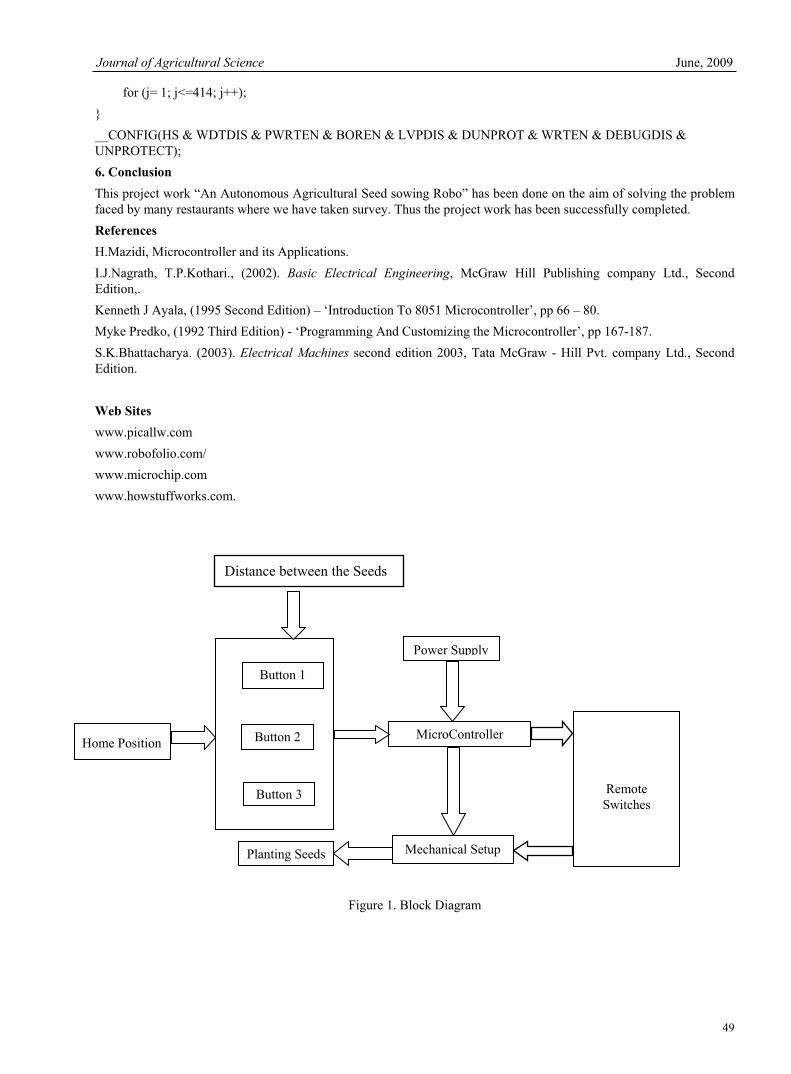
Journal of Agricultural Science June, 2009 33 Automation and Emerging Technology Development of 2d Seed Sowing Robo S.Chandika ME AMIE Department of Mechatronics Engg Kongu Engineering College Perundurai, Erode 638 052, Tamilnadu, India Tel: 99-421-807-27 E-mail: [email protected] T.Mohanraj Department of Mechatronics Engg Kongu Engineering College Perundurai, Erode 638 052, Tamilnadu, India E-mail: [email protected] Abstract In the current scenario most of the countries do not have sufficient skilled manpower specifically in agricultural sector and it affects the growth of developing countries. So it’s a time to automate the sector to overcome this problem. An innovative idea of our project is to automate the process of sowing crops such as sunflower, baby corn, groundnut and vegetables like beans, lady’s finger, pumpkin and pulses like black gram, green gram etc to reduce the human effort and increase the yield. The plantations of seeds are automatically done by using DC motor. The distance between the two seeds are controlled and varied by using Microcontroller. It is also possible to cultivate different kinds of seeds with different distance. When the Robo reaches the end of the field we can change the direction with the help of remote switches. The whole process is controlled by Microcontroller. Keywords: Agricultural Robo, Automation, DC motor and Microcontroller 1. Objective Automation brings comfort to our life. Automation in its pure sense defines any activity that minimizes human factor to increase productivity at consistent quality. The main fact is that how fast the process is being completed. This project “An Autonomous Agricultural Seed Sowing Robo” aims in fulfilling the lack of man power and automate the process of seed sowing with low cost. 2. Need Low Cost Automation (LCA), the buzzword in all industrial firms generally involves pneumatic, electrical as well as electronic components. LCA is important in the automation of factories, for example, the electronic component assembly plants. Automation saves a lot of tedious manual work and speeds up the production processes. Now days we have a problem on lack of man power. So agricultural field we spent more money for both planting especially seed sowing. It consumes more time and also increase the cost with low accuracy. So it is a time to automate the process of sowing. 3. Block Diagram The block diagram shown in Fig. 1, which consists of selection buttons for choosing the distance between the seeds, Microcontroller unit, power supply unit and mechanical setup (Robo). The power supply unit consists of step down transformer, rectifier circuit, filter and regulator. The robo consists of motors to drive the robo and stepper motor to
Transcript of Automation and Emerging Technology Development of 2d Seed ...

Journal of Agricultural Science June, 2009
33
Automation and Emerging Technology Development
of 2d Seed Sowing Robo
S.Chandika ME AMIEDepartment of Mechatronics Engg
Kongu Engineering College Perundurai, Erode 638 052, Tamilnadu, India
Tel: 99-421-807-27 E-mail: [email protected]
T.MohanrajDepartment of Mechatronics Engg
Kongu Engineering College Perundurai, Erode 638 052, Tamilnadu, India
E-mail: [email protected]
Abstract In the current scenario most of the countries do not have sufficient skilled manpower specifically in agricultural sector and it affects the growth of developing countries. So it’s a time to automate the sector to overcome this problem. An innovative idea of our project is to automate the process of sowing crops such as sunflower, baby corn, groundnut and vegetables like beans, lady’s finger, pumpkin and pulses like black gram, green gram etc to reduce the human effort and increase the yield. The plantations of seeds are automatically done by using DC motor. The distance between the two seeds are controlled and varied by using Microcontroller. It is also possible to cultivate different kinds of seeds with different distance. When the Robo reaches the end of the field we can change the direction with the help of remote switches. The whole process is controlled by Microcontroller. Keywords: Agricultural Robo, Automation, DC motor and Microcontroller 1. Objective Automation brings comfort to our life. Automation in its pure sense defines any activity that minimizes human factor to increase productivity at consistent quality. The main fact is that how fast the process is being completed. This project “An Autonomous Agricultural Seed Sowing Robo” aims in fulfilling the lack of man power and automate the process of seed sowing with low cost. 2. Need Low Cost Automation (LCA), the buzzword in all industrial firms generally involves pneumatic, electrical as well as electronic components. LCA is important in the automation of factories, for example, the electronic component assembly plants. Automation saves a lot of tedious manual work and speeds up the production processes. Now days we have a problem on lack of man power. So agricultural field we spent more money for both planting especially seed sowing. It consumes more time and also increase the cost with low accuracy. So it is a time to automate the process of sowing. 3. Block Diagram The block diagram shown in Fig. 1, which consists of selection buttons for choosing the distance between the seeds, Microcontroller unit, power supply unit and mechanical setup (Robo). The power supply unit consists of step down transformer, rectifier circuit, filter and regulator. The robo consists of motors to drive the robo and stepper motor to

Vol. 1, No. 1 Journal of Agricultural Science
34
control the flow of seeds and DC motor to sow the seeds in the field. The following figure shows the block diagram of our project. 4. Description of Components 4.1. DC Motor An electric motor is a machine which converts electrical energy to mechanical energy. Its action is based on the principle that when a current-carrying conductor is placed in a magnetic field, it experiences a magnetic force whose direction is given by Fleming’s left hand rule. When a motor is in operation, it develops torque. This torque can produce mechanical rotation. DC motors are also like generators classified into shunt wound or series wound or compound wound motors. 4.2 Spur Gear Gears are used to transmit the power from one shaft to another shaft or between a shaft and a slide. This is accomplished by successively engaging teeth. Spur gears have straight teeth parallel to the axis and thus, subjected to axial thrust due to the tooth load. 4.3 Stepper Motor The operation of a stepper motor requires the presence of the following elements:
A control unit (a micro-processor for example) which supplies impulses the frequency of which is proportional to the speed of the motor. This applies equally to both directions of rotation;
A sequencer which will direct the impulses to the various motor coils. A power supply.
<Figure 1> 4.4 Gear Motor <Figure2> 4.5 Opto Isolator An opto-isolator (shown in Fig 3) is a device that uses a short optical transmission path to transfer a signal between elements of a circuit, typically a transmitter and a receiver, while keeping them electrically isolated — since the signal goes from an electrical signal to an optical signal back to an electrical signal, electrical contact along the path is broken. <Figure 3> A common implementation involves a LED and a phototransistor, separated so that light may travel across a barrier but electrical current may not. When an electrical signal is applied to the input of the opto-isolator, its LED lights, its light sensor then activates, and a corresponding electrical signal is generated at the output. Unlike a transformer, the opto-isolator allows for DC coupling and generally provides significant protection from serious over voltage conditions in one circuit affecting the other. 4.6 Power Supply UnitThe Power supply unit shown in Fig 4, which consists of filters, rectifiers and voltage regulators. Starting with an AC voltage, a steady DC voltage, is obtained by rectifying the ac voltage then filtering to a dc level and Finally Regulation is usually obtained from an IC voltage regulator unit, which takes a dc voltage and provides a somewhat lower dc voltage, which remains the same even if the input dc voltage varies or the output load connected to the dc voltage changes. <Figure 4> 4.6.1 Block Diagram For Power Supply A block diagram containing the parts of a typical power supply and the voltage point in the unit is shown below in the diagram 5. <Figure 5> The ac voltage, typically 230v is connected to transformer, which steps the ac voltage down to the level for desired dc output. A diode rectifier provides a full wave rectified Voltage that is initially filtered by a simple capacitive filter to produce a dc voltage. This resulting dc voltage usually has some ripple or ac voltage variation. A regulator Circuit can use this dc input to provide a regulated that not only has much ripple voltage. But also remain the same dc values even if the input dc voltage changes. This voltage Regulation is usually obtained using one of a number of popular voltage regulation IC Units.

Journal of Agricultural Science June, 2009
35
4.6.2 Transformer A transformer is the static device of which electric power in one circuit is transformed into electric power of the same frequency in another circuit. It can rise or lower the voltage in a circuit but with a corresponding decrease or increase in current. It works with the principles of mutual induction. In our project we are using step down transformer for providing that necessary supply for the electronic circuits. 4.6.3 Rectifier The full wave rectifier conducts during both positive and negative half cycles of input AC input; two diodes are used in this circuit. The ac voltage is applied through a suitable power transformer with proper turn’s ratio. For the proper operation of the circuit, a center-tap on the secondary winding of the transformer is essential. During the positive half cycle of ac input voltage, the diode D1 will be forward biased and hence will conduct; while diode D2 will be reverse biased and will act as open circuit and will not conduct. In the next half cycle of ac voltage, polarity reverses and the diode D2 conducts, being forward biased, while D1 does not, being reverse biased. Hence the load current flows in both half cycles of ac voltage and in the same direction. The diode we are using here for the purpose of rectification is IN4001. 4.6.4 FilterThe filter circuit used here is the capacitor filter circuit where a capacitor is connected at the rectifier output, and a DC is obtained across it. The filtered waveform is essentially a DC voltage with negligible ripples, which is ultimately fed to the load. 4.6.5 Regulator The output voltage from capacitor is more filtered and finally regulated. The voltage regulator is a device, which maintains the output voltage constant irrespective of the change in supply variations, load variations and temperature changes. Hence IC7805 is used which is a +5v regulator. 4.7 Relays A relay is an electrically operated switch. Current flowing through the coil of the relay creates a magnetic field which attracts a lever and changes the switch contacts. The coil current can be on or off so relays have two switch positions and they are double throw (changeover) switches. Relays allow one circuit to switch a second circuit which can be completely separate from the first. For example a low voltage battery circuit can use a relay to switch a 230V AC mains circuit. There is no electrical connection inside the relay between the two circuits; the link is magnetic and mechanical. 4.8 PIC Microcontroller The microcontroller that has been used for this project is from PIC series. PIC microcontroller is the first RISC based microcontroller fabricated in CMOS (complementary metal oxide semiconductor) that uses separate bus for instruction and data allowing simultaneous access of program and data memory.The main advantage of CMOS and RISC combination is low power consumption resulting in a very small chip size with a small pin count. The main advantage of CMOS is that it has immunity to noise than other fabrication techniques. 4.8.1 PIC (16F877) <Figure 6> The above Fig.6 shows the architecture of PIC Micro controller 16F877. Various microcontrollers offer different kinds of memories. EEPROM, EPROM, FLASH etc. are some of the memories of which FLASH is the most recently developed. Technology that is used in pic16F877 is flash technology, so that data is retained even when the power is switched off. Easy Programming and Erasing are other features of PIC 16F877. 4.8.2 Special Features of PIC Micro controller The Core Features are • High-performance RISC CPU • Only 35 single word instructions to learn • All single cycle instructions except for program branches which are two cycle • Operating speed: DC - 20 MHz clock input DC - 200 ns instruction cycle • Up to 8K x 14 words of Flash Program Memory, Up to 368 x 8 bytes of Data Memory (RAM) Up to 256 x 8 bytes of EEPROM data memory

Vol. 1, No. 1 Journal of Agricultural Science
36
• Power-up Timer (PWRT) and Oscillator Start-up Timer (OST) • Watchdog Timer (WDT) with its own on-chip RC Oscillator for reliable operation • Programmable code-protection • Power saving SLEEP mode • Selectable oscillator options • Low-power, high-speed CMOS EPROM/EEPROM technology • Fully static design • In-Circuit Serial Programming (ICSP) via two pins • Only single 5V source needed for programming capability • In-Circuit Debugging via two pins • Processor read/write access to program memory • Wide operating voltage range: 2.5V to 5.5V • High Sink/Source Current: 25 mA • Commercial and Industrial temperature ranges • Low-power consumption: < 2mA typical @ 5V, 4 MHz 20mA typical @ 3V, 32 kHz < 1mA typical standby current
The Peripheral Features are • Timer0: 8-bit timer/counter with 8-bit pre scalar • Timer1: 16-bit timer/counter with prescaler, can be incremented during sleep via external crystal/clock • Timer2: 8-bit timer/counter with 8-bit period register, prescaler and postscaler • 10-bit multi-channel Analog-to-Digital converter • Synchronous Serial Port (SSP) with SPI. (Master Mode) and I2C. (Master/Slave) • Universal Synchronous Asynchronous Receiver Transmitter (USART/SCI) with 9- bit address detection. 5. Working <Figure 7> This part explains how the actual process is being done. The working of the project is explained below as follows: At The First Stage we should fill the seeds inside the container. Then select the button for distance between the seeds. When the power supply is given to the robo its start to move in the field. The time taken to reach the distance is feed into the microcontroller when it reaches the distance it will stop the robo by OFF the geared motor with the use of relay. Then the stepper motor is activated to control the flow of seeds which is kept inside the container after the flow of seed it will stopped by using relay. Finally the DC motor is activated to sow the seeds inside the field at the depth of 1 to 1.5 inches. Then the DC motor is stopped and Geared motor is activated and the process is repeated. The front part of the robo has only one wheel to easily change the direction. The change in direction is controlled by geared motor with the assistance of remote button. When the robo reaches the end if the field we can change the direction by using remote switches present in the robo. All the operation is controlled using Microcontroller. 5.1 Micro controller Program #include <pic.h> //#include "usart.h" #include <stdlib.h> //#define seed1delval 5 #define seed2delval 5 #define sowdelval 1500 #define countval 10 //8

Journal of Agricultural Science June, 2009
37
#define changestepdelval 5000 #define rightturndelval 15000 #define rightdelval 5000 #define stepdelayval 18000 #define movfor ((reverse = 0),(forward = 1),(enable_st = 1)) #define movrev ((forward = 0),(reverse = 1),(enable_st = 1)) #define stop (reverse = 0),(forward =0) // robot pin connections //#define l_opto (!l_opto1) //#define c_opto (!c_opto1) //#define r_opto (!r_opto1)
static volatile bit l_opto @ (unsigned)&PORTB*8+0; static volatile bit c_opto @ (unsigned)&PORTB*8+1; static volatile bit r_opto @ (unsigned)&PORTB*8+2; static volatile bit optoformovement @ (unsigned)&PORTB*8+5; static volatile bit rswitch @ (unsigned)&PORTE*8+0; // extra switches to turn the front motor manually to left and right static volatile bit lswitch @ (unsigned)&PORTE*8+1; static volatile bit forward @ (unsigned)&PORTA*8+2; static volatile bit reverse @ (unsigned)&PORTA*8+4; static volatile bit right @ (unsigned)&PORTA*8+1; static volatile bit left @ (unsigned)&PORTA*8+0; static volatile bit enable_st @ (unsigned)&PORTE*8+1; static volatile bit enable_tr @ (unsigned)&PORTE*8+2;
static volatile bit led1 @ (unsigned)&PORTC*8+3; static volatile bit led2 @ (unsigned)&PORTC*8+2; static volatile bit led3 @ (unsigned)&PORTC*8+4; static volatile bit led4 @ (unsigned)&PORTC*8+5; static volatile bit buzzer @ (unsigned)&PORTC*8+0; static volatile bit startswitch @ (unsigned)&PORTA*8+3; static volatile bit stopswitch @ (unsigned)&PORTE*8+2; static volatile bit r_switch @ (unsigned)&PORTE*8+0; static volatile bit l_switch @ (unsigned)&PORTE*8+1; static volatile bit sowswitch @ (unsigned)&PORTB*8+6; static volatile bit mode1 @ (unsigned)&PORTB*8+3; static volatile bit mode2 @ (unsigned)&PORTB*8+4; static volatile bit mode3 @ (unsigned)&PORTB*8+5; static volatile bit sowmotor @ (unsigned)&PORTC*8+1; static volatile unsigned char stepper @ &PORTD; static bit countcamebit, rbit, lbit; static unsigned char rotcount; unsigned char dummy,receiveddata;

Vol. 1, No. 1 Journal of Agricultural Science
38
void msdelay(unsigned int); void mswait (void); void stepdelay (void); void stepwait (void); void rotateclk(void); void rotateantclk(void); void turnright (void); void turnleft (void); void operation_move (void); void sowseed1 (void); void sowseed2 (void);
unsigned char noofrot; unsigned char i; static bit switchbit; unsigned char seed1delval;
void main() {// robo pins initialisation ADCON1 = 6; TRISA0 = 0; TRISA1 = 0; TRISA2 = 0; TRISA3 = 1; TRISA4 = 1; TRISA5 = 1;
TRISE0 = 1; TRISE1 = 1; TRISE2 = 1;
TRISB = 255;
TRISD0 = 0; TRISD1 = 0; TRISD2 = 0; TRISD3 = 0; TRISD4 = 0; TRISD5 = 0; TRISD6 = 0; TRISD7 = 0;

Journal of Agricultural Science June, 2009
39
TRISC0 = 0; TRISC1 = 0; TRISC2 = 0; TRISC3 = 0; TRISC4 = 0; TRISC5 = 0; // TRISC3 = 0; TRISC7 = 1;
forward = 0; reverse = 0; right = 0; left = 0; enable_st = 0; enable_tr = 0;
stepper = 0;
PORTC = 0; led1 = 0; led2 = 0; buzzer = 0; countcamebit = 0;
// robo initialisation ends
INTCON = 0; RBPU = 0; INTEDG = 0;
// usartinit(9600); // usarttx('H');
seed1delval = 5;
rbit = 0; lbit = 0; led1 = 1; led2 = 0; msdelay(1000); led1 =0; led2 =1; msdelay(1000); PORTC = 0;

Vol. 1, No. 1 Journal of Agricultural Science
40
led2 = 0;
while(!c_opto) { buzzer = 1; if(!rswitch) { if(!r_opto) { left = 0; right = 1; enable_tr = 1; } else { left = 0; right = 0; enable_tr = 0; } } else if (!lswitch) { if(!l_opto) { right = 0; left = 1; enable_tr = 1; } else { left = 0; right = 0; enable_tr = 0; } } else { left = 0; right = 0; enable_tr = 0; } } buzzer = 0; // led1 = 1;

Journal of Agricultural Science June, 2009
41
msdelay(2000); led1 = 0; led2 = 0; led3 = 0; while(startswitch) { if(!mode1) { led1 =1; led2 = 0; led3 = 0; seed1delval = 2; } else if(!mode2) { led1 =0; led2 = 1; led3 = 0; seed1delval = 5; } else if(!mode3) { led1 =0; led2 = 0; led3 = 1; seed1delval = 7; } }
while(startswitch); // led1 = 1; msdelay(200); while(!startswitch); movfor; while(1) { // while(!RCIF); // receiveddata= RCREG; while(r_switch && l_switch &&stopswitch) { for(i=0; i< seed1delval; i++) { msdelay(1000); if(!r_switch || !l_switch || !stopswitch)

Vol. 1, No. 1 Journal of Agricultural Science
42
{ switchbit = 1; break; } } if(switchbit) { break; } else { stop; sowseed1(); movfor; switchbit = 0; for(i=0; i< seed1delval; i++) { msdelay(1000); if(!r_switch || !l_switch |!stopswitch) { switchbit = 1; break; } } if(switchbit = 1) break; else { stop; sowseed2(); movfor; }
}
} if(switchbit) { switchbit = 0; if(!r_switch) {
// stop; led2 = 1;
Journal of Agricultural Science June, 2009
43
turnright(); led2 = 0; } else if(!l_switch) { // stop; led3= 1; turnleft(); led3 = 0; } else if(!stopswitch) { led1 = 0; stop; msdelay(200); while(!stopswitch); msdelay(200); while(startswitch); led1 = 1; msdelay(200); while(!startswitch); movfor;
} }
// if(!r_switch) // { // receiveddata= 'R'; // operation_move(); // msdelay(200); // while(!r_switch); // msdelay(200); // } // else if(!l_switch) // { // receiveddata= 'L'; // operation_move(); // msdelay(200); // while(!l_switch); // msdelay(200); // }
}

Vol. 1, No. 1 Journal of Agricultural Science
44
}
void sowseed1 (void) { noofrot = 4; rotateclk(); msdelay(2000); // noofrot = 1; // rotateclk(); sowmotor = 1; msdelay(sowdelval); sowmotor = 0; msdelay(1000); noofrot = 4; rotateantclk(); }
void sowseed2 (void) { noofrot = 4; rotateantclk(); msdelay(2000); // noofrot = 1; // rotateclk(); sowmotor = 1; msdelay(sowdelval); sowmotor = 0; msdelay(1000); noofrot = 4; rotateclk(); }
void turnright (void) { movfor; receiveddata = 'R'; operation_move(); msdelay(rightturndelval); receiveddata = 'S'; operation_move(); movfor; msdelay(rightdelval); receiveddata = 'R'; operation_move();

Journal of Agricultural Science June, 2009
45
msdelay(rightturndelval); receiveddata = 'S'; operation_move(); movfor; }void turnleft (void) { movfor; receiveddata = 'L'; operation_move(); msdelay(rightturndelval); receiveddata = 'S'; operation_move(); movfor; msdelay(rightdelval); receiveddata = 'L'; operation_move(); msdelay(rightturndelval); receiveddata = 'S'; operation_move(); movfor; }void operation_move(void) { switch (receiveddata) { case 'F': movfor; break;
case 'B': movrev; break;
case 'R': rbit = 1; while(!r_opto) { left = 0; right = 1; enable_tr = 1; // if(RCIF) // { /// receiveddata = RCREG;

Vol. 1, No. 1 Journal of Agricultural Science
46
// continue; // } } left = 0; right = 0; enable_tr = 0; rbit = 1; lbit = 0; break; case 'L': lbit = 1; while(!l_opto) { right = 0; left = 1; enable_tr = 1; // if(RCIF) // { // receiveddata = RCREG; // continue; // } } left = 0; right = 0; enable_tr = 0; lbit = 1; rbit = 0; break; case 'S': if (rbit) { while(!c_opto) { right = 0; left = 1; enable_tr = 1; } left = 0; right = 0; enable_tr = 0; msdelay(400); rbit = 0; } if(lbit)

Journal of Agricultural Science June, 2009
47
{ while(!c_opto) { left = 0; right = 1; enable_tr = 1; } left = 0; right = 0; enable_tr = 0; msdelay(400); lbit = 0; } stop; break;
default: break; } }void interrupt intl() { if (INTF) { rotcount++; countcamebit = 1; INTF = 0; } }void rotateantclk(void) {unsigned int i; for (i=1; i<=noofrot; i++) { stepper = 0x10; stepdelay(); stepper = 0x20; stepdelay(); stepper = 0x40; stepdelay(); stepper = 0x80; stepdelay(); } }

Vol. 1, No. 1 Journal of Agricultural Science
48
void rotateclk(void) {unsigned int i; for (i=1; i<=noofrot; i++) { // stepper = 0x0ff; // while(1); stepper = 0x80; stepdelay(); stepper = 0x40; stepdelay(); stepper = 0x20; stepdelay(); stepper = 0x10; stepdelay(); } }
void stepdelay (void) { static unsigned int i; for (i = 1; i<=stepdelayval; i++) stepwait (); }
void stepwait (void) {;}
void msdelay (unsigned int msdel) { unsigned int i; for (i = 1; i<=msdel; i++) mswait (); i += 2000; // a dummy instruction for correct time delay; i +=20; }
void mswait (void) { unsigned int j;
Journal of Agricultural Science June, 2009
49
for (j= 1; j<=414; j++); }__CONFIG(HS & WDTDIS & PWRTEN & BOREN & LVPDIS & DUNPROT & WRTEN & DEBUGDIS & UNPROTECT); 6. Conclusion This project work “An Autonomous Agricultural Seed sowing Robo” has been done on the aim of solving the problem faced by many restaurants where we have taken survey. Thus the project work has been successfully completed. References H.Mazidi, Microcontroller and its Applications. I.J.Nagrath, T.P.Kothari., (2002). Basic Electrical Engineering, McGraw Hill Publishing company Ltd., Second Edition,. Kenneth J Ayala, (1995 Second Edition) – ‘Introduction To 8051 Microcontroller’, pp 66 – 80. Myke Predko, (1992 Third Edition) - ‘Programming And Customizing the Microcontroller’, pp 167-187. S.K.Bhattacharya. (2003). Electrical Machines second edition 2003, Tata McGraw - Hill Pvt. company Ltd., Second Edition.
Web Sites www.picallw.com www.robofolio.com/ www.microchip.com www.howstuffworks.com.
Figure 1. Block Diagram
Planting Seeds
MicroController
Button 1
Button 2
Button 3
Home Position
Distance between the Seeds
Remote Switches
Power Supply
Mechanical Setup

Vol. 1, No. 1 Journal of Agricultural Science
50
Figure 2. Gear Motor
Figure 3. Opto Isolator
Figure 4. Power Supply
Figure 5. General Block Diagram
Specifications:
Type - DC Geared Motor
Voltage - 5V
Current - 110mA
Rpm - 150 RPM
Transformer Rectifier Filter Regulator

Journal of Agricultural Science June, 2009
51
Figure 6. Architecture of PIC Micro controller

Vol. 1, No. 1 Journal of Agricultural Science
52
Figure 7. Photographic view of the Experimental Setup