Automatic Washroom Light Controller - Online … · Automatic Washroom Light Controller . ......
4
International Journal of Scientific & Engineering Research, Volume 7, Issue 4, April-2016 234 ISSN 2229-5518 IJSER © 2016 http://www.ijser.org Automatic Washroom Light Controller Sayantan Sarkar, Tathagata Biswas, Mainak Biswas, Debasish Jana Abstract— This paper presents the electronic trigging of atomatic washroom light switching which replaces manual switching of washroom light .Using microprocessor and NPN transistor the switching control is done. It has been established that automatic washroom light controller using motion sensor was commercially productive but with few drawbacks listing high power consumption and cost effective which has been replaced by automatic electronic triggering. Index Terms— Automic controller, Voltage divider, electromagnetic relay, ATMEGA series microprocessor —————————— —————————— 1 INTRODUCTION n this dynamic world, the first objective of following paper strains on the economic condition of power consumption. Especilly for countries like India where power production and demand is craving its peek, it is necessary to develop such system and devices that can be produced commercially with minimized power consumtion to meet the future power re- quirements. In view of energy crises throughout the world, judicious planning for effective utilization of divices, technol- ogy using different renewable resources is essential. In the booming technological world home automation has become the most popular as well as economic in saving electrical in once daily life.This paper represents the simple operation of an intelligent electronic microprocessor that is programmed to control the washfoom light using an electromagnetic relay coil. Our earlier research work on automatic washroom light con- troller was fuzzy based technique using reed switch, electro- magnetic relay coil on door hinges which was replaced by this paper. The aim of this paper is minimizing power consump- tion and cost effective. 2 THREOMS AND PROOFS 2.1 Variation of sensivityof TX-RX sensors The prime theorem used for varying the sensivity of the TX- RX sensors so as to clearly define for the microprosser is volt- age divider rule. Voltage Divider Theorem. A voltage divider is also known as potential divider. It is a simple electrical circuit that contains a high resistance across a voltage source. We obtain the variable voltage output across the resistance by varying position of sliding contact on the resistance. This output voltage is a fraction of source voltage. Voltage divider rule is applicable for both AC and DC voltage source. Proof. Vout = V1 (IR2 /I(R1 +R2 )) =V1 R2 /(R1 +R2 ) [1] Vout = V1 (IR2 /I(R1 +R2 )) = V1 (R1 ||RL)/(R1 +R2 ||RL ) [2] 2.2 Feeding controlling signal through NPN transistor For controlling, the DC operated electromagnetic 12V relay on NPN transistor is used as a switchinh element. The transistor is configured as common emitter so as to amplify signal as well as to control the relay. _________________________ [1] Output Voltage under no load (open circuit) [2] Output Voltage under load I ———————————————— • Sayantan Sarkar is currently pursuing bachelor degree in electrical and electronics engineering in West Bengal UniversityOf Technology , India, PH-9038497233, E-mail: [email protected] • Tathagata Biswas is currently pursuing bachelor degree in electrical and electronics engineering in West Bengal UniversityOf Technology , India, PH-8981975022. E-mail: [email protected] IJSER
Transcript of Automatic Washroom Light Controller - Online … · Automatic Washroom Light Controller . ......
International Journal of Scientific & Engineering Research, Volume 7, Issue 4, April-2016 234 ISSN 2229-5518
IJSER © 2016 http://www.ijser.org
Automatic Washroom Light Controller
Sayantan Sarkar, Tathagata Biswas, Mainak Biswas, Debasish Jana
Abstract— This paper presents the electronic trigging of atomatic washroom light switching which replaces manual switching of washroom light .Using microprocessor and NPN transistor the switching control is done. It has been established that automatic washroom light controller using motion sensor was commercially productive but with few drawbacks listing high power consumption and cost effective which has been replaced by automatic electronic triggering.
Index Terms— Automic controller, Voltage divider, electromagnetic relay, ATMEGA series microprocessor
—————————— ——————————
1 INTRODUCTION n this dynamic world, the first objective of following paper strains on the economic condition of power consumption. Especilly for countries like India where power production
and demand is craving its peek, it is necessary to develop such system and devices that can be produced commercially with minimized power consumtion to meet the future power re-quirements. In view of energy crises throughout the world, judicious planning for effective utilization of divices, technol-ogy using different renewable resources is essential. In the booming technological world home automation has become the most popular as well as economic in saving electrical in once daily life.This paper represents the simple operation of an intelligent electronic microprocessor that is programmed to control the washfoom light using an electromagnetic relay coil. Our earlier research work on automatic washroom light con-troller was fuzzy based technique using reed switch, electro-magnetic relay coil on door hinges which was replaced by this paper. The aim of this paper is minimizing power consump-tion and cost effective.
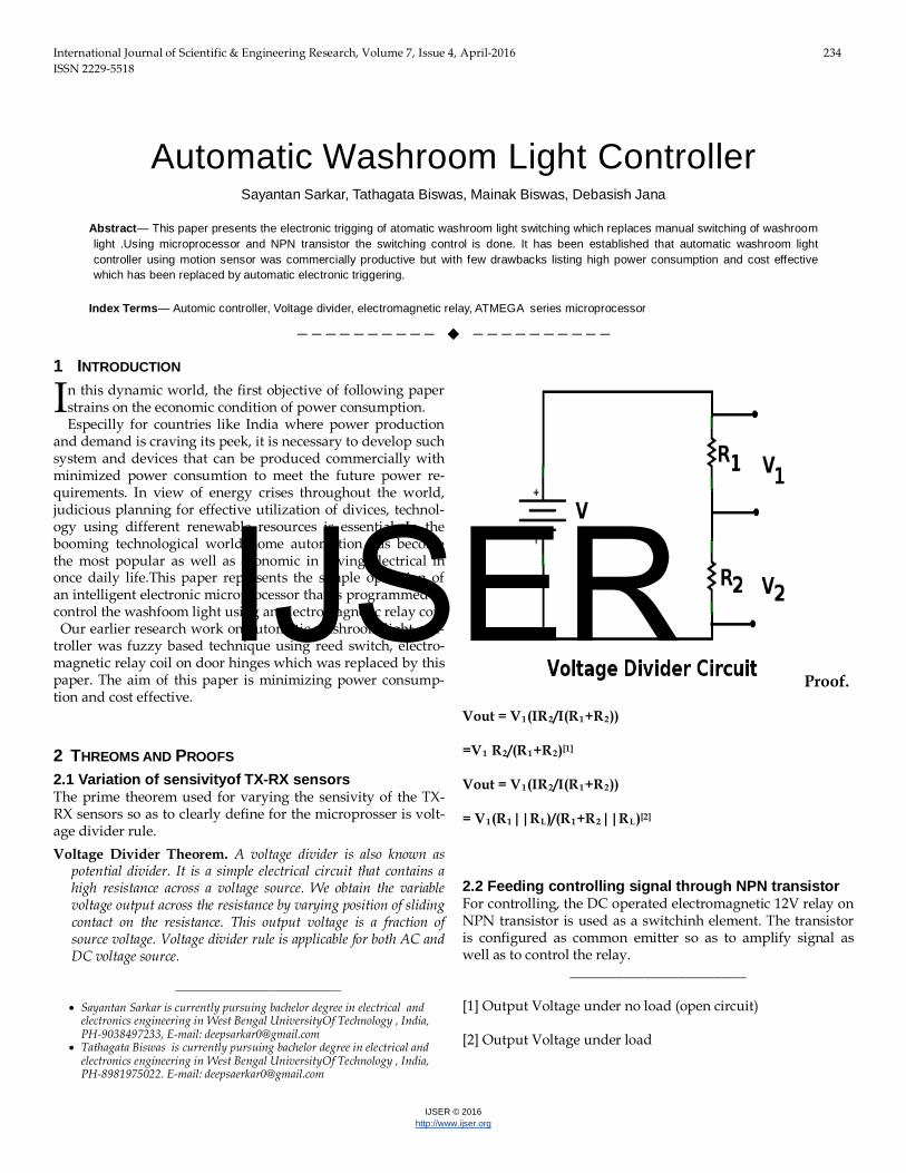
2 THREOMS AND PROOFS 2.1 Variation of sensivityof TX-RX sensors The prime theorem used for varying the sensivity of the TX-RX sensors so as to clearly define for the microprosser is volt-age divider rule. Voltage Divider Theorem. A voltage divider is also known as
potential divider. It is a simple electrical circuit that contains a high resistance across a voltage source. We obtain the variable voltage output across the resistance by varying position of sliding contact on the resistance. This output voltage is a fraction of source voltage. Voltage divider rule is applicable for both AC and DC voltage source.
Proof. Vout = V1(IR2/I(R1+R2)) =V1 R2/(R1+R2)[1] Vout = V1(IR2/I(R1+R2)) = V1(R1||RL)/(R1+R2||RL)[2]
2.2 Feeding controlling signal through NPN transistor For controlling, the DC operated electromagnetic 12V relay on NPN transistor is used as a switchinh element. The transistor is configured as common emitter so as to amplify signal as well as to control the relay.
_________________________ [1] Output Voltage under no load (open circuit) [2] Output Voltage under load
I
———————————————— • Sayantan Sarkar is currently pursuing bachelor degree in electrical and
electronics engineering in West Bengal UniversityOf Technology , India, PH-9038497233, E-mail: [email protected]
• Tathagata Biswas is currently pursuing bachelor degree in electrical and electronics engineering in West Bengal UniversityOf Technology , India, PH-8981975022. E-mail: [email protected]
IJSER
International Journal of Scientific & Engineering Research, Volume 7, Issue 4, April-2016 235 ISSN 2229-5518
IJSER © 2016 http://www.ijser.org
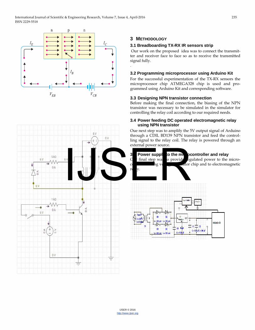
3 METHODOLOGY 3.1 Breadboarding TX-RX IR sensors strip Our work on the proposed idea was to connect the transmit-ter and receiver face to face so as to receive the transmitted signal fully. .
3.2 Programming microprocessor using Arduino Kit For the successful experimentation of the TX-RX sensors the microprocessor chip ATMEGA328 chip is used and pro-grammed using Arduino Kit and corresponding software. 3.3 Designing NPN transistor connection Before making the final connection, the biasing of the NPN transistor was necessary to be simulated in the simulator for controlling the relay coil according to our required needs.
3.4 Power feeding DC operated electromagnetic relay using NPN transistor
Oue next step was to amplify the 5V output signal of Arduino through a CDIL BD139 NPN transistor and feed the control-ling signal to the relay coil. The relay is powered through an external power source. 3.5 Power supply to the microcontroller and relay Our final step was to provide regulated power to the micro-controller using voltage regulator chip and to electromagnetic relay.
IJSER
International Journal of Scientific & Engineering Research, Volume 7, Issue 4, April-2016 236 ISSN 2229-5518
IJSER © 2016 http://www.ijser.org
3.6 Flowchart
4 HELPFUL HINTS 4.1 Arduino Kit Figure Arduino kit is a compact programming controller circuit gen-erally used by circuit developers basically used to program various microprocessor chip, feed various analog and digital inputs, provide necessary analog and digital inputs, provide necessary analog and digital output as well as to simulate var-ious electronic circuits.
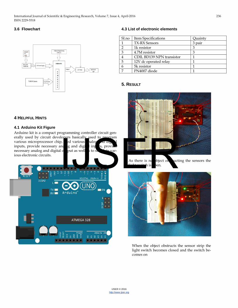
4.3 List of electronic elements Sl.no Item Specifications Quainty 1 TX-RX Sensors 3 pair 2 1k resistor 3 3 4.7M resistor 3 4 CDIL BD139 NPN transistor 1 5 12V dc operated relay 1 6 5k resistor 1 7 PN4007 diode 1 5. RESULT
As there is no object obstructing the sensors the light switch is open.
When the object obstructs the sensor strip the light switch becomes closed and the switch be-comes on
IJSER

International Journal of Scientific & Engineering Research, Volume 7, Issue 4, April-2016 237 ISSN 2229-5518
IJSER © 2016 http://www.ijser.org
6. FUTURE ENHANCEMENT In the rescarch we have designed a system to give complete solution for atomatic switching of washroom light. The watage of time for manual switching and energy can be eliminated and is one of the important criteria in once daily life. Using this rescarche unit we can also automate residential lightning and could seyup in small to big industries. 7 CONCLUSION The proposed system “Atomatic Washroom Light Controller” has been successfully designed and tested. It has been developed by integrating feature of all the hard-ware components used. Presence of every module has been reasoned out and placed carefully thus contributing to the best working of the unit.
8 END SECTIONS 8.1 Appendix
Colour Coding of resistance
8.2 Acknowledgment This work was supported by our respected electric depart-mental faculty Mr.Debashis Jana of Camellia Institute of Tecnology under West Bengal University of Technology. The work was also very much supported by our beloved class ma-te Shubhojit Kundu.
8.3 References [1] J.B Gupta, Electronic Devices and Circuits, “Optoelectronic devices”, Light
Emitting Diode, pp- 478-479. [2] J.B Gupta, Electronic Devices and Circuits, “Rectifiers”, Full Wave Rectifica-
tion, pp- 120-126. [3] J.B Gupta, Electronic Devices and Circuits, “Bipolar Junction Transistors”,
pp- 140-172. [4] A.Chakrabarti and S.Nath, “Basic Electrical and Electronic Engg I”,
DC Network Analysis, Voltage Divider, pp- 1.5-1.6. [5] www.electronicshub.com, EEE project Ideas
IJSER