ATL: Atlas Transformation Language ATL Installation Guide - Eclipse

AutomatictransferswitchcontrollersATL series
100% electricity
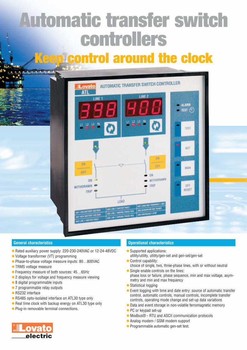
Rated auxiliary power supply: 220-230-240VAC or 12-24-48VDC Voltage transformer (VT) programming Phase-to-phase voltage measure inputs: 80…800VAC TRMS voltage measure Frequency measure of both sources: 45…65Hz 2 displays for voltage and frequency measure viewing 8 digital programmable inputs 7 programmable relay outputs RS232 interface RS485 opto-isolated interface on ATL30 type only Real time clock with backup energy on ATL30 type only Plug-in removable terminal connections.
General characteristics
Automatic transfer switchcontrollers
Keep control around the clock
Supported applications: utility/utility, utility/gen-set and gen-set/gen-set
Control capability:choice of single, two, three-phase lines, with or without neutral
Single enable controls on the lines:phase loss or failure, phase sequence, min and max voltage, asym-metry and min and max frequency
Statistical logging Event logging with time and date entry: source of automatic transfer
control, automatic controls, manual controls, incomplete transfercontrols, operating mode change and set-up data variations
Data and event storage in non-volatile ferromagnetic memory PC or keypad set-up Modbus® - RTU and ASCII communication protocols Analog modem / GSM modem support Programmable automatic gen-set test.
Operational characteristics

Description
Dual AC and DC power supply Universal battery supply 12V, 24V or 48VDC Control of three-phase systems, with or without neutral 7 different control parameters of the supply lines, individually acti-
vated Frequency measure on both lines Control relay of motorised circuit breakers or changeover switches Statistical data recording related to lines, changeover systems and
utilities, indispensable for optimising the system and steady opera-tion
Event logging with date and time entry, fundamental for diagnosticswhenever breakdowns or malfunctions take place
Memory for permanent storage of logged data and events Programmable inputs and outputs available for generating sets
supervision and control Use and set-up ease Standard-supplied RS232 port for quick PC set-up Simultaneous use of both RS232 and RS485 ports.
Advantages
Automatic test Transfer strategy Gen-set starting supervision Two generator rotation Principal line selection Non priority loads disconnection Before and after transfer indication EJP (Effacement Jour Pointe - special energy tariff) signal supervi-
sion.
Programmable functions
Contactors Motorised circuit breakers Motorised changeover switches.
Transfer equipment capability
The ATL20 and ATL30 are designed and developed to control and supervise the automatic or manual transfer of a utilityload from a principal power supply source to a stand-by.Both units include all the necessary features to supervise and control power supply sources, composed by energy distribu-tion systems or generating sets, and the relative transfer equipment, such as contactors, motorised circuit breakers andchangeover switches.The utility changeover, from one power source to the other, can be automatic or manual. The automatic transfer takes placewhenever conditions predefined by the user take place, for example:- power supply source not respecting programmed limits- the need to have a very reliable power source- the need to use the most economical power source.All the operations for set-up, operating mode change, manual transfer controls and operating checks can also be conduc-ted, via personal computer, by using the specific remote control software.There are two models available, the base unit ATL20 and the more complete unit ATL30; both come equipped with DC andAC power supply inputs.The more complete ATL30 has the following features, not available on the ATL20 type:- RS485 opto-isolated interface in addition to the standard RS232 port- Real time clock with backup energy.

Technical characteristics
How to order
Dimensions [mm]
Auxiliary power supplyDC supply 12...48VDCAC supply 220...240VACFrequency 45…65HzPower consumption max 6VA (Us: 240VAC)Power dissipation max 2.8W (Us: 48VDC or Us: 240VAC)Current consumption max 420mA at 12VDC; 200mA at 24VDC
100mA at 48VDCMicro-breaking immunity time 50msVoltage inputsRated voltage Ue 690VAC phase-phase
(400VAC phase-neutral)Measure limits 80…800VAC phase-phaseFrequency limits 45…65HzType of measure TRMSMeasure input impedance >1.1MΩ phase-phase;
>0.5MΩ phase-neutralType of connection One, two or three phase Measure error Class 0.5 ±0.25% f.s. ±1digitDigital inputsNumber of inputs 8 (all programmable)Type of input NegativeInput current ≤10mAInput signal “0” state ≤1.5 (2.9V typical)Input signal “1” state ≥5.3 (4.3V typical)Input signal delay ≥50msecRelay outputsNumber of outputs 7 (all programmable)Number of control outputs 2 (1 N/O - rated 12A 250VAC)for circuit breaker opening (relay contacts rated 16A AC1 250V/B300)and pre-charging ❶Number of control outputs 2 relays (1 NO - rated 8A AC1 250V/B300; for circuit breaker closing ❶ 1A 30VDC pilot duty)Number of control outputs 1 relay (1 NO - rated 8A AC1 250V/B300;for generating set ❶ 1A 30VDC pilot duty)Number of spare outputs ❶ 1 relay (1 C/O - rated 8A AC1 250V/B300;
1A 30VDC pilot duty)Number of alarm outputs ❶ 1 relay (1 C/O - rated 8A AC1 250V/B300;
1A 30VDC pilot duty)
Communication interfacesRS232 serial port Programmable baud-rate 1200…38400 bps
Connection by RJ6/6 plugRS485 serial port (ATL30 only) Opto-isolated, programmable baud-rate
1200…38400 bpsConnection by plug-in/removable terminal
Real time clock (ATL30 only)Type of backup energy Capacitor (Super Cap)Operating autonomy 12...15 dayswithout power supply InsulationRated insulation voltage Ui 690VAmbient conditionsOperating temperature -20…+60°CStorage temperature -30…+80°CRelative humidity <90% Pollution degree maximum 3ConnectionsType of terminal Plug-in / removableConductor section min/max 0.2…2.5 mm2 (24 - 12 AWG)Tightening torque 0.5 Nm (4.5 lbin)HousingMaterial ThermoplasticVersion Flush mountDegree of protection IP41 on front, IP20 rearCertifications and complianceCertifications obtained cULus - GostCompliant with standards IEC/EN 60947-1, IEC/EN 60947-6-1,
IEC/EN 61000-6-2, IEC/EN 61000-6-3.❶ All outputs are programmable.
Order code Description Quantity Weightper package [kg]
Automatic transfer switchesATL20 A240 ❷ Type with RS232 port 1 0.950ATL30 A240 ❷ Type with RS232 and RS485 port and real time clock 1 0.950Remote control softwareATL SW PC software for set-up and remote control, complete with PC-ATL connecting cable (51 C2) via RS232 port 1 0.246Accessories51 C2 PC-ATL connecting cable, 1.8m long 1 0.09051 C4 PC-PX1 connecting cable, 1.8m long (ATL30 A240 only) 1 0.14751 C5 ATL-modem connecting cable, 1.8m long (ATL30 A240 only) 1 0.11151 C6 ATL (RS232 port)-PX1 connecting cable, 1.8m long (ATL30 A240 only) 1 0.10251 C9 PX1-modem connecting cable, 1.8m long (ATL30 A240 only) 1 0.1374 PX1 RS232/RS485 converter drive, opto-isolated 220-240VAC ❸ (ATL30 A240 only) 1 0.60031 PACR IP54 front protection cover 1 0.107❷ Other supply voltage on request. Contact our Customer Service (Tel. +39 035 4282422) for details.❸ 110-120VAC supply on request. Contact our Customer Service (Tel. +39 035 4282422) for details.
LOAD
ATL
ON
OFF
ALARM
TEST
TEST
AUT
MAN
OFFRESET
ON
OFF
L1 L2 L3 Hz L1 L2 L3 Hz
LINE 2LINE 1
ON
WITHDRAWN
TRIP
ON
WITHDRAWN
TRIP
AUTOMATIC TRANSFER SWITCH CONTROLLER
A01 LOW BATTERY VOLTAGE A04 LINE 2 SWITCH FAULT A07 LOAD NOT POWERED T. OUT
A02 HIGH BATTERY VOLTAGE A05 LINE 1 WRONG PHASE SEQ. A08 GENERATOR NOT READY
A03 LINE 1 SWITCH FAULT A06 LINE 2 WRONG PHASE SEQ. A09 EMERGENCY STOP
144
144
138.
5
138.5
79
3194
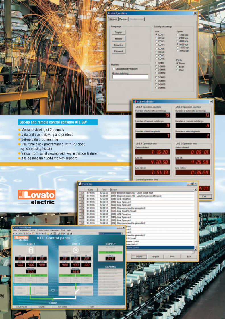
Measure viewing of 2 sources Data and event viewing and printout Set-up data programming Real time clock programming, with PC clock
synchronising feature Virtual front panel viewing with key activation feature Analog modem / GSM modem support.
Set-up and remote control software ATL SW

PD39
GB
01 0
7
LOVATO ELECTRIC S.P.A.CONTROL SOLUTIONS FOR INDUSTRY
VIA DON E. MAZZA, 1224020 GORLE (BERGAMO)ITALY
Tel. +39 035 4282111Fax +39 035 4282200E-mail [email protected]
Sales Department:Tel. +39 035 4282354Fax +39 035 4282400
The products described in thispublication are subject to be revised orimproved at any moment.Catalogue descriptions and details, suchas technical and operational data,drawings, diagrams and instructions,etc., do not have any contractual value. Inaddition, products should be installed andused by qualified personnel and in com-pliance with the regulations in force forelectrical systems in order to avoiddamages and safety hazards.
www.LovatoElectric.com
Planet-SWITCHPlanet-SWITCHPlanet-SWITCHPlanet-SWITCHPlanet-SWITCHPlanet-SWITCH• Motor protection
circuit breakers• Switch disconnectors• Contactors• Motor protection relays• Electromechanical starters• Push buttons and selectors• Limit, micro and foot switches• Rotary cam switches
• Modular contactors• Time relays• Protection relays• Level control relays• Earth leakage relays
• Digital metering instrumentsand current transformers
• Soft starters• AC motor drives• Automatic power
factor controllers• Automatic battery chargers• Automatic transfer switch
controllers• Programmable logic relays• Generating set controllers
Planet-DINPlanet-DINPlanet-DINPlanet-DINPlanet-DINPlanet-DIN
Planet-LOGICPlanet-LOGICPlanet-LOGICPlanet-LOGICPlanet-LOGICPlanet-LOGIC
Contactors
Digital instruments
Push buttons and selectors
Protection relays
Rotary cam switches
100% electricity
Automatic battery chargers


![Linear actuators ATL Series and BSA Series - … · 42 2 2.2 TECHNICAL DATA - acme screw linear actuators ATL Series SIZE ATL 20 ATL 25 ATL 28 ATL 30 ATL 40 Push rod diameter [mm]](https://static.fdocuments.us/doc/165x107/5b5e55147f8b9a8b4a8c1cc7/linear-actuators-atl-series-and-bsa-series-42-2-22-technical-data-acme.jpg)