Automatic Test Case Generator in XML from Specifications ... · PDF fileAutomatic Test Case...
36
© Information & Telecommunications Technology Center (ITTC), EECS, University of Kansas Automatic Test Case Generator in XML from Specifications in Rosetta Masters Thesis Defense by Murthy Kakarlamudi January 10, 2003 Thesis Committee Dr. Perry Alexander (Chair) Dr. Susan Gauch Dr. David Andrews
-
Upload
nguyenkiet -
Category
Documents
-
view
253 -
download
5
Transcript of Automatic Test Case Generator in XML from Specifications ... · PDF fileAutomatic Test Case...
© Information & Telecommunications Technology Center (ITTC), EECS, University of Kansas1
Automatic Test Case Generator in XML from Specifications in Rosetta
Masters Thesis Defense by
Murthy Kakarlamudi
January 10, 2003
Thesis CommitteeDr. Perry Alexander (Chair)
Dr. Susan GauchDr. David Andrews
© Information & Telecommunications Technology Center (ITTC), EECS, University of Kansas2
Overview
• Introduction• Problem Statement• Background Details
• Details of Rosetta• Details of XML
• Test Scenarios• Test Requirements• Abstract Test Vectors• Concrete Test Vectors• Summary and Future Work
© Information & Telecommunications Technology Center (ITTC), EECS, University of Kansas3
Introduction
• Importance of Testing• General Testing Techniques
• Implementation Based Techniques• Specification Based Techniques
• Complex Systems• Problem: Difficulty in Representation• Possible solution: Increasing the Abstraction Levels• Solution: System Level Design Languages• Rosetta
© Information & Telecommunications Technology Center (ITTC), EECS, University of Kansas4
Introduction…
• General Testing Technique• Test cases executed on the developed product
• Problem - Tedious and Repetitious
• Why? – Underlying Implementation Changes
• Solution - Automatic Test Case Generation
• Tools - Automatic Test Case Generator
© Information & Telecommunications Technology Center (ITTC), EECS, University of Kansas5
Problem Statement…
• Automatic Test Case Generators - Problems• Test cases in language dependent format• Problem integrating third party tools
• Answer - Language Independence
• Uses - Simulation Environment Independent• Proposed Solution
• Specifications in Rosetta• Test cases in XML

© Information & Telecommunications Technology Center (ITTC), EECS, University of Kansas6
Background ... Details Of Rosetta
• Facet• Basic unit of specification• Component representation from a particular perspective
facet <facet-label> (parameters) is <declarations> begin <domain> <terms> end facet <facet-label>
© Information & Telecommunications Technology Center (ITTC), EECS, University of Kansas7
Details of Rosetta…
• facet-label - Provides Unique Name• parameters - Facet Interfaces
• <variable-name> :: mode type• input_voltage :: in real
• declarations - Define Local Variables• domain - Provides Definitions and Vocabulary• terms - Define Behavior modeled by Facet
• Type – boolean or facet• label::term
• Term – expression
© Information & Telecommunications Technology Center (ITTC), EECS, University of Kansas8
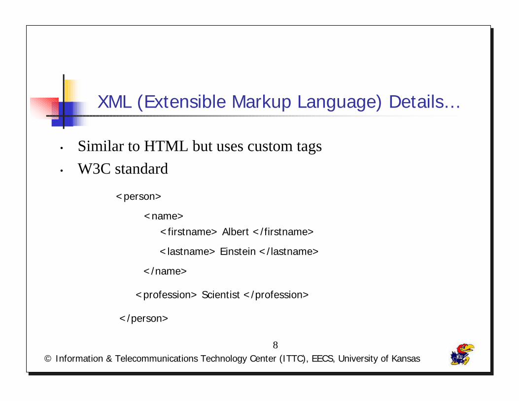
XML (Extensible Markup Language) Details…
• Similar to HTML but uses custom tags• W3C standard
<name>
</name>
<profession> Scientist </profession>
<person>
</person>
<firstname> Albert </firstname>
<lastname> Einstein </lastname>

© Information & Telecommunications Technology Center (ITTC), EECS, University of Kansas9
DTD, XSLT, DOM
• DTD – Document Type Definition• Template for XML• Determines Elements order• Uses – Exchange format
• XSLT – Extensible Style Sheet Transformation• Transform XML documents• Contains templates and associated rules
• DOM – Document Object Model• XML Document in memory• Object Tree Representation
© Information & Telecommunications Technology Center (ITTC), EECS, University of Kansas10
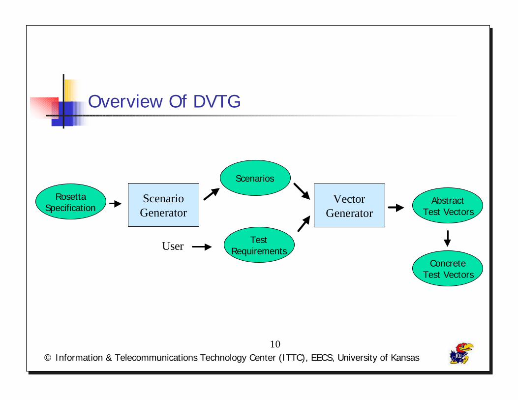
Overview Of DVTG
RosettaSpecification
Scenarios
TestRequirements
VectorGenerator
AbstractTest Vectors
ScenarioGenerator
UserConcrete
Test Vectors
© Information & Telecommunications Technology Center (ITTC), EECS, University of Kansas11
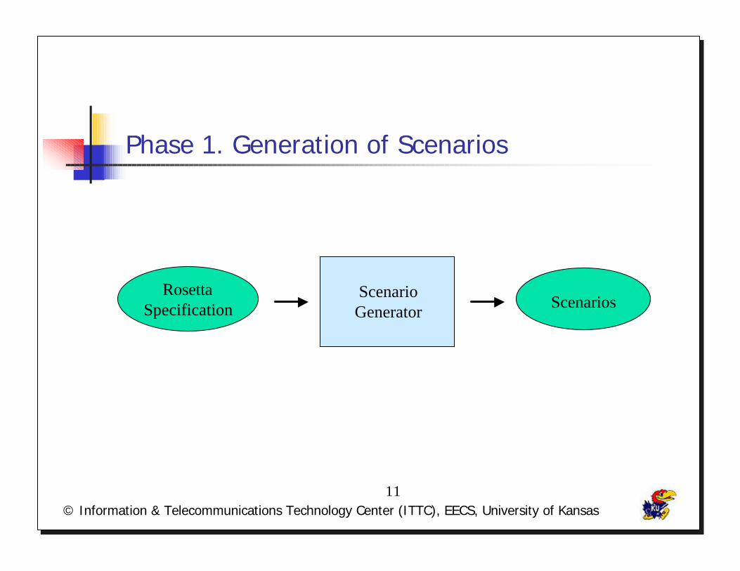
Phase 1. Generation of Scenarios
RosettaSpecification
ScenarioGenerator Scenarios
© Information & Telecommunications Technology Center (ITTC), EECS, University of Kansas12
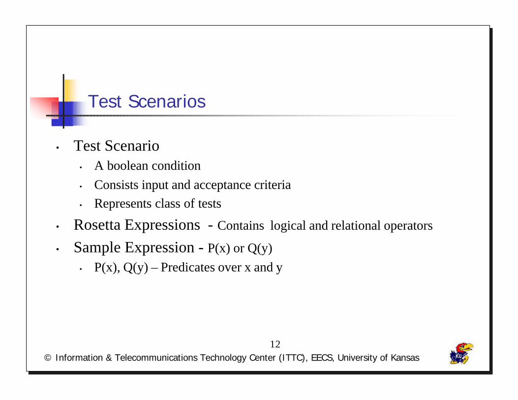
Test Scenarios
• Test Scenario• A boolean condition• Consists input and acceptance criteria• Represents class of tests
• Rosetta Expressions - Contains logical and relational operators
• Sample Expression - P(x) or Q(y)• P(x), Q(y) – Predicates over x and y
© Information & Telecommunications Technology Center (ITTC), EECS, University of Kansas13
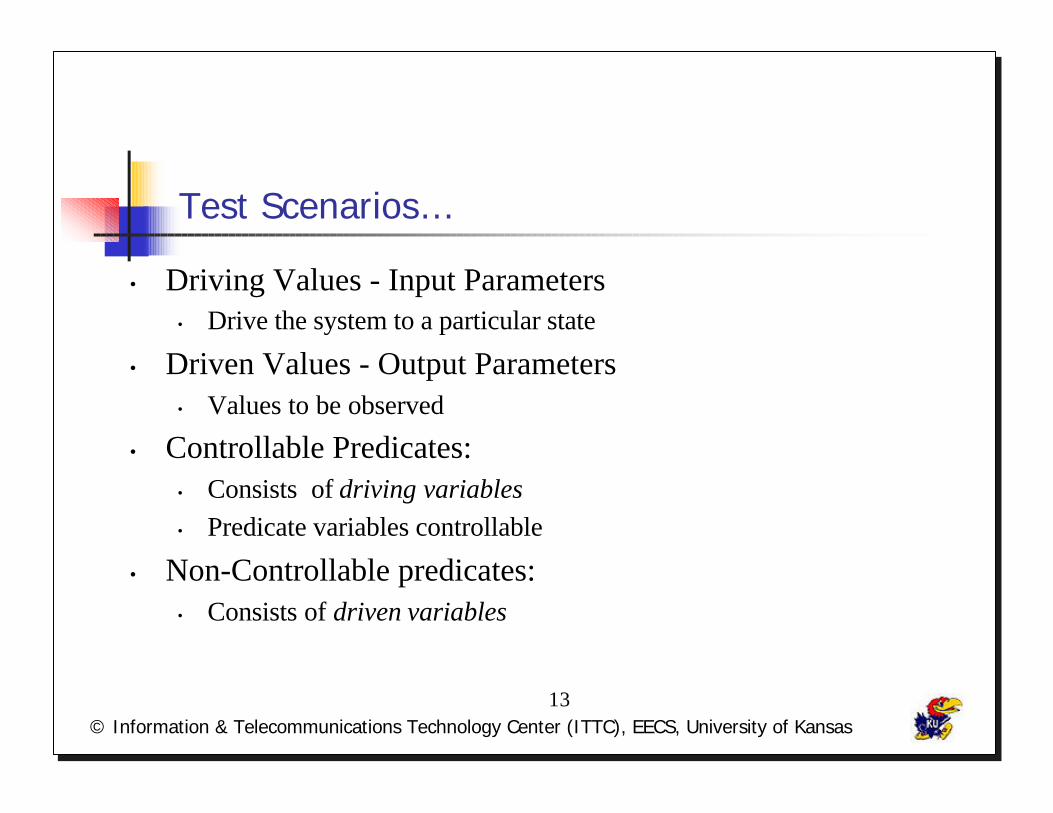
Test Scenarios…
• Driving Values - Input Parameters• Drive the system to a particular state
• Driven Values - Output Parameters• Values to be observed
• Controllable Predicates:• Consists of driving variables• Predicate variables controllable
• Non-Controllable predicates:• Consists of driven variables
© Information & Telecommunications Technology Center (ITTC), EECS, University of Kansas14
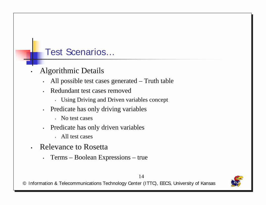
Test Scenarios…
• Algorithmic Details• All possible test cases generated – Truth table• Redundant test cases removed
• Using Driving and Driven variables concept
• Predicate has only driving variables• No test cases
• Predicate has only driven variables• All test cases
• Relevance to Rosetta• Terms – Boolean Expressions – true
© Information & Telecommunications Technology Center (ITTC), EECS, University of Kansas15
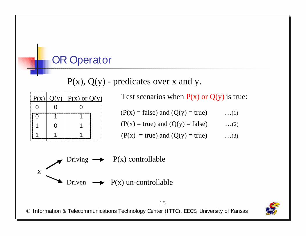
OR Operator
P(x), Q(y) - predicates over x and y.
P(x) Q(y) P(x) or Q(y)0 0 0
0 1 1
1 0 1
11 1
Test scenarios when P(x) or Q(y) is true:
(P(x) = false) and (Q(y) = true) …(1)
(P(x) = true) and (Q(y) = false) …(2)
(P(x) = true) and (Q(y) = true) …(3)
xDriving P(x) controllable
Driven P(x) un-controllable

© Information & Telecommunications Technology Center (ITTC), EECS, University of Kansas16
Or Operator…
P(x) or Q(y)
P(x)true or
Q(y) = true
Q(y) = false} true
false or Q(y) = true
Q(y) = false
=> true
=> false
0 -- Driven Variable
1 -- Driving Variable
(P(x) = false) and (Q(y) = true) …(1)
(P(x) = true) and (Q(y) = false) …(2)
(P(x) = true) and (Q(y) = true) …(3)
© Information & Telecommunications Technology Center (ITTC), EECS, University of Kansas17
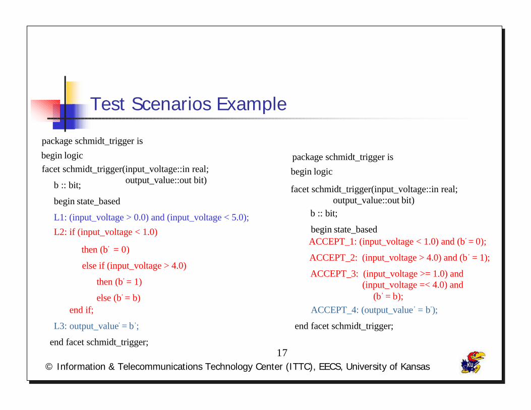
Test Scenarios Example
package schmidt_trigger is
begin logic
facet schmidt_trigger(input_voltage::in real;output_value::out bit)
b :: bit;
begin state_basedACCEPT_1: (input_voltage < 1.0) and (b’ = 0);
ACCEPT_2: (input_voltage > 4.0) and (b’ = 1);
ACCEPT_3: (input_voltage >= 1.0) and (input_voltage =< 4.0) and
(b’ = b);ACCEPT_4: (output_value’ = b’);
end facet schmidt_trigger;
package schmidt_trigger is
begin logicfacet schmidt_trigger(input_voltage::in real; output_value::out bit)
begin state_based
b :: bit;
L1: (input_voltage > 0.0) and (input_voltage < 5.0);
L2: if (input_voltage < 1.0)
then (b’ = 0)
else if (input_voltage > 4.0)
else (b’ = b)
L3: output_value’ = b’;
end facet schmidt_trigger;
then (b’ = 1)
end if;
© Information & Telecommunications Technology Center (ITTC), EECS, University of Kansas18
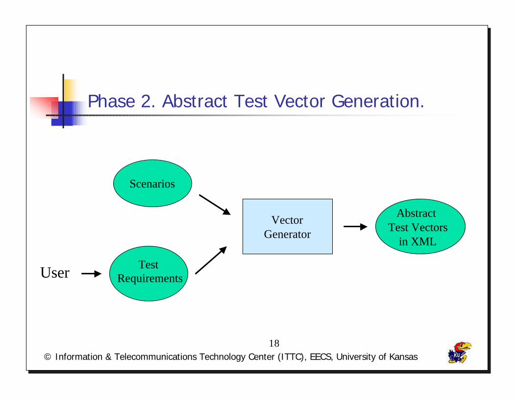
Phase 2. Abstract Test Vector Generation.
Scenarios
User
Abstract Test Vectors
in XML
Test Requirements
VectorGenerator

© Information & Telecommunications Technology Center (ITTC), EECS, University of Kansas19
Test Requirements
• Purpose - Limits number of test cases
• Constraints – Input parameters
• How are they Specified - User
• Classification• General Test Requirements• Initial Vectors and Test Cases

© Information & Telecommunications Technology Center (ITTC), EECS, University of Kansas20
General Test Requirements
• Purpose: Initializes values to input parameters.
• Function Signature:• test_req(var, lower_bound, upper-bound, increment :: number) :: bit
test_req(var1,1,2,1)
test_req(var2,5,10,2)
var1 = 1, var2 = 5
var1 = 1, var2 = 7
var1 = 1, var2 = 9
var1 = 2, var2 = 5
var1 = 2, var2 = 7
var1 = 2, var2 = 9
© Information & Telecommunications Technology Center (ITTC), EECS, University of Kansas21
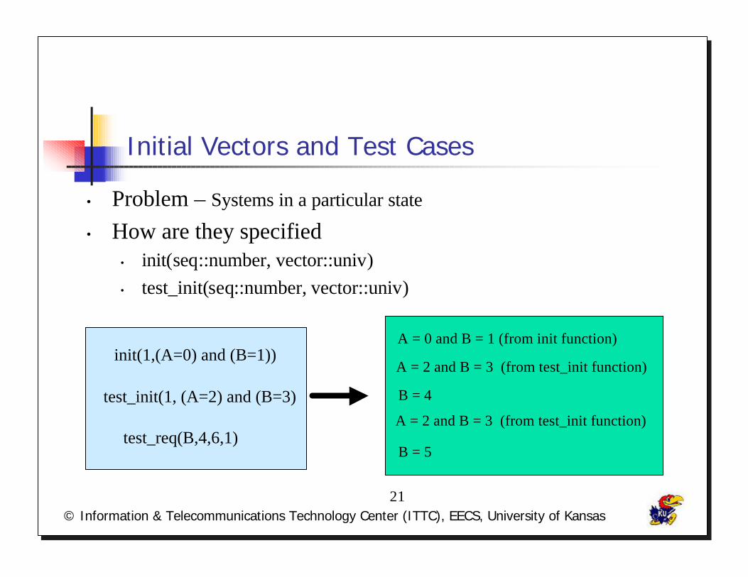
Initial Vectors and Test Cases
• Problem – Systems in a particular state
• How are they specified• init(seq::number, vector::univ)• test_init(seq::number, vector::univ)
init(1,(A=0) and (B=1))
test_init(1, (A=2) and (B=3)
test_req(B,4,6,1)
A = 0 and B = 1 (from init function)
A = 2 and B = 3 (from test_init function)
B = 4
B = 5
A = 2 and B = 3 (from test_init function)
© Information & Telecommunications Technology Center (ITTC), EECS, University of Kansas22
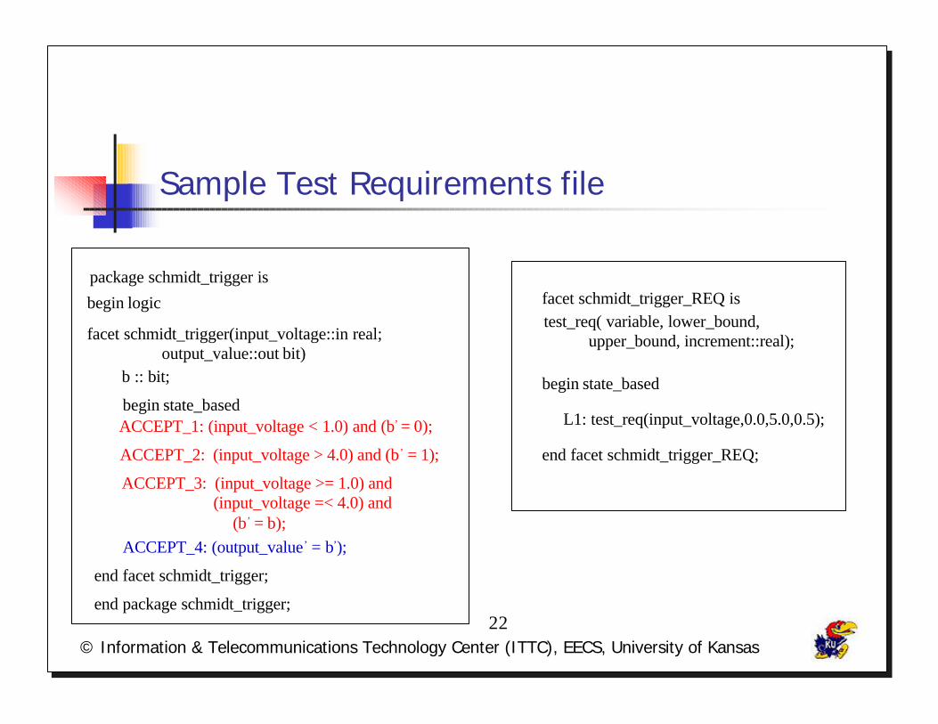
Sample Test Requirements file
package schmidt_trigger is
begin logic
facet schmidt_trigger(input_voltage::in real;output_value::out bit)
b :: bit;
begin state_basedACCEPT_1: (input_voltage < 1.0) and (b’ = 0);
ACCEPT_2: (input_voltage > 4.0) and (b’ = 1);
ACCEPT_3: (input_voltage >= 1.0) and (input_voltage =< 4.0) and
(b’ = b);ACCEPT_4: (output_value’ = b’);
end facet schmidt_trigger;
facet schmidt_trigger_REQ istest_req( variable, lower_bound,
upper_bound, increment::real);
begin state_based
L1: test_req(input_voltage,0.0,5.0,0.5);
end facet schmidt_trigger_REQ;
end package schmidt_trigger;

© Information & Telecommunications Technology Center (ITTC), EECS, University of Kansas23
Abstract Test Vectors in XML
• Contain expected output values for input values• Language independent, simulation environment
independent
<! ELEMENT vectorslist (vector)*>
<! ELEMENT vector (condition)* >
<! ELEMENT condition (parameter, value)*>
<! ELEMENT parameter (#PCDATA)>
<! ELEMENT value (#PCDATA)>
<! ATTLIST parameter mode CDATA #REQUIRED>
© Information & Telecommunications Technology Center (ITTC), EECS, University of Kansas24
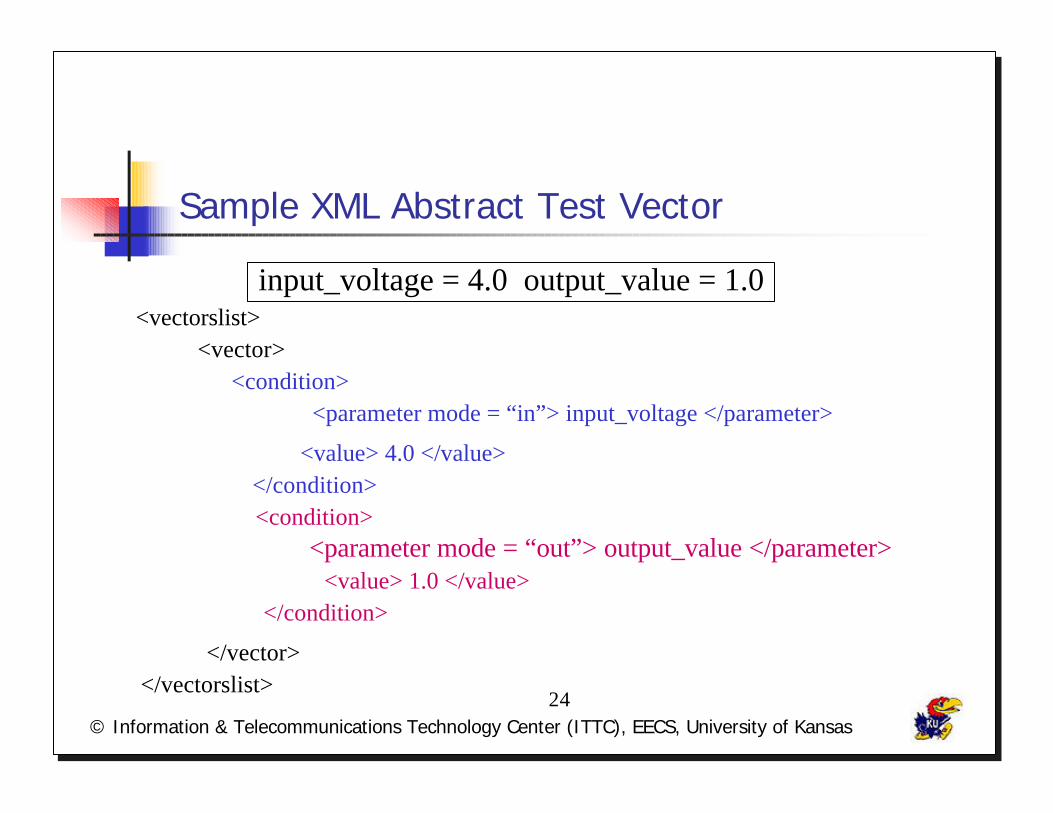
Sample XML Abstract Test Vector
input_voltage = 4.0 output_value = 1.0<vectorslist>
<vector><condition>
<parameter mode = “in”> input_voltage </parameter>
<value> 4.0 </value></condition><condition>
<parameter mode = “out”> output_value </parameter><value> 1.0 </value>
</condition>
</vector></vectorslist>
© Information & Telecommunications Technology Center (ITTC), EECS, University of Kansas25
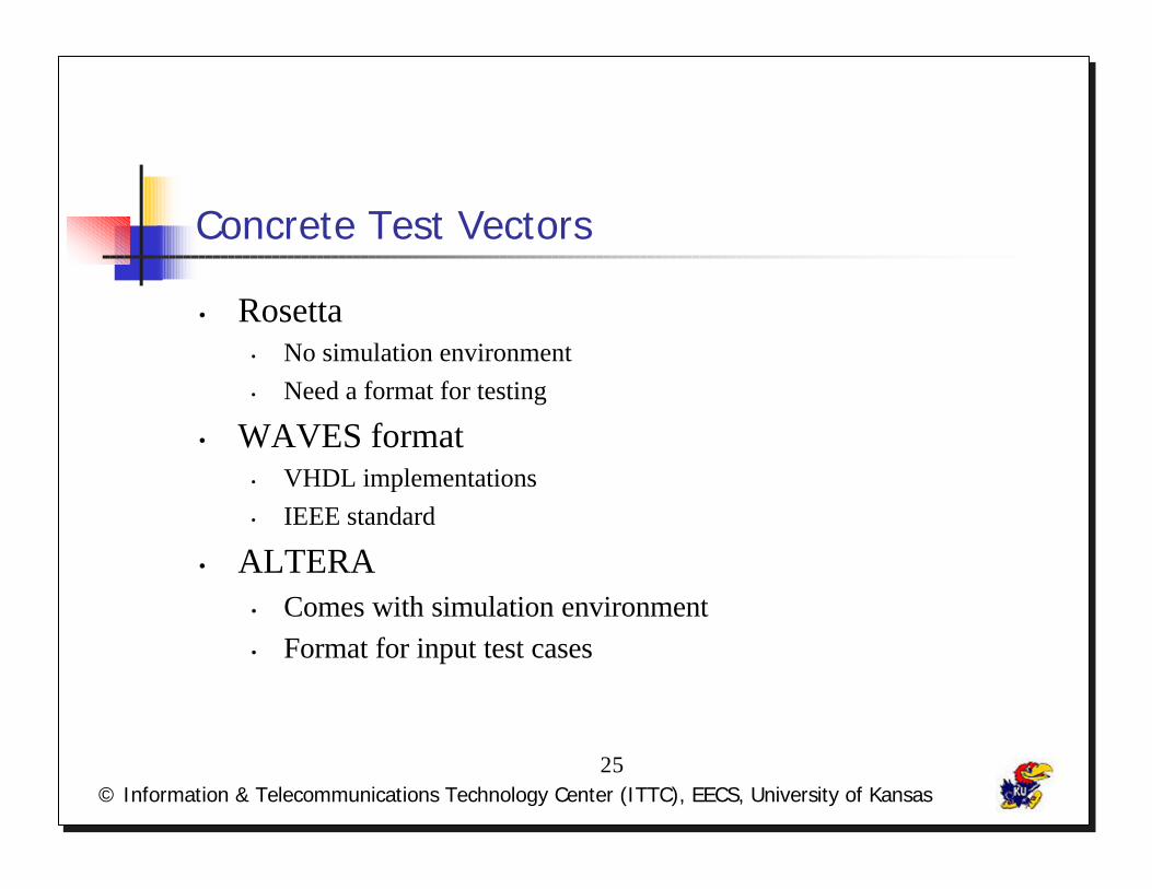
Concrete Test Vectors
• Rosetta• No simulation environment• Need a format for testing
• WAVES format• VHDL implementations• IEEE standard
• ALTERA• Comes with simulation environment• Format for input test cases

© Information & Telecommunications Technology Center (ITTC), EECS, University of Kansas26
Phase 3. Generation of Concrete Test Vectors
Abstract Test Vectorsin XML
XSLT
XML Parser
WAVESformat
Input formatfor ALTERA
modelsApplication
© Information & Telecommunications Technology Center (ITTC), EECS, University of Kansas27
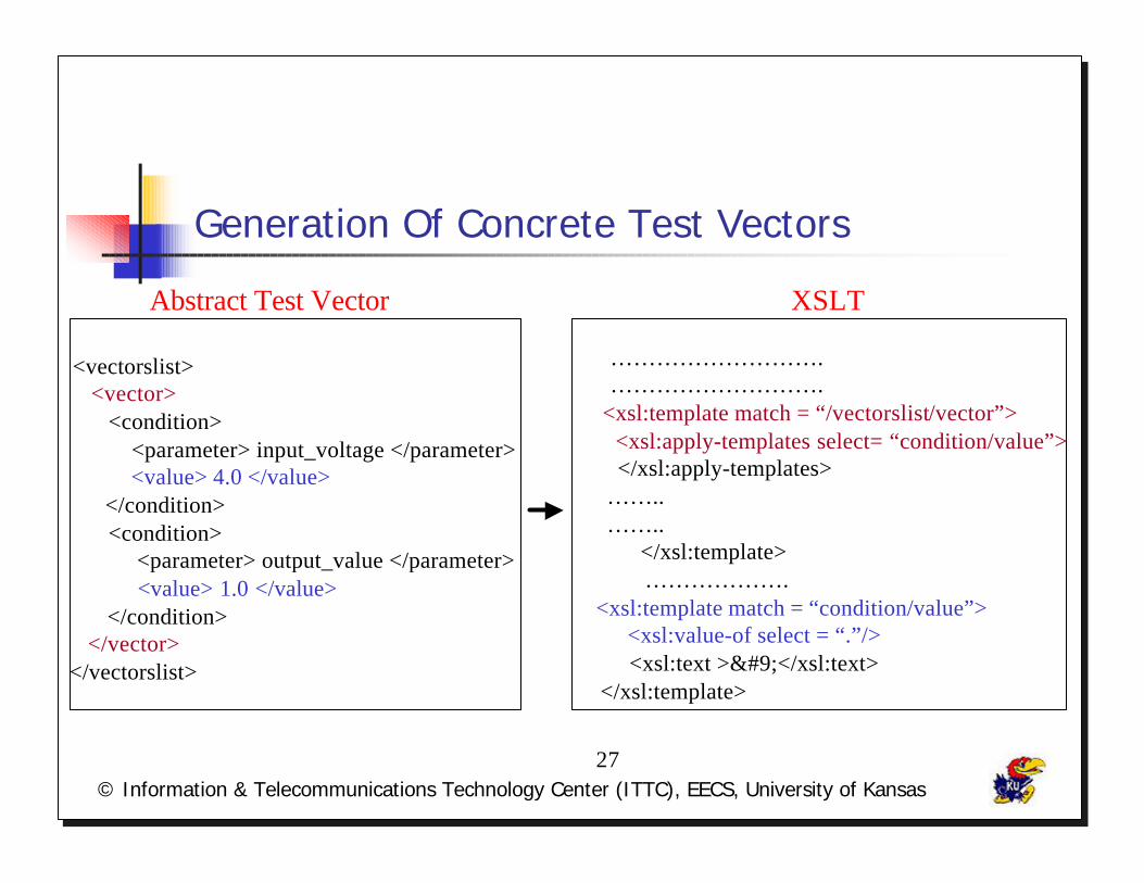
Generation Of Concrete Test Vectors
<vectorslist><vector>
<condition> <parameter> input_voltage </parameter>
<value> 4.0 </value> </condition> <condition>
<parameter> output_value </parameter> <value> 1.0 </value>
</condition></vector>
</vectorslist>
……………………….……………………….
<xsl:template match = “/vectorslist/vector”> <xsl:apply-templates select= “condition/value”>
</xsl:apply-templates> …….. ……..
</xsl:template> ……………….
<xsl:template match = “condition/value”> <xsl:value-of select = “.”/> <xsl:text >	</xsl:text>
</xsl:template>
Abstract Test Vector XSLT
© Information & Telecommunications Technology Center (ITTC), EECS, University of Kansas28
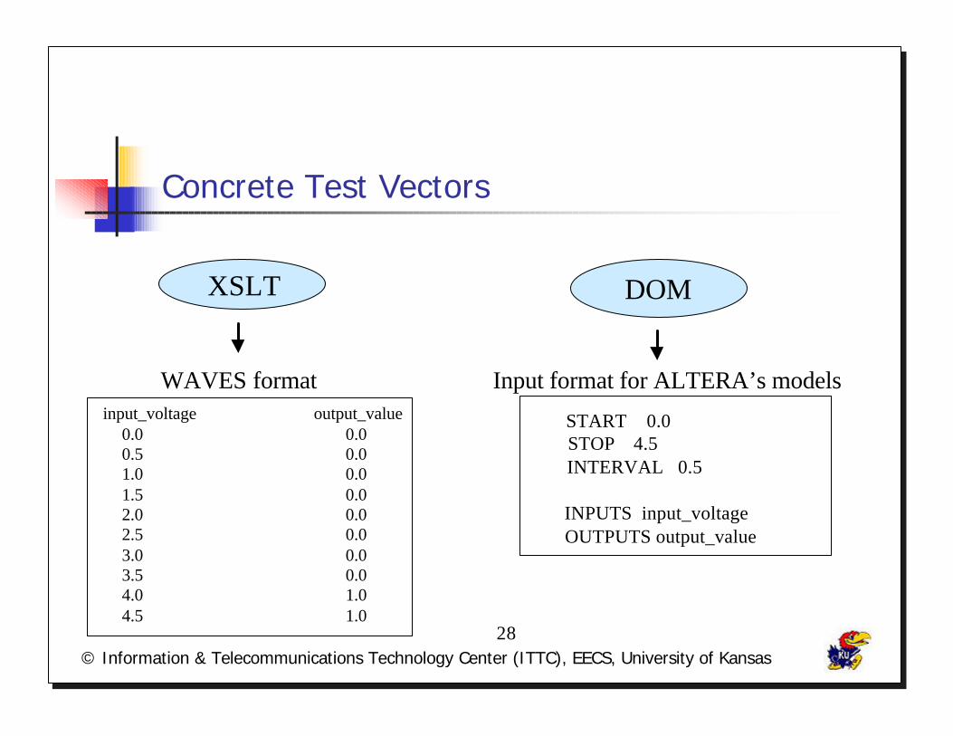
Concrete Test Vectors
input_voltage output_value0.0 0.0 0.5 0.0 1.0 0.0 1.5 0.0 2.0 0.0 2.5 0.0 3.0 0.0 3.5 0.0 4.0 1.0 4.5 1.0
START 0.0STOP 4.5
INTERVAL 0.5
INPUTS input_voltage OUTPUTS output_value
WAVES format Input format for ALTERA’s models
XSLT DOM
© Information & Telecommunications Technology Center (ITTC), EECS, University of Kansas29
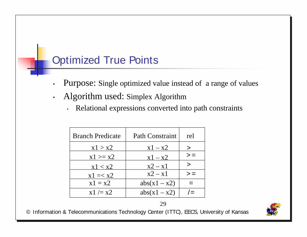
Optimized True Points
• Purpose: Single optimized value instead of a range of values
• Algorithm used: Simplex Algorithm• Relational expressions converted into path constraints
Branch Predicate Path Constraint rel
x1 > x2 x1 – x2 >x1 >= x2 x1 – x2 >=
x2 – x1x1 =< x2 x2 – x1 >=x1 = x2x1 /= x2
abs(x1 – x2)abs(x1 – x2)
=/=
x1 < x2 >

© Information & Telecommunications Technology Center (ITTC), EECS, University of Kansas30
Optimized True Points
Cost Functions for each path constraint
G(gi(x),wi) = exp(-wi(gi(x))-1.0) gi(x) = 0
G(gi(x),wi) = exp(-wi abs(gi(x))) gi(x) /= 0
G(gi(x),wi) = exp(-wi(gi(x))+1.0) gi(x) >= 0
G(gi(x),wi) = exp(-wi(gi(x))) gi(x) > 0
Cost FunctionPath Constraints
R = ∑ G(gi(x), wi)i = 1
n
© Information & Telecommunications Technology Center (ITTC), EECS, University of Kansas31
Testing
• Testing• schmidt – trigger, alarm clock specification• Regression Testing
• Industry Application• Edaptive

© Information & Telecommunications Technology Center (ITTC), EECS, University of Kansas32
Conclusions
• Specification based techniques – More abstraction
• Automatic Test Data Generator – Helpful in Testing
• Framework has been Designed
• Concrete Test Vectors -
WAVES format
Input formatfor simulating
ALTERA MODELS
© Information & Telecommunications Technology Center (ITTC), EECS, University of Kansas33
Future Work
• Support - Structural specifications
• Test Requirements format - XML
• Automated Test Harness – From XML
© Information & Telecommunications Technology Center (ITTC), EECS, University of Kansas34
Acknowledgements…

© Information & Telecommunications Technology Center (ITTC), EECS, University of Kansas35
?’sssss…
© Information & Telecommunications Technology Center (ITTC), EECS, University of Kansas36
?’sssss…