Automatic sliding doors - GEZE · 22.2 Display programme switch DPS ... à Only specialists...
68
Automatic sliding doors DCU1-NT DCU1-2M-NT EN Wiring diagram 160924-01
Transcript of Automatic sliding doors - GEZE · 22.2 Display programme switch DPS ... à Only specialists...
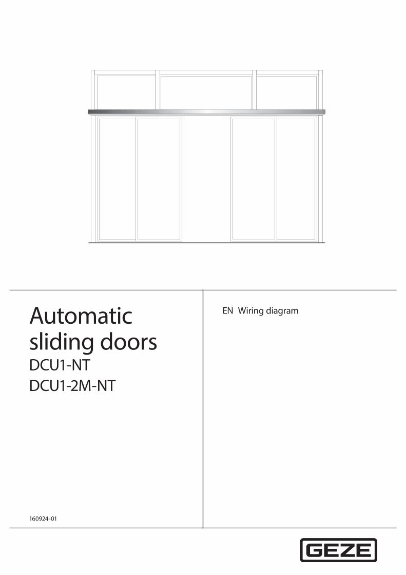
Automatic sliding doorsDCU1-NTDCU1-2M-NT
EN Wiring diagram
160924-01
Automatic sliding doors
2
Contents
Symbols and illustrations ..................................................................................................................................................4
Validity .....................................................................................................................................................................................4
Product liability .....................................................................................................................................................................4
1 Safety notices ............................................................................................................................................................51.1 Important safety instructions ......................................................................................................................................................................51.2 Installation information .................................................................................................................................................................................51.3 Safety-conscious working .............................................................................................................................................................................51.4 Inspection of the installed system .............................................................................................................................................................51.5 Disposal of the door system .........................................................................................................................................................................6
2 Abbreviations ............................................................................................................................................................6
3 Electrical data ............................................................................................................................................................8
4 Safety sensor “close” ...............................................................................................................................................84.1 Active infrared detector and radar movement detector GC 363 R ................................................................................................94.2 Active infrared detector and self-monitored radar movement detector GC 363 SF ........................................................... 104.3 Active infrared detector GC 339 ................................................................................................................................................................114.4 Active infrared detector and radar movement detector GC 365 R ..............................................................................................114.5 Active infrared detector and radar movement detector GC 365 SF ............................................................................................124.6 Active infrared detector GC 341 ................................................................................................................................................................124.7 Active infrared sensor push button AIR 30 ...........................................................................................................................................134.8 1-channel photoelectric barrier GZ 470 V .............................................................................................................................................134.9 2-channel photoelectric barrier GZ 472 V .............................................................................................................................................14
5 Safety sensor “open” ............................................................................................................................................145.1 Active infrared detector GC 339 ................................................................................................................................................................155.2 Active infrared detector GC 341 ............................................................................................................................................................... 165.3 Active infrared sensor push button AIR 30 .......................................................................................................................................... 16
6 Break-out doors ......................................................................................................................................................176.1 Break-out sensor .............................................................................................................................................................................................176.2 Break-out sensor and safety sensor “open” ..........................................................................................................................................17
7 Series connection of safety sensors ............................................................................................................... 207.1 Safety sensor “close” (standard doors) .................................................................................................................................................. 207.2 Safety sensor “close” (FR doors) ............................................................................................................................................................... 237.3 Protecting the sensor cable against short-circuit ............................................................................................................................. 26
8 Mechanical contact .............................................................................................................................................. 278.1 Key switch ......................................................................................................................................................................................................... 278.2 Emergency shut-off switch without illumination .............................................................................................................................. 278.3 Emergency shut-off switch with illumination ..................................................................................................................................... 27
9 Contact sensor inside .......................................................................................................................................... 289.1 Standard doors ............................................................................................................................................................................................... 289.2 Doors on rescue routes ............................................................................................................................................................................... 29
10 Contact sensor outside ....................................................................................................................................... 3010.1 GC 302 R radar movement detector ....................................................................................................................................................... 3010.2 Active infrared detector and radar movement detector GC 363 R ............................................................................................. 3010.3 Active infrared fan-shaped sensor and radar movement detector GC 365 R ......................................................................... 3010.4 Push button (potential-free contact) ..................................................................................................................................................... 30
Automatic sliding doors
3
11 Configurable inputs ............................................................................................................................................. 3011.1 Switch function .............................................................................................................................................................................................. 3011.2 Wireless activation .........................................................................................................................................................................................3111.3 Pharmacy opening .........................................................................................................................................................................................3111.4 Emergency lock .............................................................................................................................................................................................. 3211.5 Stop ..................................................................................................................................................................................................................... 32
12 WC control............................................................................................................................................................... 33
13 Interlocking door system, vestibule ............................................................................................................... 35
14 Mode of operation ............................................................................................................................................... 3514.1 Mechanical programme switch................................................................................................................................................................ 3614.2 Switching the operating mode using push buttons or switches ................................................................................................ 3614.3 Keypad programme switch ....................................................................................................................................................................... 3714.4 Display programme switch (DPS) with OFF switch ........................................................................................................................... 3714.5 Reset function (DPS with OFF switch, TPS) .......................................................................................................................................... 3814.6 Blocking or releasing operation of TPS and DPS ............................................................................................................................... 38
15 Configurable outputs .......................................................................................................................................... 3915.1 PA1 (gong) ........................................................................................................................................................................................................ 3915.2 PA2 (fault, fan) ................................................................................................................................................................................................. 39
16 Mains connection ................................................................................................................................................. 40
17 Locking mechanism ..............................................................................................................................................4117.1 Tooth belt locking ..........................................................................................................................................................................................4117.2 Rod locking, electromechanical break axle ..........................................................................................................................................4117.3 Hook bolt Lock A............................................................................................................................................................................................ 42
18 Rechargeable battery .......................................................................................................................................... 42
19 Motor gear unit ..................................................................................................................................................... 43
20 Control ...................................................................................................................................................................... 44
21 Commissioning and service .............................................................................................................................. 4521.1 Production test ............................................................................................................................................................................................... 4521.2 Commissioning ............................................................................................................................................................................................... 4521.3 Service ............................................................................................................................................................................................................... 48
22 Service menu ......................................................................................................................................................... 4922.1 Service terminal ST220 ................................................................................................................................................................................ 4922.2 Display programme switch DPS ............................................................................................................................................................... 59
23 Fault messages ...................................................................................................................................................... 6623.1 Display programme switch/Service terminal ST220 ........................................................................................................................ 6623.2 Keypad programme switch ....................................................................................................................................................................... 67
Automatic sliding doors
4
Symbols and illustrations
Warning noticesWarning notices are used in these instructions to warn you of property damage and personal injury.
X Always read and observe these warning notices. X Observe all measures marked with the warning symbol and warning word .
Warning symbol
Warning word Meaning
DANGER Danger to persons. Non-compliance will result in death or serious injuries.
WARNING Danger to persons. Non-compliance may result in death or serious injuries.
CAUTION Danger to persons. Non-compliance can result in minor injuries.
More symbols and illustrationsImportant information and technical notes are highlighted to explain correct operation.
Symbol Meaning
means “important information”; Information on avoiding material damage, understanding a concept or optimising the operation sequences
means “additional Information”
X Symbol for an action: This means you have to do something.
X If there are several actions to be taken, keep to the given order.
Escape and rescue route Symbol in a table or for a piece of information only applicable to escape and rescue route doors.
Not an escape and rescue route Symbol in a table or relating to information which applies to standard doors without an escape and rescue route function.
Conforms to DIN 18650/EN 16005
Symbol in a table or relating to information on safety sensors that are standard-compliant.
Does not conform to DIN 18650 / EN 16005
Symbol in a table or relating to information on safety sensors that are not standard-compliant.
ValidityValid for devices from à Hardware: DCU1-NT Rev. A0, DCU1-2M-NT Rev. A0 à Software: DCU1-NT from V5.0, DCU1-2M-NT from V5.0
Product liabilityIn accordance with the liability of the manufacturer for his products as defined in the German “Product Liability Act”, the information contained in this brochure (product information and proper use, misuse, product performance, product maintenance, obligations to provide information and instructions) is to be observed. Failure to comply releases the manufacturer from his statutory liability.
Automatic sliding doors
5
Safety notices
1 Safety notices
1.1 Important safety instructionsIt is important to follow these instructions for the safety of persons.These instructions must be kept. à Only specialists authorised by GEZE are permitted to carry out installation, commissioning and maintenance work. à Unauthorised modifications to the system release GEZE from liability for any resulting damages. à GEZE does not accept any warranty for combinations with third-party products. In addition, only original GEZE
parts may be used for repair and maintenance work. à Connection to the mains voltage must be carried out by a qualified electrician. Perform the power connection
and equipment earth conductor test in accordance with VDE 0100 Part 610. à Use an on-site 10-A overload cut-out as the line-side disconnecting device. à Attach safety stickers to glass door leaves, mat. no. 081476. à In accordance with Machinery Directive 2006/42/EC, a safety analysis
is to be performed and the door system identified in accordance with CE Identification Directive 93/68/EEC before the door system is commissioned.
à Observe the latest versions of directives, standards and country-specific regulations, in particular: à AutSchR “Guidelines on automatic sliding doors in escape and rescue routes” à EN 16005 “Power operated pedestrian doorsets – Safety in use – Requirements and test methods” à DIN 18650, Part 1 and Part 2 “Automatic door systems” à DIN VDE 100-600 “Installation of low-voltage systems - Part 6 Tests” à DIN EN 60335-2-103 “Household and similar electrical appliances - Safety; Particular requirements for drives
for gates, doors and windows” à Accident Prevention Regulations, in particular BGV A1 (VBG1) “General Regulations” and BGV A3 (VBG4)
“Electrical Installations and Resources” à ASR A1.7 “Directives for doors and gates”
1.2 Installation information à The drive is designed exclusively for use in dry rooms. X Use only the cables specified on the cable plan provided. Cables must be shielded in compliance with the
wiring diagram. X Always use insulated wire-end ferrules for wire cores. X Insulate wires that are not used. X Secure loose, internal drive cables with cable ties. X Observe the maximum permitted overall current drain required to supply the periphery.
1.3 Safety-conscious working X Secure the workplace against unauthorised entry. X Pay attention to the swivelling range of long system parts. X Secure the cover/drive shrouding against falling. X Before working on the electrical system, disconnect the power supply (mains and rechargeable battery) and
check that no voltage is present. Note that if an uninterruptible power supply (UPS) is used, the system will still be supplied with power despite the fact that the power supply is disconnected.
à Risk of injury by moving parts (drawing in of hair, clothing, ...) when a drive is opened. à Danger of injury caused by unsecured crushing, impact, drawing-in or shearing spots. à Danger of injury due to sharp edges in the drive. à Danger of injury due to glass breakage.
1.4 Inspection of the installed system X Measures for checking safety and prevention of crushing, impact, shearing or drawing-in spots. X Check the function of the presence sensors and movement detectors.
à The detection area of the movement detector in the direction of emergency exit must cover the opening width (ÖW) × 1.5 m in front of the door.
X Check the protective earth connection to all metal parts that can be touched.
Automatic sliding doors
6
Abbreviations
1.5 Disposal of the door system à The door system is made up of materials that should be sent for recycling.
For this purpose, the individual components should be sorted corresponding to material type: à Aluminium (profiles, cover, deflection pulleys, sliding blocks, ...) à Iron (drivers, screws, ...) à Plastic à Electronic components (dead bolt, motor gear unit, control, transformer, sensors, ...) à Cables à Rechargeable battery
X The parts listed should be handed in to communal collection points or be disposed of via a scrap recycling company
à Rechargeable batteries and batteries contain pollutants and heavy metals. X Rechargeable batteries and waste batteries should be handed in to communal collection points or retailers.
à The rechargeable battery for the drive is a plug-in type and connected to the control; it can be removed easily by loosening two fixing screws.
Information regarding the German Battery Directive:(Applicable in Germany and in all other member states of the European Union as well as in other European coun-tries, together with the countries' own provisions for a separate waste battery collection system.) In accordance with the German Battery Directive, we are obliged to inform you of the following in connection with the sale of batteries or rechargeable batteries respectively in connection with the delivery of devices con-taining batteries or rechargeable batteries: Rechargeable batteries and batteries must not be disposed of with household waste. Disposal with household waste is expressly forbidden according to the German Battery Direc-tive. As the final consumer, you are bound by law to return waste batteries and rechargeable batteries. Please return waste batteries and rechargeable batteries to a communal collection point or retailer. Following use, you may return any batteries or rechargeable batteries received from us by post. The address is: GEZE GmbH, Incoming Goods, Reinhold-Vöster-Str. 21-29, 71229 Leonberg/Germany.
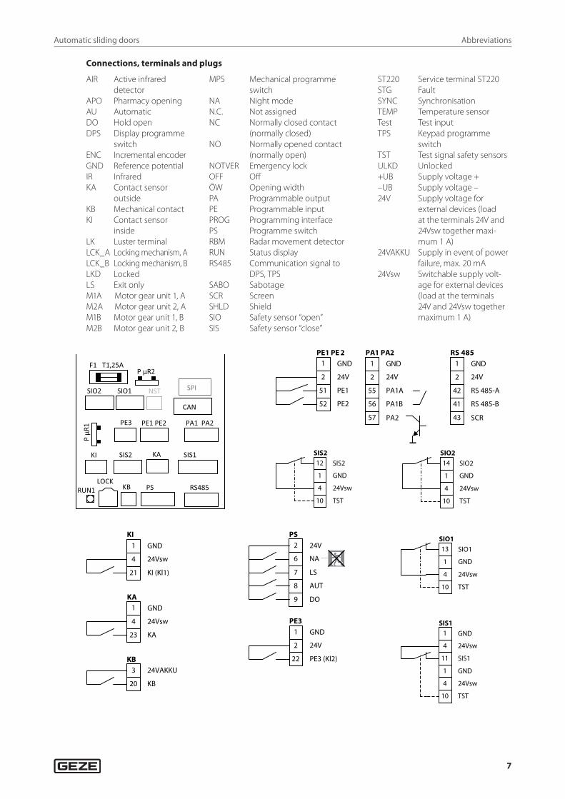
2 Abbreviations
Wire colours
BN brownBK blackBU blue
GN greenGY greyYE yellow
OG orangeP-K pinkRD red
TQ turquoiseVT violetWH white
Automatic sliding doors
7
Abbreviations
Connections, terminals and plugs
AIR Active infrared detector
APO Pharmacy openingAU AutomaticDO Hold openDPS Display programme
switch ENC Incremental encoderGND Reference potentialIR InfraredKA Contact sensor
outsideKB Mechanical contactKI Contact sensor
insideLK Luster terminalLCK_A Locking mechanism, ALCK_B Locking mechanism, BLKD LockedLS Exit onlyM1A Motor gear unit 1, AM2A Motor gear unit 2, AM1B Motor gear unit 1, BM2B Motor gear unit 2, B
MPS Mechanical programme switch
NA Night modeN.C. Not assignedNC Normally closed contact
(normally closed)NO Normally opened contact
(normally open)NOTVER Emergency lockOFF OffÖW Opening widthPA Programmable outputPE Programmable inputPROG Programming interfacePS Programme switchRBM Radar movement detectorRUN Status displayRS485 Communication signal to
DPS, TPSSABO SabotageSCR ScreenSHLD Shield SIO Safety sensor “open”SIS Safety sensor “close”
ST220 Service terminal ST220STG FaultSYNC SynchronisationTEMP Temperature sensorTest Test inputTPS Keypad programme
switchTST Test signal safety sensorsULKD Unlocked+UB Supply voltage +–UB Supply voltage –24V Supply voltage for
external devices (load at the terminals 24V and 24Vsw together maxi-mum 1 A)
24VAKKU Supply in event of power failure, max. 20 mA
24Vsw Switchable supply volt-age for external devices (load at the terminals 24V and 24Vsw together maximum 1 A)
KI KA SIS2
PS KB RS485 LOCK
PE1 PE2 PE3 PA1 PA2
RUN1
P µR
1
SIO1 SIO2
F1 T1,25A P µR2
CAN
SIS1
SPI NST
GND1
2 24V
51 PE1
52 PE2
PE1 PE 2
PA1A
PA1B
GND1
2 24V
55
56
PA1 PA2
PA257
RS 485-A
RS 485-B
GND1
2 24V
42
41
RS 485
SCR43
SIS212
1 GND
4 24Vsw
10 TST
SIS2
SIO214
1 GND
4 24Vsw
10 TST
SIO2
GND1
4 24Vsw
21 KI (Kl1)
KI
GND1
4 24Vsw
23 KA
KA
3 24VAKKU
20 KB
KB
24V2
6 NA
7 LS
8 AUT
PS
DO9
GND1
2 24V
22 PE3 (Kl2)
PE3
SIO113
1 GND
4 24Vsw
10 TST
SIO1
GND1
4 24Vsw
11 SIS1
1 GND
4 24Vsw
10 TST
SIS1
Automatic sliding doors
8
Electrical data
3 Electrical dataMains connection 230 V
à Mains voltage 230 V AC –15 %, + 10 %
à Frequency 50 Hz
Mains connection 110 V
à Mains voltage 110 V AC –10 %, + 10 %
à Frequency 60 Hz
Slimdrive and ECdrive variants
à Capacity rating 140 W
à Primary fuse 2 A slow-blow, 5 x 20 mm
Powerdrive variants
à Capacity rating 200 W
à Primary fuse 2.5 A slow-blow, 5 x 20 mm
General electrical data
à Protection rating I
à Mains connection Fixed connection (installation cable)
à Secondary voltage (transformer) 33 V AC (46 V DC)
à Control voltage for external components 24 V DC ±10 %
à Output current control voltage 1 A
à Fuse protection <24 V 1.25 A slow-blow, 5 x 20 mm
à Temperature range –15 °C ... +50 °C
à IP rating IP20
4 Safety sensor “close” à Up to four safety sensors “close” can be connected (terminals SIS1, SIS2, SIO1 and SIO2). à During detection, the output of the safety sensor “close” is open. GND is applied to the input. à Set the contact type for the terminal used:
à With DPS: s1 , s2, s3 or s4 to o2
à With ST220: “SI1”, “SI2”, “SI3” or “SI4 contact type” to “normally closed contact” à Set the function for detection (see section 22.1.4 Service menu ST220 and section 22.2.2 Service menu DPS):
à With DPS: f1 , f2, f3 or f4 à With ST220: “SI1”, “SI2”, “SI3” or “SI4 function”
à Check function and correct setting of the sensors during commissioning and service.
Automatic sliding doors
9
Safety sensor “close”
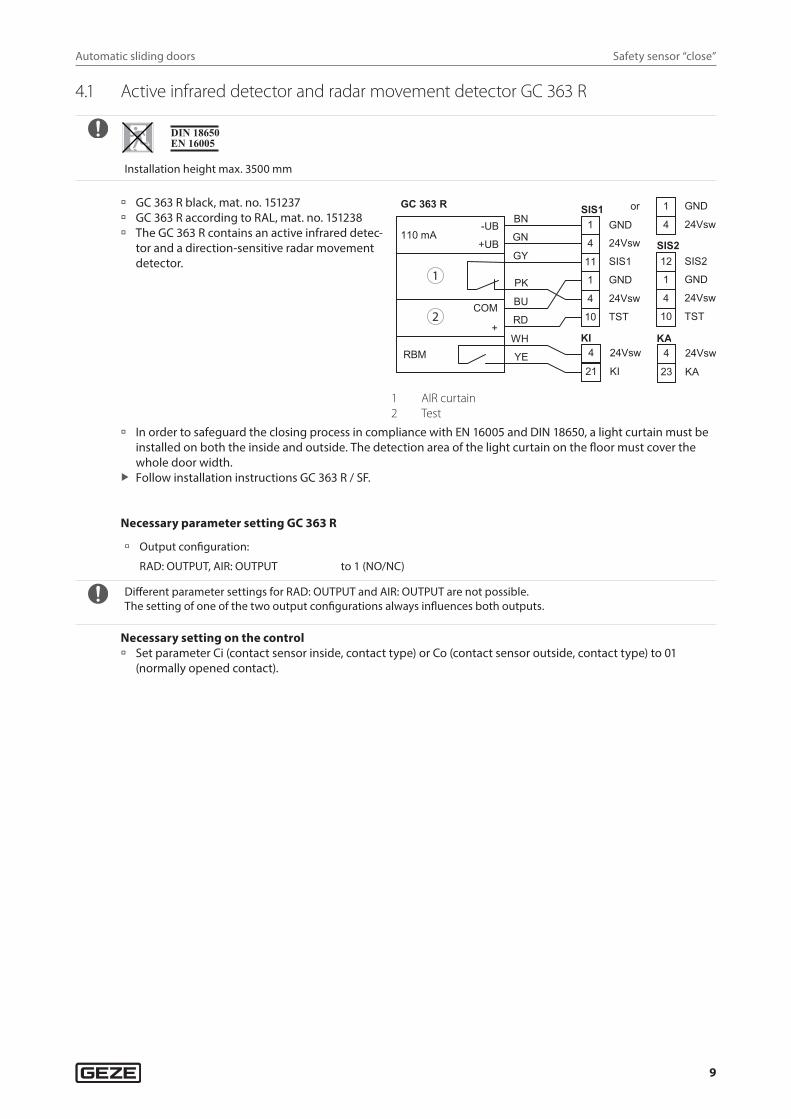
4.1 Active infrared detector and radar movement detector GC 363 R
Installation height max. 3500 mm
à GC 363 R black, mat. no. 151237 à GC 363 R according to RAL, mat. no. 151238 à The GC 363 R contains an active infrared detec-
tor and a direction-sensitive radar movement detector.
GND1
4 24Vsw
11 SIS1
1 GND
4 24Vsw
10 TST
SIS1 1 GND
4 24Vsw
1 GND
4 24Vsw
10 TST
12 SIS2
or
4 24Vsw
21 KI
KI4 24Vsw
23 KA
KA
110 mA
RBM
GC 363 R
-UB
+UB
COM
+
BN
GN
GY
PK
BU
RD
WH
YE
SIS2
1
2
1 AIR curtain2 Test
à In order to safeguard the closing process in compliance with EN 16005 and DIN 18650, a light curtain must be installed on both the inside and outside. The detection area of the light curtain on the floor must cover the whole door width.
X Follow installation instructions GC 363 R / SF.
Necessary parameter setting GC 363 R
à Output configuration:
RAD: OUTPUT, AIR: OUTPUT to 1 (NO/NC)
Different parameter settings for RAD: OUTPUT and AIR: OUTPUT are not possible.The setting of one of the two output configurations always influences both outputs.
Necessary setting on the control à Set parameter Ci (contact sensor inside, contact type) or Co (contact sensor outside, contact type) to 01
(normally opened contact).
Automatic sliding doors
10
Safety sensor “close”
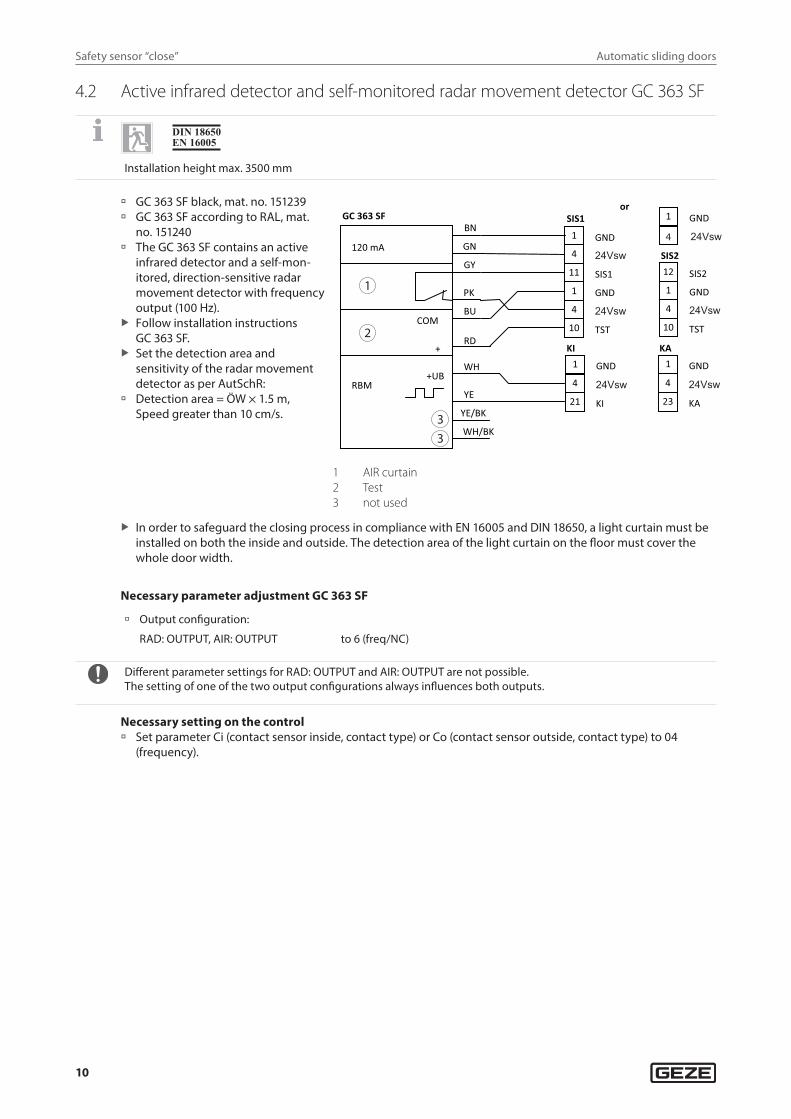
4.2 Active infrared detector and self-monitored radar movement detector GC 363 SF
Installation height max. 3500 mm
à GC 363 SF black, mat. no. 151239 à GC 363 SF according to RAL, mat.
no. 151240 à The GC 363 SF contains an active
infrared detector and a self-mon-itored, direction-sensitive radar movement detector with frequency output (100 Hz).
X Follow installation instructions GC 363 SF.
X Set the detection area and sensitivity of the radar movement detector as per AutSchR:
à Detection area = ÖW × 1.5 m, Speed greater than 10 cm/s.
1
2
33
4 24Vsw
21 KI
KI
COM
+
BN
GN
GY
PK
BU
RD
WH
YE RBM
WH/BK
120 mA
GC 363 SF
YE/BK
1 GND
+UB
1 GND
SIS2
1 GND 4 24Vsw
10 TST
12 SIS2
or
GND 1
4 24Vsw
11 SIS1 1 GND
4 24Vsw 10 TST
SIS1
4 24Vsw
23 KA
KA 1 GND
4 24Vsw
1 AIR curtain2 Test3 not used
X In order to safeguard the closing process in compliance with EN 16005 and DIN 18650, a light curtain must be installed on both the inside and outside. The detection area of the light curtain on the floor must cover the whole door width.
Necessary parameter adjustment GC 363 SF
à Output configuration:
RAD: OUTPUT, AIR: OUTPUT to 6 (freq/NC)
Different parameter settings for RAD: OUTPUT and AIR: OUTPUT are not possible.The setting of one of the two output configurations always influences both outputs.
Necessary setting on the control à Set parameter Ci (contact sensor inside, conta ct type) or Co (contact sensor outside, contact type) to 04
(frequency).
Automatic sliding doors
11
Safety sensor “close”
4.3 Active infrared detector GC 339
à GC 339 black, mat. no. 151251 à GC 339 according to RAL, mat. no.
151252 X Follow installation instructions
GC 339. X Insulate unused wires (WH, YE). 1
2
COM
+
BN
GN
GY
PK
BU
RD
WH
YE
110 mA
GC 339 1 GND
SIS2
1 GND
4 24Vsw
10 TST
12 SIS2
or
GND 1
4 24Vsw
11 SIS1 1 GND
4 24Vsw
10 TST
SIS1
4 24 Vsw
1 AIR curtain2 Test
Necessary parameter setting GC 339
à Output configuration:
AIR: OUTPUT to 1 (NO/NC)
4.4 Active infrared detector and radar movement detector GC 365 R
à GC 365 R, combined detector, black, mat. no. 160283
-UB
+UB
C OM
+
100 mA
GC 365 R B N
WH
B U
P K
B K
R D
GN
Y E
G ND1
4 24Vsw
11 S IS 1
1 G ND
4 24Vsw
10 T S T
S IS 1 1 G ND
4 24Vsw
S IS 2
1 G ND
4 24Vsw
10 T S T
12 S IS 2
1 GND
4 24Vsw
K I1 GND
24Vsw
K A
or
1
2
3
21 K I 23 K A
4
1 AIR curtain2 Test3 Radar movement detector
Parameter setting on the control X Set Ci (contact sensor inside, contact type) or Co (contact sensor outside, contact type) to 01 (normally opened
contact).
X Follow installation instructions GC 365 R / SF.
Automatic sliding doors
12
Safety sensor “close”
4.5 Active infrared detector and radar movement detector GC 365 SF
à GC 365 SF black, combined detector mat. no. 160284
G ND1
4 24Vsw
11 S IS 1
1 G ND
4 24Vsw
10 T S T
S IS 1 1 G ND
4 24Vsw
S IS 2
1 G ND
4 24Vsw
10 T S T
12 S IS 2
1 GND
4 24Vsw
K I
-UB
+UB
C OM
+
100 mA
B N
WH
BU
P K
B K
R D
GN
YE
GC 365 S F or
1
2
21 KI
31 GND
4 24Vsw
K A
23 KA
+UB
1 AIR curtain2 Test3 Radar movement detector
Parameter setting on the control X Set Ci (contact sensor inside, contact type) or Co (contact sensor outside, contact type) to 04 (frequency).
X Follow installation instructions GC 365 R / SF.
4.6 Active infrared detector GC 341
à GC 341 light curtain, black, mat. no. 160285
1
4
GND
11
24Vsw
1
TST
S IS 1
S IS 2
1 G ND
4 24Vsw
10 T S T
12 S IS 2
B N
WH
P K
B U
R D
80 mA
GC 341
C OM
or
1
2 +
B K 4
10
S IS 1
24Vsw
GND
1 G ND
4 24Vsw
1 AIR curtain2 Test
X Follow installation instructions GC 341.
Automatic sliding doors
13
Safety sensor “close”
4.7 Active infrared sensor push button AIR 30
Installation height max. 2500 mm
à AIR 30, mat. no. 072393 à Relay with free swing
diode, mat. no. 103352
12
11
A2
A1
G ND1
4 24Vsw
11 S IS 1
1 G ND
4 24Vsw
10 T S T
S IS 1 1 G ND
4 24Vsw
S IS 2
1 G ND
4 24Vsw
10 T S T
12 S IS 2
100 mA -UB
+UB
1
2
3
4
5
W H
B N
G N
Y E
G Y
AIR 30 or
1
2
1 Test2 Relay with free swing diode
Illustration: with operating voltage switched off
à Follow the installation instructions. à Only use the AIR 30 as an additional sensor for monitoring closing. An AIR 30 sensor alone is not sufficient to
meet the requirements as per DIN 18650. à Set the light/dark selector switch to (D) (setting dark-switching) X Adjust the sensing width to 0.2 m above the floor using the adjustment screw.
4.8 1-channel photoelectric barrier GZ 470 V
GZ 470 V, mat. no. 112726
à Installation 1.0 m above the floor. à Current consumption GZ 470 V: 50 mA
S ender G Z470 V
G Z470 V E mpfänge r
G Y
B K
R D
B K
B N
G N
W H
B N
G N
1
4 24Vsw
11 S IS 1
1 G ND
4 24Vsw
10 T S T
S IS 1
G ND
1 G ND
4 24Vsw
1 G ND
4 24Vsw
10 T S T
S IS 2
12 S IS 2
or
W H
nicht belegt N.C.
1
3
2
1 GZ 470 V receiver2 max. 5 m3 GZ 470 V transmitter
The side distance between the light barrier axis and the sliding panel level must not exceed 5 cm.
Automatic sliding doors
14
Safety sensor “open”
4.9 2-channel photoelectric barrier GZ 472 V
According to DIN 18650 safeguarding with photoelectric barriers is not suitable for people in need of special protection.
X Note and follow other standard-related requirements such as power limitation etc.
GZ 472 V, mat. no. 112727
1 GZ 472 ES V transmitter2 GZ 472 ES V receiver3 max. 5 m4 GZ 472 SE V transmitter5 GZ 472 SE V receiver
W H
B K
G ND1
4 24Vsw
11 S IS 1
1 G ND
4 24Vsw
10 T S T
S IS 1
G Y B N
G N
W H
B N
G N
B KB K
R DG Y
R D
B K
1 G ND
4 24Vsw
1 G ND
4 24Vsw
10 T S T
S IS 2
12 S IS 2
or
1
3
4 5
2
à Installation 0.2 m and 1.0 m above the floor respectively. à Current consumption GZ 472 V: 70 mA
The side distance between the light barrier axis and the sliding panel level must not exceed 5 cm.
5 Safety sensor “open”Check function and correct setting of the sensors during commissioning and service.
à Up to four safety sensors “open” can be connected (terminals SIO1, SIO2, SIS1 and SIS2). à During detection, the output of the safety sensor “open” is open. GND is applied to input SIO1 or SIO2. X Set contact type for terminals used:
à With DPS: Set s3 , s4 , s1 or s2 to o2. à ST220: Set parameter “SI3”, “SI4”, “SI1” or “SI2 contact type” to “open”.
X Set function for terminals used (see section 22.1.4 Service menu ST220 and section 22.2.2 Service menu DPS): à Set DPS parameter f3 , f4 , f1 or f2. à Set ST220 parameter “SI3”, “SI4”, “2SI1“ or “SI2 function”.
For doors in rescue routes: If the safety sensor “open” is activated during opening, the door does not stop until the reduced opening width is reached. The reduced opening width must be larger than or the same size as the required escape route width (official building approval).
Automatic sliding doors
15
Safety sensor “open”
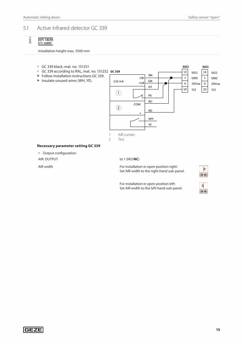
5.1 Active infrared detector GC 339
Installation height max. 3500 mm
à GC 339 black, mat. no. 151251 à GC 339 according to RAL, mat. no. 151252 X Follow installation instructions GC 339. X Insulate unused wires (WH, YE).
1
2
COM
+
BN
GN
GY
PK
BU
RD
WH
YE
110 mA
GC 339 SIO1 13
1
24Vsw4
GND
10 TST
SIO1
-UB+UB
SIO2 14
1
24Vsw4
GND
10 TST
SIO1
1 AIR curtain2 Test
Necessary parameter setting GC 339
à Output configuration:
AIR: OUTPUT to 1 (NO/NC)
AIR width For installation in open position right:Set AIR width to the right-hand sub-panel.
For installation in open position left: Set AIR width to the left-hand sub-panel.
Automatic sliding doors
16
Safety sensor “open”
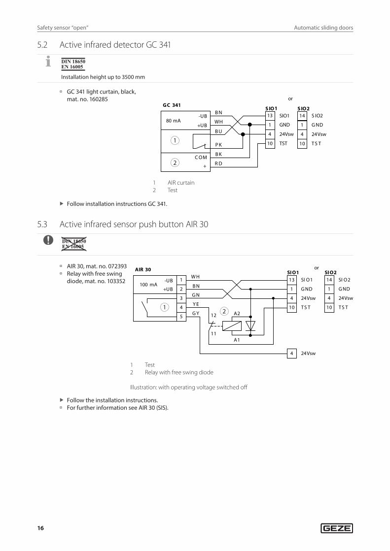
5.2 Active infrared detector GC 341
Installation height up to 3500 mm
à GC 341 light curtain, black, mat. no. 160285
SIO1 13
1 GND
4 24Vsw
10 TST
S IO1 S IO2
1 G ND
4 24Vsw
10 T S T
14 S IO2B N
WH
P K
B U
R D
80 mA
GC 341
-UB
+UB
C OM
or
1
2 +
B K
1 AIR curtain2 Test
X Follow installation instructions GC 341.
5.3 Active infrared sensor push button AIR 30
à AIR 30, mat. no. 072393 à Relay with free swing
diode, mat. no. 103352
100 mA -UB
+UB
1
2
3
4
5
W H
B N
G N
Y E
G Y
AIR 30
13 SI O1
1 G ND
4 24Vsw
10 T S T
SI O1 SI O2
1 G ND
4 24Vsw
10 T S T
14 SI O2
4 24Vsw
12
11
A2
A1
or
12
1 Test2 Relay with free swing diode
Illustration: with operating voltage switched off
X Follow the installation instructions. à For further information see AIR 30 (SIS).
Automatic sliding doors
17
Break-out doors
6 Break-out doors X Before commissioning, set the drive type in the Service menu “Door parameters” “Drive type” (Slim-
drive SL BO, ECdrive BO or TSA 360NT BO). X Note the contents of the “Guidelines on automatic sliding doors in escape and rescue routes (AutSchR)”:
à The programme switch must be protected from unauthorised access e.g. by installing a key switch to block the programme switch.
à The functions emergency lock, interlocking door system and vestibule are not permitted with automatic sliding doors on rescue routes.
à The operating mode setting “night mode” with timer or switch is not possible. à The function “pharmacy” is not available as a configurable input.
à Break-out sensor, mat. no. 076114 à The break-out sensors monitor the position of the swing leaves. They are connected to the inputs SIO1 or SIO2
together with any safety sensors “open” that are available. à When the break-out sensor is triggered, the door stops during opening and closing. à Break-out sensors
à SIO1 is configured automatically. à If used, SIO2 must be configured to contact type “normally closed contact” and function “break-out”.
à When the side panel has been swung out, the break-out sensor output is open. GND is applied to input SIO1 or SIO2.
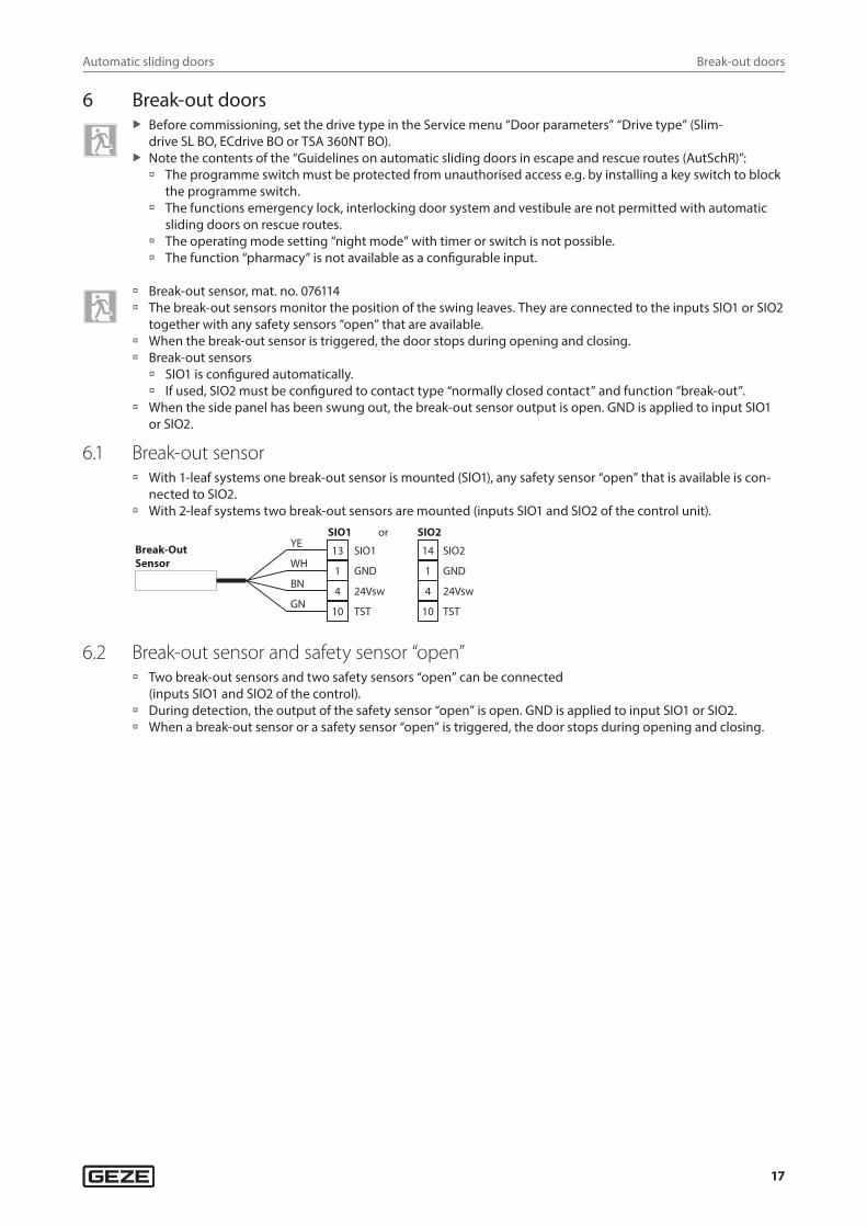
6.1 Break-out sensor à With 1-leaf systems one break-out sensor is mounted (SIO1), any safety sensor “open” that is available is con-
nected to SIO2. à With 2-leaf systems two break-out sensors are mounted (inputs SIO1 and SIO2 of the control unit).
Break-OutSensor
SIO1 SIO2YE
WH
GN
BN
13
1
10
4
14
1
10
4
SIO1
or
GND
TST
24Vsw
SIO2
GND
TST
24Vsw
6.2 Break-out sensor and safety sensor “open” à Two break-out sensors and two safety sensors “open” can be connected
(inputs SIO1 and SIO2 of the control). à During detection, the output of the safety sensor “open” is open. GND is applied to input SIO1 or SIO2. à When a break-out sensor or a safety sensor “open” is triggered, the door stops during opening and closing.
Automatic sliding doors
18
Break-out doors
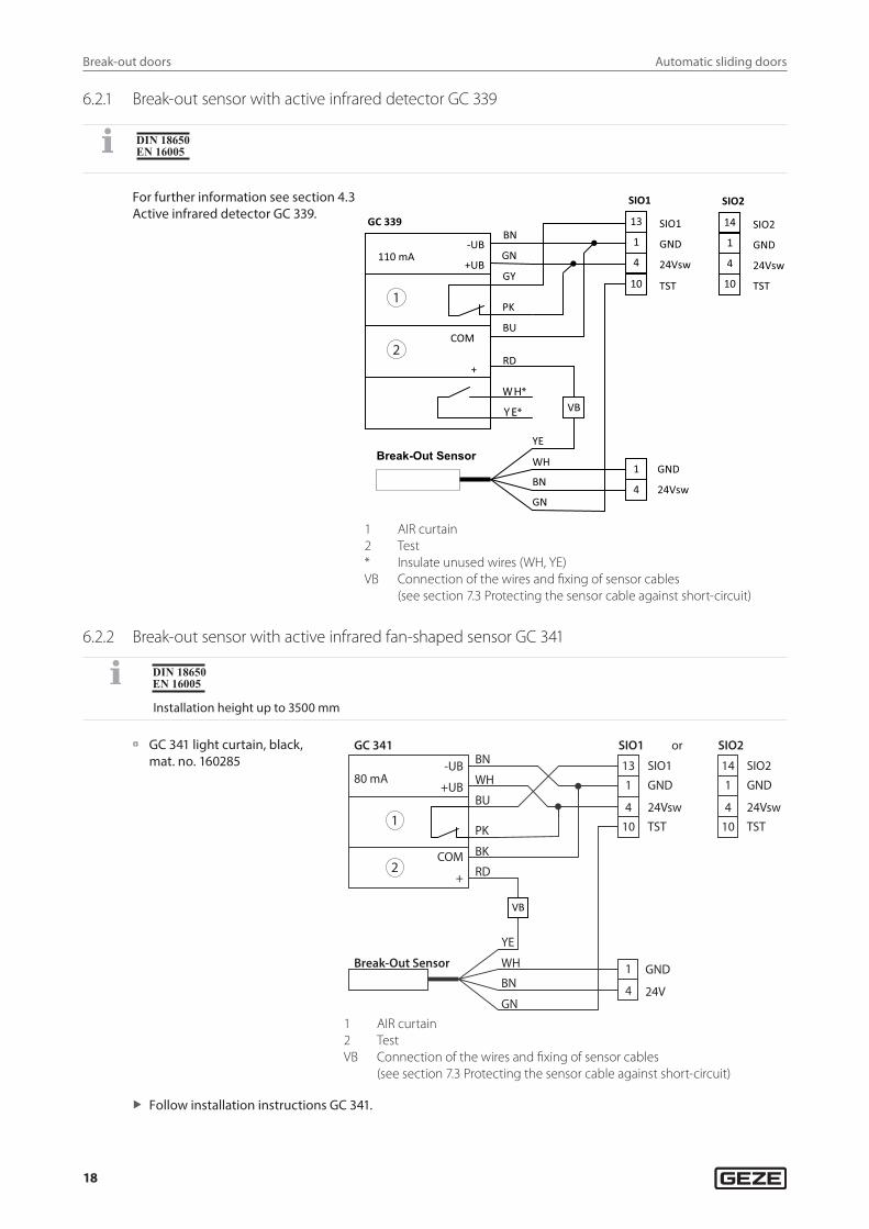
6.2.1 Break-out sensor with active infrared detector GC 339
For further information see section 4.3 Active infrared detector GC 339.
1
2
SIO1
1 GND 4 24Vsw
10 TST
13 SIO1
SIO2
1 GND
4 24Vsw 10 TST
14 SIO2
Break-Out Sensor
BN
GN
WH
YE
1 GND
4 24Vsw
VB
-UB
+UB
COM
+
BN
GN
GY
PK
BU
RD
110 mA
GC 339
W H*
Y E*
1 AIR curtain2 Test* Insulate unused wires (WH, YE)VB Connection of the wires and fixing of sensor cables
(see section 7.3 Protecting the sensor cable against short-circuit)
6.2.2 Break-out sensor with active infrared fan-shaped sensor GC 341
Installation height up to 3500 mm
à GC 341 light curtain, black, mat. no. 160285
GC 341
Break-Out Sensor
80 mA
BN
WH
BU
PK
BK
RD
YE
WH
BN
GN
COM
+
-UB
+UB
SIO1 or SIO2
131
410
SIO1GND
24Vsw
GND
24V
TST
SIO2GND
24VswTST
141
410
1
4
1
2
VB
1 AIR curtain2 TestVB Connection of the wires and fixing of sensor cables
(see section 7.3 Protecting the sensor cable against short-circuit)
X Follow installation instructions GC 341.
Automatic sliding doors
19
Break-out doors
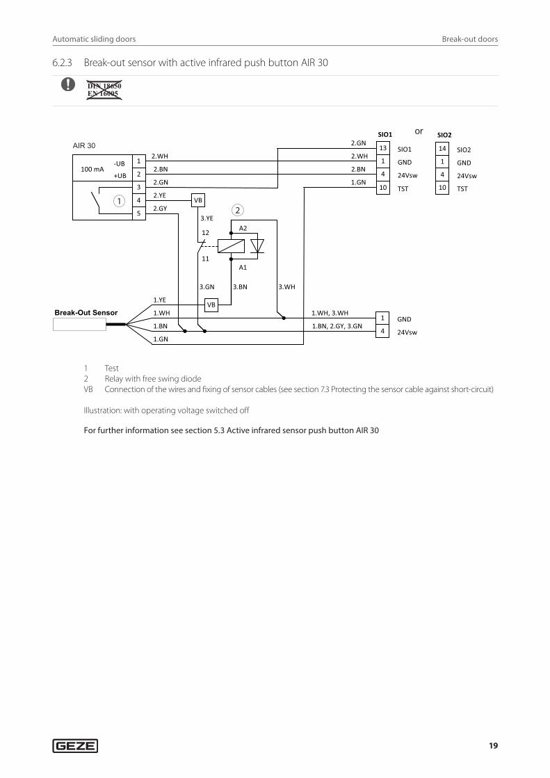
6.2.3 Break-out sensor with active infrared push button AIR 30
or
1
Break-Out Sensor
1.BN
1.GN
1.WH
1.YE
100 mA -UB
+UB
1
2
3
4
5
2.WH
2.BN
2.GN
2.YE
2.GY VB
3.YE
3.GN
12
11
A2
A1
3.BN
VB
SIO1
1 GND
4 24Vsw
10 TST
13 SIO1
SIO2
1 GND 4 24Vsw
10 TST
14 SIO2
1 GND
4 24Vsw
3.WH
1.GN
1.WH, 3.WH
1.BN, 2.GY, 3.GN
2.BN
2.WH
2.GN AIR 30
2
1 Test2 Relay with free swing diodeVB Connection of the wires and fixing of sensor cables (see section 7.3 Protecting the sensor cable against short-circuit)
Illustration: with operating voltage switched off
For further information see section 5.3 Active infrared sensor push button AIR 30
Automatic sliding doors
20
Series connection of safety sensors
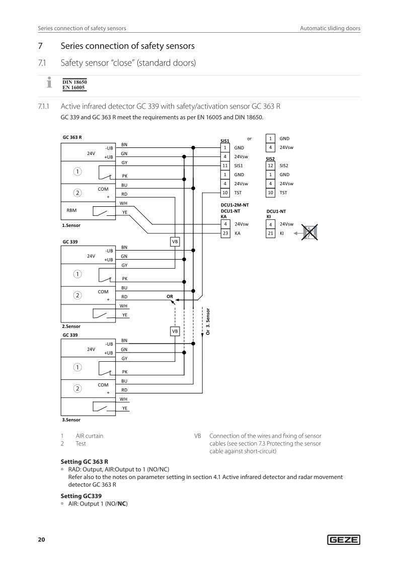
7 Series connection of safety sensors
7.1 Safety sensor “close” (standard doors)
7.1.1 Active infrared detector GC 339 with safety/activation sensor GC 363 RGC 339 and GC 363 R meet the requirements as per EN 16005 and DIN 18650.
1
2
1
2
1
2
GND 1
4 24Vsw
11 SIS1
1 GND
4 24Vsw
10 TST
SIS1 1 GND
4 24Vsw
SIS2
1 GND
4 24Vsw
10 TST
12 SIS2
or
4 24Vsw
23 KA
-DCU1-2M-NTDCU1-NT
KA
4 24Vsw
21 KI
DCU1-NT
VB
VB
OR
Or
3. S
enso
r
BN
GN
GY
PK
BU
RD
WH
YE
24V
GC 339
-UB
+UB
COM +
BN
GN
GY
PK
BU
RD
WH
YE
24V
GC 363 R
-UB
+UB
COM +
RBM
1.Sensor
2.Sensor
3.Sensor
BN
GN
GY
PK
BU
RD
WH
YE
24V
GC 339
-UB
+UB
COM +
KI
1 AIR curtain2 Test
VB Connection of the wires and fixing of sensor cables (see section 7.3 Protecting the sensor cable against short-circuit)
Setting GC 363 R à RAD: Output, AIR:Output to 1 (NO/NC)
Refer also to the notes on parameter setting in section 4.1 Active infrared detector and radar movement detector GC 363 R
Setting GC339 à AIR: Output 1 (NO/NC)
Automatic sliding doors
21
Series connection of safety sensors
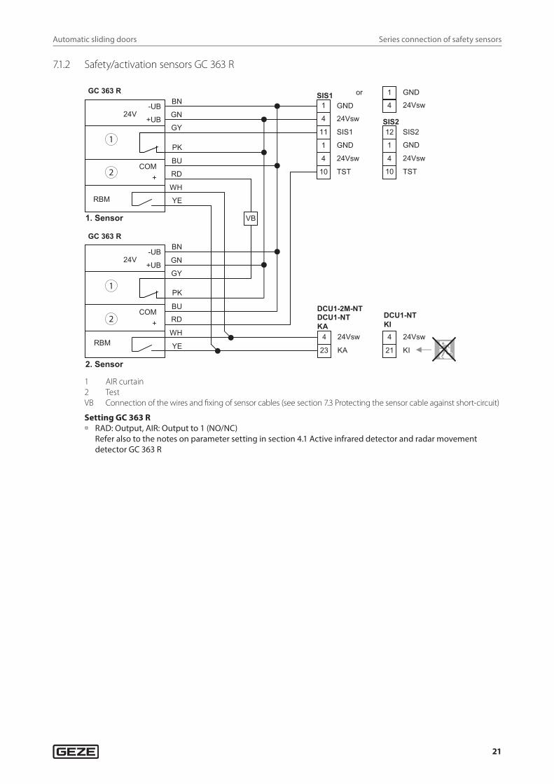
7.1.2 Safety/activation sensors GC 363 R
GND1
4 24Vsw
11 SIS1
1 GND
4 24Vsw
10 TST
SIS1 1 GND
4 24Vsw
SIS2
1 GND
4 24Vsw
10 TST
12 SIS2
or
4 24Vsw
23 KA
DCU1-2M-NTDCU1-NT KA
4 24Vsw
21 KI
DCU1-NTKI
VB
BN
GN
GY
PK
BU
RD
WH
YE
24V
GC 363 R
-UB
+UB
COM+
RBM
RBM
BN
GN
GY
PK
BU
RD
WH
YE
24V
GC 363 R
-UB
+UB
COM+
1
2
1
2
1. Sensor
2. Sensor
1 AIR curtain2 TestVB Connection of the wires and fixing of sensor cables (see section 7.3 Protecting the sensor cable against short-circuit)
Setting GC 363 R à RAD: Output, AIR: Output to 1 (NO/NC)
Refer also to the notes on parameter setting in section 4.1 Active infrared detector and radar movement detector GC 363 R
Automatic sliding doors
22
Series connection of safety sensors
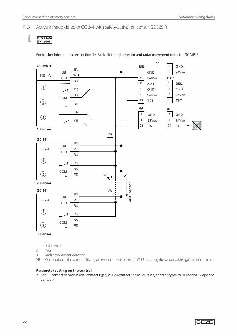
7.1.3 Active infrared detector GC 341 with safety/activation sensor GC 365 R
For further information see section 4.4 Active infrared detector and radar movement detector GC 365 R
KI
+
80 mA
COM
-UB
+UB
BN
WH
BU
PK
BK
RD
GC 341
+
80 mA
COM
-UB
+UB
BN
WH
BU
PK
BK
RD
GC 341
4 24Vsw23 KA
KA
1 GND
1 GND
SIS2
1 GND4 24Vsw10 TST
12 SIS2
or
GND1
4 24Vsw11 SIS11 GND4 24Vsw10 TST
SIS1
4 24Vsw21 KI
1 GND
4 24Vsw
VB
or
VB
or 3
. Se
nsor
1. Sensor
2. Sensor
3. Sensor
COM
+
BN
WH
BU
PK
BK
RD
GN
YE
100 mA
GC 365 R
-UB
+UB
1
2
1
2
1
2
3
1 AIR curtain2 Test3 Radar movement detectorVB Connection of the wires and fixing of sensor cables (see section 7.3 Protecting the sensor cable against short-circuit)
Parameter setting on the control X Set Ci (contact sensor inside, contact type) or Co (contact sensor outside, contact type) to 01 (normally opened
contact).
Automatic sliding doors
23
Series connection of safety sensors
7.2 Safety sensor “close” (FR doors)
7.2.1 Active infrared detector GC 339 with safety/activation sensor GC 363 SFGC 339 and GC 363 SF meet the requirements as per EN 16005 and DIN 18650.
1
2
1
2
1
2
33
GND 1
4 24Vsw
11 SIS1
1 GND
4 24Vsw
10 TST
SIS1 1 GND
4 24Vsw
SIS2
1 GND
4 24Vsw
10 TST
12 SIS2
or
4 24Vsw
21 KI
4 24Vsw
23 KA
KAKI
VB
VB
OR
Or
3. S
enso
r
BN
GN
GY
PK
BU
RD
WH
YE
24V
GC 339
-UB
+UB
COM +
1.Sensor
2.Sensor
3.Sensor
BN
GN
GY
PK
BU
RD
WH
YE
24V
GC 339
-UB
+UB
COM +
COM
+
BN
GN
GY
PK
BU
RD
WH
YE RBM
WH/BK
120 mA
GC 363 SF
YE/BK
+UB
1 AIR curtain2 Test3 not used
VB Connection of the wires and fixing of sensor cables (see section 7.3 Protecting the sensor cable against short-circuit)
Parameter setting on the control à Ci (contact sensor inside, contact type) or Co (contact sensor outside, contact type) to 04 (frequency).
Setting GC 363 R à RAD: Output, AIR: Output to 6 (freq/NC)
Refer also to the notes on parameter setting GC 363 SF in section 4.2 Active infrared detector and self-moni-tored radar movement detector GC 363 SF
Automatic sliding doors
24
Series connection of safety sensors
7.2.2 Safety/activation sensor GC 363 SF
à Two interfaces GC 363 S and two relays are required for the series connection of two GC 363 SF. à For further information see section 4.5 Active infrared detector and radar movement detector GC 365 SF
Setting the parameters: X Ci (KI contact type) to 02 (normally closed contact). X E3 (PE3 function) to 22 (KI 2).
à Accessories: à Interface GC 363 S, mat. no. 151361 à Relay with free-wheeling diode, mat. no. 103352
V
12V - 24V
RBM
GC 363 SF
Inte
rfac
e
GC
363
S
-UB
+UB
COM
++UB+UB
BN
GN
YE
GY
BU
RD
PK
WH
YE/BK
WH/BK
12V - 24V
RBM
GC 363 SF
Inte
rfac
e
GC
363
S
-UB
+UB
COM
++UB+UB
BN
GN
YE
GY
BU
RD
PK
WH
YE/BK
WH/BK
14
11
A1 (+)
A2 (-)
14
11
A1 (+)
A2 (-)
1
4
11
1
4
10
SIS
21KI
22PE3
DC
DCVB VBVB
VB VB
GND
24Vsw
SIS1
GND
24Vsw
TST
S1 1 GND
4 24Vsw
SIS2
1 GND
4 24Vsw
10 TST
12 SIS2
OR
KI1
PE33
U1-2M-NT
U1-2M-NT
1
2
1
2
33
1 AIR curtain2 Test3 Relay with free swing diode
VB Connection of the wires and fixing of sensor cables (see section 7.3 Protecting the sensor cable against short-circuit)
Illustration: with operating voltage switched off
Setting GC 363 SF à RAD: Output, AIR:Output to 5 (current/NC)
Refer also to the notes on parameter setting GC 363 SF in section 4.2 Active infrared detector and self-monitored radar movement detector GC 363 SF
Automatic sliding doors
25
Series connection of safety sensors
7.2.3 Active infrared detector GC 341 with safety/activation sensor GC 365 SF
For further information see section 4.5 Active infrared detector and radar movement detector GC 365 SF
KA
+
80 mA
COM
-UB
+UB
BN
WH
BU
PK
BK
RD
GC 341
+
80 mA
COM
-UB
+UB
BN
WH
BU
PK
BK
RD
GC 341
4 24Vsw21 KI
KI
1 GND
1 GND
SIS2
1 GND4 24Vsw10 TST
12 SIS2
or
GND1
4 24Vsw11 SIS11 GND4 24Vsw10 TST
SIS1
4 24Vsw23 KA
1 GND
4 24Vsw
COM
+
BN
WH
BU
PK
BK
RD
GN
YE
100 mA
GC 365 SF
+UB
-UB
+UB
VB
or
VB
Or 3
. Se
nsor
1. Sensor
2. Sensor
3. Sensor
1
2
1
2
1
2
3
1 AIR curtain2 Test3 Radar movement detectorVB Connection of the wires and fixing of sensor cables (see section 7.3 Protecting the sensor cable against short-cir-
cuit)
Parameter setting on the control X Set Ci (contact sensor inside, contact type) or Co (contact sensor outside, contact type) to 04 (frequency).
Automatic sliding doors
26
Series connection of safety sensors
7.3 Protecting the sensor cable against short-circuitWhen connecting the sensor cables to the plug-type connectors SIS1, SIS2, SIO1, SIO2 use the following method:
Combine several wires to be connected in one wire-end ferrule
Connect VB wires using an insulated parallel connectorParallel connectors: e.g. Bürklin, order No. 07F680
X Use shrink tubing to insulate wires until the start of the cable sheath. The shrink tubing must project 10 mm over the insulated parallel connector.
X Lay the insulated wires backwards over the cable sheaths.
X Insulate non-used wires and lay them backwards over the cable sheaths.
X Fix wires and cables using 2 cable ties.
Secure sensor cables against movement X Fix the sensor cables to the cable holder using a cable guide (1).
Automatic sliding doors
27
Mechanical contact
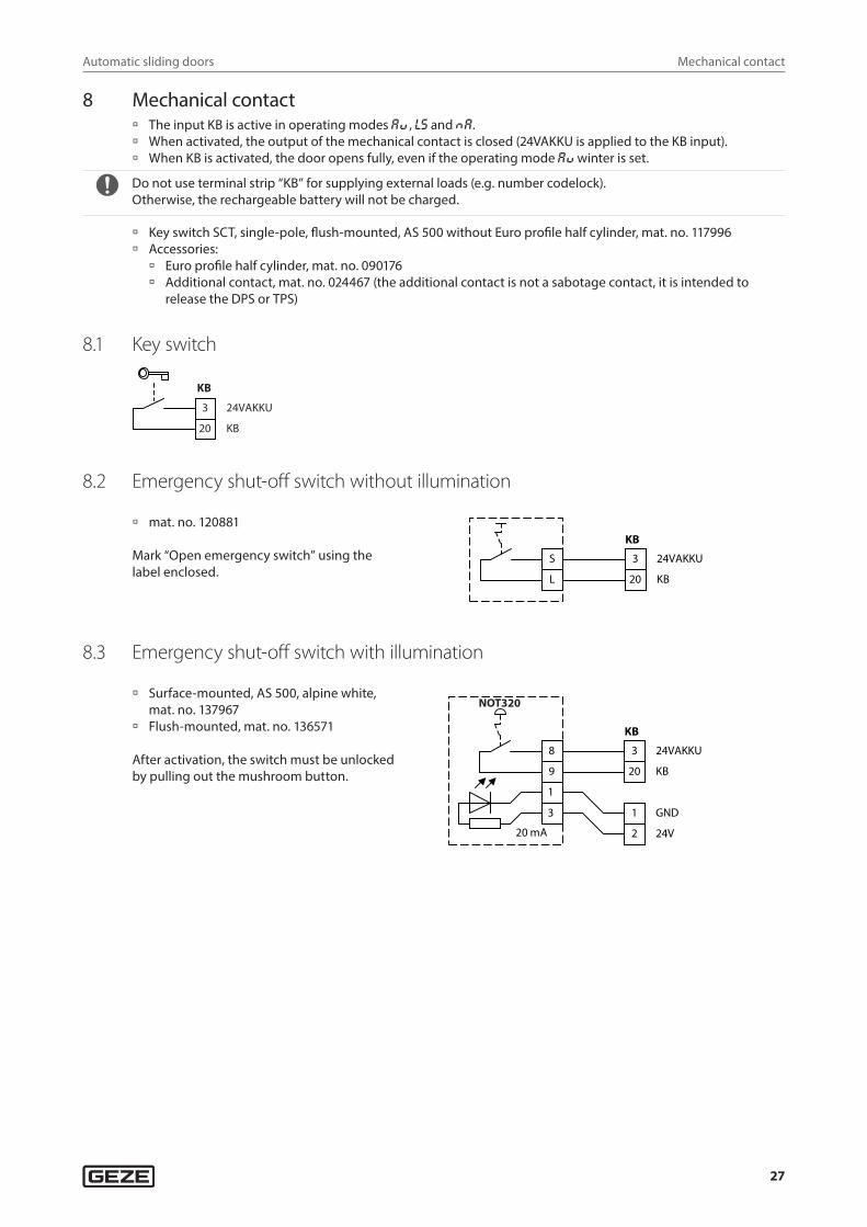
8 Mechanical contact à The input KB is active in operating modes aU , ls and Na. à When activated, the output of the mechanical contact is closed (24VAKKU is applied to the KB input). à When KB is activated, the door opens fully, even if the operating mode aU winter is set.
Do not use terminal strip “KB” for supplying external loads (e.g. number codelock). Otherwise, the rechargeable battery will not be charged.
à Key switch SCT, single-pole, flush-mounted, AS 500 without Euro profile half cylinder, mat. no. 117996 à Accessories:
à Euro profile half cylinder, mat. no. 090176 à Additional contact, mat. no. 024467 (the additional contact is not a sabotage contact, it is intended to
release the DPS or TPS)
8.1 Key switchSchlüsseltaster
20 KB
3 24VAKKU
KB
8.2 Emergency shut-off switch without illumination
à mat. no. 120881
Mark “Open emergency switch” using the label enclosed.
20 KB
3 24VAKKU
KB
L
S
8.3 Emergency shut-off switch with illumination
à Surface-mounted, AS 500, alpine white, mat. no. 137967
à Flush-mounted, mat. no. 136571
After activation, the switch must be unlocked by pulling out the mushroom button. 20 KB
3 24VAKKU
KB
2 24V
1 GND
8
9
1
3
20 mA
NOT320
Automatic sliding doors
28
Contact sensor inside
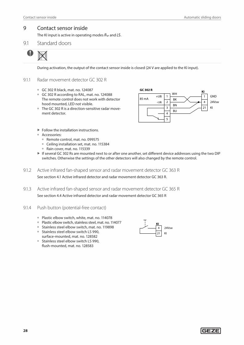
9 Contact sensor insideThe KI input is active in operating modes aU and ls.
9.1 Standard doors
During activation, the output of the contact sensor inside is closed (24 V are applied to the KI input).
9.1.1 Radar movement detector GC 302 R
à GC 302 R black, mat. no. 124087 à GC 302 R according to RAL, mat. no. 124088
The remote control does not work with detector hood mounted, LED not visible.
à The GC 302 R is a direction-sensitive radar move-ment detector.
WH
BU
BK
BN
85 mA +UB
-UB
GC 302 R
1
2
3
4
5
24Vsw
KI
GND
4
21
1 KI
X Follow the installation instructions. à Accessories:
à Remote control, mat. no. 099575 à Ceiling installation set, mat. no. 115384 à Rain cover, mat. no. 115339
X If several GC 302 Rs are mounted next to or after one another, set different device addresses using the two DIP switches. Otherwise the settings of the other detectors will also changed by the remote control.
9.1.2 Active infrared fan-shaped sensor and radar movement detector GC 363 RSee section 4.1 Active infrared detector and radar movement detector GC 363 R.
9.1.3 Active infrared fan-shaped sensor and radar movement detector GC 365 RSee section 4.4 Active infrared detector and radar movement detector GC 365 R
9.1.4 Push button (potential-free contact)
à Plastic elbow switch, white, mat. no. 114078 à Plastic elbow switch, stainless steel, mat. no. 114077 à Stainless steel elbow switch, mat. no. 119898 à Stainless steel elbow switch LS 990,
surface-mounted, mat. no. 128582 à Stainless steel elbow switch LS 990,
flush-mounted, mat. no. 128583
21 KI
4 24Vsw KI
Automatic sliding doors
29
Contact sensor inside
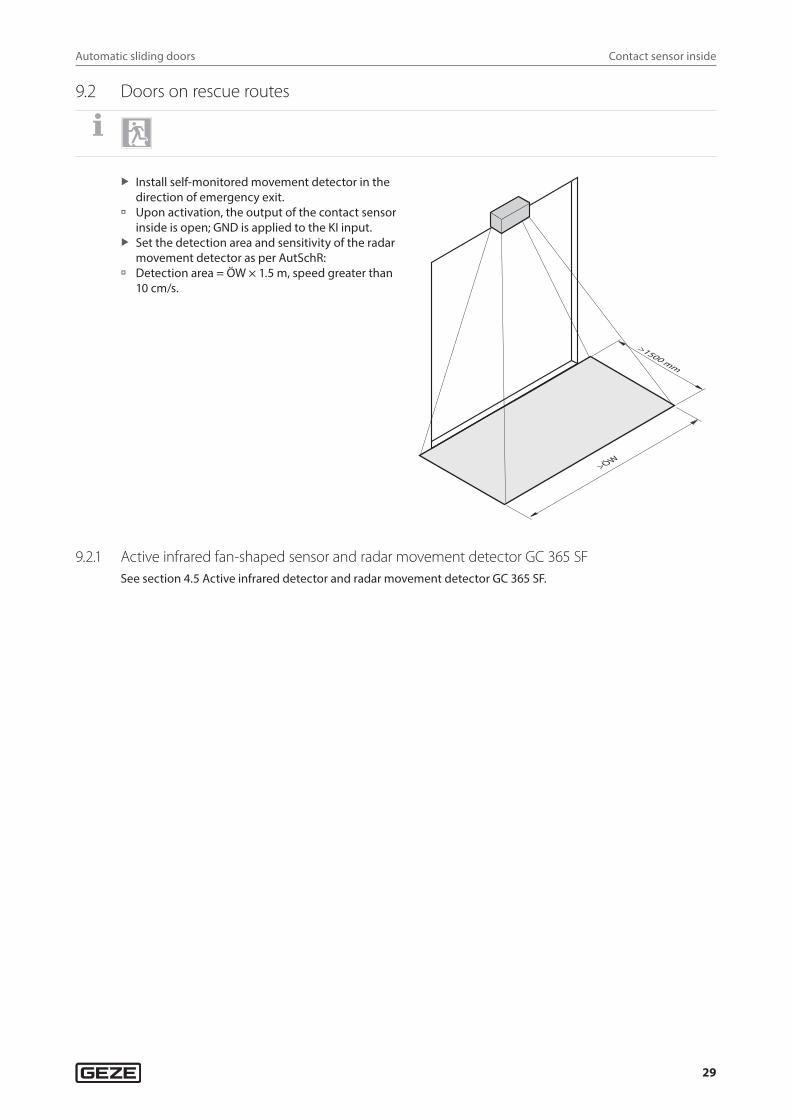
9.2 Doors on rescue routes
X Install self-monitored movement detector in the direction of emergency exit.
à Upon activation, the output of the contact sensor inside is open; GND is applied to the KI input.
X Set the detection area and sensitivity of the radar movement detector as per AutSchR:
à Detection area = ÖW × 1.5 m, speed greater than 10 cm/s.
9.2.1 Active infrared fan-shaped sensor and radar movement detector GC 365 SFSee section 4.5 Active infrared detector and radar movement detector GC 365 SF.
Automatic sliding doors
30
Contact sensor outside
10 Contact sensor outside à The KA input is only active in operating mode aU . à During activation, the output of the contact sensor outside is closed (24 V applied at the KA input).
10.1 GC 302 R radar movement detector
à See section 9.1.1 Radar movement detec-tor GC 302 R.
WH
BU
BK
BN
85 mA +UB
-UB
GC 302 R
2
1
3
4
5
24Vsw
KA
GND
4
23
1 KA
10.2 Active infrared detector and radar movement detector GC 363 RSee section 4.1 Active infrared detector and radar movement detector GC 363 R.
10.3 Active infrared fan-shaped sensor and radar movement detector GC 365 RSee section 4.4 Active infrared detector and radar movement detector GC 365 R.
10.4 Push button (potential-free contact)
à See section 9.1.4 Push button (potential-free contact).
23 KA
4 24VswKA
11 Configurable inputsThe control features three configurable inputs, PE1 (terminal 51), PE2 (terminal 52) and PE3 (terminal 22), that can be allocated different control functions. The parameter setting of the inputs can be programmed using the dis-play programme switch DPS or the service terminal ST220. The functions are described in the Service menu DPS section (2nd menu) and in the Service terminal ST220 section (configurable inputs).
11.1 Switch function
à With DPS: Set e1 , e2 or e3 to 1 0 (switch function) or 11 (switch function with closing after hold-open time).
à With ST220: Set PE1, PE2 or PE3 function to “switch function” or “switch function OHZ”.
à During activation, the push button is closed (24 V is applied to inputs PE1, PE2 and PE3). à The first switch contact opens the door and the next closes the door. à For the switch function with closing after the hold-open time, the door closes automatically after the hold-
open time elapses providing it was not closed via the push button beforehand.
Automatic sliding doors
31
Configurable inputs
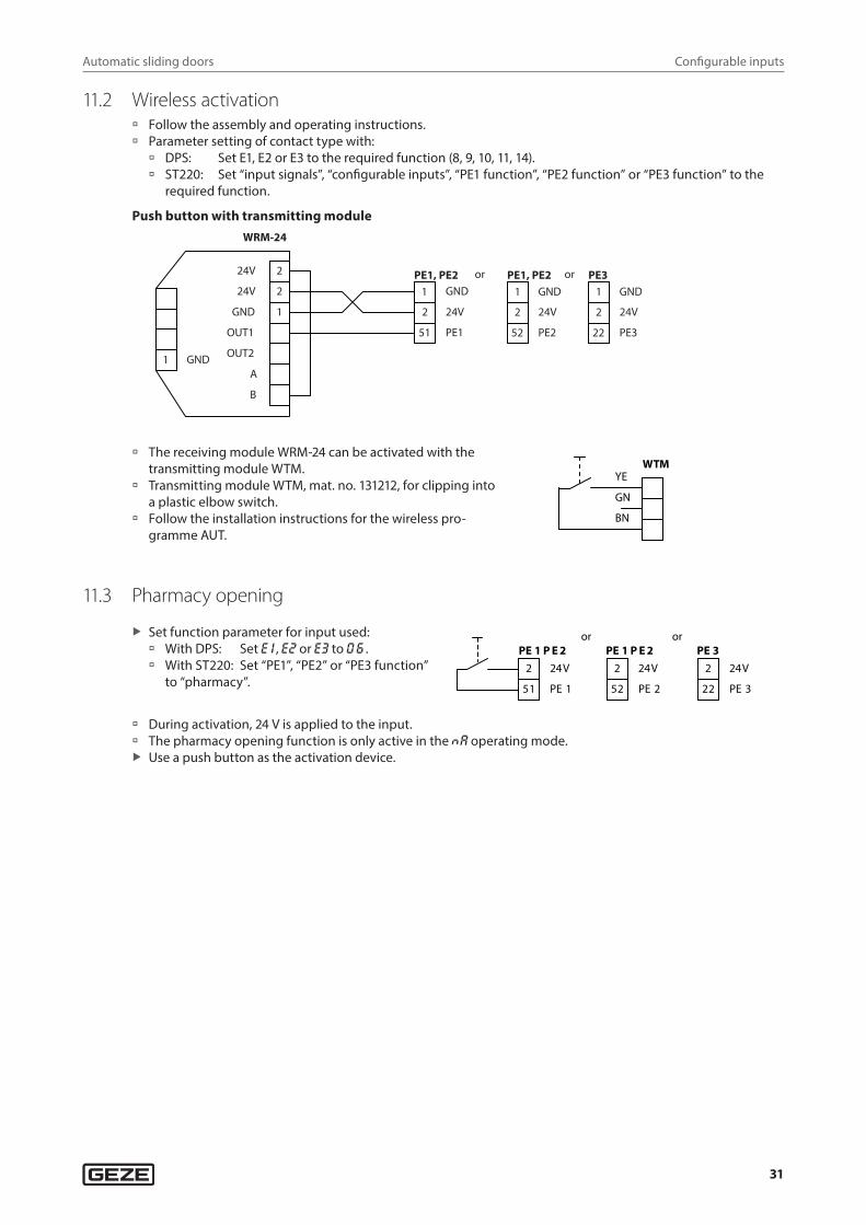
11.2 Wireless activation à Follow the assembly and operating instructions. à Parameter setting of contact type with:
à DPS: Set E1, E2 or E3 to the required function (8, 9, 10, 11, 14). à ST220: Set “input signals”, “configurable inputs”, “PE1 function”, “PE2 function” or “PE3 function” to the
required function.
Push button with transmitting module
1
WRM-24
OUT1
GN
24V
PE1
D
51
24V
GND
2
24V 2
A
OUT2
2
B
GND 1
PE1, PE2
24V
PE2
GND
2
52
1 1 PE1, PE2or
24V
PE3
GND
2
22
1 PE3or
à The receiving module WRM-24 can be activated with the transmitting module WTM.
à Transmitting module WTM, mat. no. 131212, for clipping into a plastic elbow switch.
à Follow the installation instructions for the wireless pro-gramme AUT.
WTM
BN
GN
YE
11.3 Pharmacy opening
X Set function parameter for input used: à With DPS: Set e1 , e2 or e3 to 0 6 . à With ST220: Set “PE1”, “PE2” or “PE3 function”
to “pharmacy”.
51 PE 1
2 24V
PE 1 P E 2
52 PE 2
PE 1 P E 2or
2 24V
22 PE 3
PE 3or
2 24V
à During activation, 24 V is applied to the input. à The pharmacy opening function is only active in the Na operating mode. X Use a push button as the activation device.
Automatic sliding doors
32
Configurable inputs
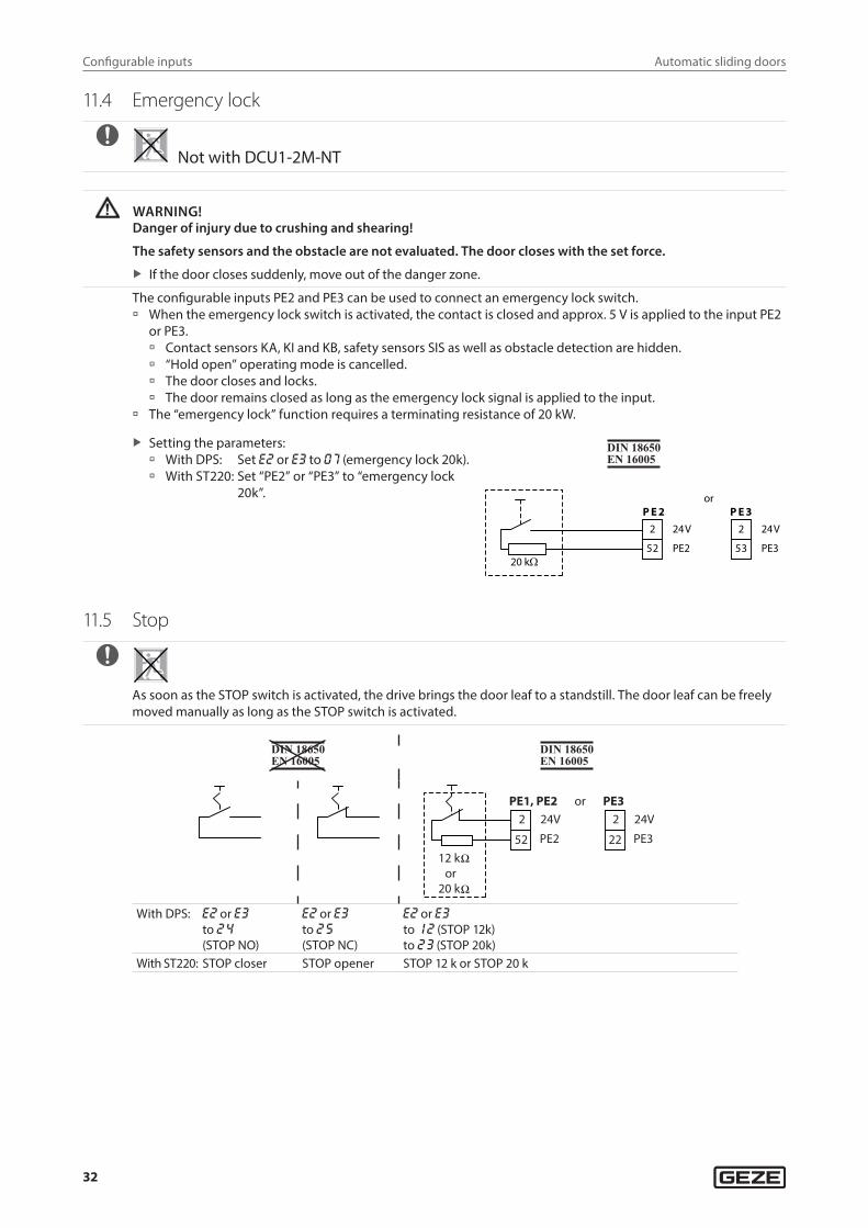
11.4 Emergency lock
Not with DCU1-2M-NT
WARNING!Danger of injury due to crushing and shearing!
The safety sensors and the obstacle are not evaluated. The door closes with the set force.
X If the door closes suddenly, move out of the danger zone.
The configurable inputs PE2 and PE3 can be used to connect an emergency lock switch. à When the emergency lock switch is activated, the contact is closed and approx. 5 V is applied to the input PE2
or PE3. à Contact sensors KA, KI and KB, safety sensors SIS as well as obstacle detection are hidden. à “Hold open” operating mode is cancelled. à The door closes and locks. à The door remains closed as long as the emergency lock signal is applied to the input.
à The “emergency lock” function requires a terminating resistance of 20 kW.
X Setting the parameters: à With DPS: Set e2 or e3 to 07 (emergency lock 20k). à With ST220: Set “PE2” or “PE3” to “emergency lock
20k”.
2 24V
52 PE2
P E 22 24V
53 PE3
P E 3or
20 kΩ
11.5 Stop
As soon as the STOP switch is activated, the drive brings the door leaf to a standstill. The door leaf can be freely moved manually as long as the STOP switch is activated.
cN = 01
PE1, PE224V2
52 PE2
12 kor
20 k
PE324V2
22 PE3
or
With DPS: e2 or e3to 24
(STOP NO)
e2 or e3to 25
(STOP NC)
e2 or e3to 12 (STOP 12k)to 23 (STOP 20k)
With ST220: STOP closer STOP opener STOP 12 k or STOP 20 k
Automatic sliding doors
33
WC control
For personal protection as per DIN 18650 and EN 16005: X Connect terminating resistance to monitor the input in accordance with the configuration.
Voltage of terminal PE2 or PE3 to GNDSTOP 12kNot activated 7.4 VActivated or cable break 0 VCable short-circuit 24 VSTOP 20kNot activated 5.1 VActivated or cable break 0 VCable short-circuit 24 V
12 WC control(not with DCU1-2M-NT)
Setting the parameters, with: à DPS:
à Set E1, E2 or E3 to 21 (WC control), depending on the input used. à Set A1 to 14 (LS). à Set A2 to 24 (fault WC timeout) if monitoring of permanent locking is required (signal horn to the lodge) à Set AC to 01 (open) or 03 (battery operation max. 30 minutes / 30 cycles, then open).
à ST220: à Set “input signals”, “PE1 function”, “PE2 function” or “PE3 function” to “WC control”. à Set “output signals”, “PA1 function” to “exit only”. à Set “Door parameters”, “Power failure not NA” to “open” or “30 min open”.
Accessories: à AS 500 switch unit with illuminated display for disabled WC, mat. no. 120882 (2 pieces required) à Plastic elbow switch, white, mat. no. 114078 à Plastic elbow switch, stainless steel, mat. no. 114077 à Stainless steel elbow switch, mat. no. 119898 à Stainless steel elbow switch LS 990, surface-mounted, mat. no. 128582 à Stainless steel elbow switch LS 990, flush-mounted, mat. no. 128583 à SLE220 signal light, flush-mounted, AS500, AW, mat. no. 115934 à Optional: SLH220, SIGNAL HORN, flush-mounted, AS 500, AW, COMPLETE, mat. no. 115939
Automatic sliding doors
34
WC control
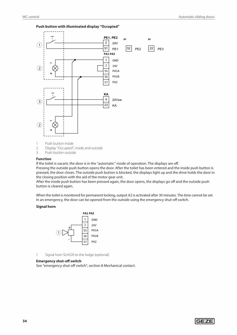
Push button with illuminated display “Occupied”
1
2
2
3
GND 1
2 24V
55
56
PA1 PA2
57
PA1A
PA1B
PA2
KA
23 KA
4 24Vsw
PE1, PE2
51 PE1
2 24V 52 PE2 22 PE3
or or
–
–
+
+
1 Push button inside2 Display “Occupied”, inside and outside3 Push button outside
FunctionIf the toilet is vacant, the door is in the “automatic” mode of operation. The displays are off.Pressing the outside push button opens the door. After the toilet has been entered and the inside push button is pressed, the door closes. The outside push button is blocked, the displays light up and the drive holds the door in the closing position with the aid of the motor gear unit. After the inside push button has been pressed again, the door opens, the displays go off and the outside push button is cleared again.
When the toilet is monitored for permanent locking, output A2 is activated after 30 minutes. The time cannot be set. In an emergency, the door can be opened from the outside using the emergency shut-off switch.
Signal horn
GND 1
2 24V
55
56
PA1 PA2
57
PA1A
PA1B
PA2
+
- 1
1 Signal horn SLH220 to the lodge (optional)
Emergency shut-off switchSee “emergency shut-off switch”, section 8 Mechanical contact.
Automatic sliding doors
35
Interlocking door system, vestibule
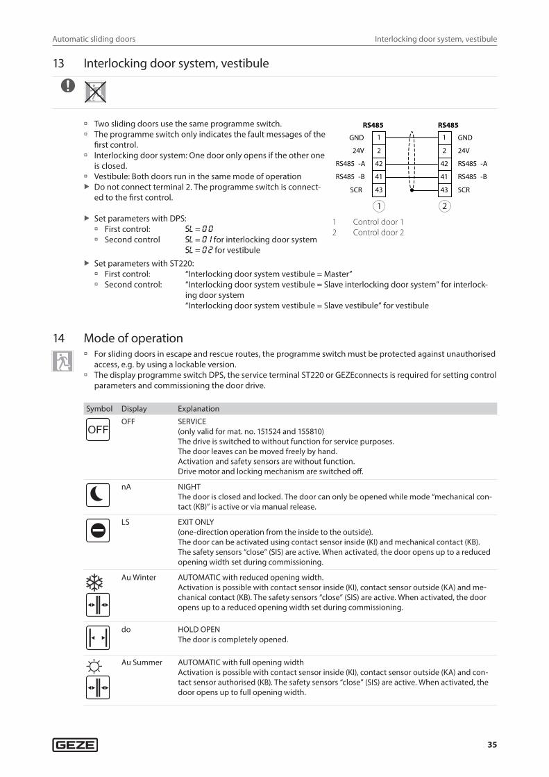
13 Interlocking door system, vestibule
à Two sliding doors use the same programme switch. à The programme switch only indicates the fault messages of the
first control. à Interlocking door system: One door only opens if the other one
is closed. à Vestibule: Both doors run in the same mode of operation X Do not connect terminal 2. The programme switch is connect-
ed to the first control.
X Set parameters with DPS: à First control: sl = 0 0
à Second control sl = 01 for interlocking door system sl = 02 for vestibule
1 GND
2 24V
42RS485 -A
41RS485 -B
43SCR
RS485
GND1
2 24V
42 RS485 -A
41 RS485 -B
43 SCR
RS485
1 2
1 Control door 12 Control door 2
X Set parameters with ST220: à First control: “Interlocking door system vestibule = Master” à Second control: “Interlocking door system vestibule = Slave interlocking door system” for interlock-
ing door system “Interlocking door system vestibule = Slave vestibule” for vestibule
14 Mode of operation à For sliding doors in escape and rescue routes, the programme switch must be protected against unauthorised
access, e.g. by using a lockable version. à The display programme switch DPS, the service terminal ST220 or GEZEconnects is required for setting control
parameters and commissioning the door drive.
Symbol Display Explanation
OFFOFF SERVICE
(only valid for mat. no. 151524 and 155810)The drive is switched to without function for service purposes.The door leaves can be moved freely by hand.Activation and safety sensors are without function.Drive motor and locking mechanism are switched off.
nA NIGHTThe door is closed and locked. The door can only be opened while mode “mechanical con-tact (KB)” is active or via manual release.
LS EXIT ONLY (one-direction operation from the inside to the outside).The door can be activated using contact sensor inside (KI) and mechanical contact (KB). The safety sensors “close” (SIS) are active. When activated, the door opens up to a reduced opening width set during commissioning.
Au Winter AUTOMATIC with reduced opening width.Activation is possible with contact sensor inside (KI), contact sensor outside (KA) and me-chanical contact (KB). The safety sensors “close” (SIS) are active. When activated, the door opens up to a reduced opening width set during commissioning.
do HOLD OPEN The door is completely opened.
Au Summer AUTOMATIC with full opening widthActivation is possible with contact sensor inside (KI), contact sensor outside (KA) and con-tact sensor authorised (KB). The safety sensors “close” (SIS) are active. When activated, the door opens up to full opening width.
Automatic sliding doors
36
Mode of operation
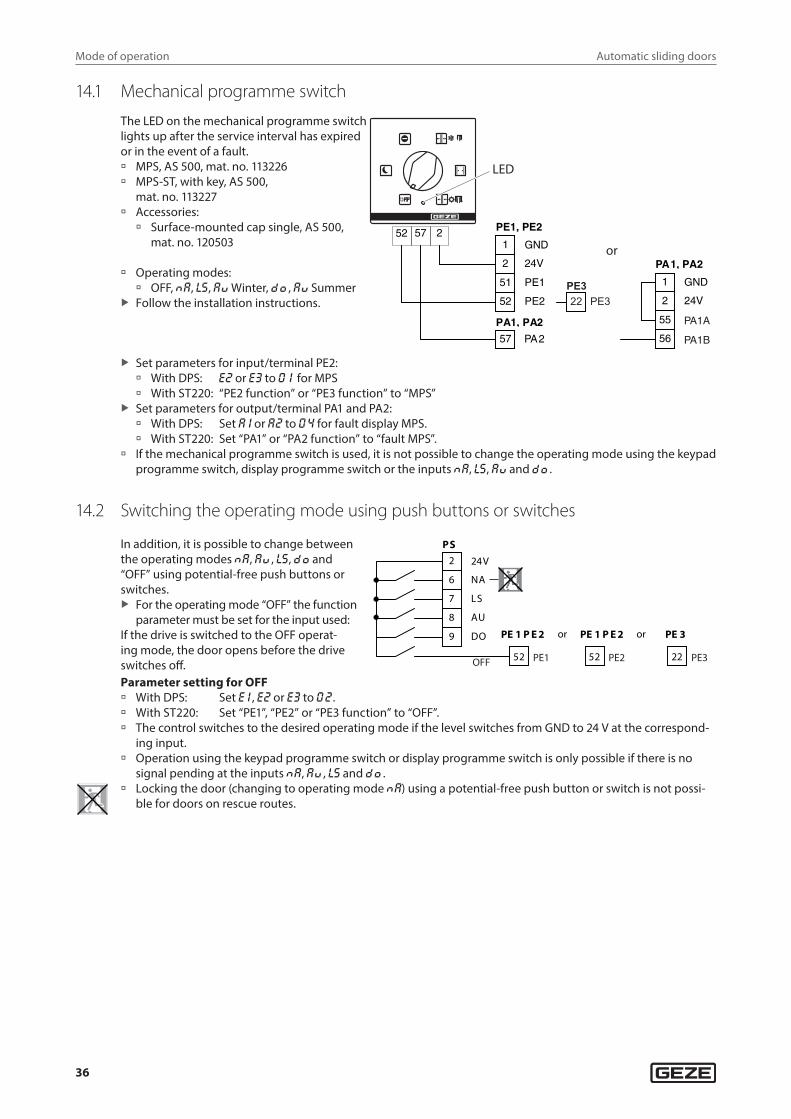
14.1 Mechanical programme switch
The LED on the mechanical programme switch lights up after the service interval has expired or in the event of a fault. à MPS, AS 500, mat. no. 113226 à MPS-ST, with key, AS 500,
mat. no. 113227 à Accessories:
à Surface-mounted cap single, AS 500, mat. no. 120503
à Operating modes: à OFF, Na, ls, aU Winter, DO , aU Summer
X Follow the installation instructions.
LED
or
22 PE3PE3
X Set parameters for input/terminal PE2: à With DPS: e2 or e3 to 01 for MPS à With ST220: “PE2 function” or “PE3 function” to “MPS”
X Set parameters for output/terminal PA1 and PA2: à With DPS: Set a1 or a2 to 04 for fault display MPS. à With ST220: Set “PA1” or “PA2 function” to “fault MPS”.
à If the mechanical programme switch is used, it is not possible to change the operating mode using the keypad programme switch, display programme switch or the inputs Na, ls, aU and DO .
14.2 Switching the operating mode using push buttons or switches
In addition, it is possible to change between the operating modes Na, aU , ls, DO and “OFF” using potential-free push buttons or switches.
X For the operating mode “OFF” the function parameter must be set for the input used:
If the drive is switched to the OFF operat-ing mode, the door opens before the drive switches off.
24V2
6 NA
7 LS
8 AU
9 DO
PS
PE 1 P E 2 PE 1 P E 2 PE 3
52 52
or or
PE1 PE2 22 PE3OFF
Parameter setting for OFF à With DPS: Set e1 , e2 or e3 to 02. à With ST220: Set “PE1”, “PE2” or “PE3 function” to “OFF”. à The control switches to the desired operating mode if the level switches from GND to 24 V at the correspond-
ing input. à Operation using the keypad programme switch or display programme switch is only possible if there is no
signal pending at the inputs Na, aU , ls and DO . à Locking the door (changing to operating mode Na) using a potential-free push button or switch is not possi-
ble for doors on rescue routes.
Automatic sliding doors
37
Mode of operation
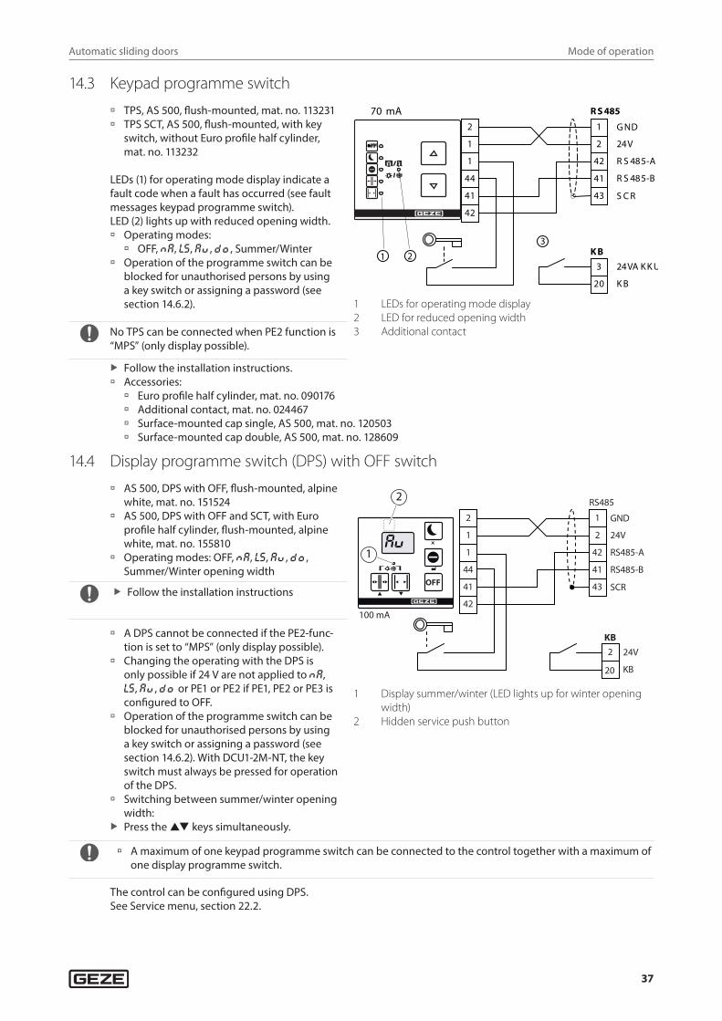
14.3 Keypad programme switch
à TPS, AS 500, flush-mounted, mat. no. 113231 à TPS SCT, AS 500, flush-mounted, with key
switch, without Euro profile half cylinder, mat. no. 113232
LEDs (1) for operating mode display indicate a fault code when a fault has occurred (see fault messages keypad programme switch).LED (2) lights up with reduced opening width. à Operating modes:
à OFF, Na, ls, aU , DO , Summer/Winter à Operation of the programme switch can be
blocked for unauthorised persons by using a key switch or assigning a password (see section 14.6.2).
No TPS can be connected when PE2 function is “MPS” (only display possible).
2
1
1
44
41
42
G ND1
2 24V
42 R S 485-A
41 R S 485-B
S C R43
R S 48570 mA
20 K B
3 24VA K K U
Zus atzkontakt K B 1 2
3
1 LEDs for operating mode display2 LED for reduced opening width3 Additional contact
X Follow the installation instructions. à Accessories:
à Euro profile half cylinder, mat. no. 090176 à Additional contact, mat. no. 024467 à Surface-mounted cap single, AS 500, mat. no. 120503 à Surface-mounted cap double, AS 500, mat. no. 128609
14.4 Display programme switch (DPS) with OFF switch
à AS 500, DPS with OFF, flush-mounted, alpine white, mat. no. 151524
à AS 500, DPS with OFF and SCT, with Euro profile half cylinder, flush-mounted, alpine white, mat. no. 155810
à Operating modes: OFF, Na, ls, aU , DO , Summer/Winter opening width
X Follow the installation instructions
à A DPS cannot be connected if the PE2-func-tion is set to “MPS” (only display possible).
à Changing the operating with the DPS is only possible if 24 V are not applied to Na, ls, aU , DO or PE1 or PE2 if PE1, PE2 or PE3 is configured to OFF.
à Operation of the programme switch can be blocked for unauthorised persons by using a key switch or assigning a password (see section 14.6.2). With DCU1-2M-NT, the key switch must always be pressed for operation of the DPS.
à Switching between summer/winter opening width:
X Press the keys simultaneously.
2
1
1
44
41
42
GND1
2 24V
42 RS485-A
41 RS485-B
SCR43
RS485
100 mA
OFF
2
1
20 KB
2 24V
KB
1 Display summer/winter (LED lights up for winter opening width)
2 Hidden service push button
à A maximum of one keypad programme switch can be connected to the control together with a maximum of one display programme switch.
The control can be configured using DPS.See Service menu, section 22.2.
Automatic sliding doors
38
Mode of operation
Accessories: à Key switch SCT, single-pole, flush-mounted, AS 500 without Euro profile half cylinder, mat. no. 117996 à Euro profile half cylinder, mat. no. 090176 à Additional contact, mat. no. 024467 à Surface-mounted cap single, AS 500, mat. no. 120503 à Surface-mounted cap double, AS 500, mat. no. 128609
14.5 Reset function (DPS with OFF switch, TPS)In the OFF operating mode, the keys and can be pressed at the same time to trigger a software reset. The drive then behaves in the same way as after mains voltage switch-on and carries out initialisation. The parameter settings are not changed.
14.6 Blocking or releasing operation of TPS and DPS
14.6.1 With additional key switch (1st possibility)
With automatic standard sliding doors X Press the key switch briefly to block function.
à With the DPS, the function “operation blocked” is signalled by the display “- -” when any key is pressed. à With the TPS, the function “operation blocked” is signalled by the LED for the respectively set mode of
operation flashing once when any key is pressed. X Turn key switch again briefly for release. Operation is then permanently released.
For automatic sliding doors on escape and rescue routes X The key switch has to be pressed permanently for operation. X Operation is blocked as soon as the key switch is no longer pressed.
à With the DPS, the function “operation blocked” is signalled by the display “- -” when any key is pressed. à With the TPS, the function “operation blocked” is signalled by the LED for the respectively set mode of
operation flashing once when any key is pressed.
14.6.2 Release with password (2nd possibility)This requires previous setting of the 2-digit password in the drive Service menu (factory setting: no password). à For release on the TPS: X Enter the first digit of the password by the number of times the key is pressed, with
à TPS: Key
à DPS: Key
Enter the second digit of the password by the number of times the key is pressed, with
à TPS: Key
à DPS: Key
Confirm password, with à TPS: Press the and keys at the same time
à DPS: Key
à After the password has been entered, operation of the programme switch has been released. à Operation is locked automatically 2 minutes after the last key has been pressed. With the TPS, the function
“operation blocked” is signalled by the LED for the respectively set mode of operation flashing once when any key is pressed. With the DPS, the function “operation blocked” is signalled by the display “- -” when any key is pressed.
Automatic sliding doors
39
Configurable outputs
14.6.3 Permanent release of programme switch operation X For permanent release, either fit a jumper between terminals 1-44 of the TPS or DPS.
or X Set the value “00” (factory setting) as the password in the Service menu.
15 Configurable outputsThe control indicates various states via the two configurable outputs PA1 and PA2 (see Service menu). Parameters must be set for the outputs accordingly.
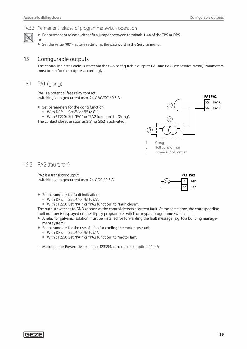
15.1 PA1 (gong)
PA1 is a potential-free relay contact, switching voltage/current max. 24 V AC/DC / 0.5 A.
X Set parameters for the gong function: à With DPS: Set a1 or a2 to 01 . à With ST220: Set “PA1” or “PA2 function” to “Gong”.
The contact closes as soon as SIS1 or SIS2 is activated.
55 PA1A
56 PA1B
PA1 PA2
3
2
1
1 Gong2 Bell transformer3 Power supply circuit
15.2 PA2 (fault, fan)
PA2 is a transistor output, switching voltage/current max. 24 V DC / 0.5 A.
PA1 PA2
57 PA2
2 24V
X Set parameters for fault indication: à With DPS: Set a1 or a2 to 02. à With ST220: Set “PA1” or “PA2 function” to “fault closer”.
The output switches to GND as soon as the control detects a system fault. At the same time, the corresponding fault number is displayed on the display programme switch or keypad programme switch.
X A relay for galvanic isolation must be installed for forwarding the fault message (e.g. to a building manage-ment system).
X Set parameters for the use of a fan for cooling the motor gear unit: à With DPS: Set a1 or a2 to 07 . à With ST220: Set “PA1” or “PA2 function” to “motor fan”.
à Motor fan for Powerdrive, mat. no. 123394, current consumption 40 mA
Automatic sliding doors
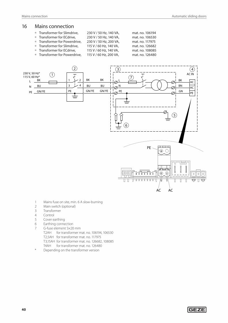
40
Mains connection
16 Mains connection à Transformer for Slimdrive, 230 V / 50 Hz, 140 VA, mat. no. 106194 à Transformer for ECdrive, 230 V / 50 Hz, 140 VA, mat. no. 106530 à Transformer for Powerdrive, 230 V / 50 Hz, 200 VA, mat. no. 117975 à Transformer for Slimdrive, 115 V / 60 Hz, 140 VA, mat. no. 126682 à Transformer for ECdrive, 115 V / 60 Hz, 140 VA, mat. no. 108085 à Transformer for Powerdrive, 115 V / 60 Hz, 200 VA, mat. no. 126480
BK
BU
GN/YE
L
N
PE
PE
1
3
2
4
BK
BU
GN/YE
BK
BU
GN/YE
AC IN
AC
PE
AC
GN
BN
BK
PE
N
L
230 V, 50 Hz* 115 V, 60 Hz*
1
2 3
7
4
5
6
PE
AC AC
1 Mains fuse on site, min. 6 A slow-burning2 Main switch (optional)3 Transformer4 Control5 Cover earthing6 Earthing connection7 G-fuse element 5×20 mm
T2AH for transformer mat. no. 106194, 106530 T2,5AH for transformer mat. no. 117975 T3,15AH for transformer mat. no. 126682, 108085 T4AH for transformer mat. no. 126480
* Depending on the transformer version
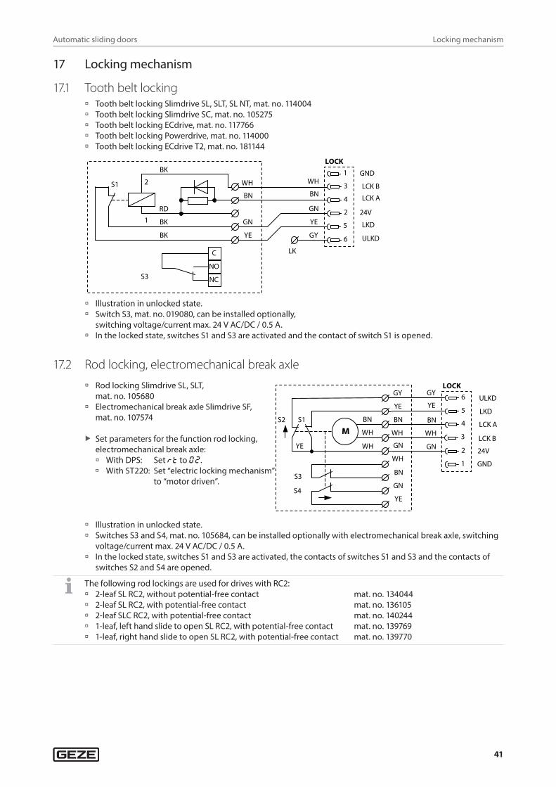
Automatic sliding doors
41
Locking mechanism
17 Locking mechanism
17.1 Tooth belt locking à Tooth belt locking Slimdrive SL, SLT, SL NT, mat. no. 114004 à Tooth belt locking Slimdrive SC, mat. no. 105275 à Tooth belt locking ECdrive, mat. no. 117766 à Tooth belt locking Powerdrive, mat. no. 114000 à Tooth belt locking ECdrive T2, mat. no. 181144
WH
BN
GN
YE
GY 6 Entriegelt
5 Verriegelt
2 24V
4 Riegel A
3 Riegel B
1 GND
LOCK
LK
S1
2
1
BK
RD
BK
BK
WH
BN
GN
YE
C
NO
NCS3
LCK B
LCK A
LKD
ULKD
à Illustration in unlocked state. à Switch S3, mat. no. 019080, can be installed optionally,
switching voltage/current max. 24 V AC/DC / 0.5 A. à In the locked state, switches S1 and S3 are activated and the contact of switch S1 is opened.
17.2 Rod locking, electromechanical break axle
à Rod locking Slimdrive SL, SLT, mat. no. 105680
à Electromechanical break axle Slimdrive SF, mat. no. 107574
X Set parameters for the function rod locking, electromechanical break axle: à With DPS: Set ®T to 02. à With ST220: Set “electric locking mechanism”
to “motor driven”.
GY
YE
BN
WH
GN 2 24V
3 Riegel B
4 Riegel A
5 Verriegelt
6 Entriegelt
1 GND
LOCK
BN
WH
WH
GY
YE
BN
WH
GN
WH
BN
GN
YE
S3
YE
S4
S2 S1
M
ULKD
LKD
LCK A
LCK B
à Illustration in unlocked state. à Switches S3 and S4, mat. no. 105684, can be installed optionally with electromechanical break axle, switching
voltage/current max. 24 V AC/DC / 0.5 A. à In the locked state, switches S1 and S3 are activated, the contacts of switches S1 and S3 and the contacts of
switches S2 and S4 are opened.
The following rod lockings are used for drives with RC2: à 2-leaf SL RC2, without potential-free contact mat. no. 134044 à 2-leaf SL RC2, with potential-free contact mat. no. 136105 à 2-leaf SLC RC2, with potential-free contact mat. no. 140244 à 1-leaf, left hand slide to open SL RC2, with potential-free contact mat. no. 139769 à 1-leaf, right hand slide to open SL RC2, with potential-free contact mat. no. 139770
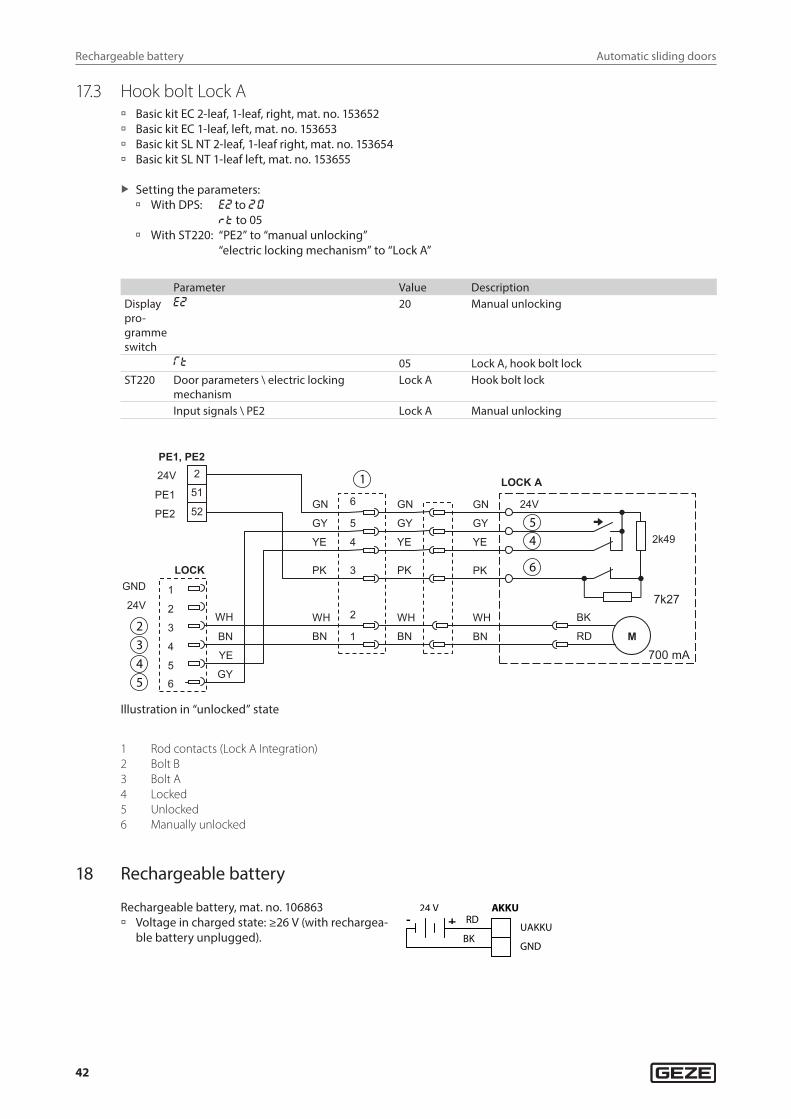
Automatic sliding doors
42
Rechargeable battery
17.3 Hook bolt Lock A à Basic kit EC 2-leaf, 1-leaf, right, mat. no. 153652 à Basic kit EC 1-leaf, left, mat. no. 153653 à Basic kit SL NT 2-leaf, 1-leaf right, mat. no. 153654 à Basic kit SL NT 1-leaf left, mat. no. 153655
X Setting the parameters: à With DPS: e2 to 20
®T to 05 à With ST220: “PE2” to “manual unlocking”
“electric locking mechanism” to “Lock A”
Parameter Value DescriptionDisplay pro-gramme switch
e2 20 Manual unlocking
RT 05 Lock A, hook bolt lockST220 Door parameters \ electric locking
mechanismLock A Hook bolt lock
Input signals \ PE2 Lock A Manual unlocking
LOCKGND
24V
6
5YE
1
2
3WH
4
GY
BN
PE1, PE2
51PE1
2 24V
BK
MRD
WH
BN
2k49
7k27
24V
PK
YE
GY
GN
WH
BN
PK
YE
GY
GN
LOCK A
WH
BN
PK
YE
GY
GN52PE2
6
5
4
3
2
1
5
1
4
6
2345
700 mA
Illustration in “unlocked” state
1 Rod contacts (Lock A Integration)2 Bolt B3 Bolt A4 Locked5 Unlocked6 Manually unlocked
18 Rechargeable battery
Rechargeable battery, mat. no. 106863 à Voltage in charged state: ≥26 V (with rechargea-
ble battery unplugged).
BK
AKKU
GND
UAKKU+ - RD24 V
Automatic sliding doors
43
Motor gear unit
19 Motor gear unit
Motor gear unit 1: Motor gear unit DCU1, mat. no. 105009.
Motor gear unit 2: Only with tandem motor DCU1-2M, mat. no. 102517.
6 A
+
Motor 1M
3 Schirm2
1Motor_B
Motor_A
M1
Temperaturfühler
1
2
Encoder
WH
GN
YE
BK
BN
RD
OG
1 Schirm
2 Thermo
3 GND
4 GND
5 5V
7 B
Encoder
Motor 2M
1 Schirm2
3
Motor_B
Motor_A
M2
+
WH
BN
WH
BN
ENC
Temp
SHLD
SHLD
M1 B
M1 A
SHLD
M2 B
M2 A
ENC
2
1
3
–
–
1 Temperature sensor2 Motor gear unit 13 Motor gear unit 2
Automatic sliding doors
44
Control
20 Control
Control DCU1-NT, mat. no. 158615.Terminal bag DCU1-NT, mat. no. 158631.
Control DCU1-2M-NT, mat. no. 158616.Terminal bag DCU1-NT, mat. no. 158631.
à DCU1-NT and DCU1-2M-NT:
à F1 24 V EXT (T1.25 A, 5x20 mm)
à F2 AC IN (6.3 AT, 5x20 mm)
à F3 RECHARGEABLE BATTERY (6.3 AT, 5x20 mm)
à RUN1 RUN-LED, µController 1
à P µR1 Programming connector, µController 1
à M1 Motor gear unit 1
à DCU1-2M-NT, in addition:
à F4 AC IN (T6.3 A; 5×20 mm)
à F5 RECHARGEABLE BATTERY (T6.3 A; 5×20 mm)
à RUN2 RUN-LED, µController 2
à P µR2 Programming connector, µController 2
à M2 Motor gear unit 2
à RUN-LED
à LED on: Everything OK
à LED flashes slowly (0.25 Hz): Drive not taught
à LED flashes quickly (2 Hz): Fault
à CAN interface CAN/CAN-ISOL mat. no. 119952 à CAN interface CAN/CAN mat. no. 189521
(see respective supplementary sheets)
CAN
KI KA SIS2
PS KB RS485 LOCK
PE1 PE2 PE3 PA1 PA2
RUN1
P µR
1
SIO1 SIO2
F1 T1,25A
F5 T6,3A
F4 T6,3A
F2 T6,3A
F3 T6,3A
P µR2
CAN
RUN2
AKKU
ENCO
DER
AC IN
M 1
M 2
SIS1
DCU110
JTAG
SPI NST
Automatic sliding doors
45
Commissioning and service
21 Commissioning and serviceCommissioning and service can be carried out using the display programme switch DPS or the service terminal ST220.
21.1 Production testThe production test is used for functional testing of the power supply, control, motor gear unit, rechargeable bat-tery and locking mechanisms (if present). The production test is carried out on the drive before it is installed on the wall and without sliding leaves.
DANGERDanger of fatal injury due to electric shock.
X Interrupt power supply.
X Connect power supply to 230 V AC and use an r.c.c.b. X Connect the rechargeable battery. X Lock the locking mechanism (if present) by hand. The bolt comb must fully engage in the toothed belt. X Connect the display programme switch.
X Connect terminals 1 and 44 of the display programme switch.
X Reset the control to factory settings using cp, display programme switch indicates le. X Press the service key and aU simultaneously (see Service menu, operation DPS), the production test starts:
à p1 Locking mechanism unlocked. à p3 Motor gear unit turns by approx. 20 cm in one direction and then approx. 20 cm in the other direction. à p2 Locking mechanism locked. à p6 Check whether or not a rechargeable battery is connected. à a0 Rechargeable battery was not detected. à a1 Rechargeable battery was detected.
à If a rechargeable battery is connected, it must be detected. It is only checked whether the rechargeable bat-tery is present and not whether the charge state of the battery is sufficient.
à If a fault occurs during the production test, the test is aborted and the fault displayed. X Press the key. X With ST220, start the production test via the Service menu under the item “Start production test yes”. X Unplug the rechargeable battery after the production test and leave it unplugged until commissioning.
21.2 Commissioning
21.2.1 Assembly and installation à Installation is complete (see installation instructions of the corresponding sliding door drive). à Sensors are correctly configured and aligned. X Clear the sensor detection area.
à Electrical installation is complete. There are no cables in the travel path of the leaves and drivers. All cables have been secured with cable ties.
X Push leaves by hand from the closed position into the completely open position and back again. It must be possible to move them freely (movement force less than 100 N).
X Align locking mechanism. For fully closed leaves, the locking mechanism must be easily lockable and unlocka-ble by hand.
Automatic sliding doors
46
Commissioning and service
21.2.2 Commissioning with DPS
CAUTIONDanger of injury by opening door leaves during commissioning.
X Switch off all safety devices. X Step out of the travel path.
X If not yet installed, connect the display programme switch. A keypad programme switch or mechanical programme switch that is already connected will not interfere with commissioning with the display programme switch.
X To commission a sliding door on rescue routes, terminals 1 and 44 of the display programme switch must be connected or the connected key switch must be activated.
X If a sliding door on a rescue route is to be operated with reduced opening width, connect terminals 2 and 6 on the control DCU1-2M-NT. For sliding doors on rescue routes, the reduced opening width must correspond to at least the required escape route width.
X Plug the rechargeable battery into the control. X Switch on 230 V at the transformer.
à After power supply has been restored, a brand-new control indicates the function le on the display pro-gramme switch, whereas a control that has already been in operation will indicate the mode of operation last used before the voltage supply was switched off.
X Set parameters for control, in particular: à aT Drive type à ef Number of door leaves à ®T Dead bolt type à cI Contact sensor inside à s1 , f1 , s2, f2, s3 , f3 , s4 , f4 safety sensors (function and type of contact)
X Close the door up to approx. 5 cm. X Select the function le in the Service menu. X Teach the control by pressing the enter key.
CAUTIONThe leaves accelerate quickly when the leaf mass is being determined.
X Step out of the travel path.
à The door leaves open and close several times. The control determines the following parameters: à l0 Start learning à l1 Check the rotary encoder à l3 Opening width, closing position à l2 Tooth belt locking à l8 Friction à l4 Leaf mass à l6 Reduced opening width (with control DCU1-2M-NT only when a jumper is connected to set the reduced
opening width on terminal strip PS between terminal 6 (NA) and terminal 2 (+24V)) à The leaves come to a standstill with l6 . X Push the leaves by hand to the required reduced opening width and confirm ( ).
For doors on rescue routes, the reduced opening width must be larger than or the same size as the re-quired escape route width (construction approval). The control limits the reduced opening width to at least 30 percent of the maximum opening width. à Automatic acceptance of the current position occurs after 20 sec. only with control DCU1-NT.
à l7 End learning X Conform to store the values determined ( ).
à If a fault occurs, the teaching process is aborted with the message el. X Display the faults by pressing e®, eliminate the cause and start teaching again. X Remove the connection between terminals 2 and 6 of the control again. X Change to operating mode.
à After a brand-new control has been taught, it automatically changes to operating mode aU . X Check the running behaviour of the door and adjust other parameters if necessary. X Clear fault memory Oe. X Unplug display programme switch if necessary.
Automatic sliding doors
47
Commissioning and service
21.2.3 Commissioning with ST220
CAUTIONDanger of injury from moving door leaves.The door leaves move during commissioning.
X Step out of the door leaf travel path.
X If a sliding door on a rescue route is to be operated with reduced opening width, connect terminals 2 and 6 on the control DCU1-2M-NT.
à For sliding doors on rescue routes, the reduced opening width must correspond to the prescribed escape route width.
X Plug the rechargeable battery into the control. X Switch on 230 V at the transformer.
After power supply has been restored, a brand-new control indicates the function non-taught initialisation on the ST220. A control that has already been in operation will indicate the mode of operation last used before the voltage supply was switched off.
X Set parameters for control, in particular: à Number of leaves Number of door leaves à Drive type Type of drive à Drive serial no. 12-digit serial number of the drive à Locking mechanism electr. bolt type (if not bistable lock) à KI Type of contact and delay contact sensor inside à SI1, SI2, SI3, SI4 Type of contact and function of the safety sensors
X Close the door up to approx. 5 cm. X Teach the drive by selecting “Start teaching -> yes”.
à The door leaves open and close several times. The control determines the following parameters: à Teaching programme rotary encoder Check the rotary encoder à Teaching programme opening width Opening width, closing position à Teaching programme bolt test Tooth belt locking à Teaching programme movement force Movement force / friction à Teaching programme acceleration Leaf mass (the leaves accelerate quickly) à Red. opening width opening wid. With control DCU1-2M-NT only when a jumper is connected to set
the reduced opening width on terminal strip PS between terminal 6 (NA) and terminal 2 (+24V). The leaves come to a standstill in the teaching programme “reduced opening width”.
X Push the leaves to the required reduced opening width and confirm ( ) (automatic acceptance of the current position after 20 s only with DCU1-NT).
For doors on rescue routes, the reduced opening width must be larger than or the same size as the required escape route width (construction approval). The control limits the reduced opening width to at least 30 percent of the maximum opening width.
à Teaching programme quit teaching End of teaching X Conform to store the values determined ( ).
If a fault occurs, teaching is aborted with the message “fault during teaching”. X Display the fault in the menu item “fault memory-current faults”, eliminate the cause and start teaching again. X Remove the connection between terminals 2 and 6 of the control again. X Change to operating mode. After a brand-new control has been taught, it automatically changes to operating
mode AU. X Check the running behaviour of the door and adjust other parameters if necessary. X Clear the fault memory. X Unplug ST220.
Automatic sliding doors
48
Commissioning and service
21.2.4 Functional check for the automatic sliding door X Switch off drive at main switch and wait until battery relay switches off. X Switch the drive back on at the main switch.
à Self-test runs. X With the ST220, choose the operating mode OFF or with DPS clear the motor gear unit f®. X Mount drive cover and turn locking pin back in if necessary. X With the ST220 select the operating mode aU or with DPS switch the motor gear unit on fO . X Check function and detection area of all safety sensors “close”. X Check function and detection area of all safety sensors “open”. X Check the function of all contact sensors. X Check locking by changing to operating mode Na and unlocking by changing to operating mode aU .
21.2.5 Commissioning the interlocking door system and vestibuleBoth controls are commissioned like two individual controls. During the commissioning of one control, the other must be separated from the power supply.
X Set the parameters, see section 13 Interlocking door system, vestibule. X Switch off both controls.
à A programme switch is only connected to the first control. X Switch both controls on within 50 s.
21.2.6 Documentation X Create test log. X Carry out safety analysis and enter installed safety options into the safety analysis. X Supplement classification on identification plate.
21.3 Service
21.3.1 Service with DPSAfter making changes at the drive, especially changes to the opening width, the drive must be relearnt.
X Check function and correct setting of all safety sensors. X Check function and correct setting of all activation sensors. X Read out number of cycles and operating duration (menu item sa). X Note faults in the fault memory e® and Oe. X Clear fault memory Oe. X Reset service display (cs).
21.3.2 Service with ST220The drive must be re-taught after changes have been made, particularly after the opening width has been changed.
X Check function and correct setting of all safety sensors. X Check function and correct setting of all activation sensors. X Read out number of cycles and operating duration:
à Menu item “Diagnosis current values internal values cycles/operating hours” X Read out fault memory and note faults:
à Menu item “Diagnosis fault memory current faults / old faults” X Select fault with * and confirm with ( ). Cause of fault is displayed. X Clear fault memory:
à Menu item “Diagnosis clear fault memory” X Reset service display:
à Menu item “Diagnosis clear maintenance yes”
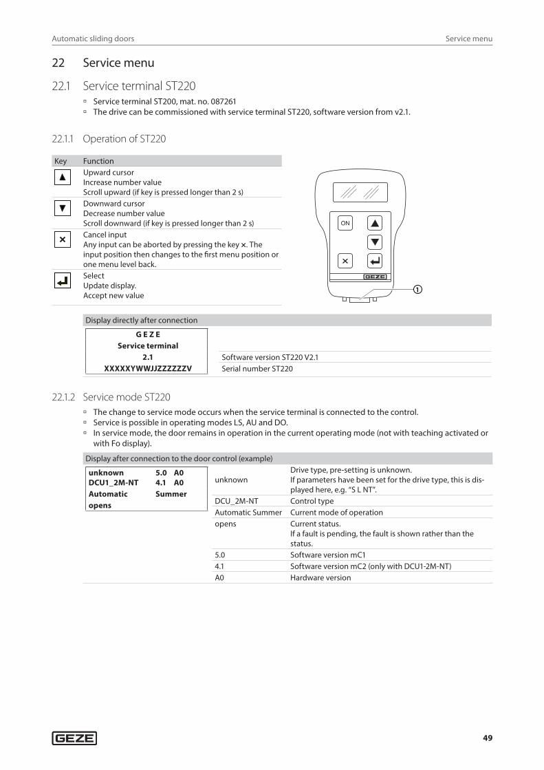
Automatic sliding doors
49
Service menu
22 Service menu
22.1 Service terminal ST220 à Service terminal ST200, mat. no. 087261 à The drive can be commissioned with service terminal ST220, software version from v2.1.
22.1.1 Operation of ST220
Key FunctionUpward cursorIncrease number valueScroll upward (if key is pressed longer than 2 s)
1
Downward cursorDecrease number value Scroll downward (if key is pressed longer than 2 s)
Cancel inputAny input can be aborted by pressing the key ×. The input position then changes to the first menu position or one menu level back.SelectUpdate display.Accept new value
Display directly after connection
G E Z EService terminal
2.1XXXXXYWWJJZZZZZZV
Software version ST220 V2.1Serial number ST220
22.1.2 Service mode ST220 à The change to service mode occurs when the service terminal is connected to the control. à Service is possible in operating modes LS, AU and DO. à In service mode, the door remains in operation in the current operating mode (not with teaching activated or
with Fo display).
Display after connection to the door control (example)
unknown 5.0 A0DCU1_2M-NT 4.1 A0Automatic Summeropens
unknownDrive type, pre-setting is unknown.If parameters have been set for the drive type, this is dis-played here, e.g. “S L NT”.
DCU_2M-NT Control typeAutomatic Summer Current mode of operationopens Current status.
If a fault is pending, the fault is shown rather than the status.
5.0 Software version mC14.1 Software version mC2 (only with DCU1-2M-NT)A0 Hardware version
Automatic sliding doors
50
Service menu
22.1.3 Password prompt ST220If a password has been assigned in the menu “Diagnosis”, “Change password”, “Service 1”, this is requested before the service menu can be entered.
Password0---*
X Enter the 4-digit password comprising figures and letters (0 … 9, A … Z, a … z) using the keys and . The position to be entered is indicated in the line below by the * symbol.
X Confirm entered position and change to next position using the key. X Cancel entry using the key × . X After entering the password, confirm by pressing the key.
22.1.4 Service menu ST220
Mode of operation
Designation Setting values Explanation
Mode of operation OFFNight modeExit onlyAutomaticHold open
OFFNight modeExit onlyAutomaticHold open
Current operating mode is displayed and can be changed.If an MPS is connected, it is not possible to change the operating mode via the ST220.
Season SummerWinter
SummerWinter
Full opening widthReduced opening width
Open doors - Key
Door parameters
Designation Setting values Explanation
Number of leaves Close on one sideClose centrally
Close on one sideClose centrally
–
Drive type UnknownSlimdrive SCSlimdrive SFSlimdrive SLSlimdrive SL NTSlimdrive SL BOSlimdrive SL CO48Slimdrive SLTSlimdrive SLVECdriveECdrive CO48Powerdrive PLECdrive BOTSA 360NT BOPowerdrive PL CO48Slimdrive SL NT-CO48Slimdrive SLT-CO48ECdrive T2ECdrive T2-CO48
UnknownSlimdrive SCSlimdrive SFSlimdrive SLSlimdrive SL NT
Slimdrive SLTSlimdrive SLVECdrive
Powerdrive PL
ECdrive T2
–
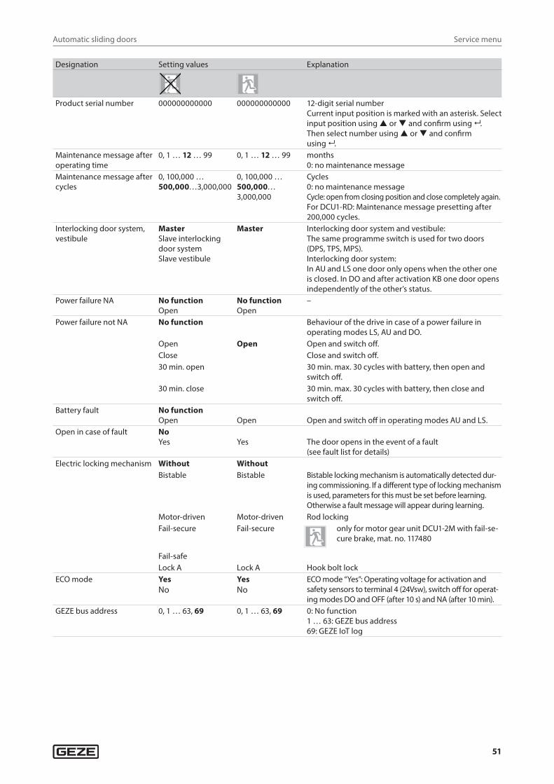
Automatic sliding doors
51
Service menu
Designation Setting values Explanation
Product serial number 000000000000 000000000000 12-digit serial numberCurrent input position is marked with an asterisk. Select input position using or and confirm using .Then select number using or and confirm using .
Maintenance message after operating time
0, 1 … 12 … 99 0, 1 … 12 … 99 months0: no maintenance message
Maintenance message after cycles
0, 100,000 … 500,000…3,000,000
0, 100,000 … 500,000… 3,000,000
Cycles0: no maintenance messageCycle: open from closing position and close completely again.For DCU1-RD: Maintenance message presetting after 200,000 cycles.
Interlocking door system, vestibule
MasterSlave interlocking door systemSlave vestibule
Master Interlocking door system and vestibule:The same programme switch is used for two doors (DPS, TPS, MPS).Interlocking door system:In AU and LS one door only opens when the other one is closed. In DO and after activation KB one door opens independently of the other’s status.
Power failure NA No functionOpen
No functionOpen
–
Power failure not NA No function Behaviour of the drive in case of a power failure in operating modes LS, AU and DO.
Open Open Open and switch off.Close Close and switch off.30 min. open 30 min. max. 30 cycles with battery, then open and
switch off.30 min. close 30 min. max. 30 cycles with battery, then close and
switch off.Battery fault No function
Open Open Open and switch off in operating modes AU and LS.Open in case of fault No
Yes Yes The door opens in the event of a fault(see fault list for details)
Electric locking mechanism Without WithoutBistable Bistable Bistable locking mechanism is automatically detected dur-
ing commissioning. If a different type of locking mechanism is used, parameters for this must be set before learning. Otherwise a fault message will appear during learning.
Motor-driven Motor-driven Rod lockingFail-secure Fail-secure only for motor gear unit DCU1-2M with fail-se-
cure brake, mat. no. 117480
Fail-safeLock A Lock A Hook bolt lock
ECO mode YesNo
YesNo
ECO mode “Yes”: Operating voltage for activation and safety sensors to terminal 4 (24Vsw), switch off for operat-ing modes DO and OFF (after 10 s) and NA (after 10 min).
GEZE bus address 0, 1 … 63, 69 0, 1 … 63, 69 0: No function1 … 63: GEZE bus address69: GEZE IoT log
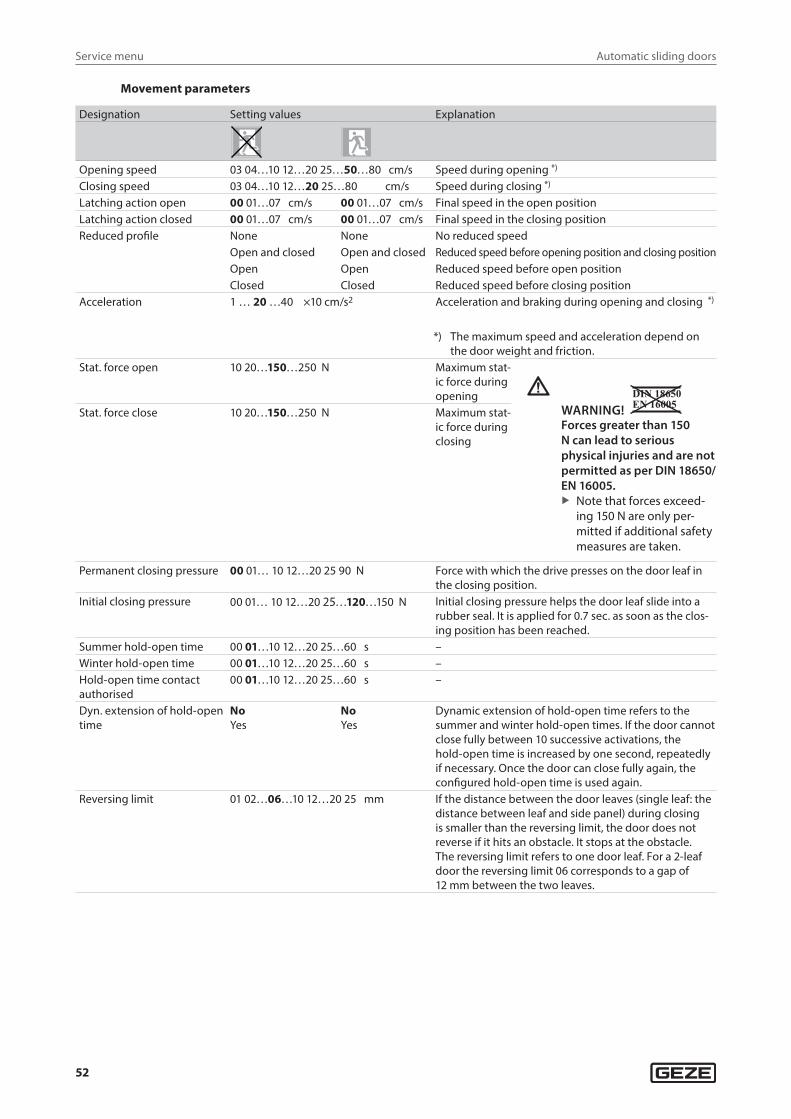
Automatic sliding doors
52
Service menu
Movement parameters
Designation Setting values Explanation
Opening speed 03 04…10 12…20 25…50…80 cm/s Speed during opening *)
Closing speed 03 04…10 12…20 25…80 cm/s Speed during closing *)
Latching action open 00 01…07 cm/s 00 01…07 cm/s Final speed in the open positionLatching action closed 00 01…07 cm/s 00 01…07 cm/s Final speed in the closing positionReduced profile None None No reduced speed
Open and closed Open and closed Reduced speed before opening position and closing positionOpen Open Reduced speed before open positionClosed Closed Reduced speed before closing position
Acceleration 1 … 20 …40 ×10 cm/s2 Acceleration and braking during opening and closing *)
*) The maximum speed and acceleration depend on the door weight and friction.
Stat. force open 10 20…150…250 N Maximum stat-ic force during opening
WARNING! Forces greater than 150 N can lead to serious physical injuries and are not permitted as per DIN 18650/EN 16005.
X Note that forces exceed-ing 150 N are only per-mitted if additional safety measures are taken.
Stat. force close 10 20…150…250 N Maximum stat-ic force during closing
Permanent closing pressure 00 01… 10 12…20 25 90 N Force with which the drive presses on the door leaf in the closing position.
Initial closing pressure 00 01… 10 12…20 25…120…150 N Initial closing pressure helps the door leaf slide into a rubber seal. It is applied for 0.7 sec. as soon as the clos-ing position has been reached.
Summer hold-open time 00 01…10 12…20 25…60 s –Winter hold-open time 00 01…10 12…20 25…60 s –Hold-open time contact authorised
00 01…10 12…20 25…60 s –
Dyn. extension of hold-open time
NoYes
NoYes
Dynamic extension of hold-open time refers to the summer and winter hold-open times. If the door cannot close fully between 10 successive activations, the hold-open time is increased by one second, repeatedly if necessary. Once the door can close fully again, the configured hold-open time is used again.
Reversing limit 01 02…06…10 12…20 25 mm If the distance between the door leaves (single leaf: the distance between leaf and side panel) during closing is smaller than the reversing limit, the door does not reverse if it hits an obstacle. It stops at the obstacle.The reversing limit refers to one door leaf. For a 2-leaf door the reversing limit 06 corresponds to a gap of 12 mm between the two leaves.
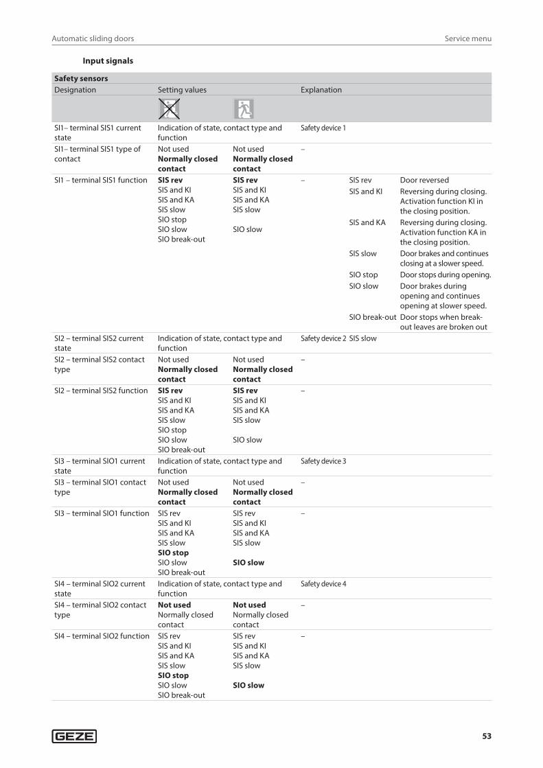
Automatic sliding doors
53
Service menu
Input signals
Safety sensorsDesignation Setting values Explanation
SI1– terminal SIS1 current state
Indication of state, contact type and function
Safety device 1
SI1– terminal SIS1 type of contact
Not usedNormally closed contact
Not usedNormally closed contact
–
SI1 – terminal SIS1 function SIS revSIS and KISIS and KASIS slowSIO stopSIO slowSIO break-out
SIS revSIS and KISIS and KASIS slow
SIO slow
– SIS rev Door reversedSIS and KI Reversing during closing.
Activation function KI in the closing position.
SIS and KA Reversing during closing. Activation function KA in the closing position.
SIS slow Door brakes and continues closing at a slower speed.
SIO stop Door stops during opening.SIO slow Door brakes during
opening and continues opening at slower speed.
SIO break-out Door stops when break-out leaves are broken out
SI2 – terminal SIS2 current state
Indication of state, contact type and function
Safety device 2 SIS slow
SI2 – terminal SIS2 contact type
Not usedNormally closed contact
Not usedNormally closed contact
–
SI2 – terminal SIS2 function SIS revSIS and KISIS and KASIS slowSIO stopSIO slowSIO break-out
SIS revSIS and KISIS and KASIS slow
SIO slow
–
SI3 – terminal SIO1 current state
Indication of state, contact type and function
Safety device 3
SI3 – terminal SIO1 contact type
Not usedNormally closed contact
Not usedNormally closed contact
–
SI3 – terminal SIO1 function SIS revSIS and KISIS and KASIS slowSIO stopSIO slowSIO break-out
SIS revSIS and KISIS and KASIS slow
SIO slow
–
SI4 – terminal SIO2 current state
Indication of state, contact type and function
Safety device 4
SI4 – terminal SIO2 contact type
Not usedNormally closed contact
Not usedNormally closed contact
–
SI4 – terminal SIO2 function SIS revSIS and KISIS and KASIS slowSIO stopSIO slowSIO break-out
SIS revSIS and KISIS and KASIS slow
SIO slow
–
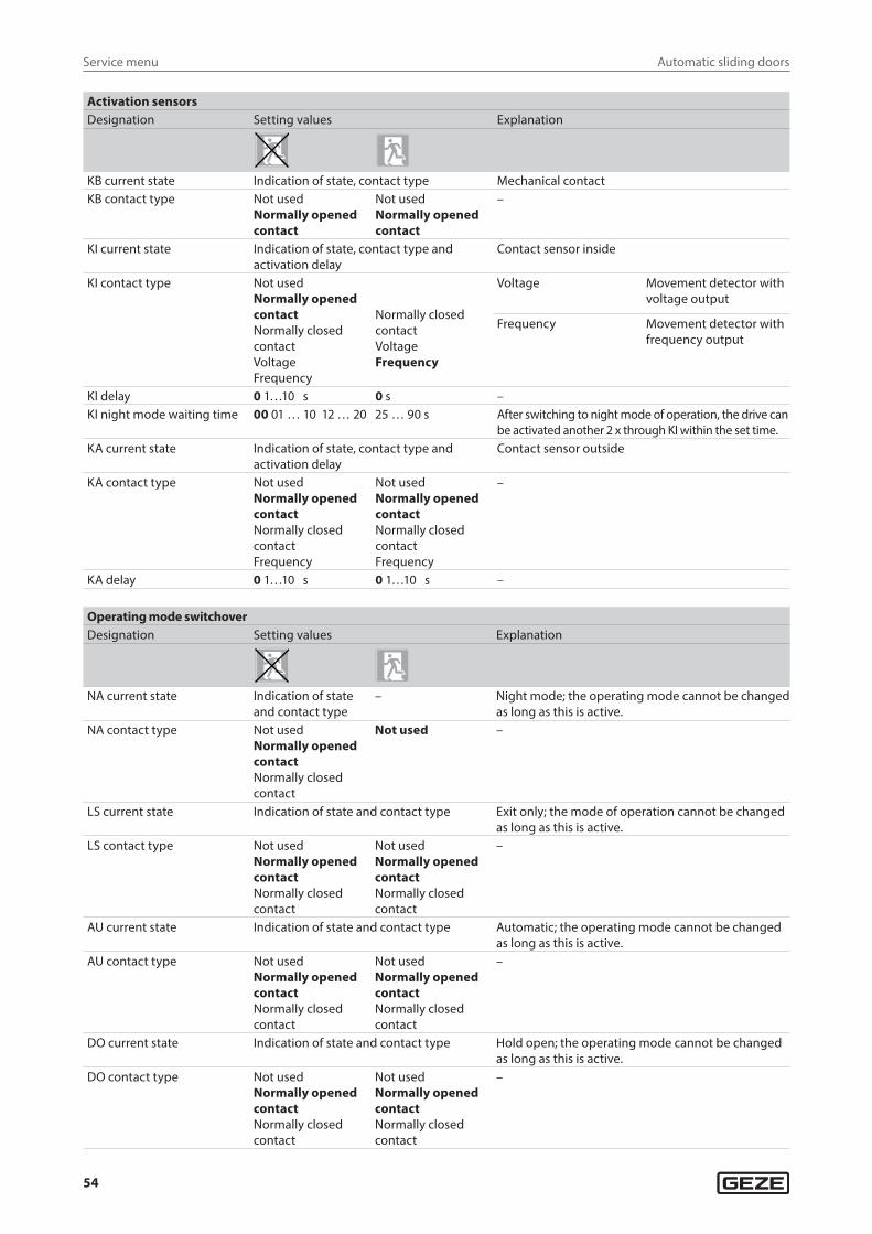
Automatic sliding doors
54
Service menu
Activation sensorsDesignation Setting values Explanation
KB current state Indication of state, contact type Mechanical contactKB contact type Not used
Normally opened contact
Not usedNormally opened contact
–
KI current state Indication of state, contact type and activation delay
Contact sensor inside
KI contact type Not usedNormally opened contactNormally closed contactVoltageFrequency
Normally closed contactVoltageFrequency
Voltage Movement detector with voltage output
Frequency Movement detector with frequency output
KI delay 0 1…10 s 0 s –KI night mode waiting time 00 01 … 10 12 … 20 25 … 90 s After switching to night mode of operation, the drive can
be activated another 2 x through KI within the set time.KA current state Indication of state, contact type and
activation delayContact sensor outside
KA contact type Not usedNormally opened contactNormally closed contactFrequency
Not usedNormally opened contactNormally closed contactFrequency
–
KA delay 0 1…10 s 0 1…10 s –
Operating mode switchoverDesignation Setting values Explanation
NA current state Indication of state and contact type
– Night mode; the operating mode cannot be changed as long as this is active.
NA contact type Not usedNormally opened contactNormally closed contact
Not used –
LS current state Indication of state and contact type Exit only; the mode of operation cannot be changed as long as this is active.
LS contact type Not usedNormally opened contactNormally closed contact
Not usedNormally opened contactNormally closed contact
–
AU current state Indication of state and contact type Automatic; the operating mode cannot be changed as long as this is active.
AU contact type Not usedNormally opened contactNormally closed contact
Not usedNormally opened contactNormally closed contact
–
DO current state Indication of state and contact type Hold open; the operating mode cannot be changed as long as this is active.
DO contact type Not usedNormally opened contactNormally closed contact
Not usedNormally opened contactNormally closed contact
–
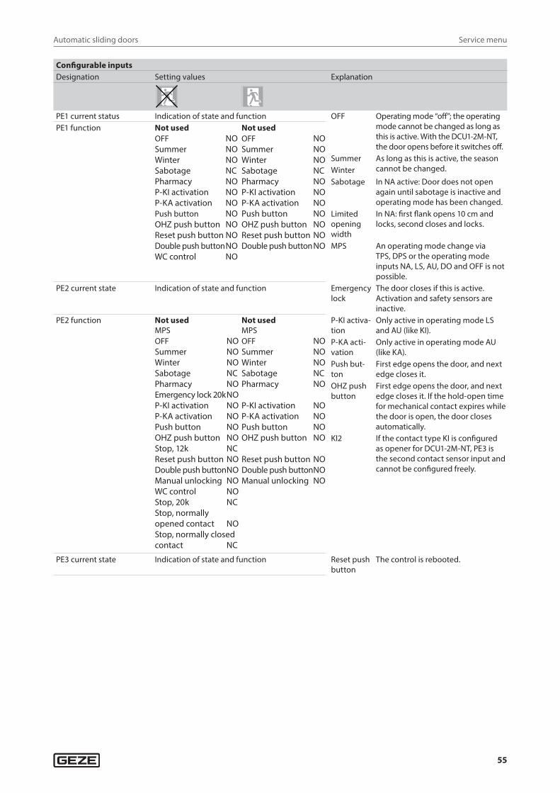
Automatic sliding doors
55
Service menu
Configurable inputsDesignation Setting values Explanation
PE1 current status Indication of state and function OFF Operating mode “off”; the operating mode cannot be changed as long as this is active. With the DCU1-2M-NT, the door opens before it switches off.
PE1 function Not usedOFF NOSummer NOWinter NOSabotage NCPharmacy NOP-KI activation NOP-KA activation NOPush button NOOHZ push button NOReset push button NODouble push button NOWC control NO
Not usedOFF NOSummer NOWinter NOSabotage NCPharmacy NOP-KI activation NOP-KA activation NOPush button NOOHZ push button NOReset push button NODouble push button NO
Summer As long as this is active, the season cannot be changed.Winter
Sabotage In NA active: Door does not open again until sabotage is inactive and operating mode has been changed.
Limited opening width
In NA: first flank opens 10 cm and locks, second closes and locks.
MPS An operating mode change via TPS, DPS or the operating mode inputs NA, LS, AU, DO and OFF is not possible.
PE2 current state Indication of state and function Emergency lock
The door closes if this is active. Activation and safety sensors are inactive.
PE2 function Not usedMPSOFF NOSummer NOWinter NOSabotage NCPharmacy NOEmergency lock 20k NOP-KI activation NOP-KA activation NOPush button NOOHZ push button NOStop, 12k NCReset push button NODouble push button NOManual unlocking NOWC control NOStop, 20k NCStop, normally opened contact NOStop, normally closed contact NC
Not usedMPSOFF NOSummer NOWinter NOSabotage NCPharmacy NO
P-KI activation NOP-KA activation NOPush button NOOHZ push button NO
Reset push button NODouble push button NOManual unlocking NO
P-KI activa-tion
Only active in operating mode LS and AU (like KI).
P-KA acti-vation
Only active in operating mode AU (like KA).
Push but-ton
First edge opens the door, and next edge closes it.
OHZ push button
First edge opens the door, and next edge closes it. If the hold-open time for mechanical contact expires while the door is open, the door closes automatically.
KI2 If the contact type KI is configured as opener for DCU1-2M-NT, PE3 is the second contact sensor input and cannot be configured freely.
PE3 current state Indication of state and function Reset push button
The control is rebooted.
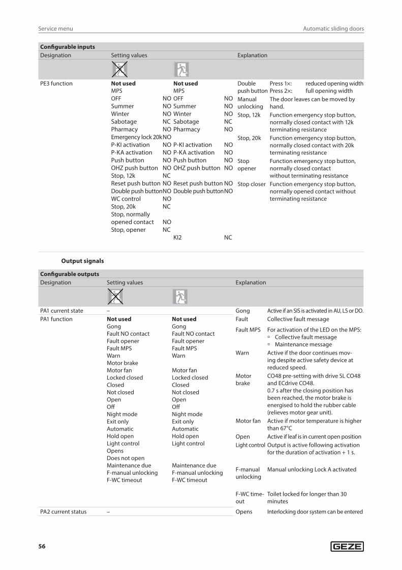
Automatic sliding doors
56
Service menu
Configurable inputsDesignation Setting values Explanation
PE3 function Not usedMPSOFF NOSummer NOWinter NOSabotage NCPharmacy NOEmergency lock 20k NOP-KI activation NOP-KA activation NOPush button NOOHZ push button NOStop, 12k NCReset push button NODouble push button NOWC control NOStop, 20k NCStop, normally opened contact NOStop, opener NC
Not usedMPSOFF NOSummer NOWinter NOSabotage NCPharmacy NO
P-KI activation NOP-KA activation NOPush button NOOHZ push button NO
Reset push button NODouble push button NO
KI2 NC
Double push button
Press 1×: reduced opening widthPress 2×: full opening width
Manual unlocking
The door leaves can be moved by hand.
Stop, 12k Function emergency stop button, normally closed contact with 12k terminating resistance
Stop, 20k Function emergency stop button, normally closed contact with 20k terminating resistance
Stop opener
Function emergency stop button, normally closed contact without terminating resistance
Stop closer Function emergency stop button, normally opened contact without terminating resistance
Output signals
Configurable outputsDesignation Setting values Explanation
PA1 current state – Gong Active if an SIS is activated in AU, LS or DO.PA1 function Not used
GongFault NO contactFault openerFault MPSWarnMotor brakeMotor fanLocked closedClosedNot closedOpenOffNight modeExit onlyAutomaticHold openLight controlOpens Does not openMaintenance dueF-manual unlockingF-WC timeout
Not usedGongFault NO contactFault openerFault MPSWarn
Motor fanLocked closedClosedNot closedOpenOffNight modeExit onlyAutomaticHold openLight control
Maintenance dueF-manual unlockingF-WC timeout
Fault Collective fault message
Fault MPS For activation of the LED on the MPS: à Collective fault message à Maintenance message
Warn Active if the door continues mov-ing despite active safety device at reduced speed.
Motor brake
CO48 pre-setting with drive SL CO48 and ECdrive CO48.0.7 s after the closing position has been reached, the motor brake is energised to hold the rubber cable (relieves motor gear unit).
Motor fan Active if motor temperature is higher than 67°C
Open Active if leaf is in current open positionLight control Output is active following activation
for the duration of activation + 1 s.
F-manual unlocking
Manual unlocking Lock A activated
F-WC time-out
Toilet locked for longer than 30 minutes
PA2 current status – Opens Interlocking door system can be entered
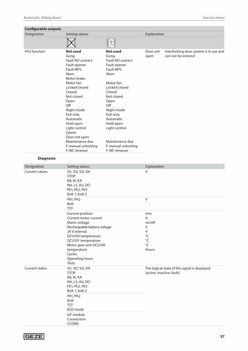
Automatic sliding doors
57
Service menu
Configurable outputsDesignation Setting values Explanation
PA2 function Not usedGongFault NO contactFault openerFault MPSWarnMotor brakeMotor fanLocked closedClosedNot closedOpenOffNight modeExit onlyAutomaticHold openLight controlOpens Does not openMaintenance dueF-manual unlockingF-WC timeout
Not usedGongFault NO contactFault openerFault MPSWarn
Motor fanLocked closedClosedNot closedOpenOffNight modeExit onlyAutomaticHold openLight control
Maintenance dueF-manual unlockingF-WC timeout
Does not open
Interlocking door system is in use and can not be entered
Diagnosis
Designation Setting values ExplanationCurrent values SI1, SI2, SI3, SI4
STOPKB, KI, KANA, LS, AU, DOPE1, PE2, PE3Bolt 1, bolt 2
V
PA1, PA2BoltTST
V
Current positionCurrent motor currentMains voltageRechargeable battery voltage24 V internalDCU100 temperatureDCU101 temperatureMotor gear unit DCU100 temperatureCycles Operating hoursTests
mmAon/offVV°C°C°CHours
Current states SI1, SI2, SI3, SI4STOPKB, KI, KANA, LS, AU, DOPE1, PE2, PE3Bolt 1, bolt 2
The logical state of the signal is displayed (active, inactive, fault).
PA1, PA2BoltTSTECO modeIoT moduleConnectionCCDMS
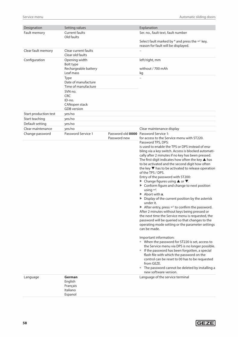
Automatic sliding doors
58
Service menu
Designation Setting values ExplanationFault memory Current faults
Old faultsSer. no., fault text, fault number
Select fault marked by * and press the key, reason for fault will be displayed.
Clear fault memory Clear current faultsClear old faults
–
Configuration Opening widthBolt typeRechargeable batteryLeaf mass
left/right, mm
without / 700 mAhkg
TypeDate of manufactureTime of manufacture
–
SVN no.CRCID-no.CANopen stackGDB version
Start production test yes/noStart teaching yes/noDefault setting yes/noClear maintenance yes/no Clear maintenance displayChange password Password Service 1 Password old 0000
Password newPassword Service 1:for access to the Service menu with ST220.Password TPS, DPS: is used to enable the TPS or DPS instead of ena-bling via a key switch. Access is blocked automati-cally after 2 minutes if no key has been pressed.The first digit indicates how often the key has to be activated and the second digit how often the key has to be activated to release operation of the TPS / DPS.Entry of the password with ST200:
X Change figures using or . X Conform figure and change to next position
using . X Abort with x. X Display of the current position by the asterisk
under it. X After entry, press to confirm the password.
After 2 minutes without keys being pressed or the next time the Service menu is requested, the password will be queried so that changes to the operating mode setting or the parameter settings can be made.
Important information: à When the password for ST220 is set, access to
the Service menu via DPS is no longer possible. à If the password has been forgotten, a special
flash file with which the password on the control can be reset to 00 has to be requested from GEZE.
à The password cannot be deleted by installing a new software version.
Language GermanEnglishFrançaisItalianoEspanol
Language of the service terminal
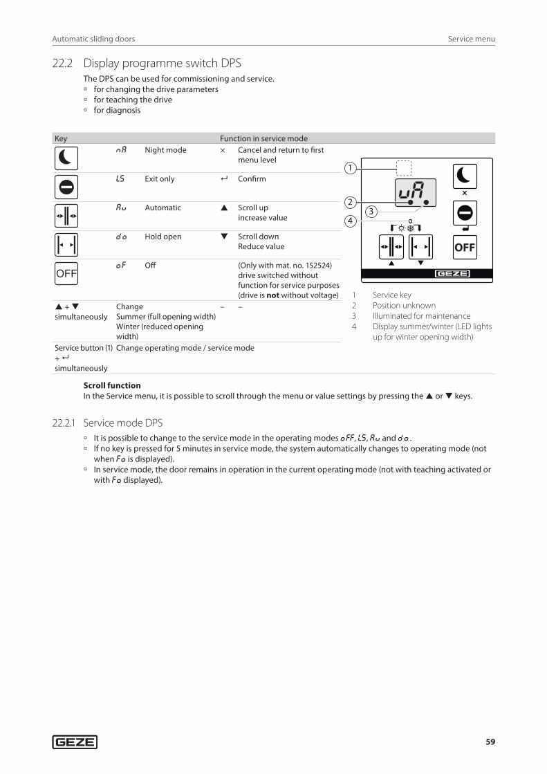
Automatic sliding doors
59
Service menu
22.2 Display programme switch DPSThe DPS can be used for commissioning and service. à for changing the drive parameters à for teaching the drive à for diagnosis
Key Function in service modeNa Night mode × Cancel and return to first
menu level
OFF
1
23
4
1 Service key2 Position unknown3 Illuminated for maintenance4 Display summer/winter (LED lights
up for winter opening width)
ls Exit only Confirm
aU Automatic Scroll up increase value
DO Hold open Scroll down Reduce value
OFFOf Off (Only with mat. no. 152524)
drive switched without function for service purposes (drive is not without voltage)
+ simultaneously
ChangeSummer (full opening width)Winter (reduced opening width)
– –
Service button (1) + simultaneously
Change operating mode / service mode
Scroll functionIn the Service menu, it is possible to scroll through the menu or value settings by pressing the or keys.
22.2.1 Service mode DPS à It is possible to change to the service mode in the operating modes Off, ls, aU and DO . à If no key is pressed for 5 minutes in service mode, the system automatically changes to operating mode (not
when fO is displayed). à In service mode, the door remains in operation in the current operating mode (not with teaching activated or
with fO displayed).
Automatic sliding doors
60
Service menu
22.2.2 Service menu DPS
1. Menu
Display Explanation Setting valuesUo Opening speed 03 04…10 12…20 25…50 80 cm/s *)
Uc Closing speed 03 04…10 12…20 25…50 80 cm/s *)
so Latching action open 00 01…07 cm/ssc Latching action closed 00 01…07 cm/s DCU1-RD: 1 … 10 … 14Oh Summer hold-open time 00 01…10 12…20 25…60 sO® Winter hold-open time (reduced opening width) 00 01…10 12…20 25…60 sOs Hold-open time contact authorised 00 01…10 12…20 25…60 sOD Dynamic extension of the hold-open time 00 no
01 yesBo Acceleration 1…10 12…20 25…40 × 10 cm/s2 *)
(multiply value displayed by 10)U ® Reduced profile 00 no reduced speed
01 reduced speed before opening position and before closing position
02 reduced speed before open position03 reduced speed before closing position
fo Static force open 01 10 15 20 25 × 10 N(multiply value displayed by 10)
WARNING!Forces greater than 150 N can lead to serious physical injuries and are not permitted as per DIN 18650/EN 16005.
X Note that forces exceeding 150 N are only permitted if additional safety measures are taken.
fc Static force closed 01 10 15 20 25 × 10 N(multiply value displayed by 10)
cf Permanent closing pressure 00 01… 10 12…20 25…50 60…90 cl Reversing limit 01 02…06…10 12…20 25 mmNe Switch to the 2nd menu –
*) The maximum speed and acceleration depend on the door weight and friction.
Automatic sliding doors
61
Service menu
2. Menu
Display Explanation Setting values
s1 Safety 1 contact type (terminal SIS1) 0002
Not usedNormally closed contact
0002
Not usedNormally closed contact
f1 Safety 1 function (terminal SIS1) 01020304050607
SIS revSIS and KISIS and KASIS slowSIO stopSIO slowSIO break-out
01020304
06
SIS revSIS and KISIS and KASIS slow
SIO slow
s2 Safety 2 contact type (terminal SIS2) 0002
Not usedNormally closed contact
0002
Not usedNormally closed contact
f2 Safety 2 function (terminal SIS2) 01020304050607
SIS revSIS and KISIS and KASIS slowSIO stopSIO slowSIO break-out
01020304
06
SIS revSIS and KISIS and KASIS slow
SIO slow
s3 Safety 3 contact type (terminal SIO1) 0002
Not usedNormally closed contact
0002
Not usedNormally closed contact
f3 Safety 3 function (terminal SIO1) 01020304050607
SIS revSIS and KISIS and KASIS slowSIO stopSIO slowSIO break-out
01020304
06
SIS revSIS and KISIS and KASIS slow
SIO slow
s4 Safety 4 contact type (terminal SIO2) 0002
Not usedNormally closed contact
0002
Not usedNormally closed contact
f4 Safety 4 function (terminal SIO2) 01020304050607
SIS revSIS and KISIS and KASIS slowSIO stopSIO slowSIO break-out
01020304
06
SIS revSIS and KISIS and KASIS slow
SIO slow
cB Mechanical contact, contact type 0001
Not usedNormally opened contact
0001
Not usedNormally opened contact
cI Contact sensor inside contact type 0001020304
Not usedNormally opened contactNormally closed contactVoltageFrequency
020304
Redundant normally closed contactVoltageFrequency
aI Contact sensor inside activation delay 00 01 … 10 s 00NT KI Night mode waiting time 00 01 … 10 12 … 20 25 … 90 s After switching to night
mode of operation, the drive can be activated another 2 x through KI within the set time.
cO Contact sensor outside contact type 000102
04
Not usedNormally opened contactNormally closed contact
Frequency
000102
04
Not usedNormally opened contactNormally closed contact
Frequencyaa Contact sensor outside activation delay 00 10 s 00 10 s
Automatic sliding doors
62
Service menu
Display Explanation Setting values
e1 Configurable input 1 00
020304050608091011
131421
Not used
Operating mode OFF NOSummer NOWinter NOSabotage NCPharmacy NOP-KI activation NOP-KA activation NOSwitch function NOSwitch function, close after Os NOReset push button NODouble push button NOWC control NO
00
020304050608091011
1314
Not used
Operating mode OFF NOSummer NOWinter NOSabotage NCPharmacy NOP-KI activation NOP-KA activation NOSwitch function NOSwitch function, close after Os NOReset push button NODouble push button NO
e2 Configurable input 2 000102030405060708091011
1213142021232425
Not usedMPSOperating mode OFF NOSummer NOWinter NOSabotage NCPharmacy NOEmergency lock NOP-KI activation NOP-KA activation NOSwitch function NOSwitch function, close after Os NOSTOP 12kReset push button NODouble push button NOManual unlocking NOWC control NOSTOP 20k NCSTOP closer NOSTOP opener NC
00010203040506
08091011
131420
Not usedMPSOperating mode OFF NOSummer NOWinter NOSabotage NCPharmacy NO
P-KI activation NOP-KA activation NOSwitch function NOSwitch function, close after Os NO
Reset push button NODouble push button NOManual unlocking NO
e3 Configurable input 3 000102030405060708091011
12131421
232425
Not usedMPS Operating mode OFF NOSummer NOWinter NOSabotage NCPharmacy NOEmergency lock NOP-KI activation NOP-KA activation NOSwitch function NOSwitch function, close after Os NOSTOP 12kReset push button NODouble push button NOWC control NO
STOP 20k NCSTOP closer NOSTOP opener NC
00010203040506
08091011
1314
22
Not usedMPS Operating mode OFF NOSummer NOWinter NOSabotage NCPharmacy NO
P-KI activation NOP-KA activation NOSwitch function NOSwitch function; close after Os NO
Reset push button NODouble push button NO
Contact sensor inside 2 NC
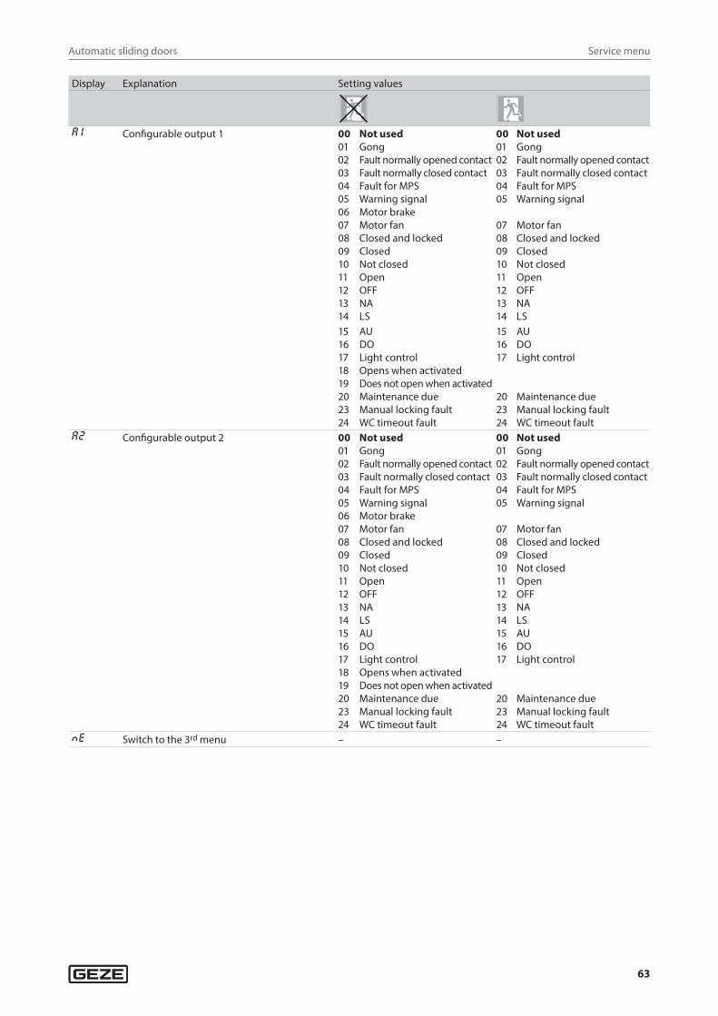
Automatic sliding doors
63
Service menu
Display Explanation Setting values
a1 Configurable output 1 000102030405060708091011121314
Not usedGongFault normally opened contactFault normally closed contactFault for MPSWarning signalMotor brakeMotor fanClosed and lockedClosedNot closedOpenOFFNALS
000102030405
0708091011121314
Not usedGongFault normally opened contactFault normally closed contactFault for MPSWarning signal
Motor fanClosed and lockedClosedNot closedOpenOFFNALS
1516171819202324
AUDOLight controlOpens when activatedDoes not open when activatedMaintenance dueManual locking faultWC timeout fault
151617
202324
AUDOLight control
Maintenance dueManual locking faultWC timeout fault
a2 Configurable output 2 0001020304050607080910111213141516171819202324
Not usedGongFault normally opened contactFault normally closed contactFault for MPSWarning signalMotor brakeMotor fanClosed and lockedClosedNot closedOpenOFFNALSAUDOLight controlOpens when activatedDoes not open when activatedMaintenance dueManual locking faultWC timeout fault
000102030405
0708091011121314151617
202324
Not usedGongFault normally opened contactFault normally closed contactFault for MPSWarning signal
Motor fanClosed and lockedClosedNot closedOpenOFFNALSAUDOLight control
Maintenance dueManual locking faultWC timeout fault
Ne Switch to the 3rd menu – –
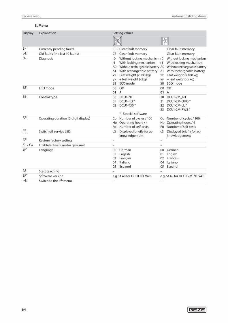
Automatic sliding doors
64
Service menu
3. Menu
Display Explanation Setting values
e® Currently pending faults CE Clear fault memory Clear fault memoryOe Old faults (the last 10 faults) CE Clear fault memory Clear fault memoryD I Diagnosis r0
r1A0A1xxyyS8
Without locking mechanismWith locking mechanismWithout rechargeable batteryWith rechargeable batteryLeaf weight (x 100 kg)+ leaf weight (x kg)ECO mode
r0r1A0A1xxyyS8
Without locking mechanismWith locking mechanismWithout rechargeable batteryWith rechargeable batteryLeaf weight (x 100 kg)+ leaf weight (x kg)ECO mode
sb ECO mode 0001
OffA
0001
OffA
sT Control type 000102
DCU1-NTDCU1-RD *DCU1-T30 *
* Special software
20212223
DCU1-2M_NTDCU1-2M-DUO *DCU1-2M-LL *DCU1-2M-RWS *
sa Operating duration (6-digit display) CoHoFo
Number of cycles / 100Operating hours / 4Number of self-tests
CoHoFo
Number of cycles / 100Operating hours / 4Number of self-tests
cs Switch off service LED cS Displayed briefly for ac-knowledgement
cS Displayed briefly for ac-knowledgement
cp Restore factory setting – –f® / fO Enable/activate motor gear unit – –sp Language 00
01020405
GermanEnglishFrançaisItalianoEspanol
0001020405
GermanEnglishFrançaisItalianoEspanol
le Start teaching – –ep Software version e.g. St 40 for DCU1-NT V4.0 e.g. St 40 for DCU1-2M-NT V4.0Ne Switch to the 4th menu – –
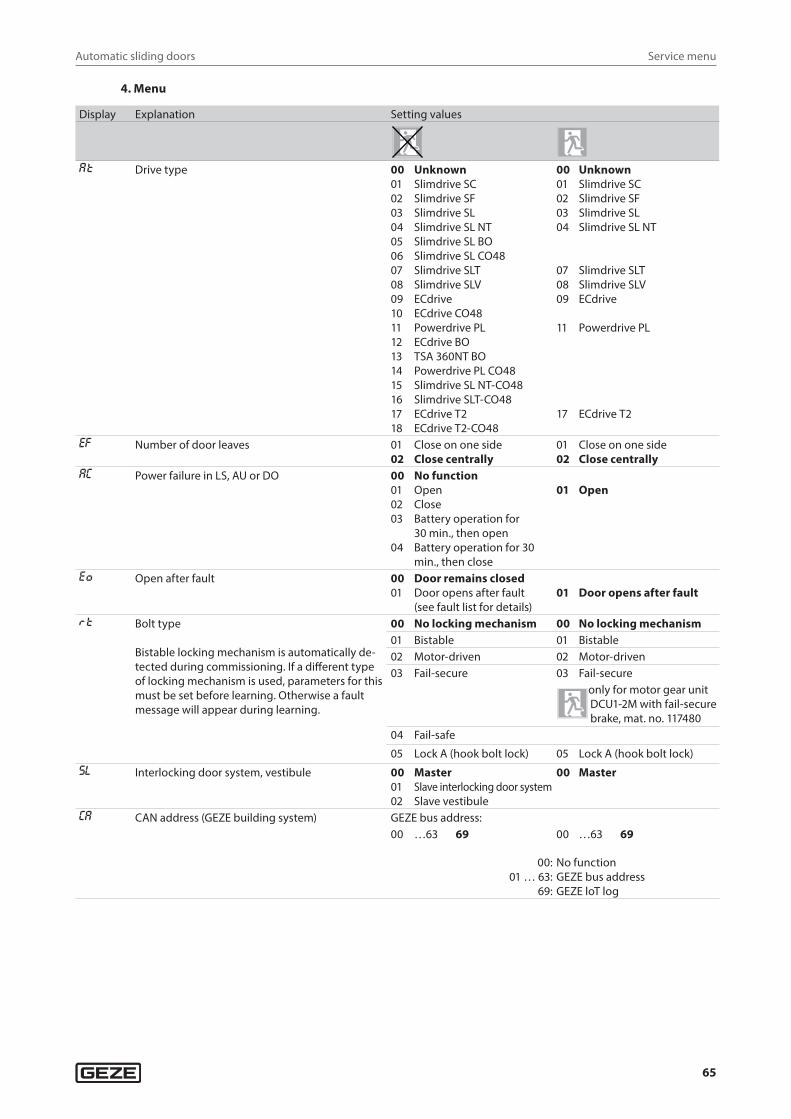
Automatic sliding doors
65
Service menu
4. Menu
Display Explanation Setting values
aT Drive type 00010203040506070809101112131415161718
UnknownSlimdrive SCSlimdrive SFSlimdrive SLSlimdrive SL NTSlimdrive SL BOSlimdrive SL CO48Slimdrive SLTSlimdrive SLVECdriveECdrive CO48Powerdrive PLECdrive BOTSA 360NT BOPowerdrive PL CO48Slimdrive SL NT-CO48Slimdrive SLT-CO48ECdrive T2ECdrive T2-CO48
0001020304
070809
11
17
UnknownSlimdrive SCSlimdrive SFSlimdrive SLSlimdrive SL NT
Slimdrive SLTSlimdrive SLVECdrive
Powerdrive PL
ECdrive T2
ef Number of door leaves 0102
Close on one sideClose centrally
0102
Close on one sideClose centrally
ac Power failure in LS, AU or DO 00010203
04
No functionOpenCloseBattery operation for 30 min., then openBattery operation for 30 min., then close
01 Open
eO Open after fault 0001
Door remains closedDoor opens after fault (see fault list for details)
01 Door opens after fault
®T Bolt type
Bistable locking mechanism is automatically de-tected during commissioning. If a different type of locking mechanism is used, parameters for this must be set before learning. Otherwise a fault message will appear during learning.
00 No locking mechanism 00 No locking mechanism01 Bistable 01 Bistable02 Motor-driven 02 Motor-driven03 Fail-secure 03 Fail-secure
only for motor gear unit DCU1-2M with fail-secure brake, mat. no. 117480
04 Fail-safe
05 Lock A (hook bolt lock) 05 Lock A (hook bolt lock)sl Interlocking door system, vestibule 00
0102
MasterSlave interlocking door systemSlave vestibule
00 Master
ca CAN address (GEZE building system) GEZE bus address:00 …63 69 00 …63 69
00:01 … 63:
69:
No functionGEZE bus addressGEZE loT log
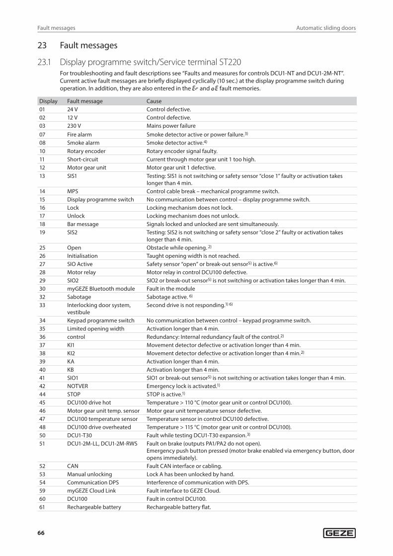
Automatic sliding doors
66
Fault messages
23 Fault messages
23.1 Display programme switch/Service terminal ST220For troubleshooting and fault descriptions see “Faults and measures for controls DCU1-NT and DCU1-2M-NT”.Current active fault messages are briefly displayed cyclically (10 sec.) at the display programme switch during operation. In addition, they are also entered in the e® and Oe fault memories.
Display Fault message Cause01 24 V Control defective.02 12 V Control defective.03 230 V Mains power failure07 Fire alarm Smoke detector active or power failure.3)
08 Smoke alarm Smoke detector active.4)
10 Rotary encoder Rotary encoder signal faulty.11 Short-circuit Current through motor gear unit 1 too high.12 Motor gear unit Motor gear unit 1 defective.13 SIS1 Testing: SIS1 is not switching or safety sensor “close 1” faulty or activation takes
longer than 4 min.14 MPS Control cable break – mechanical programme switch.15 Display programme switch No communication between control – display programme switch.16 Lock Locking mechanism does not lock.17 Unlock Locking mechanism does not unlock.18 Bar message Signals locked and unlocked are sent simultaneously.19 SIS2 Testing: SIS2 is not switching or safety sensor “close 2” faulty or activation takes
longer than 4 min.25 Open Obstacle while opening. 2)
26 Initialisation Taught opening width is not reached.27 SIO Active Safety sensor “open” or break-out sensor5) is active.6)
28 Motor relay Motor relay in control DCU100 defective.29 SIO2 SIO2 or break-out sensor5) is not switching or activation takes longer than 4 min.30 myGEZE Bluetooth module Fault in the module32 Sabotage Sabotage active. 6)
33 Interlocking door system, vestibule
Second drive is not responding.1) 6)
34 Keypad programme switch No communication between control – keypad programme switch.35 Limited opening width Activation longer than 4 min.36 control Redundancy: Internal redundancy fault of the control.2)
37 KI1 Movement detector defective or activation longer than 4 min.38 KI2 Movement detector defective or activation longer than 4 min.2)
39 KA Activation longer than 4 min.40 KB Activation longer than 4 min.41 SIO1 SIO1 or break-out sensor5) is not switching or activation takes longer than 4 min.42 NOTVER Emergency lock is activated.1)
44 STOP STOP is active.1)
45 DCU100 drive hot Temperature > 110 °C (motor gear unit or control DCU100).46 Motor gear unit temp. sensor Motor gear unit temperature sensor defective.47 DCU100 temperature sensor Temperature sensor in control DCU100 defective.48 DCU100 drive overheated Temperature > 115 °C (motor gear unit or control DCU100).50 DCU1-T30 Fault while testing DCU1-T30 expansion.3)
51 DCU1-2M-LL, DCU1-2M-RWS Fault on brake (outputs PA1/PA2 do not open).Emergency push button pressed (motor brake enabled via emergency button, door opens immediately).
52 CAN Fault CAN interface or cabling.53 Manual unlocking Lock A has been unlocked by hand.54 Communication DPS Interference of communication with DPS.59 myGEZE Cloud Link Fault interface to GEZE Cloud.60 DCU100 Fault in control DCU100.61 Rechargeable battery Rechargeable battery flat.
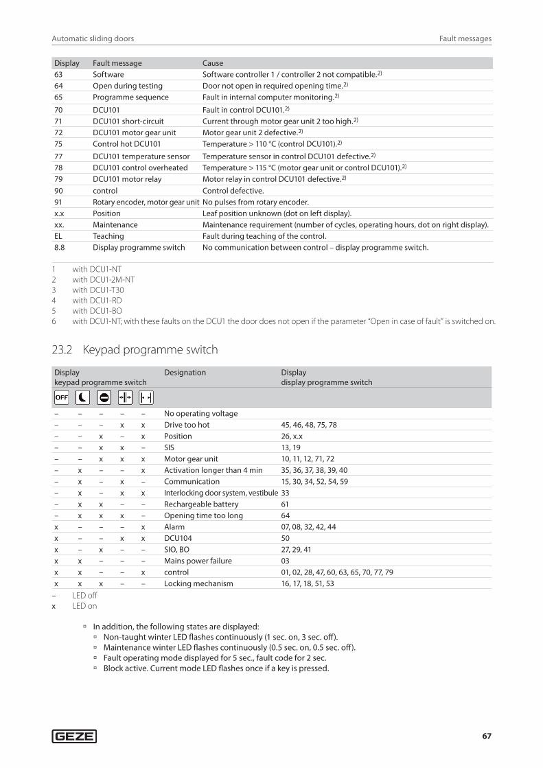
Automatic sliding doors
67
Fault messages
Display Fault message Cause63 Software Software controller 1 / controller 2 not compatible.2)
64 Open during testing Door not open in required opening time.2)
65 Programme sequence Fault in internal computer monitoring.2)
70 DCU101 Fault in control DCU101.2)
71 DCU101 short-circuit Current through motor gear unit 2 too high.2)
72 DCU101 motor gear unit Motor gear unit 2 defective.2)
75 Control hot DCU101 Temperature > 110 °C (control DCU101).2)
77 DCU101 temperature sensor Temperature sensor in control DCU101 defective.2)
78 DCU101 control overheated Temperature > 115 °C (motor gear unit or control DCU101).2)
79 DCU101 motor relay Motor relay in control DCU101 defective.2)
90 control Control defective.91 Rotary encoder, motor gear unit No pulses from rotary encoder.x.x Position Leaf position unknown (dot on left display).xx. Maintenance Maintenance requirement (number of cycles, operating hours, dot on right display).EL Teaching Fault during teaching of the control.8.8 Display programme switch No communication between control – display programme switch.
1 with DCU1-NT2 with DCU1-2M-NT3 with DCU1-T304 with DCU1-RD5 with DCU1-BO6 with DCU1-NT; with these faults on the DCU1 the door does not open if the parameter “Open in case of fault” is switched on.
23.2 Keypad programme switch
Display keypad programme switch
Designation Display display programme switch
– – – – – No operating voltage– – – x x Drive too hot 45, 46, 48, 75, 78– – x – x Position 26, x.x– – x x – SIS 13, 19– – x x x Motor gear unit 10, 11, 12, 71, 72– x – – x Activation longer than 4 min 35, 36, 37, 38, 39, 40– x – x – Communication 15, 30, 34, 52, 54, 59– x – x x Interlocking door system, vestibule 33– x x – – Rechargeable battery 61– x x x – Opening time too long 64x – – – x Alarm 07, 08, 32, 42, 44x – – x x DCU104 50x – x – – SIO, BO 27, 29, 41x x – – – Mains power failure 03x x – – x control 01, 02, 28, 47, 60, 63, 65, 70, 77, 79x x x – – Locking mechanism 16, 17, 18, 51, 53
– LED offx LED on
à In addition, the following states are displayed: à Non-taught winter LED flashes continuously (1 sec. on, 3 sec. off). à Maintenance winter LED flashes continuously (0.5 sec. on, 0.5 sec. off). à Fault operating mode displayed for 5 sec., fault code for 2 sec. à Block active. Current mode LED flashes once if a key is pressed.
GermanyGEZE GmbHNiederlassung Süd-WestTel. +49 (0) 7152 203 594E-Mail: [email protected]
GEZE GmbHNiederlassung Süd-OstTel. +49 (0) 7152 203 6440E-Mail: [email protected]
GEZE GmbHNiederlassung OstTel. +49 (0) 7152 203 6840E-Mail: [email protected]
GEZE GmbHNiederlassung Mitte/LuxemburgTel. +49 (0) 7152 203 6888E-Mail: [email protected]
GEZE GmbHNiederlassung WestTel. +49 (0) 7152 203 6770 E-Mail: [email protected]
GEZE GmbHNiederlassung NordTel. +49 (0) 7152 203 6600E-Mail: [email protected]
GEZE Service GmbHTel. +49 (0) 1802 923392E-Mail: [email protected]
AustriaGEZE AustriaE-Mail: [email protected]
Baltic States –Lithuania / Latvia / EstoniaE-Mail: [email protected]
BeneluxGEZE Benelux B.V.E-Mail: [email protected]
BulgariaGEZE Bulgaria - Trade E-Mail: [email protected]
ChinaGEZE Industries (Tianjin) Co., Ltd.E-Mail: [email protected]
GEZE Industries (Tianjin) Co., Ltd.Branch Office ShanghaiE-Mail: [email protected]
GEZE Industries (Tianjin) Co., Ltd.Branch Office GuangzhouE-Mail: [email protected]
GEZE Industries (Tianjin) Co., Ltd.Branch Office BeijingE-Mail: [email protected]
FranceGEZE France S.A.R.L.E-Mail: [email protected]
HungaryGEZE Hungary Kft.E-Mail: [email protected]
IberiaGEZE Iberia S.R.L.E-Mail: [email protected]
IndiaGEZE India Private Ltd.E-Mail: [email protected]
ItalyGEZE Italia S.r.lE-Mail: [email protected]
GEZE Engineering Roma S.r.lE-Mail: [email protected]
KoreaGEZE Korea Ltd.E-Mail: [email protected]
PolandGEZE Polska Sp.z o.o.E-Mail: [email protected]
RomaniaGEZE Romania S.R.L.E-Mail: [email protected]
RussiaOOO GEZE RUSE-Mail: [email protected]
Scandinavia – SwedenGEZE Scandinavia ABE-Mail: [email protected]
Scandinavia – NorwayGEZE Scandinavia AB avd. NorgeE-Mail: [email protected]
Scandinavia – DenmarkGEZE DanmarkE-Mail: [email protected]
SingaporeGEZE (Asia Pacific) Pte, Ltd.E-Mail: [email protected]
South AfricaGEZE South Africa (Pty) Ltd.E-Mail: [email protected]
SwitzerlandGEZE Schweiz AGE-Mail: [email protected]
TurkeyGEZE Kapı ve Pencere SistemleriE-Mail: [email protected]
UkraineLLC GEZE UkraineE-Mail: [email protected]
United Arab Emirates/GCCGEZE Middle EastE-Mail: [email protected]
United KingdomGEZE UK Ltd.E-Mail: [email protected]
GEZE GmbHReinhold-Vöster-Straße 21–2971229 LeonbergGermany
Tel.: 0049 7152 203 0Fax.: 0049 7152 203 310www.geze.com