Automatic Shifting Bike Description and Build...
32
1 Design Details Our design project is a bicycle that shifts gears automatically based on several inputs; these inputs are rear wheel speed, pedaling direction, and initial chain position. This is accomplished by utilizing the factory derailleur/cable system but with hightorque servo motors operating them instead of handturned levers. The bicycle uses 4 PIC microcontrollers to process the inputs, control the shifting, and display information to the user. The microcontroller programs were written using PicBasic Pro, and compiled with the Melabs U2 Programmer 4.40 (Refer to Bill of Materials). The control box houses an LCD display which shows current speed and gear information, and notifies the rider when a shift is occurring. The keypad below the display is used to enter the initial chain position so that the servos can move to the appropriate location before operating the bike. Also found on the control box is a toggle switch used to supply batter power to the entire system, and a buzzer that sounds during shifts (Refer to Figure 1 component 1). One servo motor controls the position of the derailleur for the pedal sprockets (2); the other servo motor controls the position of the derailleur for the wheel sprockets (3). The appropriate position is determined based on wheel speed information received from the speed sensor circuit (5). The speed sensor circuit is in constant communication with the control box, so that current speed information can be displayed to the user at all times (6). The shaft encoder (4) tells the control box (1) if the pedals are rotating forward, in reverse, or not rotating. Regardless of speed and current gear, the control box (1) will prevent the servos (2,3) from moving if the shaft encoder (4) detects that the pedals are not rotating or are rotating backward. If the rider is pedaling forward, then the servos (2, 3) will shift the gears of the bicycle to a comfortable gear ratio with respect to the current speed. 1 6 5 3 4 2 Figure 1 Overview picture of bicycle
Transcript of Automatic Shifting Bike Description and Build...

1
Design Details
Our design project is a bicycle that shifts gears automatically based on several inputs; these inputs are rear wheel speed, pedaling direction, and initial chain position. This is accomplished by utilizing the factory derailleur/cable
system but with high-‐torque servo motors operating them instead of hand-‐turned levers. The bicycle uses 4 PIC microcontrollers to process the inputs, control the shifting, and display information to the user. The microcontroller programs were written using PicBasic Pro, and compiled with the Melabs U2 Programmer 4.40 (Refer to Bill of
Materials). The control box houses an LCD display which shows current speed and gear information, and notifies the rider when a shift is occurring. The keypad below the display is used to enter the initial chain position so that the servos can move to the appropriate location before operating the bike. Also found on the control box is a toggle switch used to
supply batter power to the entire system, and a buzzer that sounds during shifts (Refer to Figure 1 component 1). One servo motor controls the position of the derailleur for the pedal sprockets (2); the other servo motor controls the position of the derailleur for the wheel sprockets (3). The appropriate position is determined based on wheel speed
information received from the speed sensor circuit (5). The speed sensor circuit is in constant communication with the control box, so that current speed information can be displayed to the user at all times (6). The shaft encoder (4) tells the control box (1) if the pedals are rotating forward, in reverse, or not rotating. Regardless of speed and current gear,
the control box (1) will prevent the servos (2,3) from moving if the shaft encoder (4) detects that the pedals are not rotating or are rotating backward. If the rider is pedaling forward, then the servos (2, 3) will shift the gears of the bicycle to a comfortable gear ratio with respect to the current speed.
1
6
5
3
4 2
Figure 1-‐ Overview picture of bicycle

2
Figure 2 -‐ Speed Sensor & Related Components
1.) Speed Measurement (Note: all component numbers refer to Figure 2)
To measure the speed of the rear wheel, our sensor of choice was an LED-‐phototransistor pair (1) [note that this component cannot be seen in the photo on the left as it is mounted on the opposite side of the circuit board]; this is
manufactured as a single unit, with both components mounted on a common plane, and an open-‐collector output to which a pull-‐up resistor is connected. When light from the LED is reflected back to the phototransistor, the transistor turns on and pulls the output voltage low. At all other times, the transistor is in cutoff (resembles an open circuit) and
the output voltage is pulled high by the pull-‐up resistor.
Many small strips of reflective tape (2) are placed around the rear wheel’s outer perimeter, all at an equal radius. The sensor is mounted at that same radius, in close proximity to the strips of tape. Thus, as the wheel rotates, the sensor outputs a train of pulses as the phototransistor is repeatedly switched on and off by the bursts of reflected
LED light. The number of pulses generated in one revolution of the wheel is, of course, equal to the number of strips of reflective tape.
Since the raw output of the sensor is not discrete (the output merely approaches 0V as a reflective object is brought closer), the signal must pass through a Schmitt trigger (3) before being sent to the PIC. This ensures a clean,
rectangular (digital) waveform whose transitions can be recognized easily. Also, the sensitivity of the sensor (i.e. how close the reflective tape needs to be in order to turn on the transistor) was found to be adjustable, and proportional to the value of the variable pull-‐up resistor (4) connected at the sensor’s output. This is presumably because a transistor is
essentially a current amplifier; by increasing the resistance in the collector circuit, less base current (or in this case, LED light) is required to drive the transistor into its saturation region. Therefore, the final resistance value we chose was not arbitrary; rather, it is the optimal value which produce reliable pulses from wheel rotation while remaining unaffected
by ambient light.
Having conditioned the sensor output into an appropriate form, the last step is converting that output into a numerical speed (in miles per hour). This function is performed by a PIC devoted to the speed sensor subsystem (hereinafter referred to as PIC #4, in accordance with the convention established on our wiring diagram). PIC #4 counts
the number of pulses received from the speed sensor within a short period of time (we found an appropriate interval to be 0.25 sec.). This count is then converted to a speed in mph using the following formula:
1 2
3
4

3
€
speedmph =pulses0.25sec
×1rev
60pulses×80inrev
×1mi
63,360in×3600sechr
Here the parameters that must be known are pulses per revolution (number of strips of reflective tape) and the distance
per revolution (wheel circumference). The above calculation is performed at the end of every 0.25 sec sampling interval, after which it is sent to other subsystems as they require it.
This process of counting pulses, converting them to speed, and communicating the speed to other PICs requires the full attention of PIC #4 at all times; no other tasks can be performed while the PIC is counting pulses. Because of
this, we found it necessary to devote an entire PIC to the task of managing the speed sensor and its surrounding assembly. In fact, a dedicated PIC turned out to be necessary for most of our key components in this project
Figure 3 -‐ Servos
2.) Gear Shifting (Note: all component numbers refer to Figure 3)
To accomplish the function of automatic shifting, two high-‐torque RC servo motors (1,2) are used. As is the case
on most modern bicycles, there are two sets of gears to be shifted: one located on the pedals, and the other on the rear wheel. Since ours is a 15-‐speed bike, these gear sets each contain 3 and 5 gears, respectively. To interface the gear sets with the servos, a pulley (3) is attached to each servo. Around each pulley is wrapped one of the bicycle’s original shift
cables (4); of course, the choice between the two shift cables determines which gear set is controlled by that particular servo. With this arrangement, we were able to retain most of the bicycle’s original shifting hardware; it was only necessary to remove the portion of the system from the shift cables up to the handlebars, where the manual shifting
1 2
3 4

4
equipment was formerly located. Shifting gears is accomplished by indexing each servo to the appropriate position, which then pulls the shift cable by the exact amount needed to shift to the desired gear.
Each RC servo is moved through its range of motion by a single digital control signal (power and ground
connections are also required). The servo’s position is determined by the duty cycle of that control signal. Therefore, any time a servo is sent a signal of a known duty cycle, the position of the servo will also be known; these servos have an internal feedback system which ensures this is always the case. All we had to do was experimentally determine the duty
cycle (or equivalently pulse width, since the control signal is of a constant frequency) needed to move each servo to the positions corresponding to every available gear on its associated gear set. This was done using the following circuit:
Figure 4 -‐ Servo Test Circuit
The circuit in Fig. 4 consists of a dual NAND switch debounce circuit (1) and a “one-‐shot” 555 timer circuit (2). When the push button is depressed, a single pulse is sent out on the output pin of the 555. The length of the pulse is set
using a 100k trim pot, and can be adjusted until the appropriate pulse length is found for each gear. We found these servos to be unique in that the digital controller on board each servo will read a control pulse length, store it, move the servo head to the corresponding position, and actively hold that position for approximately 1.5 seconds. Therefore, we
had some liberty in how often we needed to send a pulse to each servo. The servos were also found to have an initialization period in which they require approximately 15 pulses on the signal line before being capable of normal operation. This requires knowing which gear the bike is in upon system power-‐up, so that the initialization pulses do not
1
2

5
inadvertently shift the bicycle to a new gear. We will send this initial gear information serially to PIC #2 from another PIC, as will be explained in a later section.
Having found the pulse widths corresponding to all possible gears, the overall gear settings of the bicycle can
then be adjusted or maintained by varying the pulse width of each servo’s control signal among these experimentally determined values. The values are different for each servo (i.e. gear 3 on the pedals requires a different pulse width than gear 3 on the wheel) due to the dynamic differences between the two gear sets, as well as manufacturing
variability which causes the two servo motors (despite both being the same model) to behave slightly differently. Also, in general a different pulse width is required to upshift into a certain gear versus downshifting into that same gear.
To perform all of this control signal manipulation, another PIC microcontroller is utilized (this one will be referred to as PIC #2). As mentioned before, the first function PIC #2 performs is receiving the initial gear values (this
only occurs once, upon power-‐on). Then, PIC #2 enters its main program loop. Its first task in that loop is to receive the current speed of the bicycle from PIC #4. Next, a sequence of logic is executed which compares the speed to the current gear and determines whether or not that gear is ideal. The principle is that each gear on the bicycle has a “comfortable”
speed range associated with it; when the speed comes to be above or below the limits of that range, the bicycle should respectively upshift or downshift. The logic in PIC #2 has a separate section corresponding to each gear. Within each section, the speed is compared to a different range, and action is taken based on the result of that comparison.
In order to elaborate further, it is necessary to divulge the information structures used by PIC #2 to shift and
maintain gears. Since the PIC must keep track of the bicycle’s current gear at all times, the gear settings are stored numerically in a variable called “gear” and updated each time a shift occurs. Although there are really two separate gear settings (one for each gear set), they are stored and manipulated as a single base-‐ten number for convenience’s sake.
For example, gear 3 on the pedals and gear 2 on the wheel corresponds to “gear = 32”. Also, the pulse widths required by each servo to maintain a certain gear setting are stored using a pair of variables, one for each servo/gearset. These
variables are called “T1_high” and “T2_high”.
Each time the logic in PIC #2 determines that a shift is needed, the three variables mentioned above are all updated to reflect the gear which is being shifted into. Also, a shift-‐indicator line connected to PIC #1 (which has not yet been discussed) is set high, as a means of communicating that a shift is about to occur. This interface will be explained
in a following section, but suffice it to say that the purpose is to give the rider a cue that the bike is shifting. Finally, the PIC sends out a pulse of width “T1_high” to servo 1, and a pulse of width “T2_high” to servo 2, thus shifting the bicycle to the new gear. This is the end of the PIC #2 program loop, after which it returns to the beginning and repeats all of
these functions.
The next time through the loop, PIC #2 will find that the current gear is now appropriate for the speed, and no shift will occur. Thus, the variables “gear”, “T1_high” and “T2_high” will remain at their previous values. The servos will again be sent pulses; since the lengths of these pulses will not have changed, the current gear will be held until it is
necessary to shift once more. As was the case for the speed sensor, it should be apparent that this shifting functionality could not have been accomplished with anything less than a single dedicated PIC; not only do the servos require a relatively continuous stream of pulses, but the speed-‐to-‐gear comparisons must be done often in order to ensure that
the bike is adequately responsive.

6
Figure 5 -‐ Shaft Encoder
3.) Directional Sensing of Pedal Rotation (Note: all component numbers refer to Figure 5)
The preceding discussion of the conditions under which a shift will occur is, admittedly, not entirely complete. At first glance it may seem that the current speed and gear should be the sole determining factors of whether or not to
shift. However, there is one additional element which cannot be ignored in the design of a practical automatic-‐shifting bike, and that is pedal rotation. If the bicycle attempts to shift while the rider is not pedaling (or even worse, pedaling backward), chain misalignment will almost certainly occur, requiring the rider to dismount and reset the entire system.
Therefore, a crucial component of our project is a subsystem which determines the current condition of the pedals at all times: forward motion, backward motion, or no motion.
The heart of this subsystem is an absolute rotary encoder, whose two digital outputs (1,2) assume four different states per revolution of its shaft (3); the encoder is driven by the pedals via a belt drive system (4). When the state
changes, the direction of pedal rotation can be ascertained by comparing the new state to the previous state. The pedals can be assumed stationary if the state does not change for a certain amount of time. To execute this logic, an additional PIC (PIC #3) was added to our design. Once again, the use of a dedicated PIC is justified by the all-‐consuming
nature of this task. It is impossible to do anything else while continuously analyzing the states of the shaft encoder.
PIC #3 runs in a short main program loop, within which it remains until the shaft encoder changes state and triggers an interrupt. The main loop first reads the two shaft encoder outputs and stores their current state in two variables, then executes a very short pause. Both of these instructions are enclosed within a “for” loop, and will repeat a
number of times determined by the maximum value of the counter variable (which is specified within the “for” loop initialization). Since reading the state of the shaft encoder takes under a microsecond, the execution time of a single iteration of the “for” loop is determined almost entirely by the length of the pause. As such, the time it takes the entire
main loop to execute can be considered equal to the length of the pause multiplied by the maximum value of the counter variable.
1 2
3
4

7
With this simple main program (and without yet analyzing the states of the shaft encoder), we are equipped to detect the presence or absence of pedal rotation. Since the main program loop will continue to execute until the shaft
encoder changes state, we can use the total length of time the main loop takes to execute as the “time-‐out” period; if no encoder motion occurs within this period, the pedals can be judged to be stationary. As discussed above, the “time-‐out” period can be controlled by adjusting both the length of the pause and the maximum value of the “for” loop’s counter
variable; we found 0.5 seconds to be the optimal time-‐out period. The instruction following the “for” loop is one which sets a “shift-‐enable” line low. This line is connected to PIC #2, and is the only interface PIC #3 has with any of the other PIC’s. PIC #2 will not perform any of its speed-‐gear comparisons unless this line is high (this is accomplished by enclosing
the comparisons within an “if (shift-‐enable == 1)” statement). Therefore, if the shift-‐enable line is low, PIC #2 cannot shift gears, since there is no other section of the program in which T1_high and T2_high (see the preceding section) can be changed. However, PIC #2 will still send out pulses to the servos in order to maintain the current gear settings.
Of course, if the shaft encoder does change state within the 0.5 second time-‐out period, then the “shift-‐enable”
line is not set low, because an interrupt will occur before that instruction is reached. Upon being interrupted, the program finishes execution of its current instruction, then immediately branches to the interrupt service routine. The interrupt service routine first reads the new state of the shaft encoder; the fact that an interrupt occurs guarantees that
this will be different from the old state which was being continuously read in by the main program. Then, the new state is compared to the old state; although the necessary code is lengthy, the concept is simple. For any of the four possible “new” states, there are two values which the previous state could have been (assuming a state is never skipped, which
we found to be a reasonable assumption). One of those values corresponds to forward rotation, and the other to backward rotation. For forward rotation, the shift-‐enable line is set high; for backward rotation, it is set low. The final task of the interrupt service routine is to reset the counter variable used in the main program loop. That way, when
program control is returned to the main loop, the whole process starts over again.
Figure 6 -‐ User Interface Components (Outside of Control Box)
4.) Display and User Interface (Note: all component numbers refer to Figure 6)
1
2 3
5 6 7 8
9

8
Thus far, only the core operation of our system has been discussed, with no attention paid to how it interacts with the user. However, a major component of our project is the control box, which contains an LCD screen (1), keypad
(2), and buzzer (3) for user interface. The control box also contains all four PIC’s (4-‐8) and all other project circuitry. The keypad is used only once, upon system power-‐on, to input the initial gear settings of the bicycle. This is necessary because the system “forgets” what gear it is in when turned off, and so a new reference point for the shifting maps must
be established (a.k.a. the initial gear must be input) every time the system is turned on. We contemplated storing the gear settings in flash memory instead, but decided against it. With our method, should any type of mechanical or electrical malfunction occur, the system can easily be reset and started in any desired gear setup.
The fourth PIC in our design (referred to as PIC #1) manages the LCD display, keypad, and buzzer. Immediately
after system power-‐on, PIC #1’s program displays a message on the LCD prompting the user to enter the first gear (this corresponds to the gear set located on the pedals). It then receives this gear value serially from a keypad encoder IC (9), whose row and column lines are connected directly to the keypad. This greatly reduces the I/O requirements on PIC #1,
since the keypad encoder needs only one line to communicate the value of the pressed key to the PIC; without this component, the seven row and column lines from the keypad would need to be connected directly to the PIC, and additional programming would be required to continuously scan the keypad.
Once PIC #1 receives the first key press value, it checks the value for validity. If the received value does not
correspond to one of the possible choices for that gear set (the only options in this case are 1, 2, and 3), the LCD will inform the user that an invalid gear was selected, and the user will be re-‐prompted to enter the first gear. The same will happen if any key outside the range 1 through 5 is pressed when prompted for the second gear. Since the data from the
keypad encoder will be in ASCII form rather than decimal (e.g. $30 = 0, $31 = 1, etc.), each value must be converted upon receipt by the PIC; then, the two gear settings are combined and stored in a variable called “gear”, much like in the PIC #2 program.
PIC #1 now needs to send PIC #2 the initial gear settings so that PIC #2 can initialize the servos to the correct gears. This communication is performed using a standard serial interface with a separate handshake line, a method which is widely used throughout our project. The technical details of this interface are beyond the scope of this
discussion, but are well documented in the commented code provided. After PIC #1 has sent the initial gear settings, it enters into its main program loop. This loop alternately displays current gear and speed information on the LCD display, switching from one to the other about every 2.5 seconds. The speed is refreshed 10 times within these few seconds as
new serial data is provided from PIC #4, so the speed information is always very up-‐to-‐date. On the other hand, the current gear settings are only received once prior to their 2.5 second display, and do not need to be refreshed during this period. This is because an interrupt will occur whenever the gears are shifted.
In the previous section concerning the Gear Shifting subsystem, it was mentioned that PIC #2 sets a shift-‐
indicator line high when a shift is occurring. This line is connected to PIC #1 and is used to trigger an interrupt, the purpose of which is to alert the rider that the bicycle is shifting. As such, the first instruction in the interrupt service routine outputs the message “Now Shifting” to the LCD display. Then, a piezoelectric buzzer is activated in such a way
that it plays a short musical phrase. The details of this are worth elaborating on briefly.
When a digital signal of a certain frequency is applied to our buzzer, it produces a tone of that same frequency. Thus, by varying the signal’s frequency between frequencies which correspond to certain musical notes, it is possible to generate music with the buzzer. Within PIC #1’s interrupt service routine, there is a short subroutine which plays a note
for a preset (short) duration of time by toggling the buzzer between high and low a certain number of times. The length of time the buzzer is high (or low) is determined by the variable “note”, which then also defines the frequency of the

9
tone emitted by the buzzer. The variable “note” can be redefined prior to each subroutine call so that a different tone is produced each time; using this technique, we configured the buzzer to play a series of arpeggios (which are notes of a
chord played in rapid succession rather than simultaneously) of a short chord progression: C major / A minor / D minor / G major / C major. This entire process takes less than a second, after which the interrupt service routine ends and control is returned to the main program.
Construction Instructions
Servo Mounting Tray The mounting tray for the servos was constructed using a plate of 3/16” 6061-‐T6 aluminum bar. Slots for the servos
were milled out of this piece to a depth of approximately 1/8”. This was sufficient to prevent the servo from moving in the direction of the cable tension. Two stiffeners in the form of aluminum angle were riveted to the bottom of the 3/16” plate to strengthen it after the removal of more than half its thickness in the servo slots. Two holes were then
drilled in the center of the 3/16” plate in locations which corresponded to the pre-‐existing threaded holes on the bicycle frame originally intended to mount the water bottle holder. Dimensions for these holes will vary depending on the bicycle being used and will need to be measured. In order to hold the servos down, slots were cut in the aluminum
angle stiffeners directly below each servo mounting slot to allow steel wire to be wrapped around the body of the servo as the servo itself has no mounting lugs. Stainless steel aircraft safety wire was used for this application. Figure 7 shows
the mounting model for the servo motors as described above.
Shaft Encoder Mount and Drive Mechanism In order to drive the shaft encoder, a belt and pulley system was implemented. It was desired that the shaft encoder spin faster than the bicycle pedal shaft, thus the pulley attached to the pedal is twice as large as the one attached to the encoder to achieve a 2:1 gear ratio. The pulleys are custom made by welding washers together. In order to achieve a
Figure 7-‐ Servo Mounting Model

10
track for the belt to run in, a smaller diameter washer is sandwiched between two larger diameter washers. The pedal pulley is 3” in diameter, and it is bolted onto the back side of the pedal opposite of the chain sprocket assembly. The
encoder pulley is 1.5” in diameter and is welded to a shaft supported between two ball bearings. The shaft of the encoder is interfaced to the pulley shaft using a flexible rubber tube in order to accommodate any axis misalignment. The mounting framework for the pulley bearings and shaft encoder is made from 1/16” by 1/2" aluminum strip bent to
shape and riveted together. The mounting framework is attached to one of two pieces of aluminum angle which can be clamped together on either side of the bicycle frame with a central screw as can be seen in the diagrams below. Figure 8, 9, and 10 show the model of the shaft encoder mounting mechanism.
Figure 8-‐Shaft Encoder Mounting Model View 1

11
Figure 9-‐ Shaft Encoder Mounting Model View 2
Figure 10-‐ Shaft Encoder Mounting Model View 3

12
Project Box In this project, a 6x4x2 box was used to house the LCD display, the keypad, the buzzer, and the on/off switch (all of
which can be seen externally). Holes for these components were cut in the top of the box (the sizes of these holes will vary according to the specific component used). Refer to the picture of the top view of the project box to see the orientation and assembly. The copper clad circuit board (which contains the four PICs), the keypad circuit, and the
batteries were put inside the project box (which can not be seen externally). The inside components rested securely on a sheet of foam rubber to help prevent damage to the components. The project box was put on the bike’s handle bars by drilling holes in the bottom of the box and using cable ties to secure the box to the handle bars.
Circuit Boards The circuit board for the PICs, the keypad, and the speed circuit board should be designed according to the schematic/ wiring diagram provided. The circuits should be laid out with electromagnetic interference taken into account, which
means that it is important to minimize the size of the loops created by circuit wiring.
Rear Wheel Speed Sensor The speed sensor circuit (including the photo sensor, Schmitt trigger, and sensitivity potentiometer) was constructed on a separate circuit board such that it could be mounted next to the rear wheel. Three wires (power, ground, and signal)
were used to connect it to the main control circuit board. These three wires were twisted together in order to minimize electromagnetic interference issues. The photo sensor was triggered by patches of reflective tape mounted around the inner circumference of the rim of the rear wheel. The strips of tape were mounted on a ring of plywood whose outer
diameter was equal to the inner diameter of the rim. The width of the ring was 2 inches in order to accommodate a 1 inch square of tape. The ring was attached to the wheel using adhesive cable tie mounts with cable ties running through the individual spokes (as shown in Figure 11 below).
Reflective tape squares were placed around the circumference of the ring at even intervals. One square was placed in
line with each of the 36 spokes, making it easy to establish the spacing. Once the ring was attached to the wheel, the sensor circuit board was mounted on the frame of the bicycle such that the photo transistor tracked the plywood ring (as can be seen in the pictures).
Figure 11-‐Cable Tie Mounting Diagram


T:\students\UNGRAD\ME\ben1984j\shared\drop-box\PIC 1-1202 (2).pbp
' Program for PIC #1 - Display and Interface
define OSC 8OSCCON.4 = 1 : OSCCON.5 = 1 : OSCCON.6 = 1
ANSEL = 0
INTCON = $90 ' Interrupt on rising edge of RB0; thisOPTION_REG = $FF ' allows the program to deviate from ' normal operation when PIC #2 ' indicates that a shift is about to occuron interrupt goto shift_alert
speed_ser41 var PORTB.7 ' The current speed of the bike speed_hs41 var PORTB.6 ' (in mph x 10) will be received seriallyspeed var byte ' from PIC #4 (again, a handshake line ' is required in addition to the data line) ' and stored in a variable. speed_1 var byte ' It is then necessary to split the speedspeed_0 var byte ' so that the decimal part (tenths digit) ' is stored in one variable (speed_0) and ' the integer part is stored in another ' variable (speed_1). If these were not ' two separate variables, it would be ' impossible to display a decimal point ' in between them.
gear_ascii var byte ' Stores the ASCII value for each gear as ' received from the keypad encoder. These ' ASCII values will be converted to decimal ' and used to determine the initial gear ' settings.
gear var byte '"gear" is a single base-ten numbergear_1 var byte ' which contains information about the currentgear_2 var byte ' state of both gears. It is advantageous to ' combine both gears into a single number ' to simplify the serial data transfer, but for ' display on the LCD screen "gear" must be split ' into its components "gear_1" and "gear_2".
gear_ser21 var PORTB.2 ' These two pins are used to serially gear_hs21 var PORTB.1 ' transmit information from PIC #2 ' regarding what gear the bike is in. ' "gear_ser" is the data line, while ' "gear_hs" is a handshake line used ' to synchronize the serial ' communication.
key_mode con 0 ' 2400 baud serial communication is ' used for the keypad encoderser_mode con 2 ' 9600 baud serial communication is ' used for everything else
shifting_now21 var PORTB.0 ' This line will be set high by PIC #2 when ' a shift is about to occur.buzzer var PORTB.4 ' This output will be used to sound a ' buzzer which alerts the rider to an
Page 1 of 7 12/9/2011 7:47 AM

T:\students\UNGRAD\ME\ben1984j\shared\drop-box\PIC 1-1202 (2).pbp
' impending shift.key_value var PORTB.5 ' This pin is connected to the keypad ' encoder
i var byte ' These are counter variables used inj var word ' various loops throughout the program.k var byte
d7tone con 426 ' tones played by buzzerc7tone con 478b6tone con 506a6tone con 568g6tone con 638f6tone con 716e6tone con 758d6tone con 851c6tone con 956b5tone con 1012g5tone con 1276d5tone con 1703
ontime con 30 ' defines how long each tone sounds
l var word ' variables used in note play subroutinenote var word
' Main program:
disable
low gear_hs21low speed_hs41
pause 500 ' Allow LCD display to power up
enter1:lcdout $FE, 1, "Please enter the"lcdout $FE, $C0, "first gear: " ' The rider must input the initial settingsserin key_value, key_mode, gear_ascii ' of the gears every time our system is ' powered on, so that a starting point ' for the shifting maps can be established.if (gear_ascii == $31) then gear_1 = 2else if (gear_ascii == $32) then gear_1 = 3else lcdout $FE, 1, "Invalid gear." pause 1000 goto enter1endifendif
lcdout dec gear_1 pause 1000 enter2: lcdout $FE, 1, "Please enter the"
Page 2 of 7 12/9/2011 7:47 AM

T:\students\UNGRAD\ME\ben1984j\shared\drop-box\PIC 1-1202 (2).pbp
lcdout $FE, $C0, "second gear: " serin key_value, key_mode, gear_ascii if (gear_ascii == $31) then gear_2 = 2else if (gear_ascii == $34) then gear_2 = 4else if (gear_ascii == $35) then gear_2 = 5else lcdout $FE, 1, "Invalid gear." ' For both gear 1 and gear 2, only pause 1000 ' the values corresponding to gears goto enter2 ' that are actually used are allowed.endifendifendif lcdout dec gear_2 pause 1000
gear = (gear_1 * 10) + gear_2
high gear_hs21pauseus 10serout gear_ser21, ser_mode, [gear] ' sends initial gear values to PIC #2 low gear_hs21
TRISB.1 = 1 ' reconfigures gear_hs21 from outputpauseus 50 ' to input, gives PIC 2 time to do ' the opposite
lcdout $FE, 1, "Initializing"lcdout $FE, $C0, "servos…"
while (gear_hs21 == 0) ' Waits for signal from PIC #2 indicatingwend ' that servo initialization is done
pauseus 50 ' After PIC #2 has stopped using gear_hslow gear_hs21 ' as an output, set it low so PIC #2 ' won't later think PIC #1 is ready to ' receive data if it really isn'tenable main:
for i = 1 to 10 disable high speed_hs41 ' Receives current speed serin speed_ser41, ser_mode, speed ' information from PIC #4 low speed_hs41 enable
speed_1 = speed / 10 'Separates the speed into speed_0 = speed // 10 ' its integer and decimal ' components
Page 3 of 7 12/9/2011 7:47 AM

T:\students\UNGRAD\ME\ben1984j\shared\drop-box\PIC 1-1202 (2).pbp
lcdout $FE, 1, "Current speed:" ' Displays speed on screenlcdout $FE, $C0, dec speed_1, ".", dec speed_0, " mph"next i
disablehigh gear_hs21 ' Receives current gearserin gear_ser21, ser_mode, gear ' information from PIC #2low gear_hs21enable
gear_1 = gear / 10gear_2 = gear // 10lcdout $FE, 1, "Current gear:" ' Displays gear info on screenlcdout $FE, $C0, " ", dec gear_1, "-", dec gear_2 ' for 2.5 secondsfor j = 1 to 250pause 10next j
goto main
disable
shift_alert: ' When a shift is about to occur, thelcdout $FE, 1, "Now shifting" ' program breaks out of its speed/gear ' display loop and informs the user ' via a message and buzzer. After the ' shift, the program returns to its ' normal operation.
goto intmain
noteplay:for l = 1 to ontime high buzzer pauseus note low buzzer pauseus notenext lreturn
intmain:
note = c7tone ' plays a short series of musicalgosub noteplay ' arpeggiosnote = g6tonegosub noteplaynote = e6tonegosub noteplaynote = g6tonegosub noteplaynote = c7tonegosub noteplaynote = g6tonegosub noteplaynote = e6tonegosub noteplaynote = g6tone
note = c7tone
Page 4 of 7 12/9/2011 7:47 AM

T:\students\UNGRAD\ME\ben1984j\shared\drop-box\PIC 1-1202 (2).pbp
gosub noteplaynote = g6tonegosub noteplaynote = e6tonegosub noteplaynote = g6tonegosub noteplaynote = c7tonegosub noteplaynote = g6tonegosub noteplaynote = e6tonegosub noteplaynote = g6tone
note = c7tonegosub noteplaynote = a6tonegosub noteplaynote = e6tonegosub noteplaynote = a6tonegosub noteplaynote = c7tonegosub noteplaynote = a6tonegosub noteplaynote = e6tonegosub noteplaynote = a6tone
note = c7tonegosub noteplaynote = a6tonegosub noteplaynote = e6tonegosub noteplaynote = a6tonegosub noteplaynote = c7tonegosub noteplaynote = a6tonegosub noteplaynote = e6tonegosub noteplaynote = a6tone
note = d7tonegosub noteplaynote = a6tonegosub noteplaynote = f6tonegosub noteplaynote = a6tonegosub noteplaynote = d7tonegosub noteplaynote = a6tonegosub noteplaynote = f6tone
Page 5 of 7 12/9/2011 7:47 AM

T:\students\UNGRAD\ME\ben1984j\shared\drop-box\PIC 1-1202 (2).pbp
gosub noteplaynote = a6tone
note = d7tonegosub noteplaynote = a6tonegosub noteplaynote = f6tonegosub noteplaynote = a6tonegosub noteplaynote = d7tonegosub noteplaynote = a6tonegosub noteplaynote = f6tonegosub noteplaynote = a6tone
note = d7tonegosub noteplaynote = b6tonegosub noteplaynote = g6tonegosub noteplaynote = b6tonegosub noteplaynote = d7tonegosub noteplaynote = b6tonegosub noteplaynote = g6tonegosub noteplaynote = b6tone
note = d7tonegosub noteplaynote = b6tonegosub noteplaynote = g6tonegosub noteplaynote = b6tonegosub noteplaynote = d7tonegosub noteplaynote = b6tonegosub noteplaynote = g6tonegosub noteplaynote = b6tone
note = c7tonegosub noteplaynote = c7tonegosub noteplaynote = c7tonegosub noteplaynote = c7tone
INTCON.1 = 0
Page 6 of 7 12/9/2011 7:47 AM

T:\students\UNGRAD\ME\ben1984j\shared\drop-box\PIC 1-1202 (2).pbp
j = 250resume enable
end
Page 7 of 7 12/9/2011 7:47 AM

T:\students\UNGRAD\ME\ben1984j\shared\drop-box\PIC2-1203-gearchange.pbp
' Program for PIC #2-Shifting Gears w/servos
define OSC 8OSCCON.4 = 1 : OSCCON.5 = 1 : OSCCON.6 = 1ANSEL = 0
'Define Ports
gear_ser21 var PORTB.2 'Communication to PIC 1 regarding which gear_hs21 var PORTB.1 'gear PIC 2 is in (so current gear can be ' displayed on LCD screen)
shift_enable32 var PORTA.1 'From PIC 3, tells PIC 2 if pedals are moving. 'When set high, PIC 2 is allowed to shift.
shifting_now21 var PORTA.0 'Set high when a shift is about to occur. This ' line is connected to PIC #1 and allows it ' to indicate to the rider that a shift is ' happening.
Servo_1 var PORTB.7 ' Send out pulse to set angle for the servo Servo_2 var PORTB.6 ' motors 1 and 2, which are used to shift gears speed_ser42 var PORTB.5 ' Receives current speed from PIC #4 speed_hs42 var PORTB.4 ' Handshake line used to synchronize ' communication with PIC 4 'Define Variables
ser_mode con 2 ' 2400 baud mode is used for all serial ' communication
speed var byte 'Variable for current speed
gear var byte 'Variable for current geargear_1 var bytegear_2 var byte
T con 30000 ' Period of servo pulses
T1_high var word ' These variables represent the length of theT2_high var word ' pulses sent to each servo
i var byte ' Counter variables used in loops which sendj var byte ' out the initialization pulses to the servos
n1gear2t con 1067 ' Pulse widths for Servo 1 gearsn1gear3t con 1921
n2gear2t_up con 898 ' Pulse widths for Servo 2 gears n2gear2t_down con 754 n2gear4t_up con 1626n2gear4t_down con 1303n2gear5t_up con 1900
Page 1 of 5 12/9/2011 7:47 AM

T:\students\UNGRAD\ME\ben1984j\shared\drop-box\PIC2-1203-gearchange.pbp
low shifting_now21 ' Initialize output signals lowlow speed_hs42
pause 100while(gear_hs21==0)wend serin gear_ser21, ser_mode, gear ' Receive initial gear info from PIC1
pauseus 10 ' Wait for PIC 1 to stop using gear_hs21low gear_hs21 ' as output
gear_1 = gear / 10gear_2 = gear // 10
if (gear_1 == 2) then ' Set initial pulse widths for servos, based T1_high = n1gear2t ' on initial gear settingsendifif (gear_1 == 3) then T1_high = n1gear3tendif
if (gear_2 == 2) then T2_high = n2gear2t_upendifif (gear_2 == 4) then T2_high = n2gear4t_upendifif (gear_2 == 5) then T2_high = n2gear5t_upendif
for i = 1 to 15 ' Initialize servoshigh Servo_1 pauseus T1_high low Servo_1pauseus T-T1_highnext ifor j = 1 to 15high Servo_2pauseus T2_highlow Servo_2pauseus T-T2_highnext j
high gear_hs21 ' Informs PIC #1 that servo initializationpauseus 10 ' is donelow gear_hs21
TRISB.1 = 1 ' reconfigure gear_hs21 as input
pauseus 100 ' give PIC #1 time to set gear_hs21 low
main: high speed_hs42 serin speed_ser42, ser_mode, speed ' Receive current speed from PIC 4 low speed_hs42
Page 2 of 5 12/9/2011 7:47 AM
T:\students\UNGRAD\ME\ben1984j\shared\drop-box\PIC2-1203-gearchange.pbp
if (gear_hs21==1) then ' If PIC 1 is ready to receive speed data, pause 1 ' send it serout gear_ser21, ser_mode, [gear] endif
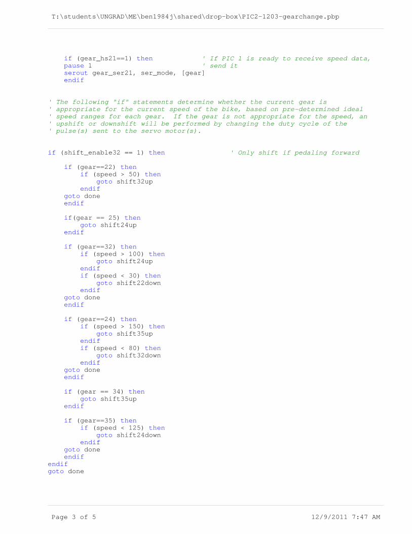
' The following "if" statements determine whether the current gear is' appropriate for the current speed of the bike, based on pre-determined ideal' speed ranges for each gear. If the gear is not appropriate for the speed, an' upshift or downshift will be performed by changing the duty cycle of the' pulse(s) sent to the servo motor(s).
if (shift_enable32 == 1) then ' Only shift if pedaling forward if (gear==22) then if (speed > 50) then goto shift32up endif goto done endif if(gear == 25) then goto shift24up endif
if (gear==32) then if (speed > 100) then goto shift24up endif if (speed < 30) then goto shift22down endif goto done endif
if (gear==24) then if (speed > 150) then goto shift35up endif if (speed < 80) then goto shift32down endif goto done endif
if (gear == 34) then goto shift35up endif
if (gear==35) then if (speed < 125) then goto shift24down endif goto done endifendifgoto done
Page 3 of 5 12/9/2011 7:47 AM
T:\students\UNGRAD\ME\ben1984j\shared\drop-box\PIC2-1203-gearchange.pbp
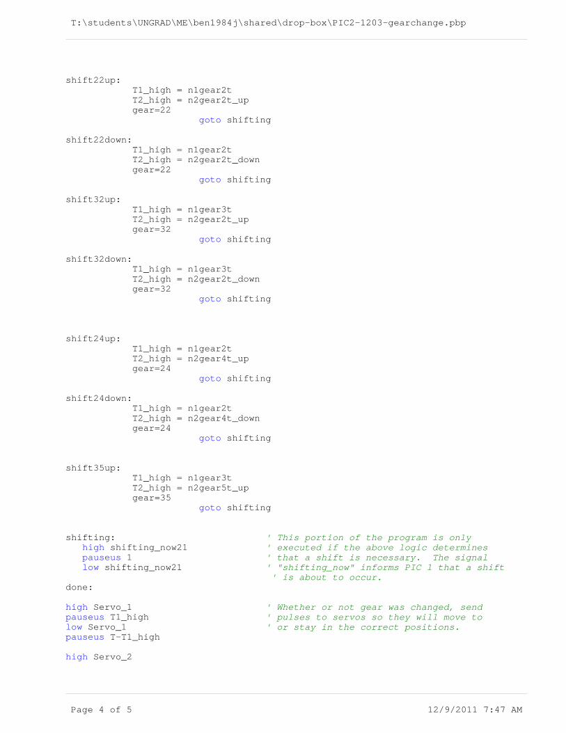
shift22up: T1_high = n1gear2t T2_high = n2gear2t_up gear=22 goto shifting shift22down: T1_high = n1gear2t T2_high = n2gear2t_down gear=22 goto shifting shift32up: T1_high = n1gear3t T2_high = n2gear2t_up gear=32 goto shifting shift32down: T1_high = n1gear3t T2_high = n2gear2t_down gear=32 goto shifting shift24up: T1_high = n1gear2t T2_high = n2gear4t_up gear=24 goto shifting shift24down: T1_high = n1gear2t T2_high = n2gear4t_down gear=24 goto shifting
shift35up: T1_high = n1gear3t T2_high = n2gear5t_up gear=35 goto shifting
shifting: ' This portion of the program is only high shifting_now21 ' executed if the above logic determines pauseus 1 ' that a shift is necessary. The signal low shifting_now21 ' "shifting_now" informs PIC 1 that a shift ' is about to occur.done:
high Servo_1 ' Whether or not gear was changed, sendpauseus T1_high ' pulses to servos so they will move tolow Servo_1 ' or stay in the correct positions.pauseus T-T1_high
high Servo_2
Page 4 of 5 12/9/2011 7:47 AM

T:\students\UNGRAD\ME\ben1984j\shared\drop-box\PIC2-1203-gearchange.pbp
pauseus T2_highlow Servo_2pauseus T-T2_high goto mainend
Page 5 of 5 12/9/2011 7:47 AM

T:\students\UNGRAD\ME\ben1984j\shared\drop-box\PIC3-1202 (2).pbp
'Program for PIC #3 - Shaft Encoder
define OSC 8OSCCON.4 = 1 : OSCCON.5 = 1 : OSCCON.6 = 1ANSEL=0
OPTION_REG = $FFINTCON=$90
on interrupt goto statechange ' When the shaft encoder outputs change state, ' the program will stop its normal operation ' and execute a service routine which compares ' past and present values of the shaft encoder ' outputs.
shaftenc_1 var PORTB.1 ' The two shaft encoder outputs are connectedshaftenc_0 var PORTB.0 ' to these pins.
oldval_1 var byte ' These two variables are used to store the past oldval_0 var byte ' state of the shaft encoder (prior to it changing).newval_1 var byte ' These two variables are used to store the newnewval_0 var byte ' state of the shaft encoder (after it changes).
shift_enable32 var PORTA.1 ' This line will be asserted high by the ' program if it is determined that pedal rotation ' is in the forward direction. Otherwise, the line ' will be low. PIC #2 will be connected to this ' line, and will not shift unless it is high.
time var word ' This variable is used in the main program loop ' to keep track of elapsed time, measured in 10 ' microsecond increments. At the end of each ' 10us increment, the program checks for ' interrupts, and if none have occurred "time" is ' incremented and the process repeats. Once the ' elapsed time reaches a preset value determinedmax_time con 1200 ' by "max_time" (this only happens if the shaft ' encoder doesn't change state during that time) ' the pedals can be assumed to be stationary, and ' the shift enable signal will be set low.
main: time = 0 while (time != max_time)' Waits up to max_time milliseconds for the ' shaft encoder outputs to change state.
disable ' Interrupts must not be serviced during these ' two assignment statements, in which the ' current values of the shaft encoder inputs are oldval_1 = shaftenc_1' stored as variables for later processing. If an oldval_0 = shaftenc_0' interrupt occurs while the first statement is ' being executed, the second shaft encoder input ' will not yet have been updated, and thus the ' pair of digits oldval_1 and oldval_0 will contain enable ' misleading position information. pause 1 ' After saving the values of the shaft encoder time = time + 1 ' outputs, the program waits for 1 ms to see if ' these outputs will change state. If they do, ' an interrupt will occur and the direction of ' rotation can be established. Otherwise, the ' process repeats. wend
Page 1 of 2 12/9/2011 7:11 AM

T:\students\UNGRAD\ME\ben1984j\shared\drop-box\PIC3-1202 (2).pbp
low shift_enable32 ' If the shaft encoder hasn't changed state by the ' end of this loop, the pedals can be considered to ' be stationary, so a shift should not be allowed ' to occur.goto main
disable
statechange: INTCON.1 = 0 time = 0 newval_1 = shaftenc_1 'Read new state of shaft encoder.newval_0 = shaftenc_0
if (newval_1 == 0) && (newval_0 == 0) then 'By comparing the new state of if (oldval_1 == 1) && (oldval_0 == 0) then'the shaft encoder to its old high shift_enable32 'state, the direction of pedal else 'rotation can be determined. If the low shift_enable32 'pedals are moving forward it is endif 'OK to shift.endifif (newval_1 == 0) && (newval_0 == 1) then if (oldval_1 == 0) && (oldval_0 == 0) then high shift_enable32 else low shift_enable32 endifendifif (newval_1 == 1) && (newval_0 == 1) then if (oldval_1 == 0) && (oldval_0 == 1) then high shift_enable32 else low shift_enable32 endifendifif (newval_1 == 1) && (newval_0 == 0) then if (oldval_1 == 1) && (oldval_0 == 1) then high shift_enable32 else low shift_enable32 endifendif
resume
enable
end
Page 2 of 2 12/9/2011 7:11 AM

T:\students\UNGRAD\ME\ben1984j\shared\drop-box\PIC4-1202 (2).pbp
'Program for PIC #4 - Speed Sensor
define OSC 8OSCCON.4 = 1 : OSCCON.5 = 1 : OSCCON.6 = 1ANSEL = 0
sensor var PORTB.0 ' The speed sensor is connected to ' this input.
speed var byte ' Based on how many pulses ' occurred during a certain time interval, ' the speed in mph can be computed. The ' variable "speed" contains this speed in ' mph, multiplied by 10 (this is done to ' get rid of the decimal place - explained ' in more detail elsewhere).speed_calc var word ' It is necessary to use a word, rather than ' a byte, for calculating the speed. Although ' the final value of the speed will be less than ' 255, it takes on larger values during the ' calculation process.speed_ser41 var PORTB.7 ' This pin is used to serially transmit ' the current speed data to PIC #1.speed_hs41 var PORTB.6 ' A handshake line is used to synchronize ' this communication.
speed_ser42 var PORTB.5 ' In a similar fashion, these lines are usedspeed_hs42 var PORTB.4 ' to send speed data to PIC #2.
ser_mode con 2 ' 2400 baud serial communication is used ' throughout.
counter var byte ' This variable keeps track of how many ' pulses from the speed sensor ' occurred during the time interval.
main: count sensor, 250, counter ' Counts the pulses from the speed sensor speed_calc = counter * 400 / 132 ' over a 0.25 second interval, and uses this speed = speed_calc.lowbyte ' quantity to calculate the speed in mph. if (speed_hs41 == 1) then ' Sends speed data to other pauseus 1 ' PIC's if they are ready. serout speed_ser41, ser_mode,[speed] endif if (speed_hs42 == 1) then pauseus 1 serout speed_ser42, ser_mode, [speed] endif goto main end
Page 1 of 1 12/9/2011 7:03 AM