Automatic Screw Feeder
37
Automatic Screw Feeder Neji Taro V HSV series HSV-10 HSV-12 HSV-14 HSV-17 HSV-20 HSV-23 HSV-26 HSV-30 Instruction Manual Read this manual before using this device. Current as of October 2021 21A No. ET-D001 HIOS Inc. 1-35-1 Oshiage, Sumida-ku Tokyo, Japan 131-0045 TEL: +81-3-6661-8821 FAX: +81-3-6661-8828
Transcript of Automatic Screw Feeder

Automatic Screw Feeder
Neji Taro V
HSV series HSV-10 HSV-12 HSV-14 HSV-17 HSV-20 HSV-23 HSV-26 HSV-30
Instruction ManualRead this manual before using this device.Current as of October 2021
21ANo. ET-D001
HIOS Inc. 1-35-1 Oshiage, Sumida-ku Tokyo, Japan 131-0045TEL: +81-3-6661-8821 FAX: +81-3-6661-8828

- 2 -
Contents1. OVERVIEW OF Neji Taro V Type ............................ 22. BEFORE USE ......................................................... 23. OPERATING PRECAUTIONS ................................. 34. NAMES OF MACHINE PARTS ............................... 65. ADJUSTMENTS AND CHECKS BEFORE USE ...... 76. PARTS ADJUSTMENTS AND REPLACEMENTS ... 15
1. OVERVIEW OF Neji Taro V TypeThank you very much for selecting our Automatic Screw Feeder “Neji Taro V Type”.This machine can line up screws (Type M1-M3) and supplies them one by one to increase the efficiency of screwing work.Different sizes of screws can be used by changing the rail, escaper, stopper assembly, escaper guide-right and the passing plate.It can be used wherever there is a power source for an AC adapter.
2. BEFORE USEPlease check for the following accessories before operating the machine. *CD-ROM 1 *AC adapter 1 unit *Hexagonal wrench 1 piece *Screwdriver 1 piece (For adjusting timer) *Ground wire 1 piece
7. EXTERNAL OUTPUT SIGNALS ............................... 278. MISCELLANEOUS .................................................... 28 Overload protective circuit9. TROUBLESHOOTING .............................................. 2910. SPECIFICATIONS ................................................... 3411. EXTERNAL DIAGRAM ............................................ 3612. THE FOLLOWING TABLE IS FOR CHINA RoHS2 ......... 37

- 3 -
3. OPERATING PRECAUTIONSThis manual contains safety alert symbols and signal words to help prevent injuries to the user or damage to property.
◎ Indications
This indicates there is a chance of death, serious injury or fire if the instructions are not followed.
This indicates there is a chance of personal injury or damage to property if the instruc-tions are not followed.
◎ Symbols indicating type of danger and preventative measures
Prohibited from doing. Never do this!
Do not disassemble, modify or repair.
Do not touch with wet hands.
This indicates to stop operations.
Unplug power supply from wall outlet.
General caution.
WARNING
CAUTION

- 4 -
WARNING
Do not disassemble the AC adapter as there is a risk of electric shock, fire or malfunction.
Do not damage, alter or change the power cord. Do not place heavy objects on the cord.Do not pull hard on the cord or twist the cord as it could be damaged, thereby causing a risk of fire or electric shock.
When using an outlet with AC100-240 V, don’t overload the electrical circuit. Do not modify or remodel this machine as this may cause a fire or electric shock.
Do not operate this machine near flammable liquids, gasses or materials as there could be a risk of fire or explosion.
Stop operating the machine and unplug the AC adapter from the wall outlet when you detect smoke, a pungent odor or any other unusual condition, as there may be a risk of fire or electric shock. Contact the dealer, from which you purchased the machine and have it examined and repaired.
Attachment of the earth wireWhen the earth wire is connected loosen the screw near the mark once.After inserting the U-shaped metal fitting of an attached cable, tighten the screw again.
In the case of a thunderstorm, stop operating the machine, turn off the power and unplug the AC adapter from the wall outlet. If there is lightning and thunder nearby, move away from the machine and do not touch it or the AC adapter.After the thunder stops, and when it is safe to do so, check the machine. If there is any abnormality, contact your dealer.
Do not handle the AC adapter with wet hands as it could cause an electric shock.
the bottom of the main body

- 5 -
CAUTION
Use only the AC adapter supplied with this machine otherwise it may result in a fire or electric shock.
Do not install this machine in an unstable location otherwise it may fall causing damage or injury.
Always operate the machine with the upper cover in place, otherwise it may result in injury.
Do not allow any foreign material to enter the machine while in operation.Do not put your fingers into the machine while in operation, otherwise an injury will result.Do not operate this machine in overly humid or dusty conditions. Keep the plug socket clean at all times otherwise it may cause a fire or electric shock.
When moving the machine, always disconnect the AC adapter from the wall outlet or it may result in damage to the cord, or cause a fire or electric shock.Turn off the machine and unplug the AC adapter from the wall outlet during closing hours or if the machine will be unused for any extended period of time.When performing maintenance, changing parts or when you sense an abnormality in the machine, turn the pow-er off and pull the AC adapter from the wall outlet.
Do not operate the machine with tension on the AC adapter cord. Keep the cord loose and untangled.
Do not bend, alter or damage the rail. Do not apply any oil. It is recommended that the user clean the rail periodi-cally.
Do not use any screw that is out of the specified range nor any screw that is oily or dirty.
When extracting screws, do not exert excessive force or shock to the screws.

- 6 -
4. NAMES OF MACHINE PARTS
Light-emitting sensor
Light-receiving sensor
Front cover
Rear cover
Right side cover
Rail
Escaper
Passing plateBrush
DC jackSignal line out
Timer knob
Vibration adjusting bolt (under the machine)
LED Screw sensor
Stopper assembly
Escaper bracket attaching bolt
Bit guide bracket
Rear cover fixing screws (2-left/2-right)
Stopper
Scooping chamberRail fixing bolt
Bit guide
Upper cover
Left side cover
Vibration adjusting plate fixing bolt
Power switch
Scooping block left and right
(moving up and down)
Escaper guide-right
Sensor bracket attaching bolt

- 7 -
5. ADJUSTMENTS AND CHECKS BEFORE USE5-1. Checking the model number of the main bodyCheck if the machine has the parts which match the nominal diameter of the screws to be loaded. Check the model number of the rail, escaper, stopper assembly, escaper guide-right and passing plate by referring to the following table. Each escaper, stopper assembly and escaper guide-right is stamped with a model number which corresponds with the type of screws that can be used.
Screw feeder model
Screw size
Rail model No.
Escaper model No.
Stopper assembly model No.
Escaper guide-right model No.
Passing plate
modelNo.HSV-10 M1.0 HSV-BI-10 HSV-SIE10 HSV-TPO20806-10 HSV-SIEM10
HS3-02052-1
HSV-12 M1.2 HSV-BI-12 HSV-SIE12 HSV-TPO20806-12 HSV-SIEM12
HSV-14 M1.4 HSV-BI-14 HSV-SIE14 HSV-TPO20806-14 HSV-SIEM14HSV-17 M1.7 HSV-BI-17 HSV-SIE17 HSV-TPO20806-17 HSV-SIEM17HSV-20 M2.0 HSV-BI-20 HSV-SIE20 HSV-TPO20806-20 HSV-SIEM20
HS3-02052-2
HSV-23 M2.3 HSV-BI-23 HSV-SIE23 HSV-TPO20806-23 HSV-SIEM23HSV-26 M2.6 HSV-BI-26 HSV-SIE26 HSV-TPO20806-26 HSV-SIEM26HSV-30 M3.0 HSV-BI-30 HSV-SIE30 HSV-TPO20806-30 HSV-SIEM30
Note: Screws, with a different nominal diameter, can be used by replacing the rail, escaper, stopper assembly, escaper guide-right and passing plate. The parts, for replacement, are available separately.
Before delivery, each section of the machine is checked and adjusted with panhead screws matching the nominal diameters of the ordered model. Most screws may be usable in the initial status of adjustment however, if the height or shape of the screw head is different or if the operation is regarded as abnormal, each section must be readjusted. If this is the case, make the following checks and adjustments:○ Check the screw load amount ○ Check and adjust the brush ○ Check and adjust the passing plate ○ Check and adjust the rail vibration ○ Check and adjust the holding plate ○ Check and adjust the front & rear sides of the rail ○ Check and adjust the timerIf the rail, escaper, stopper assembly, escaper guide-right and passing plate, of the machine, are replaced, screws with a different nominal diameter can be accepted. After these parts are replaced, fine adjusting is required. The respective adjusting procedures will be described elsewhere. Please read these procedures.
Escaper identification stamp
Stopper identification stamp
Escaper guide-right identification stamp
Rail identification seal
Passing plate identification seal

- 8 -
5-2. Amount of screws to be loadedAn excessive amount of screws, loaded into the chamber, will have an adverse effect on the screw alignment and transport. The figure, shown at right, indicates the maximum amount of screws to be loaded. Use this as a guide when loading the screws.
・ Turn the power switch ON and OFF so that the scooping block is at the lower limit position.
・ Load screws up to approximately 2-3 mm below the rail surface.・ At this time, check that screws are not loaded so as to cover the upper
portion of the inclined plate.・ Be sure to determine the screw load by observing the machine while it is
in operation.
5-3. Checking and adjusting the brushTurn OFF the power supply before checking and adjusting.
Load the screws into the scooping chamber, turn ON and OFF the power switch so that screws are aligned into the rail groove.
・ Turn ON and OFF the power switch so that the brush bristles are in a horizontal position as shown in the figure at right.
・ Check that the heads of the screws, in the rail groove, are in slight contact with the brush bristles.
・ When the brush height is too high or low, this will have an adverse effect on the screw alignment and transport.
・ If any adjustment is necessary, loosen the brush height adjusting bolt to adjust the brush height.
・ If the plastic portion, at the front of the brush, comes into contact with the passing plate, loosen the brush assembly mounting screw and make an adjustment either backward or forward.
・ Operate the machine to check that the brush operation is normal.
Screws, loaded into the chamber, must not be above the rail-groove surface.(The maximum screw load must be 2-3 mm below the rail-groove surface.)
Loaded screws Brush
Brush height adjusting bolt
Brush assembly attaching screw
The brush must not be in contact with the passing plate when it moves.
Passing plate
This inclined surface, on both the right and left inclined plates, should be visible.
Power switch
Turn On and Off the power switch to put the brush bristles in a hori-zontal position.
Move the brush by hand to check that the screws, in the rail groove, are in slight contact with the brush bristles and make adjustments if necessary.
Power switch

- 9 -
5-4. Checking and adjusting the passing plateTurn OFF the power switch before making any checks or adjustments.
・ Check that the passing plate is adjusted to a height that permits loaded screws to pass just within the clearance limit.
・ If the passing plate is too low, screws cannot pass. If the passing plate is too high, it will hamper a smooth transport of the
screws. ・ If adjustment is required, loosen the passing plate attaching bolt and
adjust the height.・ After making an adjustment, do an operational check.Note: Using the half-presses on both sides of the passing plate as guides,
slide the passing plate up or down.
5-5. Checking and adjusting the rail vibrationThis machine’s rail vibration can be adjusted.The screw transport speed differs depending on the screw type.Check the screw transport speed. If the rail vibration hinders a smooth transport of the screws, it can be adjusted.
・ Loosen the anti-vibration bolt at the rear of the machine. Next, turn the vibration adjusting bolt, located on the bottom of the machine, to adjust the vibration. When the bolt is turned clockwise, as viewed from the bottom of the machine, the vibration will increase. When the bolt is turned counterclockwise, the vibration decreases.
・ If the vibration is adjusted to a too large a value to increase the transport speed, the rail will hit against the escaper and screws may fall into the machine from the clearance, failing to unload screws normally. Adjust the vibration to a proper value that matches the loaded screws.
(Related item: Check and adjust the front and rear positions of the rail.)・ After making an adjustment, be sure to tighten the anti-vibration bolt.・ After making an adjustment, do an operational check.
Passing plate
Loaded screw
Passing plate attaching bolt
Half-press (provided on both sides of the passing plate)
The clearance should be just enough to permit the loaded screws to pass through the passing plate.
Weaker vibration
Vibration adjusting plate fixing bolt
Vibration adjusting bolt
Stronger vibration
The rail must not come in contact with the escaper. The clearance must not be too large.

- 10 -
5-6. Checking and adjusting the height of the bit guide bracket
Check the height of the bit guide bracket.・ Check that the clearance between the head of the loaded screw, in the
rail groove, and the bit guide bracket is 0-1 mm.・ If there is no clearance, a screw will be caught. If the clearance is too large, a screw pile or screw jump will occur.
・ If adjustment is required, loosen the bit guide bracket attaching bolt and make an adjustment either up or down.
・ If the bit guide bracket hits against the escaper, it will hinder the escaper motion.
・ After making an adjustment, check the machine operation.
5-7. Checking and adjusting the front/rear positon of the rail
If the rail comes into contact with the escaper, or the clearance between the rail and escaper is too large, when the machine is operated, loosen the rail fixing bolt and adjust the rail either backward or forward.After making an adjustment, be sure to tighten the rail fixing bolt.
・ If the rail hits against the escaper, the escaper will not function properly.・ If the clearance between the rail and the escaper is too large, screws
may fall into the machine.After making an adjustment, try making a vibration readjustment by referring to “Checking and Adjusting the Rail Vibration”.
The bit guide bracket must not come into contact with the escaper.
Rail fixing bolt
Adjust the rail either backward or forward.
Bit guide bracket
Loaded screw
Escaper
Bit guide bracket attaching bolt
Up/down adjustment
The clearance between the bit guide bracket and the head of the loaded screw should be 0-1 mm. The bottom of the bit guide bracket should be parallel to the rail-groove surface.

- 11 -
5-8. Checking and adjusting the bit guideCheck the bit guide position.
・ Adjust the bit guide to a position where the user can easily extract screws.
・ Try extracting screws a few times in order to adjust the position of the bit guide.
・ Adjust the bit guide by loosening the attaching bolts.
◎ Adjusting the guide plate ・When it is difficult to pick up screws with the bit, adjust the guide plate.・ Loosen the guide attaching screw and adjust the guide plate by
inserting the bit being use.・ After adjustment, check if pick up, with the bit being used, is smooth.
◎ Adjusting the groove between the bit guide and the guide plate.
・ The groove position between the bit guide and the guide plate should be such that it is easy for the user to extract screws.
・ Adjust the groove position by loosening the bit guide attaching bolt.・ After adjustment, check that the extraction of screws is smooth.
Check if it's easy to extract screws.
ScrewLeft guide plate
Right guide plate
Guide attaching screw
Bit guide
Screw
Bit guide
The bit guide attaching bolts
Adjustment
Adjustment
- 12 -
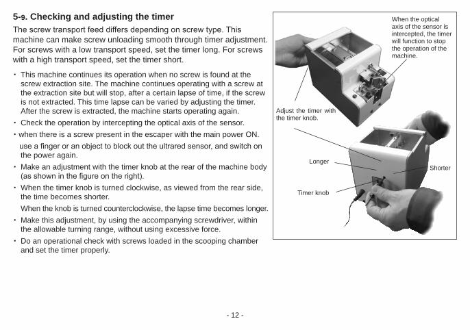
5-9. Checking and adjusting the timerThe screw transport feed differs depending on screw type. This machine can make screw unloading smooth through timer adjustment. For screws with a low transport speed, set the timer long. For screws with a high transport speed, set the timer short.
・ This machine continues its operation when no screw is found at the screw extraction site. The machine continues operating with a screw at the extraction site but will stop, after a certain lapse of time, if the screw is not extracted. This time lapse can be varied by adjusting the timer. After the screw is extracted, the machine starts operating again.
・ Check the operation by intercepting the optical axis of the sensor.・when there is a screw present in the escaper with the main power ON. use a finger or an object to block out the ultrared sensor, and switch on
the power again.・ Make an adjustment with the timer knob at the rear of the machine body
(as shown in the figure on the right).・ When the timer knob is turned clockwise, as viewed from the rear side,
the time becomes shorter. When the knob is turned counterclockwise, the lapse time becomes longer.
・ Make this adjustment, by using the accompanying screwdriver, within the allowable turning range, without using excessive force.
・ Do an operational check with screws loaded in the scooping chamber and set the timer properly.
Adjust the timer with the timer knob.
When the optical axis of the sensor is intercepted, the timer will function to stop the operation of the machine.
LongerShorter
Timer knob

- 13 -
5-10. Operation○ Loading the screws (cf. p8)
・ Open the upper cover. When the chamber plates are at their lowest position, load screws up to 2-3 mm below the rail groove surface.
・ Check that the screws are not loaded so as to cover the upper portion of the inclined plates. [CAUTION] Do not overload the chamber with screws otherwise it may cause a malfunction or damage the machine.
○ Turning ON the power・ Plug the attached AC adapter into the main body and power outlet. [CAUTION] Do not use any AC adapter other than the one included with this unit, as it may cause damage.
・ When the power switch is turned ON, the power switch lamp lights up. The scooping block starts to move up and down. The rail starts to vibrate and the escaper starts rotating.
・ Screws move along the rail towards the rotating escaper which selects one screw at a time.・ The escaper rotates and deposits the selected screw at the extraction site. ・ At this moment, the sensor detects a screw and the screw sensor LED lights up and then the operation stops.・ Until a screw is extracted, the machine stops operating.・ When a screw is extracted, the sensor detects this and the sensor LED light goes off and the machine resumes operation.
○ Pick uping Screws・ Screws can be extracted with an electric screwdriver using a magnetized bit.・ Use the bit guide to put the screwdriver down vertically into the screwhead’s slots, then pull the screwdriver, horizontally,
towards you as extracting the screw. To insert the screwdriver bit into the screwhead slots properly, it may be necessary to twist the driver slightly.
・ When inserting the screwdriver into the screwhead slots, do not use excessive force as it may alter the position of the escaper or cause damage to the machine.

- 14 -
[Reference] Refer to the following table for the recommended bit sizes.
5-11. MaintenanceA dirty rail groove may interfere with the screw transport speed.Clean the dirty rail with a soft, clean cloth dipped in alcohol. If cleaning is difficult, remove the rail from the machine and clean the rail groove. Before removing the rail from the machine, be sure to turn off the power supply and take the screws out of the chamber.If there is any dirt or a flaw in the rail groove that may cause an impediment in use, we recommend the user to replace the rail.
Loosen the rail fixing bolts and pull out the rail assembly from the rear side of the machine.
Clean the rail groove.
Rail fixing bolt
Put the screwdriver down vertically and insert the bit into the screwhead slots properly.
Pull the screwdriver towards you, horizontally and extract the screw.
Model No. Screw size recommended bit sizebit size screwhead slot No.
HSV-10 M1.0
∅1.5 No.0HSV-12 M1.2HSV-14 M1.4HSV-17 M1.7HSV-20 M2.0
∅2.0 or ∅2.3 No.0 or No.1HSV-23 M2.3HSV-26 M2.6 ∅3.0 No.1HSV-30 M3.0 ∅3.2 No.2

- 15 -
6. PARTS ADJUSTMENTS AND REPLACEMENTSThe brush and main motor are consumable parts. When using a different diameter of screw, the following items must be replaced: rail, stopper assembly, escaper and escaper guide-right.These parts may be ordered separately. The replacing and adjusting procedures are described below.When replacing any parts, a fine adjustment is required. Make these fine adjustments by reading the corresponding contents carefully. Before replacing any parts, be sure to remove all the screws from the chamber.
6-1. Replacing and Adjusting the BrushTurn OFF the power switch before starting replacement and adjustment.
If the brush is too worn to sweep screws off of the rail, replace it.A brush with harder bristles, than the standard brush, is available as an option. Consider its convenience when the situation requires it.
・ Turn ON and OFF the power switch in order to set the brush at the position shown in the figure on the right and detach the brush assembly.
・ The brush assembly can be disassembled as shown in the figure on the right.
・ For assembly, reverse the disassembling procedure.・ After completing the assembly, check that the front part of the brush
doesn’t come in contact with the passing plate. The ideal clearance is 0 mm.
・ For adjustment, refer to “Checking and Adjusting Before Operating the Machine”.
Part number of brush: HS3-02053 (standard brush)
Brush assembly attaching screw
Brushassembly
Passing plate
When the brush is operating, it should not come in contact with the passing plate.
BrushPassing plate
Spring washer
Hex socket head small boltM2.6×10
M2.6
M2.6Plain washer
Brush bracket#1Brush bracket#2
Brush

- 16 -
Remove the cover.
Disconnect the motor connector.
Remove the motor attaching screws.M2.6 X 8 2 pieces
Remove the motor attaching bracket towards the rear.
Pull the motor out towards the rear.
main motor unit
6-2. Replacing the Main MotorTurn OFF the power switch before starting to replace and adjust the main motor.
When the motor is damaged, replace it with a new one.・ First, remove the cover from the main body. Then, disconnect the connectors for the power switch and LED screw
sensor. This makes it easier to work within the body.・ Disconnect the motor junction connector.・ Remove the motor attaching screws on the bottom of the main body.・ Pull out the motor from the rear side of the main body. (If the motor is hard to pull out, insert an Allen wrench into the oblong
hole in the base of the body and push the motor attaching bracket backward.)
・ For reassembly, reverse the disassembling procedure. The combination of the operation timing for the left and right scooping
blocks is shown on the next page. Note: Do not use excessive force with the motor wiring in order to avoid
wire breakage.
Part number of main motor unit:HSVRB-09105-15

- 17 -
・ Assemble the motor section when the scooping blocks left and right are in the lowest position.
・ To get the left and right scooping blocks at almost the same height, clinch the drive gear of the motor shaft and the gears on the left and right, and tighten the motor bracket. (M2.6 x 8 - 2 pieces)
The left and right scooping blocks should be at the lowest posi-tion.
Right driving shaft bracket
Attaching screws at 4 positions
When it is hard to get a proper gear engagement, loosen the right driving shaft bracket then adjust the gears and tighten the screws.
When the right pin is vertical, the left pin should be inclined about 46°.
○ Operation Timing After Replacing the Main MotorTurn OFF the power switch before starting to replace and adjust the main motor.
・ To adjust the timing of the scooping block in respect to the brush movement, it is necessary to adjust the gear engagement.
・ When the motor has been removed from the main body, adjust the gear engagement of the motor, as shown in the figure on the right, then the operation timing can be adjusted.
・ When it is hard to engage the driving gear, of the motor, with the driven gear, loosen the drive shaft bracket (right) then this will facilitate the assembly. (Refer to the figure on the right.)
After assembling the motor, be sure to tighten the screws again.・ After installing the motor, switch the power ON to check the operation
timing. (Check that both right and left scooping blocks operate almost simultaneously.)
・ After doing an operation check, return the wiring arrangement to its original status. When installing the cover, be careful not to pinch any wires. Be careful that the wiring does not hinder the operation of moving parts. The wiring, on the inside, should not hinder adjustment made from the outside of the machine.
NOTE:To avoid breakage, do not use excessive force with the motor wiring.
- 18 -
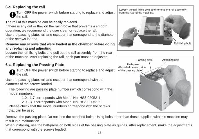
Loosen the rail fixing bolts and remove the rail assembly from the rear of the machine.
Rail fixing bolt
Attaching boltPassing plate Half-press
(Provided on each side of the passing plate.)
6-3. Replacing the railTurn OFF the power switch before starting to replace and adjust the rail.
The rail of this machine can be easily replaced.If there is any dirt or flaw on the rail groove that prevents a smooth operation, we recommend the user clean or replace the rail.Use the passing plate, rail and escaper that correspond to the diameter of the screws loaded.Remove any screws that were loaded in the chamber before doing any replacing and adjusting.Loosen the rail fixing bolts and pull out the rail assembly from the rear of the machine. After replacing the rail, each part must be adjusted.
6-4. Replacing the Passing PlateTurn OFF the power switch before starting to replace and adjust the rail.
Use the passing plate, rail and escaper that correspond with the diameter of the screws loaded.
The following are passing plate numbers which correspond with the model numbers:
1.0 - 1.7 corresponds with Model No. HS3-02052-12.0 - 3.0 corresponds with Model No. HS3-02052-2
Please check that the model numbers correspond with the screws that can be used.
Remove the passing plate. Do not lose the attached bolts. Using bolts other than those supplied with this machine may result in a malfunction.When installing, use the half-press on both sides of the passing plate as guides. After replacement, make the adjustments that correspond with the screws loaded.

- 19 -
The surface of the escaper should be lower than the surface of the rail.
Rail surfaceEscaper surfaceLine up the rail groove with an escaper notch.
No contact with the side of the rail, the stopper assembly and the escaper guide-right.
6-5. Replacing and adjusting the escaper, the stopper assembly and the escaper guide-right
Turn OFF the power switch before replacing.Turn ON the power switch when adjustments are necessary.
When using screws with a different diameter, replace the escaper, the stopper assembly, the escaper guide-right, the rail and the passing plate.
Before replacing the parts, remove all the screws from the chamber.First, remove the bit guide attaching plate and then replace and adjust the parts. After replacement, be sure to adjust and check the parts in the area of the escaper.
(Summary of the adjustment)Adjust moving parts to correspond with the rail.In terms of height, the level of the escaper surface should be lower than the level of the rail surface.Line up the rail groove with an escaper notch at the end of the reference point run. A reference point run is the detecting of the starting point of the escaper motor rotation. Also, make sure there is no contact with the side of the rail and the robot escaper guide.
Rail
Power switch
Light-emitting sensor
Stopper as-sembly
Bit guide attaching plate
LED screw sensor
Escaper Attaching bolt for bit guide
attaching plate
Light-receiving sensor
Escaper guide-right

- 20 -
① . Replace the escaper, stopper assembly and escaper guide-right.
Before replacement, remove any screws that were loaded in the chamber. First, remove the bit guide attaching plate, then replace and adjust the parts.
As looking at the front of the machine, start by removing the parts from the right side.
Start by removing, in this order: the escaper guide-right → escaper→spring holder (fixing the stopper assembly with screws)→ stopper assembly.
When you remove the spring holder, you can remove the flathead screw under the stopper. Do not lose the attaching screws and spacer.
For assembly of the replacement parts, reverse the disassembly procedure.After installing the spring holder, assemble the spring as shown in the figure at right.
The escaper notch needs to be adjusted to the rail groove position later. Assemble the escaper loosely as it will need adjusting later.
Escaper guide-right Escaper
Lastly, remove the
stopper assembly.
Spring holder
Spring holder
Stopper assembly
EscaperEscaper guide-right
Bit guide attach-ing plate
Spring holder
Stopper
Attaching bolt for bit guide
attaching plate
Stopper
Longer spring arm is on the upper
The spring arm should be under the washer
Shorter arm of the spring should be placed to the left side of the bent edge of the stopper.

- 21 -
Check the movement of the stopper before adjusting the parts in the area of the escaper.
・ The stopper should not be on the escaper.・ Rotate the stopper by hand, when released, it should return by means
of spring action.・ The stopper should be attached to the metal plate of the stopper
assembly.
② . Check and adjust the position of the escaper in relation to height and clearance.
Check that the clearances on the outside of the rail, between the stopper assembly and the escaper guide-right are almost even.
If they are in contact, the screws cannot be delivered.If there is too much clearance on either side, screws may fall into the machine.
When the clearances are not even, loosen the escaper bracket attaching bolt and adjust so that the clearances on the left and right of the rail are even. At this time, make the top surface of the escaper even to or slightly lower than the rail surface. If it’s too high, a screw won’t enter an escaper notch. If it’s too low, a screw will not enter a notch properly.
The stopper should not be on the escaper.
Escaper
Stopper
Rotate the stopper by hand, when released, it should return by means of spring action.The stopper should be attached to the metal plate of the stopper assembly.
The delete clearances, which are created on the outside of the rail between the stopper assembly, and escaper guide-right, should be even.
The escaper top surface should be the same height as the rail top surface or slightly lower.
Escaper bracket attaching bolt

- 22 -
③ . Adjust the escaper notch position.Turn the power switch ON while covering the sensor light axis. When the power is ON, the screw sensor LED lights up and the escaper motor moves around to the back, to the starting point. (Reference point run.) When the escaper motor is at the reference point, the escaper doesn’t move. When it is not at the starting point, the escaper motor moves oppositely around to return to the starting point and then stops. (Reference point run.)* Before adjustment, the starting point for the escaper motor and the position of the
escaper notch are not the same.* A reference point run is the detecting of the starting point of the escaper motor rotation.* Cover the sensor’s optical axis with a piece of paper.
When the power is on, the escaper motor has the ability to remain stationary. Make a reference point run-and-stop and when the escaper motor is stationary, then you can align the position of an escaper notchwith the rail groove.Fine adjustments can be made for the clearance between the end of the rail and the escaper by loosening the screws, on either side of the center of the escaper, and moving the escaper to an ideal position.Remember to tighten the screws again. After adjustment, turn the power witch OFF/ON in order to make a reference point run and check that an escaper notch and the rail groove align. After, remove the paper blocking the sensor’s optical axis and the escaper will start rotating.Check that all 4 notches of the escaper, each in rotation, stop at the rail groove.[Reference] It is possible to adjust, finely, the groove section as you adjust the position
of the escaper bracket. However, to do so, you must do as follows: *See ② “Check and Adjust “on page 20.
・There must not be any contact between the rail, the stopper and the escaper guide-right. Being in contact stops feeding the screws.
・The escaper top surface should be the same height as the rail top surface or slightly lower.
EscaperOval hole
Adjust an escaper notch position by loosening the screws and rotating the escaper.
Cover the sensor’s optical axis with paper.
Escaper bracket attaching bolt
Fine adjustment (Note: ② )
You can make fine adjustments for width clearance between the end of the rail and the escaper. Also, you can make fine adjustments for height clearance between the rail surface and the escaper surface.

- 23 -
④ . Explanation of the escaper movement before adjusting the sensor
When the power switch is turned ON, if there is no screw at the site where the screw is to be extracted, the escaper rotates with the screw sensor LED off.
The escaper rotates and accepts a screw from the rail.As the escaper rotates, it brings the screw to the screw extraction site.At this time, the sensor detects the screw, the LED lights up and the escaper stops.
When the screw is removed from the extraction site, the LED light goes off and the escaper rotates.
This is the correct sequence of operation. Usually, there is no need to adjust the sensor as it was done when assembled in the factory.
The following are irregular situations that require adjustment:- There is no screw at the extraction site but, the LED is on and the
escaper doesn’t rotate.- There’s a screw at the extraction site, but the LED is not lit and the
escaper rotates.
Accepting a screwLED screw sensor OFF
The screw is carried to the extraction site. LED screw sensor ON
Extracting the screw at the extraction site.LED screw sensor OFF
When the screw is at the extraction site, LED screw sensor ON.
When the screw is not at the extraction site, LED screw sensor OFF.
The rotation of the escaper, in the opposite direction, is a reference point run of the escaper motor.The rotation of the escaper, in the opposite di-rection, occurs when the power is turned on and the starting point of the escaper is not aligned with the reference point of the escaper motor. During regular operation, as in the figure above, the escaper rotates clockwise. (cf.)
[Reference]
LED screw sensor Power switchEscaper
Screw extraction site
Light-receiving sensor
Light-emitting sensor Stopper
Rail
Mark with circle is a screw
- 24 -
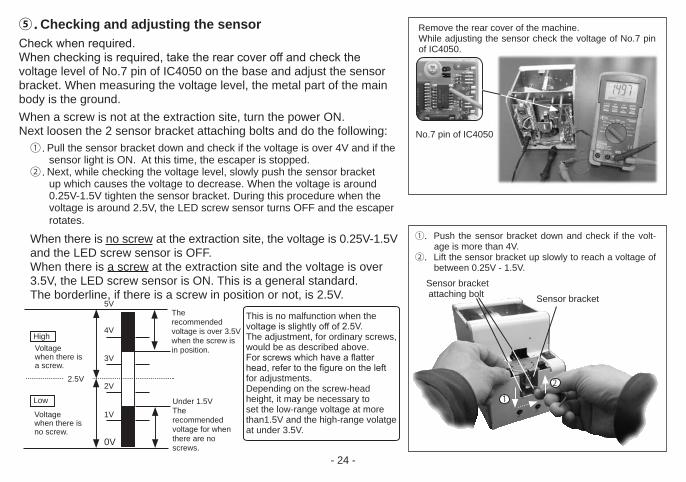
Remove the rear cover of the machine. While adjusting the sensor check the voltage of No.7 pin of IC4050.
No.7 pin of IC4050
1
2
①.Push the sensor bracket down and check if the volt-age is more than 4V.
②.Lift the sensor bracket up slowly to reach a voltage of between 0.25V - 1.5V.
This is no malfunction when the voltage is slightly off of 2.5V.The adjustment, for ordinary screws, would be as described above.For screws which have a flatter head, refer to the figure on the left for adjustments.Depending on the screw-head height, it may be necessary to set the low-range voltage at more than1.5V and the high-range volatge at under 3.5V.
5V
4V
3V
2V
1V
0V
2.5V
Voltagewhen there isa screw.
Under 1.5VThe recommended voltage for when there are no screws.
High
Low
The recommended voltage is over 3.5Vwhen the screw is in position.
Sensor bracket attaching bolt Sensor bracket
Voltagewhen there isno screw.
⑤ . Checking and adjusting the sensorCheck when required.When checking is required, take the rear cover off and check the voltage level of No.7 pin of IC4050 on the base and adjust the sensor bracket. When measuring the voltage level, the metal part of the main body is the ground. When a screw is not at the extraction site, turn the power ON. Next loosen the 2 sensor bracket attaching bolts and do the following:
① . Pull the sensor bracket down and check if the voltage is over 4V and if the sensor light is ON. At this time, the escaper is stopped.
② . Next, while checking the voltage level, slowly push the sensor bracket up which causes the voltage to decrease. When the voltage is around 0.25V-1.5V tighten the sensor bracket. During this procedure when the voltage is around 2.5V, the LED screw sensor turns OFF and the escaper rotates.
When there is no screw at the extraction site, the voltage is 0.25V-1.5V and the LED screw sensor is OFF. When there is a screw at the extraction site and the voltage is over 3.5V, the LED screw sensor is ON. This is a general standard. The borderline, if there is a screw in position or not, is 2.5V.

- 25 -
⑥.Operational checkAfter checking and adjusting each component, do an operational check with screws loaded.If any abnormality is found, make the said adjustments once again in addition to the rail vibration and front/rear position adjustments.After completing the operational check, return the wiring arrangement to its original status.When installing the cover, take care not to catch or pinch the wires. Watch that the wiring does not hinder the operation of this machine.
6-6. Replacing the stopperTurn OFF the power switch before replacing.
The stopper is a consumable part. When the stopper is worn-off or damaged in shape, replacement is necessary to ensure proper machine operations.(When stopper is being replaced, the escaper guide does not need to be removed from the machine.) Part number: E-Stopper HSV-TPO00512
・ Release longer end of the stopper spring from the spring holder, and unfasten the spring end nut. When unfastening the end nut, please be cautious that the washer underneath may spring out.
・ Disassemble the plain washer, stopper spring, and stopper in order.・ Install the new stopper, stopper spring, and washer in order. Fasten
the end nut while holding down the plain washer in place. During this process, please be careful not to allow the spring to become trapped by spring end nut and plain washer.
・ When the stopper spring assembly is completely fastened, fix the longer end of the spring onto the spring holder (as shown on right).
Please check if the stopper can move freely, and that the bottom edge of the stopper is completely aligned and parallel with escaper guide.
Spring holder Spring end nut
Stopper spring
Stopper
Longer arm of the spring should be fixed underneath the plain washer.
Shorter arm of the spring should be placed to the left side of the bent edge of the stopper.
Plain washer
Eacaper guide-left

- 26 -
Please make sure the tip of the stopper does not touch the escaper, as it may interfere with the escaper’s rotation.
If the end of the stopper is too close or too far from the escaper, please adjust the bent joint of the stopper where it makes contact with the spring holder, with a pair of long-nose pliers, so that the front of the stopper rests at the proper position. Spring holder
○ ×
×
Stopper touching the escaper
Joint in contact with the spring holder, where adjustments can be made. (to adjust position of the stopper)
Stopper being too far from the escaper

- 27 -
7. EXTERNAL OUTPUT SIGNALSThis machine can take out the screw extraction signal. Please use it for connection with general purpose counter etc. Since the signal line is stored inside, when using it please remove the back cover and pull out the signal line from the grommet.[Function]: Screw present: signal high (ON)Incoming current: shall be limited to less than 100mA **CAUTION: Additional resistor is required on external circuit for regulating current **[Capacity]: Max DC current: 100mA External supply voltage: 5-24V DC (Max: 27V DC)[caution]: Please keep the length of output signal wire less than 3m;* The purple wire functions as signal output high (Collector end), with the gray wire as common (Emitter end)
Purple line--->Signal line (OFF when no screw is present) (On when a screw is present)Gray line --->Common line
接続例Inside of the feeder
Outside of the feeder
Purple line
Gray line
Circuit diagram of the signal lines
Grommet
Signal line (CN10)

- 28 -
8. MISCELLANEOUS8-1. Overload protective circuitThis machine is equipped with an overload protective circuit.Normally, the driving motor rotates forward to feed screws to the escaper continuously.However, if there is an overload at the driving section, the driving motor rotates backward for a certain amount of time and then returns to normal rotation.When the cause for the overload is removed, during the reverse rotation, the driving motor returns to the normal rotation.If the cause of the overload is not removed, during the reverse rotation, the driving motor repeats the sequence of reverse rotation/normal rotation, reverse rotation/normal rotation to shut off the power to the driving motor. During this time, the escaper action is not stopped.When the power to the driving motor is shut off, turn OFF the power switch and remove the cause of the overload.For example, when too many screws are loaded into the scooping chamber, reduce the quantity of loaded screws to a proper level.If any screw is caught in the transport section, remove it.After removing the cause of the overload, turn ON the power switch to operate the machine. (Power reset)

- 29 -
9. TROUBLESHOOTINGFor safety, always unplug the AC adapter from the wall outlet before making any adjustments.
Trouble Cause Corrective measures
9-1The machine does not operate though the power switch is turned ON.
・Power is not supplied.
・The machine has not unloaded screws from the extraction site for a certain amount of time.
・Too many screws were loaded into the scooping chamber.
・A foreign object (for example: a screw) intruded into the main body.
・The AC adapter is faulty.
・Check the connection of the power supply of the AC power adapter.
・Take out the screw from the extraction site.
・Adjust the timer setting knob.
・ Reduce the quantity of screws in the scooping chamber to a proper load level.
・Remove the foreign object.
・ Consult your distributor.
9-2Screws do not flow.
・Screws with a larger diameter than the specified rail size were loaded or screws with a different diameter were mixed in together.
・ An insufficient quantity of screws are in the scooping chamber.
・Use screws with the specified nominal diameter.
・Remove the screws with the odd nomi-nal diameter.
・Add a proper quantity of screws into the scooping chamber.

- 30 -
Trouble Cause Corrective measures
9-2Screws do not flow. ・Screws in an abnormal position in the
passing plate cannot be swept away with the brush.
・The axis of the screw thread entered the passing plate.
・A screw has stopped in an abnormal position while moving on the rail.
・The rail does not vibrate. (For example, a screw is obstructing the
clearance.)
・Adjust the brush.Adjust the passing plate.If a proper amount of screws are loaded into the scooping chamber, the status may be improved.
・Remove the abnormal screw and check and adjust the passing plate.
・ Remove the screw in the abnormal
position. Take care not to damage the rail groove.
Move the bit guide bracket upward to remove the screw. After, adjust the position of the bit guide bracket in relation to height and direction.
・Remove the screw that is obstructing the clearance.
・ Check the vibration adjustment. If no screw is obstructing the clearance,
consult our service section.
9-3A screw has fallen into the rail groove.
・Screws with a smaller diameter than the specified rail size were loaded.
・Screws with a shorter total length than the rail groove width were loaded.
・Use screws with the specified nominal diameter and length.
・No corrective measure is available. Consult your distributor.

- 31 -
Trouble Cause Corrective measures
9-4The flow on the screw rail is improper. ・The clearance between the bit guide
bracket and the head of the loaded screw is narrow.
・ Screws with a spring washer having one increment smaller than the specified nominal rail size were loaded.
・The rail is oily or dirty.
・The rail does not vibrate. (A screw is caught in the clearance.)
・The motor is worn.
・Adjust the height of the bit guide bracket.Adjust the vibration.
If, after following the instructions written above, the machine still does not function properly, consult our service section.
・Clean the rail.
・Remove the screws caught in the clearance. If there is no screw that is caught, consult our service section.
・Adjust the vibration.
・Replace the motor. [Part No: HSVRB- 09105-15]
9-5Screws tend to pass through the passing plate in an abnormal position.
The axis of the screw thread tends to enter the passing plate.
・The passing plate is not adjusted properly.
・Too many screws are in the scooping chamber.
・Adjust the passing plate.
・Reduce the quantity of screws to a proper level.
9-6No screw comes to the extraction site. ・Screws are stopped while still on the rail.
・Screws cannot be transferred smoothly from the rail to the escaper.
・Adjust the height of the bit guide bracket.
・Adjust the distance between the end of the rail and the escaper as well as the height of the escaper in relation to the rail.

- 32 -
Trouble Cause Corrective measures
9-7The machine stops its operation suddenly. ・The overload protective circuit was
activated.
・Too many screws are in the scooping chamber.
・A screw is caught in the clearance.
・A screw, at the extraction site, could not be extracted for an amount of time.
・Turn the machine OFF and then ON again.
・Remove the cause of overload.
・Remove screws to a proper level.・When the machine stops, even if the
screws are at a proper level, consult our service section.
・Remove the screw that is caught.
・Remove the screw.
9-8The scooping operation does not stop though screws are at the extraction site.
・The timer knob is not properly adjusted. ・Readjust the timer knob.
9-9The escaper operation does not stop though screws are at the extraction site.
・The sensor does not detect a screw. ・Readjust the voltage of the sensor.
9-10A screw has fallen into the machine. ・Shake the screw down through the hole
at the bottom of the machine.

- 33 -
Trouble Cause Corrective measures
9-11The noise of the machine has increased. ・There is insufficient grease. ・Apply grease to the transport section.
○ Recommended grease: BR2 Plus , Dow Corning Asia Co. Ltd.
9-12The escaper does not rotate when no screws are present, although the indicator light is on.
・Undesired objects blocking front screw sensor.
・Adjustment of the front screw sensors is unsuitable.
・Make sure there are no debris or other objects present in the sensor brackets.
・If the escaper or stopper is damaged or worn-off, parts replacement is recommended.
・Adjustment on front screw sensors as shown on P.24.
9-13The escaper rotates in the wrong direction. ・When the escaper is operating, some
alien object is preventing the escaper from rotating smoothly.
・Escaper and the escaper guide do not fit together.
・Please check if the bit-guide and its mounting bracket are both positioned correctly so that sensors are not interfered or blocked, and that the screw can move freely.
・If the escaper or escaper guide is damaged or worn off, replacement is recommended.
9-14The escaper continues to rotate in the wrong direction.
・The origin sensor may be improperly adjusted.
・Please contact your dealer or our service section.

- 34 -
10. SPECIFICATIONS
PowerAC adapter
Power input AC:100V-240V 50/60Hz Power output DC:15V 1A
Dimensions 123(W) x 181(D) x 145(H) mmWeight Approx. 3 kg (including rail)Screw capacity Approx. 80ccFollowingaccessories
CD-ROM 1AC Adapter 1 unitHexagonal Wrench 1 pieceScrewdriver 1 piece Ground Wire 1 piece
Screw feeder model
Reference table of the specified screws Shape of screw head
Screw size
Screw shaft diameter
(∅)
Screw head diameter
(∅)
Screw head thickness
(mm)
Screw shaft length
(mm)
No.0 Pan head Pan head
Pan headBind
Counter sunk headSems Double
semsWasher
head
HSV-10 M1.0 0.9 - 0.95 1.8 - 4.5 0.35 - 1.0 1.6 - 10 ○ ー ー ー ー ー ー
HSV-12 M1.2 1.1 - 1.15 1.8 - 4.5 0.35 - 1.0 1.9 - 10 ○ ー ー ー ー ー ー
HSV-14 M1.4 1.3 - 1.4 2.0 - 4.5 0.35 - 1.0 2.2 - 10 ○ ー ー ー ー ー ー
HSV-17 M1.7 1.6 - 1.7 2.5- 4.5 0.35 - 1.0 2.7 - 10 ○ ー ー ー ー ー ー
HSV-20 M2.0 1.9 - 2.1 3.0 - 6.0 0.35 - 4.5 3.2 - 20 ー ○ ○ ○ ○ ○ ○
HSV-23 M2.3 2.2 - 2.4 3.3 - 6.0 0.35 - 4.5 3.7 - 20 ー ○ ○ ○ ○ ○ ○
HSV-26 M2.6 2.5 - 2.7 3.6 - 6.0 0.35 - 4.5 4.2 - 20 ー ○ ○ ○ ○ ○ ○
HSV-30 M3.0 2.9 - 3.2 4.0 - 6.0 0.35 - 4.5 4.8 - 20 ー ○ ○ ○ ○ ○ ○
* Compatible with washer diameter up to 9 mm, thickness 0.35 to 1.0mm.
Notes:- Please consult your distributor for thin head.- Check if the axis diameter of the loaded screw corresponds with the below rail groove width.- With therange of screw size and lengths below, there may be instances lf unique screw shape or stracture not com;atible with the screw feeder unit.- In the main body type, the main body model can be changed.- To change the nominal diameter of loaded screw, replace it with a part that is mentioned in the next page table.- The rail, escaper, stopper assembly, escaper guide-right and passing plate are separately available for replacement.- The design, performance and specifications are subject to change without prior notice for the sake of improvement.

- 35 -
SpecificationScrew feeder model
Screw size
Rail model No.
Escaper model No.
Stopper assembly model No.
Escaper guide-right model No.
Passing plate model
No.HSV-10 M1.0 HSV-BI-10 HSV-SIE10 HSV-TPO20806-10 HSV-SIEM10
HS3-02052-1HSV-12 M1.2 HSV-BI-12 HSV-SIE12 HSV-TPO20806-12 HSV-SIEM12HSV-14 M1.4 HSV-BI-14 HSV-SIE14 HSV-TPO20806-14 HSV-SIEM14HSV-17 M1.7 HSV-BI-17 HSV-SIE17 HSV-TPO20806-17 HSV-SIEM17HSV-20 M2.0 HSV-BI-20 HSV-SIE20 HSV-TPV20806-20 HSV-SIEM20
HS3-02052-2HSV-23 M2.3 HSV-BI-23 HSV-SIE23 HSV-TPO20806-23 HSV-SIEM23HSV-26 M2.6 HSV-BI-26 HSV-SIE26 HSV-TPO20806-26 HSV-SIEM26HSV-30 M3.0 HSV-BI-30 HSV-SIE30 HSV-TPO20806-30 HSV-SIEM30
○Replacement parts
・Rail ・Escaper ・Stopper assembly ・Escaper guide-right ・Passing plate
・Main motor unit ・Stopper ・Brush assembly ・Bit guide assembly HSV-07115 HSV-TPO000512 HS3-02053 HSV-06103
In the Exchange kit ordered, Rail assembly, Escaper, Stopper assembly, Escaper guide-right and Passing plate are included.

- 36 -
11. External Diagram
A (Distance to center of screw)
* Height to top of escaper
*
Unit:mm
S c r e w Size
Approximatemeasurement
of AΦ1.0 7.2Φ1.2 7.3Φ1.4 7.4Φ1.7 7.6Φ2.0 7.7Φ2.3 7.9Φ2.6 8.0Φ3.0 8.2
The dimensions in the manuals are for reference only do not use it for your jig.The specifications are subject to change without notice.

- 37 -
12. THE FOLLOWING TABLE IS FOR CHINA RoHS2.If you are asked by China Customs, please show this table to them.
有害物质名称及含量标识格式
产品中有害物质的名称及含量
部件名称有害物質
铅(pb) 汞(Hg) 镉(Cd)六价铬
(CR(VI))
多溴联苯
(PBB)
多溴二苯醚
(PBDE)
驱动齿轮,
轴心部件× ○ ○ ○ ○ ○
铆钉 × ○ ○ ○ ○ ○
六角铜柱 × ○ ○ ○ ○ ○
电路板元件 × ○ ○ ○ ○ ○
连接器 × ○ ○ ○ ○ ○
-
-
-
本表格依据 SJ/T 11364 的规定编制。
○: 表示该有害物质在该部件所有均质材料中的含量均在 GB/T 26572 规定的限量要求以下。
×: 表示该有害物质至少在该部件的某一均质材料中的含量超出 GB/T 26572 规定的限量要求。
In addition, the China RoHS marks also is required at the product and product box.At the product, you can find it at the bottom and it is marked on the product box.If you cannot find the mark, please ask your distributor.In case of emergency, please cut the mark below and stick at the bottom of product and on the product box.
China RoHS mark