Automatic Scenario Generation Using Procedural Modeling ...
135
University of Central Florida University of Central Florida STARS STARS Electronic Theses and Dissertations, 2004-2019 2012 Automatic Scenario Generation Using Procedural Modeling Automatic Scenario Generation Using Procedural Modeling Techniques Techniques Glenn Andrew Martin University of Central Florida Part of the Engineering Commons Find similar works at: https://stars.library.ucf.edu/etd University of Central Florida Libraries http://library.ucf.edu This Doctoral Dissertation (Open Access) is brought to you for free and open access by STARS. It has been accepted for inclusion in Electronic Theses and Dissertations, 2004-2019 by an authorized administrator of STARS. For more information, please contact [email protected]. STARS Citation STARS Citation Martin, Glenn Andrew, "Automatic Scenario Generation Using Procedural Modeling Techniques" (2012). Electronic Theses and Dissertations, 2004-2019. 2152. https://stars.library.ucf.edu/etd/2152
Transcript of Automatic Scenario Generation Using Procedural Modeling ...

University of Central Florida University of Central Florida
STARS STARS
Electronic Theses and Dissertations, 2004-2019
2012
Automatic Scenario Generation Using Procedural Modeling Automatic Scenario Generation Using Procedural Modeling
Techniques Techniques
Glenn Andrew Martin University of Central Florida
Part of the Engineering Commons
Find similar works at: https://stars.library.ucf.edu/etd
University of Central Florida Libraries http://library.ucf.edu
This Doctoral Dissertation (Open Access) is brought to you for free and open access by STARS. It has been accepted
for inclusion in Electronic Theses and Dissertations, 2004-2019 by an authorized administrator of STARS. For more
information, please contact [email protected].
STARS Citation STARS Citation Martin, Glenn Andrew, "Automatic Scenario Generation Using Procedural Modeling Techniques" (2012). Electronic Theses and Dissertations, 2004-2019. 2152. https://stars.library.ucf.edu/etd/2152

AUTOMATIC SCENARIO GENERATION USING PROCEDURAL MODELING
TECHNIQUES
by
GLENN ANDREW MARTIN
B.S. University of Central Florida, 1992
M.S. University of Central Florida, 1995
A dissertation submitted in partial fulfillments of the requirements
for the degree of Doctor of Philosophy in Modeling and Simulation
in the College of Engineering and Computer Science
at the University of Central Florida
Orlando, Florida
Spring Term
2012
Major Professor: Charles E. Hughes

ii
© 2012 Glenn A. Martin
iii
ABSTRACT
Training typically begins with a pre-existing scenario. The training exercise is
performed and then an after action review is sometimes held. This “training pipeline” is
repeated for each scenario that will be used that day. This approach is used routinely and
often effectively, yet it has a number of aspects that can result in poor training.
In particular, this process commonly has two associated events that are
undesirable. First, scenarios are re-used over and over, which can reduce their
effectiveness in training. Second, additional responsibility is placed on the individual
training facilitator in that the trainer must now track performance improvements between
scenarios. Taking both together can result in a multiplicative degradation in
effectiveness.
Within any simulation training exercise, a scenario definition is the starting point.
While these are, unfortunately, re-used and over-used, they can, in fact, be generated
from scratch each time. Typically, scenarios include the entire configuration for the
simulators such as entities used, time of day, weather effects, entity starting locations
and, where applicable, munitions effects. In addition, a background story (exercise
briefing) is given to the trainees. The leader often then develops a mission plan that is
shared with the trainee group. Given all of these issues, scientists began to explore more
purposeful, targeted training. Rather than an ad-hoc creation of a simulation experience,
there was an increased focus on the content of the experience and its effects on training.
Previous work in scenario generation, interactive storytelling and computational
approaches, while providing a good foundation, fall short on addressing the need for

iv
adaptive, automatic scenario generation. This dissertation addresses this need by
building up a conceptual model to represent scenarios, mapping that conceptual model to
a computational model, and then applying a newer procedural modeling technique,
known as Functional L-systems, to create scenarios given a training objective, scenario
complexity level desired, and sets of baseline and vignette scenario facets.
A software package, known as PYTHAGORAS, was built and is presented that
incorporates all these contributions into an actual tool for creating scenarios (both manual
and automatic approaches are included). This package is then evaluated by subject
matter experts in a scenario-based “Turing Test” of sorts where both system-generated
scenarios and human-generated scenarios are evaluated by independent reviewers. The
results are presented from various angles.
Finally, a review of how such a tool can affect the training pipeline is included.
In addition, a number of areas into which scenario generation can be expanded are
reviewed. These focus on additional elements of both the training environment (e.g.,
buildings, interiors, etc.) and the training process (e.g., scenario write-ups, etc.).

v
I dedicate this to my mother and father.

vi
ACKNOWLEDGMENTS
First, I would like to thank my advisor and chair, Dr. Charles E. Hughes for his
encouragement and insight as I performed this research. He always showed great interest
in my work and supported me in many ways.
I would also like to thank the rest of my committee, Drs. J. Michael Moshell,
Stephen Fiore and Ali Orooji. They have contributed to my career whether directly on
this work or in previous endeavors. Dr. Moshell suggested the Turing Test approach to
evaluating this work and I am grateful to him for the suggestion. Dr. Fiore gave
wonderful advice on the Turing Test analysis, and Dr. Orooji gave handy advice on the
grueling, dissertation process itself! UCF is quite large these days, but mostly still has
the flavor of that small university and the collaboration I had with my committee is a
clear indication of that fact.
Many people at the Institute for Simulation and Training helped during this
research, but I would like to especially thank my laboratory group (the Interactive
Realities Laboratory, or IRL). I cannot individually list everybody here with whom I
have worked, but they all have contributed to the lab. I do want to call special attention
to Jason Daly, Matt Fontaine and Robert Louden who contributed to some of our
foundational work in manual scenario generation. The IRL is truly a special collection of
people of varying disciplines and it has been a great pleasure to work with them.
I would also like to thank Dr. Denise Nicholson and Dr. Stephanie Lackey for
their funding support of this work. We have worked together a couple of times on
projects. It is always a good collaboration and I think our two laboratories work very

vii
well together; let’s keep it going! I also want to thank Dr. Sae Schatz who helped talk
through the training science side of this work and who definitely contributed to making
the work better.
I also want to recognize and thank the reviewers that helped perform the
evaluation of this work. I told them I would keep them anonymous (so that they would
be free to offer their opinions) so I cannot list them here by name, but I do appreciate
their efforts greatly.
Finally, I thank my family for their support over the years. None of them
necessarily understand my work, but they are always glad to hear of my
accomplishments. Originally, I had kept my pursuit of this degree a secret from them
(hoping to surprise them when I sent graduation announcements out). However, sadly
my efforts on this doctoral research saw, first, the passing of my father in March 2009
and then, shockingly, the passing of my mother in November 2009. My parents never
knew that I was pursuing this degree, but I hope they would be proud.
I found that dealing with the death of your parents makes you very reflective. I
look back on my father’s and mother’s lives and I see how they have influenced my life
and made me the person I am today. My father was a hard worker, and he would take
work home at night and often take me with him into the office on Saturdays. I still
remember trying to hit the “control” and “c” keys in unison on a keyboard for the first
time in my life (as an eight or nine year old); it was on a giant CAT scanner in Elliot
Hospital in Manchester, NH. My mother always had a free spirit, and she enjoyed seeing
new places and trying new things. I will forever remember the trips to Boston and how

viii
one time she agreed to take the train back to Nashua (again, I was probably eight or nine
years old) even though I’m sure we already had bus tickets. A fairly known quotation
(author unknown) says “A hundred years from now it will not matter how much I earned,
what my job title was, or what type of car I drove, but the world may be different because
I touched the life of a child.” This certainly applies to my parents. Thanks, Mom and
Dad.

ix
TABLE OF CONTENTS
LIST OF FIGURES ......................................................................................................... xiv
LIST OF TABLES ............................................................................................................ xv
LIST OF ACRONYMS/ABBREVIATIONS .................................................................. xvi
CHAPTER ONE: INTRODUCTION ................................................................................ 1
The Training Process ...................................................................................................... 1
Scenario Generation ........................................................................................................ 2
Scenario-based Training ................................................................................................. 3
Effective Scenario-based Training .................................................................................. 5
Embedded Triggers ..................................................................................................... 5
Clearly-defined Goals ................................................................................................. 6
Variety ......................................................................................................................... 6
Psychological Fidelity ................................................................................................. 7
Complexity .................................................................................................................. 7
Organization .................................................................................................................... 7
CHAPTER TWO: BACKGROUND ................................................................................. 9
Existing Scenario Specifications .................................................................................... 9
Existing Semi-automated Scenario Generation Systems .............................................. 10
Interactive Storytelling ................................................................................................. 13
Computational Approaches ........................................................................................... 17
Automated Scenario Generation ................................................................................... 19
CHAPTER THREE: CONCEPTUAL MODEL .............................................................. 20

x
What is a Scenario? ....................................................................................................... 21
Scenario Generation Process ........................................................................................ 22
Training Objectives ....................................................................................................... 23
Complexity .................................................................................................................... 24
Baselines ....................................................................................................................... 25
Augmentations .......................................................................................................... 26
Vignettes ....................................................................................................................... 27
Satisfying Requirements ............................................................................................... 28
Review of Concepts ...................................................................................................... 29
Conceptual to Computational ....................................................................................... 29
CHAPTER FOUR: COMPUTATIONAL MODEL ........................................................ 32
Mapping Conceptual to Computational ........................................................................ 32
Training Objectives ................................................................................................... 32
Complexity ................................................................................................................ 34
Baselines ................................................................................................................... 34
Augmentations .......................................................................................................... 37
Triggers ..................................................................................................................... 38
Adaptations ............................................................................................................... 39
Vignettes ................................................................................................................... 40
Requirements ............................................................................................................ 41
Manual Scenario Generation ........................................................................................ 42
CHAPTER FIVE: PROCEDURAL SCENARIO GENERATION ................................. 44

xi
Procedural Modeling Process ....................................................................................... 44
Procedural Modeling Methods ...................................................................................... 45
Fractals ...................................................................................................................... 46
L-systems .................................................................................................................. 46
Extended L-systems .................................................................................................. 47
Shape Grammars ....................................................................................................... 51
Functional L-systems ................................................................................................ 52
Functional L-systems and Scenario Generation ........................................................... 53
Grammar Representation .......................................................................................... 54
A Simple Example .................................................................................................... 55
A More Complex Example ....................................................................................... 56
Analysis ..................................................................................................................... 58
Implementation ............................................................................................................. 60
CHAPTER SIX: SCENARIO GENERATION FRAMEWORK .................................... 61
A Scenario Generation System ..................................................................................... 61
Plug-in Architecture .................................................................................................. 62
Core ........................................................................................................................... 63
Message System ........................................................................................................ 63
Review of Key Plug-ins ............................................................................................ 65
Authoring .................................................................................................................. 66
Plug-in for Automated Scenario Generation ............................................................. 66
COGS ............................................................................................................................ 67
xii
Does It Work? ............................................................................................................... 68
CHAPTER SEVEN: A TURING TEST FOR SCENARIOS .......................................... 69
The Turing Test ............................................................................................................ 69
A Scenario Turing Test ................................................................................................. 69
Expert Review ............................................................................................................... 71
Analysis ..................................................................................................................... 72
Summary ....................................................................................................................... 77
CHAPTER EIGHT: CONCLUSION AND DISCUSSION ............................................ 78
Contributions ................................................................................................................ 78
Review .......................................................................................................................... 80
Closing the Loop ........................................................................................................... 82
Additional Testing ........................................................................................................ 84
Other Scenario Elements .............................................................................................. 84
Terrain ....................................................................................................................... 85
Buildings ................................................................................................................... 85
Object Placement ...................................................................................................... 85
Object Generation ..................................................................................................... 86
Behaviors .................................................................................................................. 86
Textual Description ................................................................................................... 87
After Action Review Analysis .................................................................................. 87
Adaptive Training ......................................................................................................... 87
APPENDIX A: SCENARIO TURING TEST QUESTIONNAIRE ................................ 89

xiii
APPENDIX B: SCENARIO TURING TEST RAW DATA ......................................... 105
LIST OF REFERENCES ................................................................................................ 112
xiv
LIST OF FIGURES
Figure 1: Typical Training Sequence .................................................................................. 1
Figure 2: A Training Objective ......................................................................................... 24
Figure 3: Diagram of Concepts ........................................................................................ 31
Figure 4: An Example Training Objective........................................................................ 33
Figure 5: An Example Baseline ........................................................................................ 36
Figure 6: Two Example Augmentations ........................................................................... 38
Figure 7: An Example Trigger .......................................................................................... 39
Figure 8: Two Example Adaptations ................................................................................ 40
Figure 9: An Example Vignette ........................................................................................ 41
Figure 10: Scenario Example ........................................................................................... 42
Figure 11: An Example of an (a) L-system and (b) one string it produces ...................... 47
Figure 12: Water, Elevation and Population Density Maps Affect Road Networks ........ 49
Figure 13: Simple Example of Grammar Representation ................................................. 55
Figure 14: More Complex Example of Grammar Representation .................................... 57
Figure 15: COGS Modules within PYTHAGORAS ........................................................ 62
Figure 16: An Example of COGS ..................................................................................... 67
Figure 17: Training Sequence with Automatic Scenario Generation. .............................. 83

xv
LIST OF TABLES
Table 1. Table of Concepts in Conceptual Model. .......................................................... 30
Table 2. GPA Results of 2x2 Study. ................................................................................ 73
Table 3. Scenario Turing Test Results from 2x2 Study. .................................................. 76
xvi
LIST OF ACRONYMS/ABBREVIATIONS
AAR After Action Review
CAN Combined Arms Network
CAS Close Air Support
COGS CAN-oriented Objective-based Generator of Scenarios
DVTE Deployable Virtual Training Environment
EBAT Event Based Approach to Training
FAA Federal Aviation Administration
FEAST Framework for Enabling Adaptive Scenario Generation for
Training
FiST Fire Support Team
FL-systems Functional Lindenmayer Systems
GPA Grade Point Average
GUI Graphical User Interface
IDF Indirect Fire
IRL Interactive Realities Laboratory
ISAT Interactive Specification Acquisition Tools
ISS Instructional Support System
IST Institute for Simulation and Training
JSAF Joint Semi-Automated Forces
JTAC Joint Terminal Attack Controller
KSA Knowledge, Skill and Attitude
L-systems Lindenmayer Systems
MSDL Military Scenario Definition List
xvii
PYTHAGORAS Procedural Yielding Techniques and Heuristics for Automated
Generation of Objects within Related and Analogous Scenarios
RRLOE Rapidly Reconfigurable Event-Set Based Line-Oriented
Evaluations
STRIPS Stanford Research Institute Problem Solver
T&R Training and Readiness
UJTL Universal Joint Task List
XML eXtensible Markup Language
1
CHAPTER ONE:
INTRODUCTION
Ever since the first flight simulator was created by Edwin Link, researchers have
investigated using simulators for training. Since this advent of the field, engineers and
computer scientists have created increasingly advanced simulators with constantly
improving realism. Similarly, psychologists have developed theories for improving the
effectiveness of simulation-based training. However, in only a few cases have the two
camps come together to develop a realistic simulation for effective training.
The Training Process
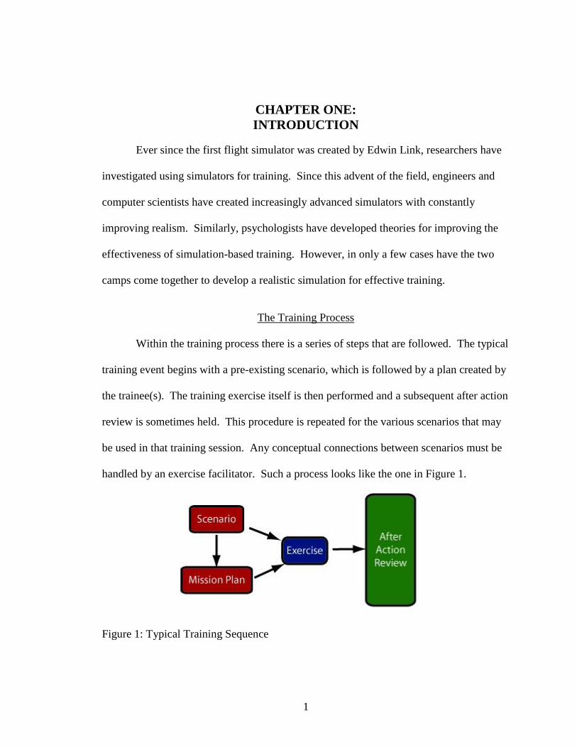
Within the training process there is a series of steps that are followed. The typical
training event begins with a pre-existing scenario, which is followed by a plan created by
the trainee(s). The training exercise itself is then performed and a subsequent after action
review is sometimes held. This procedure is repeated for the various scenarios that may
be used in that training session. Any conceptual connections between scenarios must be
handled by an exercise facilitator. Such a process looks like the one in Figure 1.
Figure 1: Typical Training Sequence
2
Unfortunately, this process can lead to two events that are undesirable. First, the
same scenarios are re-used over and over again, which can reduce their effectiveness in
training. Second, the individual training facilitator becomes responsible for tracking
performance improvements between scenarios. The combination of these two events can
lead to a multiplicative degradation in effectiveness.
There is a very old notion that you should not train specifically for the test [1]. In
addition, training in terms of new missions can also be an issue. The facilitator must
select a scenario for continued training, but has only a small set of scenarios from which
to do so. The same notions can exist for other domains when well-known scenarios wish
to be avoided or new types of scenarios are needed.
Due to these and other training issues, there has been increased attention on the
overall training process. Recently, a number of additional steps have been included to aid
in improved training effectiveness. One of these steps, scenario generation, is of
particular importance to the research presented in this thesis and so is reviewed here in a
bit more detail.
Scenario Generation
Running a simulation training exercise requires that we develop a scenario
definition as a starting point. However, prior to developing the scenario, a training needs
analysis should be performed that determines the set of Knowledge, Skill and Attitude
(referred to as KSAs) that are required as part of the training. Identifying the KSAs help
drive what the scenario must provide in order to satisfy the goals of the training and are
used to form the learning objectives (the underlying goals of the training). Furthermore,

3
completing this analysis helps drive the context of training; an analysis of the task is
performed, scenarios formed, an exercise run, and an after action review performed.
Typically, the scenario definition includes all the parameters for the simulators
themselves such as entities used, time of day, weather effects, and entity starting
locations as well as munitions effects. In addition, a story (or more formally, a mission
briefing) is given to the trainees based on similar information augmented with the
mission description (e.g. deliberate attack, search for weapons cache, etc.). The unit
leader then develops a mission plan that is shared with the trainee group as appropriate.
The notion of scenario generation can be generalized to other domains. For
example, a cognitive rehabilitation scenario could include the task to be practiced,
locations of items needed for the task, and possibly the layout of the training area itself.
Ultimately, scenario generation is required for all training exercises to provide the
context for the training to occur. This is a relatively expensive process that can benefit
from tools to aid in quickly creating such elements.
Scenario-based Training
While previous training tried to focus on the needs of the trainee as much as
possible, it was typically done in an ad-hoc fashion and, as noted, focused too much on
existing scenarios. In fact, some evidence of “negative training” has been reported
[2][3][4]. Negative training refers to the notion where a trainee learns a process
incorrectly or gains incorrect understanding. It is often not even recognized by the
trainee, which is why it is such a serious problem.

4
Given these issues, scientists began to explore more purposeful, targeted training.
Rather than an ad-hoc creation of a simulation experience, there was an increased focus
on the content of the experience and its effects on training. This resulted in two new
approaches: the event-based approach [5] and the scenario-based approach [3]. In reality,
both approaches are fairly similar. They focus on the role of events or the scenario in
learning. Specifically, the goal is to bring an order of events to the trainee to present a
“desired psychological state” [6].
So called “scenario based training” has gained wide acceptance as a training
concept. It provides the capability for trainees to explore a wide range of learning
including practice, cognitive skills and naturalistic decision making [7]. However, as
indicated above it is not always performed in practice (at least not all aspects).
This characteristic of a limited breadth of experiences is particularly troubling as
it has been found that development of advanced cognitive skills is dependent upon
extensive varied experience [8][9]. Specifically, the process of how an expert has built
up and integrated that knowledge was studied. It was found that experts use their large
quantity of experience and integrate them using the differences as a guide to larger
understanding.
Similarly, work in naturalistic decision making has theorized that experts make
decisions by leveraging a repository of experiences and use that collection to compare
situations [10]. This theory suggests that expertise depends upon exposure to a varied set
of experiences. Scenario-based training can provide that variability. In fact, a review of
scenario-based training found several ways where varied scenarios can enhance training.
5
Multiple, varied scenarios help trainees generalize their understanding and to be able to
adapt it to new situations [8]. In addition, varied scenarios allow trainees to try different
courses of action within a single scenario and also to practice an intended course of
action across different scenarios [9].
Effective Scenario-based Training
Scenario-based training, just by name, is not enough. What needs to go into a
scenario to support effective scenario-based training? Previous reviews of this topic
found five components to effective training scenarios [6]. Each is reviewed here.
Embedded Triggers
Training scenarios should provide the opportunities for trainees to practice their
skills, demonstrate their proficiency of those skills, and receive feedback on that
performance [3][11]. By designing scenarios to contain these “embedded triggers,” their
effectiveness is increased. For example, the Event Based Approach to Training (EBAT)
was created as a framework for providing events within an exercise that allow for
observation of specific behaviors of interest from the trainees [5].
In addition to EBAT, constraints such as empirical accuracy and empirical
precision provide another model for planning scenarios [12]. Empirical accuracy refers
to the degree to which all training objectives are built into a scenario; empirical precision
refers to whether only the desired training objectives (no extraneous objectives) are
included.

6
Clearly-defined Goals
When creating a scenario (whether by hand or in any assistive way), the process
must also have clear goals [11]. Not only should the goals be clear to the scenario
designer (or instructor) but to the trainees as well. If the latter is missing, then the
trainees may not respond in expected manners and may not practice the desired
knowledge and skills.
Furthermore, the goals should include performance measures. If the goals are
well defined, but not measured, then there is no indication of how well the trainee
completed the goals. If the goals are clearly defined, then having such performance
measures is an easier burden as well.
Variety
The need for scenario variety has been discussed earlier. However, it is still
essential to define what is meant by variability. Variety could be defined as the
generation of non-trivially diverse scenarios, meaning that they are not redundant for
training purposes [12]. Specifically, two scenarios are not redundant if they fulfill all the
requirements of the selected training objectives and differ by at least one significant
event. Fundamentally, what is needed is the ability to create scenarios that are somehow
qualitatively the same, yet still appear different to the trainee. How to do this or what it
means to be “qualitatively the same” are very interesting questions. In fact, scenario
variety is a ripe topic for further work.

7
Psychological Fidelity
Psychological fidelity refers to the “degree to which the trainee perceives the
simulation to be a believable surrogate for the trained task” [13]. To be successful, the
scenario has to be believable. This is particularly important as it has been found that
scenarios must be believable in order to be effective training scenarios [7]. Outlandish
scenarios may provide great entertainment value, but they are not effective in training.
Complexity
Similar to variety, trainees should also be tested on scenarios with varying
complexity in order to provide effective learning [14]. The term “complexity” is used
here in order to avoid the subjective term “difficulty.” What is difficult for one person
may not be for another. However, complexity is a more objective concept. Scenario
complexity can be a measure of task complexity and structure. Task complexity refers to
the number of discrete behaviors that form a task and the cues to be processed (referred to
as component complexity) and their integration for successful task completion (known as
coordinative complexity) [15]. Task structure refers to the degree of ambiguity within a
task [16].
Organization
This dissertation pursues the question of making training more efficient (both for
the trainees and the trainers) and whether an automated approach to scenario generation
can be created to fulfill the goal of targeting trainee needs. Specifically, the use of a
procedural modeling system known as Functional L-systems is used to create a variety of

8
scenarios that are different, yet qualitatively similar. Chapter 2 reviews the background
literature in this area including contributions from past scenario generation efforts and
interactive storytelling. A conceptual model of a scenario and how its various
components can be represented is then developed in Chapter 3.
Chapter 4 then maps the proposed conceptual model to a computational one. The
components of a scenario are developed into data structures and a manual approach to
scenario generation is reviewed to illustrate the process of scenario generation using these
structures. Automating this approach is the focus of Chapter 5. It includes a review of
procedural modeling and the approaches used to date, followed by a presentation of the
approach of Functional L-systems for scenario generation (including examples and
analysis of strengths and weaknesses of the approach).
Chapter 6 reviews the implementation of the scenario generation system
developed as well as the first scenario generation application built using it. The system is
analyzed using a form of the Turing Test, presented in Chapter 7, along with results.
Finally, Chapter 8 concludes and provides some discussion of improvements and
additions to the current system that are possible to improve the range of scenarios.

9
CHAPTER TWO:
BACKGROUND
In this chapter work related to scenario generation systems is reviewed. Most are
limited approaches that attempt to guide the user. However, some do provide important
improvements to scenario generation based on modern day design concepts.
Existing Scenario Specifications
In order to generate scenarios, there must be a way to represent them. Two pieces
of work from the U.S. Department of Defense are relevant here. The Universal Joint
Task List (UJTL) is a list of all possible tasks that may be part of an exercise within the
U.S. military. It provides a common language for commanders, support agencies,
planners and trainers and allows them to communicate mission requirements [17]. For
the purposes of scenario generation, it provides an exhaustive list of all possible tasks that
may or may not be executed as part of a military training scenario.
The Military Scenario Definition List (MSDL) attempts to provide a standard
language for representing military scenarios [18]. Its focus is on representing the
scenario in an application-independent manner and utilizes eXtensible Markup Language
(XML) in order to do so. The use of XML avoids scenario descriptions from being tied
to one particular application or platform, and also allows these descriptions to easily
contain all relevant data across the various components (planning, simulations
themselves, and scenario development applications).

10
The major limitation of both UJTL and MSDL is that they are very much tied to
military operations. Each works very well representing its respective aspects of military
scenarios; however, they are not easily extensible to other domains.
Existing Semi-automated Scenario Generation Systems
A number of projects in semi-automated scenario generation have been pursued in
recent years. In this section the most relevant of these are reviewed. In addition, lessons
to be learned from each are discussed.
An event-based approach to scenario generation is the Rapidly Reconfigurable
Event-Set Based Line-Oriented Evaluations (RRLOE) Generator [19][20][21]. RRLOE,
used in Federal Aviation Administration (FAA) simulators, builds scenarios from small
sub-scenarios that have been pre-approved by the FAA. The notion is that a larger
scenario made up of pre-approved, valid sub-scenarios will also be valid. RRLOE uses a
set of 128 heuristics to determine the adequacy of each scenario being constructed. The
heuristics are continuously evaluated while sub-scenarios are added; the process stops
when an acceptable scenario is reached. RRLOE is still used by the FAA for pilot
qualification testing and training.
Another tool, the Interactive Specification Acquisition Tools (ISAT), also uses
heuristics to build a scenario using smaller scenario pieces [22]. However, each scenario
piece is pre-built with a very specific sub-goal. As the scenario pieces are assembled into
the scenario, ISAT performs analysis to determine any error states that may exist within
the heuristic model. For example, ISAT can identify states that are never executed in a
scenario as well as those with conflicting “next” states. In addition, ISAT also has a
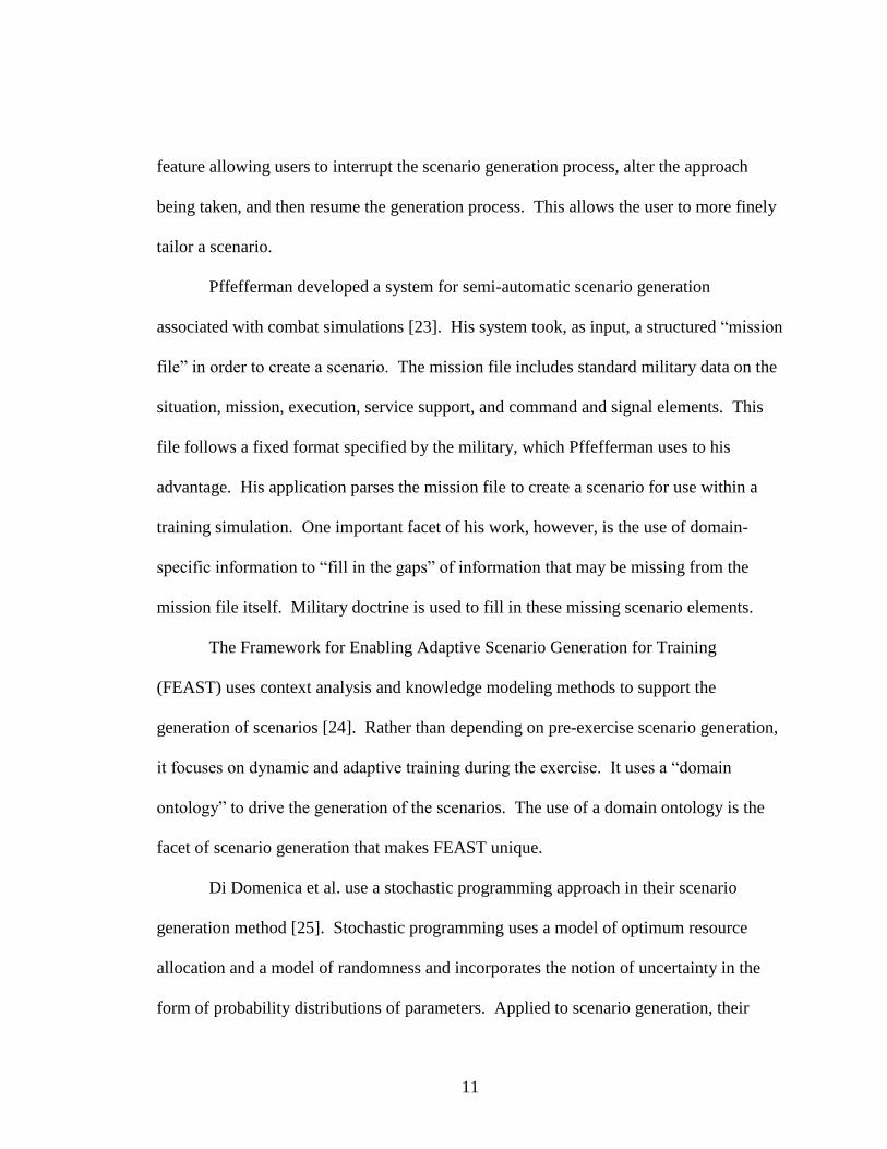
11
feature allowing users to interrupt the scenario generation process, alter the approach
being taken, and then resume the generation process. This allows the user to more finely
tailor a scenario.
Pffefferman developed a system for semi-automatic scenario generation
associated with combat simulations [23]. His system took, as input, a structured “mission
file” in order to create a scenario. The mission file includes standard military data on the
situation, mission, execution, service support, and command and signal elements. This
file follows a fixed format specified by the military, which Pffefferman uses to his
advantage. His application parses the mission file to create a scenario for use within a
training simulation. One important facet of his work, however, is the use of domain-
specific information to “fill in the gaps” of information that may be missing from the
mission file itself. Military doctrine is used to fill in these missing scenario elements.
The Framework for Enabling Adaptive Scenario Generation for Training
(FEAST) uses context analysis and knowledge modeling methods to support the
generation of scenarios [24]. Rather than depending on pre-exercise scenario generation,
it focuses on dynamic and adaptive training during the exercise. It uses a “domain
ontology” to drive the generation of the scenarios. The use of a domain ontology is the
facet of scenario generation that makes FEAST unique.
Di Domenica et al. use a stochastic programming approach in their scenario
generation method [25]. Stochastic programming uses a model of optimum resource
allocation and a model of randomness and incorporates the notion of uncertainty in the
form of probability distributions of parameters. Applied to scenario generation, their

12
method generates a tree structure of scenarios that best approximates a given distribution
of the random parameters. The parameters (and their behaviors) are chosen based on a
model of the scenario and are calibrated (often subjectively). These parameters are used
to generate paths, which are sampled to create the scenario tree with the desired
properties. The domain for this work was largely in economic systems; however, the
basic concept can still apply to other domains.
Reynolds defines a framework for scenario generation [26]. However, the
domain in which the work is based is risk management. She comments “the quality of
the resulting analysis, however, depends on the ability to generate relevant scenarios, a
task that grows increasingly complex with the proliferation of risk factors, models and
sampling techniques.” In other words, the number of potential variables can affect the
generation of the scenario itself. However, Reynolds also uses five questions for
providing an outline of the scenario set to be generated:
1. What is the purpose of the scenario set?
2. What risk factors must the scenario set include?
3. Do the risk factors need to be grouped or altered? If so, how
should it be done?
4. What marginal distribution or process is most appropriate for each
risk factor?
5. What are the technical considerations, such as run-time or
memory?
13
Reynolds then creates a framework built around a scenario set definition, scenario
generator, and a set of “blocks” (a group of risk factors) and models.
Many valuable lessons may be learned from these previous efforts. RRLOE and
ISAT show the advantages of using smaller, pre-made sub-components (which are pre-
certified, thereby helping with acceptance of the overall scenario. Pfefferman’s approach
shows that the data and rules of a specific domain can be used to support automated
generation by allowing it to fill in missing information. FEAST takes that notion one
step further using a full domain ontology to support scenario generation. Di Domenica
and Reynolds each show alternative approaches to scenario generation.
Even with these significant contributions, many challenges remain. For example,
none of these systems support more than one domain. Having a flexible system would
help avoid a “stovepipe” approach where a system works with only one set of training
applications. In addition, most of the systems reviewed do not incorporate the training
needs of the trainee; they take a “one size fits all” approach to scenario generation, which
does not lead to the most efficient use of training time (RRLOE is the exception).
Finally, the systems here take different computational approaches to scenario generation.
The heuristics-based approaches may or may not produce the best scenario whereas
others that search for a satisfactory scenario may be computationally inefficient.
Interactive Storytelling
Interactive storytelling is a relatively new field. It concerns a form of
entertainment where players take on the role within a storyline (particularly the
protagonist role). One important component of interactive storytelling is a strong

14
connection between a player’s actions and the story [27]. A number of interesting
systems have been created and some of the most relevant and most known are reviewed
here.
Façade is one of the most well-known interactive storytelling systems [28]. It is
based upon a story where you visit two friends who are married but quickly become
involved in a dispute leading towards the dissolution of their marriage. The player is
given situations attempting to force support to one side of the argument or the other.
Façade itself is a framework to create structured hierarchies of behaviors [28]. While the
behaviors are integrated together within Façade, a human author must take the time to
create each individual behavior. For the typical 20-minute Façade game, approximately
two man-years were spent creating it. Façade tries to blend an approach between
structured narrative and typical simulation. Much like some of the training-based work
already reviewed, Façade’s goal is to provide a well-formed experience where all parts of
the experience are necessary and the experience is well-paced, yet provides a sense of
immersion and freedom to act [28].
Mimesis is another well-known system [29]. However, rather than being a system
on its own as Façade is, it uses the Unreal Tournament as its base. UnrealScript is
written to represent conditions and actions for the story to take. However, Mimesis
distinguishes between preconditions and persistent preconditions. The latter are
conditions that must be true throughout the execution of the respective action. For
example, for a character to walk through a doorway, it must remain open for that entire

15
action [29]. A software “mediator” manages inputs from a user and uses intervention of
accommodation to prevent the story from breaking down.
Haunt 2 also uses the Unreal Tournament game engine and couples it with the
Soar artificial intelligence (AI) engine [30]. The story is written by a human author and
is fed into the software “director” software. It uses a partial-order plan, much like the
Mimesis system. The story is split into atomic events, which the system calls plot points.
These represent some story-based change to the world and are partially ordered to
assemble the scene. Each plot point can have a set of preconditions and a set of post
conditions. The preconditions represent what must be true in the story in order for the
plot point to be considered; the post conditions represent the actions to perform once the
preconditions are met.
Haunt 2 also provides a function to leave some content undefined. As opposed to
Façade or Mimesis (which keeps content of plot points fixed), the author can leave plot
content to be assigned by the “director.” The director will recognize missing plot content
and create it as appropriate.
IN-TALE is a system that focuses on the use of an experience manager, which is
an agent that alters the virtual world to provide an experience to the participant that
conforms to a set of properties [31]. It generates content that adapts to the user’s actions
within the world. Similar to other systems reviewed here, IN-TALE uses partially-
ordered plans. However, it uses a STRIPS-like language that includes parameters,
preconditions and effects. STRIPS (Stanford Research Institute Problem Solver) is an

16
automated planner developed in 1971 focused on tuples of current states, goal states,
preconditions and post conditions [32].
Scribe is an authoring tool being used within a project investigating interactive
storytelling for training [33]. The focus on the project is to combine interactive
storytelling with intelligent tutoring within a game environment. Scribe’s goals include
generality, improved debugging capability, usability, environment representation, pace
and timing, and story scope. In many ways, Scribe is similar to IN-TALE. The latter
focuses on the behaviors of agents and how the behaviors affect the story; the former
focuses on story representation and how actions influence the storyline for a trainee [33].
However, Scribe still uses plot points based upon a set of preconditions, a set of events
and a set of actions. Such an approach works well for generality, though, which is an
important advantage of these approaches.
Ponder et al. developed a virtual reality system that used interactive story for
decision training [34]. Their system is built around decisions as the basic building block
of a scenario. A decision is the “expression of the choice made to perform an action”
where an action is defined as a finite state machine with idle, activating, active and
terminating states [34]. Decisions can be grouped into decision sets where all decisions
must be taken in order to transition. This provides the ability to support compound
conditions before moving to the next scenario step.
Interactive storytelling provides many alternative approaches to developing
stories. In turn, stories have many similarities with scenarios. The Mimesis approach is
particularly illuminating in its distinction between preconditions and persistent

17
preconditions. Similarly, Haunt 2 and IN-TALE are interesting in their approach to leave
some of the content intentionally undefined until “run-time.” In many ways, they blur
story generation and story adaptation. Scribe and Ponder et al. use general approaches
that adapt to many different stories in a very easy fashion. Each of these examples
provides many compelling attributes to scenario generation.
Computational Approaches
In this section various computational approaches of current scenario generation
systems are reviewed. The basic approaches to scenario generation have been seed-
based, heuristic-based and enumeration-based in nature.
The seed-based approaches use a starting scenario as a basis and then perturb it in
order to create a new scenario [12]. The starting scenarios are typically created by a
human (normally a subject matter expert) so this approach is a semi-automatic one.
Since the starting scenarios are created by an expert, the basis for all the scenarios is of
relative high quality. However, the perturbations available can often reduce the
variability of the new scenarios. In addition, there is still the relative high cost of creating
the original seed scenarios; depending on the range of seed scenarios necessary, this can
be prohibitive.
Heuristic-based approaches use a set of rules (heuristics) to create scenarios that
satisfy some set of constraints. The components of the scenario are randomly selected
and then compared to the heuristics. If the constraints are satisfied, then the component
is kept within the new scenario. This process is repeated as components are added to the
scenario. This approach can also be quite effective in producing scenarios with

18
variability; unfortunately, it is also relatively computational inefficient. However, the
heuristic-based approach taken by RRLOE uses off-line computation (i.e., before the
training session itself) to reduce the time needed with trainees present.
Enumeration-based approaches are similar to their heuristic-based cousins.
Rather than using heuristics to select a component to add to a scenario, enumeration-
based approaches create all possible scenarios given starting conditions and then use
heuristics to evaluate each potential scenario. Such a technique can work where run-time
is not restricted and where the domain is not complex enough to rapidly expand the size
of the enumeration space.
All of these computational approaches have advantages and disadvantages. They
vary in set-up time, variability supported and computation time. However, there are other
computational models still available for use. One, procedural modeling, has been seeing
increased use in recent years as computer hardware has advanced.
Procedural modeling includes various techniques. One technique, Lindenmayer
Systems (or simply L-systems), are a recursive, rule-based system that operates in a
parallel fashion. Functional L-systems are an enhancement to L-systems that replace
symbols in the rules with functions, providing a greater computational capability. This
enhanced expressive power could provide a satisfactory approach to creating scenarios.
Chapter 5 will describe these techniques in greater detail.
Before a semi-automatic scenario generation system can be built, however, the
notion of a scenario must first be defined. These elements include both structures for
representing components of the scenario and also how each addresses a training

19
requirement as well as support for different trainees. The next chapter discusses a
conceptual model of a scenario.
Automated Scenario Generation
Given the lessons that can be taken from the works reviewed in this chapter, the
rest of this dissertation heads towards the goal of automated scenario generation. In order
to achieve this, a conceptual model of a scenario was created, mapped to a computational
model, implemented using Functional L-systems and then its results analyzed. The
remainder of this dissertation addresses these major contributions.

20
CHAPTER THREE:
CONCEPTUAL MODEL
Before any kind of automated scenario generation system can be approached, a
model for representing a training scenario must be created. The model should include not
only the parameters of a scenario, but also the sub-components of a scenario, a definition
of scenario complexity and a framework for linking the sub-components to learning
objectives and each other. Concrete definitions of each of these elements will enable
software to generate appropriate scenarios for specific trainees. However, a distinction
here is made between scenario generation (i.e., pre-exercise) and scenario adaptation (i.e.,
during exercise); the focus here is on the former.
This chapter describes the conceptual model of a scenario and its components. It
is based upon the notion of selecting “training objectives” that are used to choose a
“baseline scenario” and modifications, called “vignettes,” that add increased complexity
to the scenario. The training objectives are based upon the training audience (e.g. a
system for cognitive rehabilitation will have very different training objectives from a
system for military training). Baselines represent the overall environmental setting; they
include a virtual world to use as well as time-of-day and weather effects. Vignettes are
added to the baseline and provide for a greater overall complexity of the scenario. Given
the background of a trainee, a system should be able to assemble vignettes with a baseline
that results in a scenario that supports the specific training objectives, reaches appropriate
levels of complexity for that trainee, and provide adaptive training opportunity for the
trainee(s) to further their understanding and performance.
21
In addition to scenario generation based on trainee background, training science
suggests that scenarios for effective training should support varied pedagogical
approaches [35]. For example, a “compare and contrast” scenario where a particular
event is specified in two different ways or a “disequilibrium scenario” where the worst-
case scenario is given can enhance the trainee’s understanding.
What is a Scenario?
Before getting into the details of the conceptual model, a common understanding
of the term “scenario” is required. Specifically, a distinction between a simulation and a
scenario is made. A simulation refers to the use of a virtual environment to support
practice of a task (so called “simulation-based training”). In contrast, a scenario supports
scenario-based training where scenarios are used to create the purposeful instantiation of
simulator events to produce desired psychological states [36].
Given scenarios, however, there is a distinction to be made between a “scenario”
and a “situation.” Situations refer to instant snapshots, which occur at any given time
within an exercise; whereas scenarios can be thought of a series of situations over time
[37]. Therefore, one can think of a training scenario as a series of events that create
specific situations.
Finally, a training scenario uses a series of specific situations in order to facilitate
learning. In addition to simply describing the environmental context, training scenarios
should include pedagogical accompaniments such as training objectives and performance
measures. The former was already alluded to earlier whereas the latter is used for

22
tracking performance in order to better facilitate future scenario generation for that
trainee.
Scenario Generation Process
The basic process behind automated scenario generation can be conceptualized by
an Input-Process-Output model [38]. Inputs may include specific training objectives and
information about the trainees. Once these inputs are specified, the software will process
them and assemble a scenario. Finally, the software will then output a scenario definition
file.
Specifically, the inputs include preselected training objectives, an optional
recommended pedagogical approach and information about the trainees. The trainee data
can include the number of trainees, the roles in which they will participate in the
simulation as well as their levels of expertise. Once inputs are provided, the generation
system constructs a valid scenario that emphasizes the given training objectives that are
tailored to the specific trainees’ needs. A scenario actually has a number of specific
building blocks (briefly discussed above). All together these blocks are referred to as
facets of the scenario, each with a specific role to fulfill in formulating the scenario. The
output scenario definition is automatically assembled from pre-existing scenario
baselines and “vignettes” that represent an element of a scenario. The scenario is then
output and used within the various simulations for initialization of the exercise.

23
Training Objectives
The military formally defines training objectives in its Training & Readiness
(T&R) manuals. Each objective in the T&R includes a list of “conditions” that describes
the context under which the action can be performed. In the conceptual model for
scenarios, this basic approach is followed. Note, however, that training objectives can be
created for any particular domain desirable; it just happens that the approach used in the
T&R manuals generalizes well so it was included in the model posed here. However,
regardless of the domain being trained, it is important to enumerate the training
objectives for that domain. For more civilian domains (such as cognitive rehabilitation),
this enumeration would likely have to be completed with the aid of appropriate subject
matter experts.
Regardless of the domain in question, the training objectives for it will likely
include some context under which the actions within the objective can be performed. In
the conceptual model, these conditions become requirements for elements that must be
present in the scenario. For example, to train an artillery gunner to fire upon an enemy
convoy, the simulation must include available supporting arms, munitions, and an enemy
convoy to target. Thus, the selection of a particular training objective causes a set of
conditions to become “active” (i.e. valid for use in this scenario).
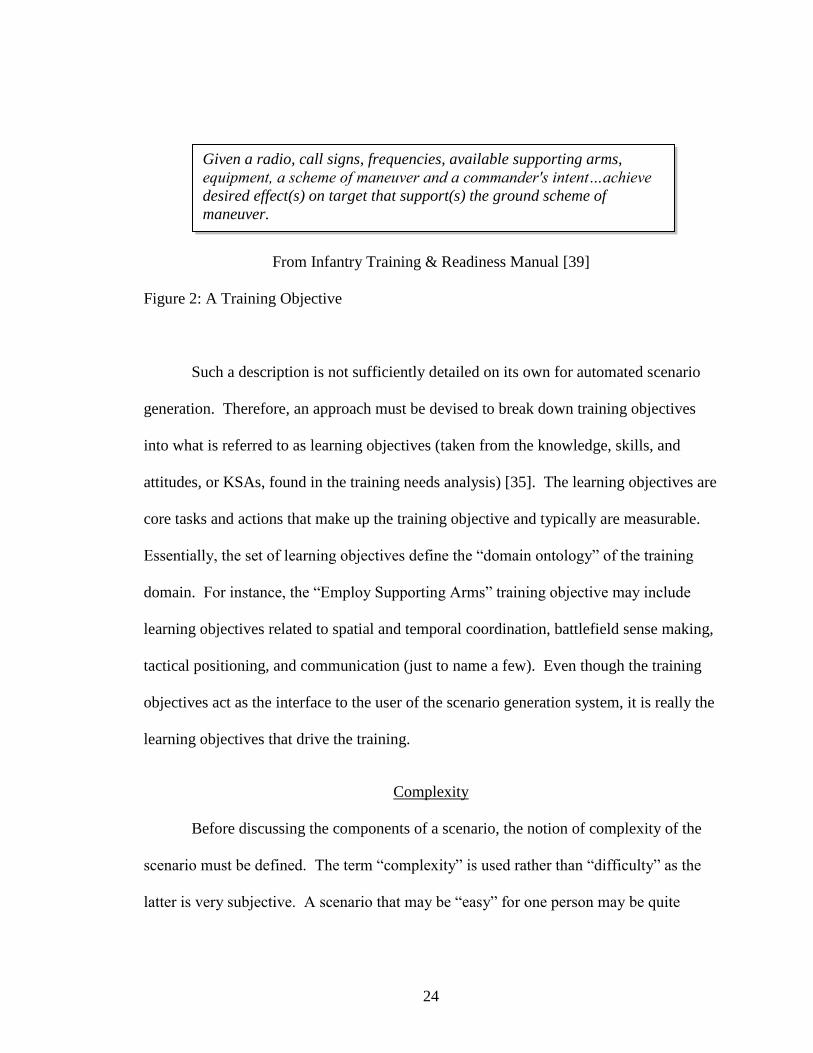
The training objectives in the military’s T&R manuals typically have broad
definitions. For example, Figure 2 from the Marine Corps Infantry T&R Manual
describes training objective “0302-FSPT-1302: Employ Supporting Arms” [39].
24
From Infantry Training & Readiness Manual [39]
Figure 2: A Training Objective
Such a description is not sufficiently detailed on its own for automated scenario
generation. Therefore, an approach must be devised to break down training objectives
into what is referred to as learning objectives (taken from the knowledge, skills, and
attitudes, or KSAs, found in the training needs analysis) [35]. The learning objectives are
core tasks and actions that make up the training objective and typically are measurable.
Essentially, the set of learning objectives define the “domain ontology” of the training
domain. For instance, the “Employ Supporting Arms” training objective may include
learning objectives related to spatial and temporal coordination, battlefield sense making,
tactical positioning, and communication (just to name a few). Even though the training
objectives act as the interface to the user of the scenario generation system, it is really the
learning objectives that drive the training.
Complexity
Before discussing the components of a scenario, the notion of complexity of the
scenario must be defined. The term “complexity” is used rather than “difficulty” as the
latter is very subjective. A scenario that may be “easy” for one person may be quite
Given a radio, call signs, frequencies, available supporting arms,
equipment, a scheme of maneuver and a commander's intent…achieve
desired effect(s) on target that support(s) the ground scheme of
maneuver.

25
“hard” for another. However, a scenario that has many concurrent activities can be
objectively referred to as “complex.”
Given the use of “complexity,” all that is needed is a representation of a scenario
complexity as well as each facet complexity. In addition, there must be some formula for
combining the different scenario facets into an overall single scenario complexity. Recall
that complexity can be measured as a function of task complexity (including component
complexity and coordinative complexity) and task structure. Dunne et al. developed a
definition of scenario complexity built around these notions, a task framework and
cognitive context moderators [40]. With these aspects defined, the system can now
represent scenario complexity.
Baselines
After training objectives are chosen, the next step is the selection of a baseline.
Baselines define the environmental setting in which the scenario is taking place. It
includes the terrain (possibly, generated itself), time-of-day and weather effects (wind,
rain, snow). Baselines can support the simplest scenarios (since they provide a setting for
the conditions as specified in the training objectives). While they may be in any terrain
(even harsh ones) or in poor illumination or weather, the training objective requirements
will state the need for minimal assets for the scenario itself. Therefore, the scenario will
be simplest in assets although the environmental effects may cause it not to be the
absolute simplest in nature.
Although baselines can support training, these simple scenarios only offer
minimally beneficial training experiences. Since they are so simplistic, baselines only

26
support training the most novice trainees in mostly procedural operations. Baselines lack
variability (other than entity location) and additional complexity. In order to expand
baselines to better support advanced training, additional scenario elements are needed.
Augmentations
How does a baseline represent different environmental conditions? In the
conceptual model, it uses a notion called augmentations. These elements possibly add
complexity to the scenario and can affect aspects of the baseline itself. Examples include
moving a Fire Support Team scenario to night or adding rain. Each of these potentially
adds complexity to the generated scenario (note that the complexity added by an
augmentation is domain dependent; e.g., switching to night would add complexity in a
Fire Support Team task but perhaps not in a non-visual task domain). However, not all
augmentations may be applicable to the chosen training objectives. In addition, some
augmentations may need to be limited. It would make no sense to add a “night”
augmentation to a scenario more than once. Therefore, when augmentations are
specified, they include parameters that better define their use (such as restrictions on the
quantity allowed).
The adding of augmentations to a baseline begins to add complexity to the
training scenario. However, it is important to reiterate that augmentations to baselines
simply change the initial environmental situation. Augmentations will later be used to
enhance vignettes as well, but in different ways.

27
Vignettes
The training objectives and baseline (with or without augmentations) selection
sets the basic initial situation. Vignettes add learning-objective content to the baseline in
order to make a larger (and more complex) scenario. Vignettes are pre-packaged
alterations and/or additions to the scenario that exist in a library for selection.
Scenario vignettes are defined as sets of associated triggers and adaptations.
Triggers are defined as any kind of check or comparison that returns a Boolean (true or
false) value. Triggers may be based simply time-based or be based upon specific events
(e.g. a detonation occurred nearby). When a trigger is determined to be true, its
corresponding adaptation is executed. A trigger could have more than one adaptation
associated with it in which case all adaptations would be executed (serially). Triggers
can also be chained to provide “if-then” type logic or even Boolean “and” logic; we can
even include triggers that provide a branching type mechanism.
Adaptations are alterations made to the current situation within the simulation.
They range from those that provide entity manipulations (create, kill, move, fire weapon)
to those that provide environmental manipulations (reduce rain, raise sun). Their primary
purpose is to adjust the training (cause an event to occur). However, they can also be
used to adapt the scenario in a pre-planned way (provide remediation or add complexity
to the scenario). In addition, they can also be used to repair an exercise. For example, if
a critical entity is killed, then an adaptation can be used to recreate it to facilitate the
completion of the scenario. Since training can be expensive (both in terms of cost and
time), each training opportunity is important and adapting the scenario in this way avoids
28
that exercise from being lost. In summary, adaptations cause changes to occur within the
scenario itself. Together with triggers, they form the basis for adjusting scenarios during
the simulation itself.
Note that the trigger/adaptation scheme also provides an additional capability.
While not the focus of this work, this scheme can also support dynamic scenario
adaptation. This adaptation can work with pre-defined rules (or other machine
intelligence schemes) to create new triggers/adaptations during the running of the
simulation. In other words, the system could create new simulation events to satisfy
instructional needs identified during the exercise. For example, if a trainee accidentally
gets killed (virtually) during an exercise, the adaptation system may detect this (with a
trigger already in place) and dynamically prepare an adaptation that would re-spawn the
trainee (again, so that the training opportunity is not lost). Similarly, if a trainee’s
performance falls outside of a predetermined range, then the system could trigger an
adaptation that escalates the training (e.g., introducing the next training objective) or one
that offers remediation.
Satisfying Requirements
Before the scenario is considered complete in this conceptual model, one
additional step is required. The training objectives, baselines and vignettes may have
specified additional requirements for the scenario. For example, a training objective may
require a target to exist. However, that objective has not specified the type of position of
that target (just that it must exist). These details, the requirements, are left as the final
step.

29
Again, in the conceptual model, requirements can be satisfied either manually, by
a user, or via an automated approach. The types of requirements that may be necessary
are enumerated for each training domain. This allows the system to prompt for the
specification of that requirement type. For example, knowing that a target is required, the
system can prompt for type and position of that entity. Once all requirements are
specified, then the scenario is considered complete.
Review of Concepts
The conceptual model has many elements. In order to help the reader, each is
summarized here. Table 1 describes each concept. Figure 3 shows a diagram that depicts
how elements relate to each other.
Conceptual to Computational
While a conceptual model of a scenario is now complete, this is not yet concrete
enough for building scenarios. The conceptual model must be mapped into a
computational one. The next chapter discusses this mapping in detail.

30
Table 1. Table of Concepts in Conceptual Model.
Concept Definition
Training Objective Higher-level task being trained.
Learning Objective The tasks that underline the training objective.
Related to KSAs. Ultimately, it is these that are
being trained.
Trainee The person being trained.
Profile A table tracking what a trainee has attained;
includes measures of performance of each training
and learning objective.
Performance A measurement of a particular training or learning
objective.
Simulation The tool used to train or practice. Typically, a
virtual environment.
Event An action within the simulation or possibly an
interaction with the trainer/instructor.
Scenario All the elements needed to run a simulation;
represented in this work as a set of facets with
parameters set and requirements satisfied.
Situation A specific snapshot at a precise moment of a
scenario.
Complexity Measure of how complex a scenario or facet is.
Facet A component that makes up a scenario; a baseline,
augmentation, trigger, adaptation or vignette.
Baseline The simplest facet; includes virtual world to use
with environmental parameters. Can also declare
requirements that need to be satisfied. Has a
complexity level.
Augmentation Facet that adds an element to the scenario.
Element can be environmental or a new entity.
Can also override parameters or declare
requirements that need to be satisfied.
Trigger Facet that is a Boolean check on some event (could
be within the simulation or set by the trainer). Can
declare requirements that need to be satisfied.
Adaptation Facet that changes the simulation in some way.
Can override parameters, generate new entities or
manipulate entities. Can declare requirements that
need to be satisfied.
Vignette Set of augmentations, set of triggers and set of
adaptations that represents some sub-scenario.
Facets within the vignette can be chained for
complex actions. Has a complexity level.
Parameter Some value of the scenario; mostly environmental
(e.g. time of day).
Requirement Additional information needed to fully define a
facet.

31
Figure 3: Diagram of Concepts
32
CHAPTER FOUR:
COMPUTATIONAL MODEL
With the conceptual model defined, the idea of automating the scenario
generation can begin to be investigated. However, before a scenario generation system
can be built, the ideas within the conceptual model have to be made more concrete within
a computational model.
Mapping Conceptual to Computational
To map the conceptual model into a computational one, each conceptual
component will be considered and a computational model built to represent it. This
includes how to represent the training objectives, the notion of a scenario complexity, the
baselines and vignettes (in turn, defined in terms of the augmentations, triggers and
adaptations).
Training Objectives
In order to support training objectives, a tiered system is used. Objectives are
mapped into a three-tier hierarchy with levels being a major category, a minor category
and a “code” within the major-minor category. While this maps well into existing T&R
manuals, it also provides a very good, yet simple, approach to mapping training
objectives across all domains. Any given domain can likely be categorized into this
three-tier hierarchy. XML also represents such a hierarchy very well and is used to store
the training objectives in files. Figure 4 shows the XML representing just a single
example training objective.

33
Figure 4: An Example Training Objective
In the figure, note the “requirements” section. This section lists all elements that
must be specified when using this training objective. For example, it specifies that a
“target” must be declared. A target must exist for this training objective but resolution of
its specific parameters can be postponed. This allows the specification of the training
objectives to be more qualitative in nature and, therefore, more flexibly used.
In addition, note the list of learning objectives connected with the training
objective. As mentioned in the previous chapter, the learning objectives are the specific
actions necessary to complete the training objective and are more concrete than the stated
training objectives. Ultimately, these are the actions whose performance is being
measured and are used to gauge the trainee’s abilities.
<objectives>
<major code="INF" filename="INF.png">
<minor code="FSPT">
<objective code="6302">
<name>Conduct FiST Operations</name>
<requirements>
<requirement id="FiST"/>
<requirement id="Target"/>
<requirement id="Artillery"/>
</requirements>
<los>
<lo>Adaptability</lo>
<lo>Integration (Coordiation and Deconfliction)</lo>
<lo>Battlefield Sensemaking</lo>
<lo>Combinated Arms Resource Allocation</lo>
<lo>Rehearsal</lo>
<lo>Intelligence Gathering</lo>
<lo>Asset Sequencing</lo>
<lo>Battlespace Geometry</lo>
<lo>Orientation to Target</lo>
<lo>Information Exchange</lo>
</los>
</objective>
</minor>
</major>
</objectives>

34
Complexity
In order to measure complexity of the various scenario facets as well as the total
complexity of the scenario being created, the notion of complexity must be made
concrete. How to measure complexity and compare vignettes with each other could
easily be a dissertation topic on its own (and, in fact, a colleague is working on this very
topic). For this work, complexity is defined simply as a number in the range of 0 to 100,
inclusive.
Baselines and vignettes are assigned complexity scores by a subject matter expert.
Computationally, regardless of how these scores are computed (whether using the model
by Dunne et al. or another), those values are merely stored in the respective facet
definition. As each facet is added to a constructed scenario, the complexity scores of
each facet are simply summed. This sum is tracked and the overall complexity of the
scenario is enforced to be within a range designated appropriate for the trainee. If a
scenario has a complexity outside the desired range, it is adjusted, accordingly, to reach
the goal.
Baselines
Similar to the training objectives, XML can also be used to store the baselines.
Each baseline contains a name, description, visual database, constructive database, a map,
and reference points to map the world into the databases. In addition, each baseline also
includes a list of training objectives that it is said to “support.” If a baseline supports a
training objective, the baseline will be listed as a possible choice for the user when that
training objective is chosen for training.

35
Baseline definitions also include a list of parameters. These are stored in a
computational structure to represent the environmental augmentations defined in the
previous chapter. Each parameter defines an environmental factor and overrides any
previous setting. Figure 5 shows an example to bring all these concepts together.
The next facet to review is the vignettes. However, before discussing vignettes in
detail, augmentations, triggers and adaptations are first reviewed.

36
Figure 5: An Example Baseline
<baseline type="1001">
<name>29 Palms</name>
<description>29 Palms</description>
<imagefilename>29Palms.png</imagefilename>
<mapfilename>29Palms.png</mapfilename>
<visualdb>\data\terrain\29palms_alpha\archive.txp</visualdb>
<constructivedb>29palms_ver40</constructivedb>
<maprefpoints>
<refpoint>
<worldpoint>
<x>-2349768.0</x>
<y>-4729349.0</y>
<z>3564665.0</z>
</worldpoint>
<pixel>
<x>0</x>
<y>2285</y>
</pixel>
</refpoint>
<refpoint>
<worldpoint>
<x>-2292590.0</x>
<y>-4757691.0</y>
<z>3564186.0</z>
</worldpoint>
<pixel>
<x>2900</x>
<y>2285</y>
</pixel>
</refpoint>
<refpoint>
<worldpoint>
<x>-2279703.0</x>
<y>-4732399.0</y>
<z>3605603.0</z>
</worldpoint>
<pixel>
<x>2900</x>
<y>0</y>
</pixel>
</refpoint>
</maprefpoints>
<supports>
<objective major="0302" minor="FSPT" objective="2302"/>
<objective major="INF" minor="FSPT" objective="6302"/>
</supports>
<parameters>
<parameter name="tod">1500</parameter>
<parameter name="weather">clear</parameter>
<parameter name="windspeed">10</parameter>
<parameter name="winddirection">N</parameter>
</parameters>
</baseline>

37
Augmentations
The discussion of augmentations here refers to those augmentations that would be
part of a vignette and somewhat ignores those specified as part of a baseline. However,
they can have commonalities as all augmentations override parameters (whether defined
in the baseline or vignette). For example, a “night” augmentation could specify the time-
of-day to be at 2:00 A.M. In reality, however, augmentations are really a superset of the
baseline’s parameters. While they can and do change these parameters, they actually do a
lot more.
Augmentations also specify new elements within the scenario. For example, an
“additional target” augmentation may exist to indicate that a second target should be
added to the scenario. Augmentations can also be used to specify other players within the
scenario.
Augmentations are specified by a name, description, a complexity level that
represents how much they add to the scenario, a notion of quantity allowed (again, it
makes no sense to add a “night” augmentation more than once), a set of parameters being
assigned (in the case of a baseline, parameters being overridden) and a set of
requirements. The requirements are exactly like those from the training objective. They
are additional elements that are required for the scenario although their precise
parameters are postponed for later resolution.
Similar to previous facets, XML is also a good representation for augmentations.
In particular, it allows for a variable set of elements (the parameters and requirements)
that may or may not be a part of the augmentation. It also allows for easy editing, which

38
is also a big advantage. Figure 6 shows two augmentations; one focuses on overriding
parameters while the other adds new requirements to the scenario:
Figure 6: Two Example Augmentations
Triggers
Triggers, as defined previously, are simple tests or comparisons that are Boolean
in nature. They are relatively easy to take from concept to computational entity at least
as far as specifying. They include a name, description, and an optional set of
requirements. In this case, the requirements represent the parameters of the Boolean
check itself. For example, a trigger checking to see if an explosion occurred near an
entity needs to have the entity in mind specified. A trigger prompting the instructor
before continuing needs the prompt itself specified. Even a time-based trigger that waits
until some specific time in the exercise is met needs that time specified.
<augmentation type="2001">
<name>Night</name>
<description>Change time of day to nighttime</description>
<imagefilename>night.png</imagefilename>
<complexity>30</complexity>
<quantity>1</quantity>
<parameters>
<parameter name="tod">200</parameter>
</parameters>
</augmentation>
<augmentation type="2002">
<name>Add'l Target</name>
<description>Add an additional target to the scenario</description>
<imagefilename>addlTarget.png</imagefilename>
<complexity>30</complexity>
<quantity>10</quantity>
<requirements>
<requirement id="Target"/>
</requirements>
</augmentation>

39
XML is, again, a good candidate for this representation. Figure 7 shows an
example of a trigger of a detonation occurring near a given position.
Figure 7: An Example Trigger
Adaptations
Adaptations are the “result” component of a trigger and describe the effects of the
trigger occurring. In practice, they are very similar to triggers, however. They include a
name, description, an optional set of requirements and an optional set of parameters.
Here, the requirements represent the parameters of the object of the action. For example,
an adaptation that moves an entity must declare which entity to move and to what
location. The parameters represent changes to the environmental setting. For example,
an adaptation that wants to change the time-of-day must specify that new time.
Again, XML is a good candidate as it provides an easy mechanism for optional
information. Figure 8 shows two examples of adaptations; one that includes a
requirements list and one that alters parameters:
<trigger type="3003">
<name>Detonation Nearby</name>
<description>Activated when detonation near a position</description>
<imagefilename>detonationNearby.png</imagefilename>
<requirements>
<requirement id="Position"/>
</requirements>
</trigger>

40
Figure 8: Two Example Adaptations
Vignettes
Vignettes consist of a name, description, additional complexity value, a list of
training objectives that they support (exactly like the baselines) and a tree of facets. The
facet tree is made up of augmentations, triggers and adaptations. The tree-like fashion
allows a powerful mechanism of building up larger structures. For example, an “and”
condition can be represented by placing a trigger under another trigger. An “or”
condition is represented by placing two triggers side-by-side at the same level in the tree.
By expanding this tree, the vignette can become fairly expressive.
Due to the tree nature of vignettes, XML is the perfect representation (and really
drove the use of it elsewhere). The facet tree simply refers to previously defined
augmentations, triggers and adaptations as nodes within the tree. Figure 9 shows a
vignette for moving a target based upon instructor cue (and possibly a second time on a
second cue).
<adaptation type="4003">
<name>Move Entity</name>
<description>Causes entity to move to a given position</description>
<imagefilename>moveEntity.png</imagefilename>
<requirements>
<requirement id="EntityRef"/>
<requirement id="Position"/>
</requirements>
</adaptation>
<adaptation type="4006">
<name>Make Daylight</name>
<description>Changes time of day to daytime</description>
<imagefilename>makeDaylight.png</imagefilename>
<parameters>
<parameter name="tod">1500</parameter>
</parameters>
</adaptation>
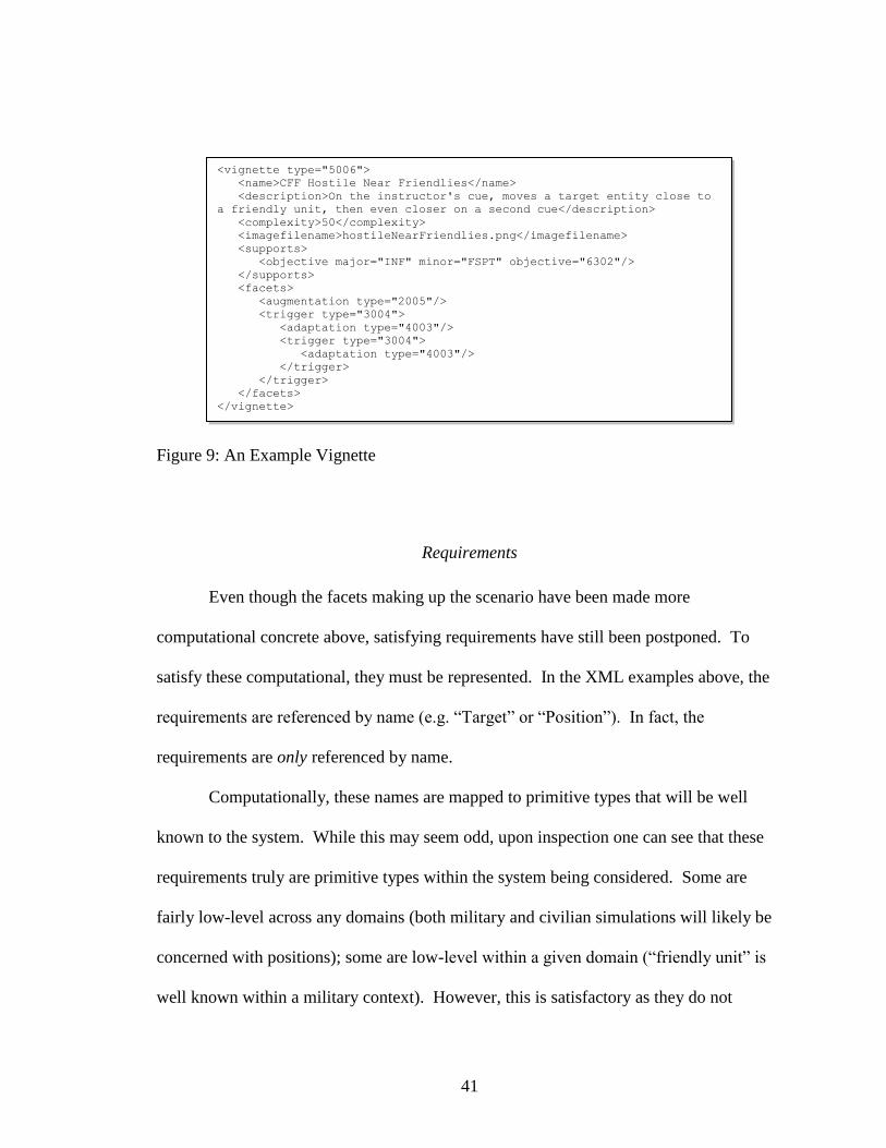
41
Figure 9: An Example Vignette
Requirements
Even though the facets making up the scenario have been made more
computational concrete above, satisfying requirements have still been postponed. To
satisfy these computational, they must be represented. In the XML examples above, the
requirements are referenced by name (e.g. “Target” or “Position”). In fact, the
requirements are only referenced by name.
Computationally, these names are mapped to primitive types that will be well
known to the system. While this may seem odd, upon inspection one can see that these
requirements truly are primitive types within the system being considered. Some are
fairly low-level across any domains (both military and civilian simulations will likely be
concerned with positions); some are low-level within a given domain (“friendly unit” is
well known within a military context). However, this is satisfactory as they do not
<vignette type="5006">
<name>CFF Hostile Near Friendlies</name>
<description>On the instructor's cue, moves a target entity close to
a friendly unit, then even closer on a second cue</description>
<complexity>50</complexity>
<imagefilename>hostileNearFriendlies.png</imagefilename>
<supports>
<objective major="INF" minor="FSPT" objective="6302"/>
</supports>
<facets>
<augmentation type="2005"/>
<trigger type="3004">
<adaptation type="4003"/>
<trigger type="3004">
<adaptation type="4003"/>
</trigger>
</trigger>
</facets>
</vignette>

42
change once in existence for a given domain. It is enough to enumerate the possible
requirements that will need to be addressed and develop a method for doing so. The
exact method used in this work will be reviewed in later sections.
Manual Scenario Generation
Before getting into automating scenario generation, it is useful to review a manual
approach. A user first selects the training objectives and complexity desired; ideally,
these may also be selected automatically based on a trainee’s profile, but they are
selected in a manual approach. The user then selects a baseline (which can include
environmental augmentations), which sets the initial situation of the exercise. Then, zero
or more vignettes are selected. Each facet adds a complexity cost to the total scenario
with the system enforcing the desired complexity level. Finally, the user satisfies the
requirements of training objective and facet that remain unspecified. Figure 10 shows an
example of a scenario (with a single vignette) and how the elements help form a scenario.
Figure 10: Scenario Example

43
The goal of an automated approach is to replace many, or all, of these steps.
Chapter 2 reviewed some previous methods for creating scenarios and also some aspects
from other domains (e.g. interactive storytelling) that are valuable to maintain in
generated scenarios. In the next chapter, procedural modeling is reviewed in more depth
and Functional L-systems are presented as a solution applying the computational model
developed here to automated scenario generation.
44
CHAPTER FIVE:
PROCEDURAL SCENARIO GENERATION
Given the need for scenario generation mentioned earlier, there has been a large
interest in generating such scenarios automatically. Performing the process by hand is a
very expensive proposition and causes a lack of scenarios for use in training. Those
hand-created scenarios that do exist are re-used and not adapted in any way for an
individual trainee.
With the conceptual model defined and translated into computational structures,
automatic scenario generation can now be addressed. As seen earlier, past approaches
have used seeded, enumerated and heuristic approaches. While all have been valuable
efforts, they also have their weaknesses. In this work, an alternative, procedural
modeling techniques, is pursued.
Procedural modeling refers to a technique in computer graphics of using a set of
rules to create models, textures and/or animations for a scene or part of a scene. It is used
when manual creation of the component would be cumbersome or expensive. Procedural
rules are stored that can be used to create (or even re-create) the component as needed. A
particle system for representing smoke is one example. Rather than modeling a set of
spheres by hand to create a smoke plume, it is programmed within a software system and
simulated automatically.
Procedural Modeling Process
Procedural modeling has existed since the start of computer graphics. Indeed, the
first graphical systems generated everything procedurally with the notion of content-

45
based systems coming later. First, simple geometry was generated with color and texture
following. Indeed, in the 1980s procedural modeling for realistic textures (such as
marble) was developed [40]. In addition, in 1989 Pixar’s RenderMan system and its
shading language is credited with greatly expanding procedural modeling [40].
Developed since 2009, Minecraft is an online independent game that uses a large
procedurally generated terrain with various terrain types [42].
The major benefit for modern procedural modeling is known as data amplification
[43]. A description of the data to be generated is stored rather than the data itself.
Typically, the description is smaller than the data and can be used to generate the data
relatively quickly. Sometimes this can be beneficial for memory storage. Moreover, it
can also provide a mechanism for generation of similar, yet different, versions of the
data. This is a key aspect in our work and will be used in our scenario generation.
A related issue to data amplification is self-similarity. This concept is the basis
for many procedural generation techniques. Many things in the world appear self-similar
at different scales – either exactly self-similar or so called statistically self-similar [43].
Exactly similar objects look exactly the same when any region is enlarged; statistically
similar objects that contain noise appear the same on the average when enlarged. Clouds
and branches on a tree are two common examples of self-similar objects.
Procedural Modeling Methods
Over the years many basic approaches have been developed for procedural
modeling. These include fractals, L-systems, Shape Grammars and Functional L-

46
systems. We review each of these methods here before reviewing specific systems
related to our approach.
Fractals
Fractals are based on geometric shapes that possess self-similarity. They contain
subdivided parts, each of which is a copy of the whole shape. The term fractal was
coined by Benoit Mandelbrot [43]. The boundary of the Mandelbrot set is a popular
example of a fractal. The “Koch Snowflake” is another popular fractal that begins with a
single equilateral triangle with the “middle third” of each side repeatedly replaced with
an equilateral “bump” [44].
Fractals are generated in three ways [45]. Escape-time fractals define a
recurrence relation in some point-space (the Mandelbrot set is an example). Iterated
function systems use a fixed geometric replacement method (the Koch Snowflake being
the prime example). Random fractals use stochastic (rather than deterministic) methods
that generate objects such as fractal landscapes.
Within nature and virtual environments, fractals represent items such as clouds,
plants, river networks and mountain ranges. Lightning, blood vessels and crystals can
also be defined using fractals. In addition, fractals have been applied to areas such as
analysis of music [46] and seismology [47].
L-systems
Lindenmayer Systems, or L-systems as they are more commonly known, are
based on formal grammars [48]. They are often used to model the growth of plants and,

47
hence, are used to generate virtual plants. L-systems use a recursive definition, which
leads to a self-similarity quality and makes them related to fractals. As opposed to formal
grammars that operate in a sequential fashion, rewriting just one symbol or substring at
each step, L-systems progress from one string to the next by rewriting all variables
simultaneously.
L-systems are defined by a set of variables, a set of constants, a start state of the
system and a set of production rules. For example, Figure 11 shows Lindenmayer’s
original system for the growth of algae (reproduced from [49]):
(a) (b)
Figure 11: An Example of an (a) L-system and (b) one string it produces
In order to graphically render the output of L-systems, each alphabet letter must
be connected to a drawing action. For example, a letter could mean “move forward”,
“turn 45 degrees” and such.
Extended L-systems
Parish and Müller have built a rule-based system for creating cities named
CityEngine [50]. Their approach is based on what they call Extended L-systems. These
A
AB
ABA
ABAAB
ABAABABA
ABAABABAABAAB
ABAABABAABAABABAABABA
Variables: A B
Constants: none
Start: A
Rules: A→AB, B→A

48
are L-systems with the parameters set by functions rather than built directly into the rules.
This provides a capability to flexibly change a parameter without having to re-write a
number of rules within the L-system. The steps used in Extended L-systems are as
follows:
1. Run the L-system and find the ideal successor. The parameters within the
modules of the successor are left unassigned.
2. Call a “globalGoals” function that will set the parameters based on overall
global goals. All parameters within the modules are set after this step is
complete.
3. Call a “localConstraints” function that will check the parameters against
any local constraints within the environment. This function can adjust the
parameters or return a “failed” condition if the parameters are not suitable,
yet unadjustable within the constraints of the rules or environment.
Their approach first creates road networks, divides the land between roads into
lots, creates buildings on the lots and then textures the buildings. Image maps that
represent geographical (e.g. elevation maps) and socio-statistical data (e.g. population
centers) can be used as input to the system. For example, Figure 12 shows how image
maps for water, elevation and population density can feed into the road network
generation.

49
From Parish and Müller [50]
Figure 12: Water, Elevation and Population Density Maps Affect Road Networks
Moreover, CityEngine does not consider all roads equal. The notion of highways
and local streets is also supported. Highways connect areas with highly concentrated
populations by scanning the population density input map for peaks. Streets cover the
areas between highways according to local population density (which gives transportation
access to the nearest highway). To find the next population center for a highway, every
road-end shoots a number of rays radially within a preset radius. Population at every
sample point on the ray is then weighted with the inverse distance to the road-end and
summed up. The direction with the largest sum is chosen for continuing the growth and
placing the highway.
CityEngine uses a set of rules for creating road networks. These are as follows:
Basic rule: Simply follow population density (older parts of cities)

50
New York rule: Follows a given global or local angle and maximal length
and width of a single block
Paris rule: Highways follow radial tracks around a center
San Francisco rule: Streets and highways follow route of least elevation
(roads on different height levels are connected by smaller streets)
After the road network is defined, the areas between the roads are split into blocks
and then building lots. This is a relatively straight-forward process given that most lots
are convex and rectangular. An image map can be used to define a maximum building
height in areas to accomplish design goals such as keeping skyscrapers together in one
area.
Building geometry is then created using a stochastic L-system that consists of
transformation modules (scale and move), an extrusion module, branching and
termination modules, and geometric templates [50]. Textures are then procedurally
generated using a grid on each building side as a basis. Location also drives the texture
process with doors appearing on the ground level and slight texture enhancements made
for realism (such as door frames).
CityEngine is impressive and shows the flexibility of procedural modeling
techniques. However, the input it requires (image maps of geographical and socio-
economic data) is limiting in the context of automatic scenario generation. The approach
can likely be altered, though, and the concept of Extended L-systems that use external
functions to set parameters would definitely be useful in future systems.
51
Shape Grammars
Müller et al. developed a method for procedural creation of buildings based on a
notion of shape grammars called CGA Shape [51]. Shape grammars were first used for
architecture by Stiny [52]. However, Müller extended the notion by modeling buildings
with consistent mass models and focusing on application details such as a concise
notation and defining the “most important” rules within a set of rules.
Wonka et al. simplified shape grammars to split grammars, which are based upon
set grammars [53]. Split grammars are based on object replacement with basic objects
being split into multiple terminal objects (or alternatively, replaced by another basic
object). CGA Shape is also based upon set grammars with extensions. The grammar
defines the replacement of lower detail items as well as rules to add, scale, translate and
rotate shapes. Müller argues that while “parallel grammars like L-systems are suited to
capture growth over time, a sequential application of rules allows for the characterization
of structure.” Therefore, as opposed to the parallel replacement used in L-systems, CGA
Shape uses a sequential grammar.
Within CGA Shape, production rules are defined in the form:
id : predecessor : cond successor : prob
where id is a unique identifier for the rule, predecessor is a non-terminal that is to be
replaced by successor and cond is an expression that must evaluate to true for the rule to
be applied (at which time the rule is selected with probability prob). As an example, the
rule:
1 : fac(h) : h > 9 floor(h/3) floor(h/3) floor(h/3) : 1.0

52
would replace the shape fac with three shapes floor if the parameter h is greater than nine
with probability 1.0 (from [51]).
CGA Shape also supports scope rules that use a stack with push and pop
operators, which allows the transforming of one object without affecting others. In
addition, a split (subdivision) rule exists to split an object into a set of smaller shapes
(such as a side of a building into multiple floors), and a repeat rule exists to tile a shape
(such as placing multiple windows along one floor). There are also rules for working
with 2-D objects to allow operations such as extruding.
One final aspect of CGA Shape is snapping. Since a building is often composed
of multiple shapes, grammar rules are included for the creation of invisible snap lines.
These snap lines are used by other shapes within the building to snap their geometry to
create a better appearance. For example, a skyscraper using tapered sections will still
align all of its floors rather than each shape deciding the split of its floors independently.
CGA Shape is fundamentally built upon the concept of shape replacement rather
than the L-system concept of string replacement. It should be noted, however, that CGA
Shape’s major application is the creation of models from imagery and blueprints. The
focus is on re-creating actual locations as opposed to creating various buildings with
similar qualities.
Functional L-systems
Marvie, Perret and Bouatouch developed a system based on a modified L-system
to render building exteriors [54]. Known as FL-systems (or Functional L-systems), they
define each component as one of two types of functions. The first, those that do not

53
return a value, replace a typical L-system terminal symbol (and are known as terminal
functions). They are used to generate or modify the content of an object that is given as a
parameter to the function. The second type of function describes those that return a value
that contains a parameter and are used to create objects. When these functions exist
within rule parameters, they are executed and their return values are used as the
parameters within the rule.
Fundamentally, each terminal or non-terminal includes a function that is executed
to generate necessary components within the rule system. Compare this to the
architecture in CityEngine where global and local constraint functions are called. FL-
systems call functions at each sub-derivation step whereas CityEngine only calls the
constraint functions after a derivation is complete. The FL-system not only controls
which rules are to be applied, but can also stop the derivation process associated with the
rewriting mechanism based on the function return values.
An important advantage of FL-systems is that they map to scene graphs and
object creation and manipulation very easily. Furthermore, FL-systems support an
iterative mechanism to generate nodes in the derivation in a breadth-based method (rather
than a recursive mechanism that would produce objects in a depth-based manner).
Functional L-systems and Scenario Generation
This work focuses on the use of FL-systems for automated scenario generation.
Users will still be prompted for the training objectives to be used and a desired
complexity range. After that, however, an automated system will choose a baseline and a
set of vignettes to create the scenario.
54
FL-systems, in particular, are well suited for providing such a system and offer
two major advantages. First, the extra power provided by having terminal functions (as
opposed to terminal symbols) allows higher complexity decision making by the rule
system. Details about the training objectives chosen as well as the trainee profile can be
used by the terminal functions in their decision-making processes.
The second advantage is in the terminal functions allowing the postponement of
resolving requirements. This allows the basic rule system to be written with fewer rules.
The parameters of the requirements can be satisfied within a terminal function.
The limitations of FL-systems include the additional work necessary to author the
rule systems and the need to write the terminal functions themselves. However, both
limitations are minimal in that each is only performed once per training domain. When
another training domain is desired (a rehabilitation scenario, for example), then a new set
of rules and terminal functions must be written.
Grammar Representation
In order to use FL-systems for scenario generation, a representation for the rules
(grammar) must first be developed. The basic rule structure from CGAShape is used
[51]:
id : predecessor : cond successor : prob
where id is a unique identifier for the rule, predecessor is a non-terminal that is to be
replaced by successor and cond is an expression that must evaluate to true for the rule to
be applied (at which time the rule is selected with probability prob).
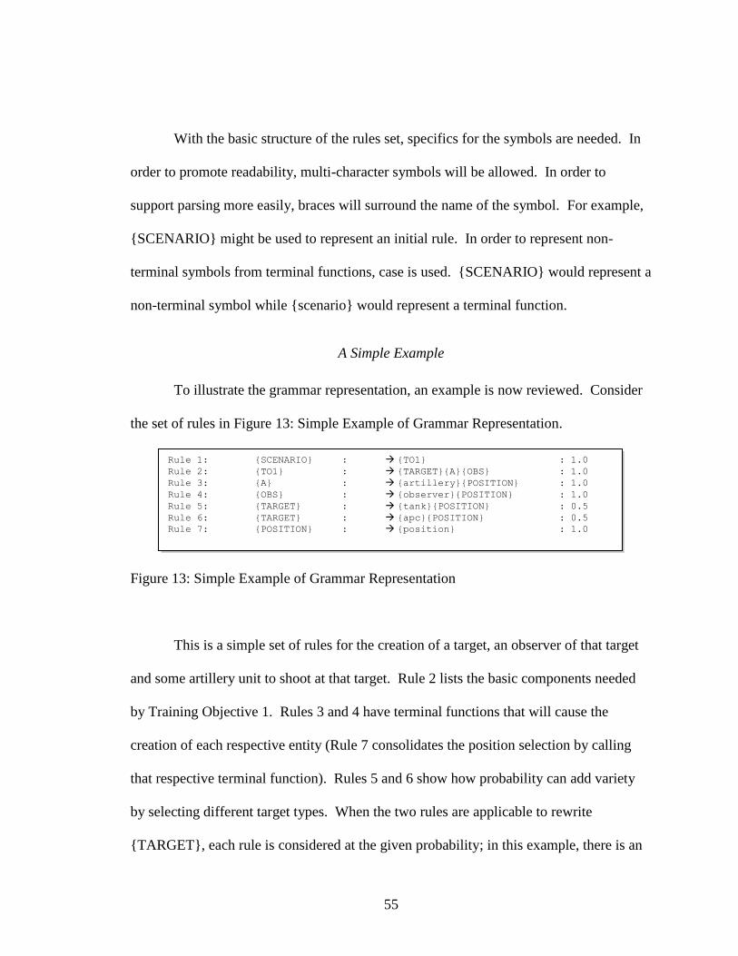
55
With the basic structure of the rules set, specifics for the symbols are needed. In
order to promote readability, multi-character symbols will be allowed. In order to
support parsing more easily, braces will surround the name of the symbol. For example,
{SCENARIO} might be used to represent an initial rule. In order to represent non-
terminal symbols from terminal functions, case is used. {SCENARIO} would represent a
non-terminal symbol while {scenario} would represent a terminal function.
A Simple Example
To illustrate the grammar representation, an example is now reviewed. Consider
the set of rules in Figure 13: Simple Example of Grammar Representation.
Figure 13: Simple Example of Grammar Representation
This is a simple set of rules for the creation of a target, an observer of that target
and some artillery unit to shoot at that target. Rule 2 lists the basic components needed
by Training Objective 1. Rules 3 and 4 have terminal functions that will cause the
creation of each respective entity (Rule 7 consolidates the position selection by calling
that respective terminal function). Rules 5 and 6 show how probability can add variety
by selecting different target types. When the two rules are applicable to rewrite
{TARGET}, each rule is considered at the given probability; in this example, there is an
Rule 1: {SCENARIO} : {TO1} : 1.0
Rule 2: {TO1} : {TARGET}{A}{OBS} : 1.0
Rule 3: {A} : {artillery}{POSITION} : 1.0
Rule 4: {OBS} : {observer}{POSITION} : 1.0
Rule 5: {TARGET} : {tank}{POSITION} : 0.5
Rule 6: {TARGET} : {apc}{POSITION} : 0.5
Rule 7: {POSITION} : {position} : 1.0

56
equal probability that the target will be satisfied with either a tank or an armored
personnel carrier. Probabilities are assigned by the rule author and can be weighed
equally (as in this case), or the choices may be biased, if desired. Obviously, the set of
rules can be made much more complex to provide even greater capabilities and variety
than this simple example can show.
A More Complex Example
The simple example above does not show off passing parameters to the terminal
functions. As written, it would likely place all entities in the same location. For a more
complex example, consider the set of rules in Figure 14.
This example demonstrates many of the powerful computational additions that
FL-systems provide. In addition, it is a more complete example than the first. Rule 2
demonstrates the selection of a baseline (in this case, there is only one to choose from so
it is chosen with probability 1.0). Rules 3 and 8 show examples of training objectives
and entity elements, respectively, being satisfied in parallel. Rules 4 to 7 show the
“conditional” component restricting the use of the rules (these rules should only be used
if the corresponding training objective has been chosen by the user).
Rules 9 to 12 demonstrate parameters being passed into terminal functions. Note
that the same terminal function can be re-used simply by passing different parameters.
The parameters, in these cases, refer to either known entity types to the scenario
generation system or known positional concepts. The positions can either be areas
declared as part of the baseline or even computed by a knowledge computational system.
For example, Fire Support Teams are typically up on a hill overlooking a valley. These

57
hills can either be declared as part of the baseline record or could be intelligently
determined by a function performing some terrain analysis.
Figure 14: More Complex Example of Grammar Representation
Rules 13 and 14 show scenario variability. These two rules choose, with an equal
chance, two different targets that appear differently and could have different weapon
ranges, etc. In addition, rules 20 and 21 show further variability. Here, there is an
unequal chance of a fixed wing aircraft being chosen over a rotary wing aircraft as an air
asset. Each is used differently by the Fire Support Team so this provides slightly
different training opportunities. Rule 24 shows an example of an environmental
parameter being set.
1: {SCENARIO} : {BASELINE}{OBJS} : 1.0
2: {BASELINE} : {baseline}(“29Palms”) : 1.0
3: {OBJS} : {TOCFF}{TOCAS} : 1.0
4: {TOCFF} : selected(“TOCFF”) {FIST}{TARGET}{IDF} : 1.0
5: {TOCFF} : selected(“TOCFF”) {FIST}{TARGET}{TARGET}{IDF} : 1.0
6: {TOCFF} : selected(“TOCFF”) {FIST}{TARGET}{IDF}{NIGHT} : 1.0
7: {TOCAS} : selected(“TOCAS”) {FIST}{TARGET}{ADA}{AIR}{IDF} : 1.0
8: {FIST} : {FOM}{FOA}{FAC}{FTL} : 1.0
9: {FOM} : {type}(“fom”){position}(“fistloc”) : 1.0
10: {FOA} : {type}(“fom”){position}(“fistloc”) : 1.0
11: {FAC} : {type}(“fom”){position}(“fistloc”) : 1.0
12: {FTL} : {type}(“fom”){position}(“fistloc”) : 1.0
13: {TARGET} : {type}(“btr80”){position}(“targetloc”) : 0.5
14: {TARGET} : {type}(“bmp2”){position}(“targetloc”) : 0.5
15: {IDF} : {MORTAR} : 0.5
16: {IDF} : {ART} : 0.5
17: {MORTAR} : {type}(“mortar”){position}(“mortarloc”) : 0.5
18: {ART} : {type}(“artillery”){position}(“artloc”) : 0.5
19: {ADA} : {type}(“zsu”){position}(“adaloc”) : 1.0
20: {AIR} : {AV8B} : 0.75
21: {AIR} : {COBRA} : 0.25
22: {AV8B} : {type}(“av8b”){position}(“fixedloc”) : 1.0
23: {COBRA} : {type}(“cobra”){position}(“rotaryloc”) : 1.0
24: {NIGHT} : {tod}(“0300”) : 1.0
58
Analysis
In the second example, rules 8 to 24 provide basic components of all Fire Support
Team scenarios. Therefore, these rules would be re-used as support for larger quantities
of training objectives was provided. Additional rules of the type seen in rule 2 could be
added to support alternate baselines. Furthermore, rules similar to rules 3 to 7 could be
added to support other training objectives. Only if additional basic components were
necessary (such as friendly ground units represented) would rules similar to rules 8 to 24
be added.
Rules similar to rules 3 to 7 are the equivalent of a user selecting a vignette.
When one of these rules is applied, it is equivalent to the user manually selecting a
vignette and adding it to the scenario. The right-hand side of the rule roughly represents
the scenario facets (augmentations, triggers and adaptations) of a vignette. In addition,
the terminal functions are roughly equivalent to satisfying the requirements in the manual
approach. They decide the type and other data (e.g. position) much like a user does when
satisfying the requirements manually.
The use of probability allows for variations in the scenario. In rules 4 to 7 the
probability is used to randomly select one vignette over another. In rules 13 and 14 a
target is randomly chosen. By using multiple rules to represent different, but equivalent,
decisions, the system provides variation while still maintaining a qualitative equality
between different scenarios. If two or more rules are qualitatively equivalent, they will
be written together and the probability range split across them. In other words, the rules,
themselves, maintain the qualitative equivalence of the generated scenarios.
59
The parallel nature of L-systems (and FL-systems) allows for consideration of
multiple “vignette rules” or in the satisfaction of “requirements.” In the former, each rule
that represents a vignette can be explored simultaneously. One is then chosen based upon
the relative probability. Rules 4 to 6 in the previous example illustrate this. However,
some complications can arise as well.
One issue is tracking total scenario complexity. The system must carefully track
total complexity so as to avoid the situation where two vignettes contain an appropriate
complexity increase but both together would result in a scenario with too high a
complexity. Rule 3 in the previous example will consider two training objectives in
parallel. If both objectives are selected, this results in four rules being considered in
parallel (rules 4 to 7). Three of them (rules 5 to 7) are mutually exclusive based upon
matching non-terminals and the probability distribution of each rule. However, rule 4
and the selected rule from among rules 5 to 7 could potentially both apply in parallel.
This is essentially a race condition. Therefore, while multiple vignettes can be evaluated
in parallel, some control on the decision process is necessary. Rather than encoding this
into every rule selection, the system tracks this itself and enforces selection of a single
vignette before evaluating a next step. Unfortunately, this is a weakness of the L-system
approach to scenario generation. However, this occurs only at the vignette selection
stage and the benefits of such an approach still suggest that it works well for scenario
generation overall.

60
Implementation
With the new approach of FL-systems to automated scenario generation complete,
an actual implementation was created to verify the design. In addition, having an actual
system allows the verification of its ability to create adequate scenarios. The next chapter
delves into the details of the implementation.

61
CHAPTER SIX:
SCENARIO GENERATION FRAMEWORK
With the scenario defined, computational model created and an approach for
automated scenario generation completed, this chapter ties everything together.
A Scenario Generation System
As part of validation for this research, the Procedural Yielding Techniques and
Heuristics for Automated Generation of Objects within Related and Analogous
Scenarios, or PYTHAGORAS, was designed and implemented. However,
PYTHAGORAS is not a new scenario generation system in itself. Rather,
PYTHAGORAS is a scenario generation engine. By “scenario generation engine” we
mean a system that provides the common functionalities across all (or more precisely, all
conceived of in this research) potential scenario generation systems within a single
foundation for all (or at least most) training environment scenarios (much like a game
engine provides the common needs of games).
Whether military or another domain, there are many capabilities needed in a
scenario generation system. For example, display and selection of training objectives is a
function that must exist across any scenario generation system. In addition, support for a
graphical user interface and potentially other interfaces (such as three-dimensional
rendering) could be included. On the other hand, there are also some features that may be
specific for each domain and the ability to support that is also necessary. To address
these issues PYTHAGORAS was constructed to have a fundamental architecture of
common functionalities coupled with a plug-in architecture for specific domain features.

62
Plug-in Architecture
The plug-in architecture of PYTHAGORAS allows users to write their own new
capabilities to include in their scenario generation system. Furthermore, they could even
write a set of plug-ins to create a scenario generation system for their own, new domain.
Figure 15 shows a diagram of the PYTHAGORAS architecture with example modules in
place for what exists for the CAN-oriented Objective-based Generator of Scenarios
(COGS) [55]. COGS will be covered in more detail later in this document (at this point,
it is enough to know that it is a specific scenario generation system built upon
PYTHAGORAS).
Figure 15: COGS Modules within PYTHAGORAS
As suggested, such an architecture allows other modules to be loaded to
essentially create a new scenario generation system. Indeed, PYTHAGORAS supports
all sorts of general scenario generation systems. For example, one could build such a
system for cognitive rehabilitation where a patient practices making breakfast in a kitchen
setting. In this case, friendly units and targets may not be required, but a coffee maker
and spoon might be [56]. PYTHAGORAS supports this by allowing a different set of

63
plug-ins and rules to be loaded; essentially, an entirely new application is created built
upon PYTHAGORAS. In addition to providing flexibility, the plug-in architecture also
provides the capability not to load a feature if desired. In this manner, building systems
to generate scenarios in other domains can be performed at reduced cost and with reduced
resource requirements.
Core
The core system ties everything together. It handles the loading and initialization
of plug-ins and can provide a common database of key information if desired. The core
actually is built to handle multiple threads of plug-ins, with each plug-in assigned to its
given thread group. Besides making the code more flexible and easier to implement, the
thread system also allows PYTHAGORAS to more easily work on processors with
increasing number of cores.
A common “Configuration for PYTHAGORAS Initialization” (or .cpi) file
provides the core with instructions for initialization of the system. It includes basic
information for the specific application being run on top of PYTHAGORAS as well as a
list of plug-ins (with their corresponding threads) to load and initialize. It is a bit of a
simplification, but it is this “cpi” file that defines how each PYTHAGORAS application
is different from all others.
Message System
In order to allow the core functions and the plug-in modules to communicate, an
event system was built. Events can be both issued and received by each component.

64
Some events are well-known, meaning that all components may need to process these
(such as when training objectives are selected) while others may be specific to a subset of
modules and all other components will ignore them.
PYTHAGORAS actually contains two different types of messages. The first are
passed from plug-in to plug-in. When a plug-in is first initialized, it registers for the
types of messages in which it is interested. As of now, registration is only performed by
type; however, the system is open to allow registration by other forms (such as by
origination point of the messages). When a plug-in issues a message, a copy of it is
placed into a queue for the receiving plug-in to retrieve.
The second form of messages used in PYTHAGORAS is sent from a plug-in to
the core. These are less used than the first form but are still quite important. For
example, the user interface plug-in might issue the “quit” message to indicate to the core
that the user wishes to exit the program.
This approach also allows each plug-in to be very loosely coupled. A key feature
of this loose coupling is that it provides a very easy method to explore alternative
approaches. For example, different plug-ins for handling scenario complexity or
automated generation can be implemented and simply loaded at different times in order
to do comparison studies between the various approaches.
As discussed earlier, complexity is modeled as a simple value between 0 and 100,
inclusive. If a higher fidelity complexity model is desired, the complexity plug-in can
simply be re-implemented without affecting the rest of the system. In addition, a plug-in

65
to explore shape grammars could easily be pursued by switching it for the FL-system
plug-in.
Review of Key Plug-ins
Among all the plug-ins in PYTHAGORAS, some are key components required
for its functionality. For example, the “gui” plug-in handles all elements associated with
the graphical user interface (GUI) and supports dynamic registration of the scenario
facets. The GUI plug-in also handles interface issues related to the user satisfying
scenario requirements and contains the drawing window for the scenario tree.
The Scenario Editor plug-in handles the tracking of all selected scenario facets
(baselines and vignettes) and their relation with each other (e.g. the scenario tree). It is
also responsible for the loading and saving of scenarios (both complete and incomplete).
It is the organizer of the scenario itself and collects all the data together for output.
The Facet Library plug-in handles reading the facets from an XML file and
instantiating them within the system. This includes sending data to the GUI plug-in
about each facet. Data is also sent out that details the parameters and requirements for
each facet. The Logic System plug-in receives the data about the facets from the Facet
Library plug-in and handles tracking all the requirements declared by selected training
objectives, baselines and vignettes. It also enforces whether all requirements have been
satisfied and, therefore, whether the scenario is ready for exporting.
66
Authoring
PYTHAGORAS also contains an “authoring” plug-in where the user may select
augmentations, triggers and adaptations in order to define a new vignette. Once the
vignette tree is built, the complexity is set for the entire vignette and then training
objectives supported by the new vignette are selected. Essentially, this is precisely the
reverse process (step-wise) of creating a scenario; Facets are selected, then a complexity
set and then training objectives chosen. The new vignette is then transmitted to the Facet
Library plug-in where it is saved for later use.
As part of authoring, PYTHAGORAS also supports the complexity definition
step as a plug-in. This allows various research pursuits in the area of vignette
complexity. Different methods for setting the complexity of a vignette can be
implemented and simply loaded in place of each other here for evaluation. For example,
the complexity could be defined as easily as popping up a GUI element to ask for a value.
However, it also could include a task and sub-task review of the vignette itself that
defines parameters of a complexity formula [57].
Plug-in for Automated Scenario Generation
Finally, the Generator plug-in handles all the automated generation functions.
Here, FL-systems (or Shape Grammars) are used to select baselines and vignettes for
addition to the scenario. This plug-in reads and processes the rule system and sends data
to the Scenario Editor and Logic System plug-ins based upon the scenario facets selected.
Note that the advantages of the messaging system in use here. The generator plug-in

67
sends the exact same messages that would be sent if the user were performing the
selection and requirements satisfaction step manually.
COGS
COGS is the first application built upon PYTHAGORAS. It provides a scenario
generation system for Fire Support Teams (FiST) which coordinate indirect fire and
close-air support against targets. COGS itself uses the PYTHAGORAS core and its set
of “core” plug-ins.
Figure 16 shows an example of COGS in use. The steps to creating a scenario are
listed in the bottom left and are “checked off” as each step is completed. The scenario
facets (baselines and vignettes) for the chosen training objective are shown on the left-
hand side, the facet tree of the current scenario appears in the middle, and the
requirements that need definition are shown on the right-hand side.
Figure 16: An Example of COGS

68
COGS provides a good example of the PYTHAGORAS engine. However, the
configuration for each of plug-ins is specific to FiST exercises and this configuration is
essentially what makes COGS what it is. The configuration file for the Facet Library in
COGS has its own list of training objectives, baselines and vignettes. The
“requirements,” defined by these facets and satisfied by the Logic System in manual
mode and the Generator in automatic mode, are the low-level parameters for the FiST
domain. For example, “entity type” and “position” are two such requirements.
Does It Work?
COGS is an automated scenario generation system that creates scenarios based
around Fire Support Team training objectives. However, while it creates scenarios, they
may not be correct or provide training value. An analysis of the scenarios is needed.

69
CHAPTER SEVEN:
A TURING TEST FOR SCENARIOS
In order to evaluate the scenario generation system, a review by subject matter
experts was created. The goal was to create an unbiased comparison between human-
generated scenarios and those created by the scenario generation system.
The Turing Test
Turing posed whether computers could perform well in the imitation game (a
game where two hidden players, one male and one female, are interrogated through only
written communication by a third player, who must determine which is the male and
which is the female) [58]. In the imitation game, player A intentionally tries to fool the
interrogator while player B tries to help. Turing wondered whether a computer could be
programmed to play the role of player A. This question has become a key concept in the
area of artificial intelligence.
Over time this question has generalized into an interpretation where one of the
two players is a computer and one is a human, and the interrogator must identify them
accordingly (again, only using written communication). Note that the computer must
only sufficiently imitate a human; not necessarily actually think. This thought
experiment is now commonly called the Turing Test.
A Scenario Turing Test
Given the goal of the scenario generation system is to produce scenarios of
sufficient quality, an evaluation was performed to verify its performance. A Turing Test

70
approach was used. Given a training objective and complexity level desired, a human
subject matter expert creates a scenario. Then, the scenario generation system also
creates a scenario for the same training objective and complexity. These two scenarios
are then presented to separate, and independent, subject matter experts for review and
analysis.
While the goal of this Scenario Turing Test is to have the automated system be
indistinguishable from human subject matter experts, additional analysis was also
performed. Questions were posed that evaluated the quality of the scenarios (both
human-created and system-created) and also that probed at the conceptual understanding
of the automated system itself.
For each scenario pair the reviewers were asked whether one of the pair was
easily identifiable as created by a human. If so, the reviewer was then asked to identify it
and give a measure of level of confidence in that identification. The reviewer was then
asked to give an overall assessment (grade) for each of the scenarios in the pair.
The last element of studying the quality of the scenarios asked the reviewers to
identify the strongest and weakest points for each scenario. Any omissions were also to
be listed and how each scenario might be improved. Finally, the reviewers were asked if
any of the omissions might indicate a weakness in how it was generated.
To assess the ability for the automated system to generate relevant scenarios, the
reviewers were asked for their feedback on the model of baselines and vignettes. This
included how this model may or may not correspond with the practice of professionals in
their field. Delving deeper, the reviewers were also asked to give their thoughts on the

71
vignettes and their representation as a set of triggers and adaptations, including how well
it can capture the important features needed in their field.
Expert Review
In the review here, two training objectives were identified. Given the example
domain of Fire Support Teams, one objective primarily based upon Indirect Fire (IDF)
was identified and also one upon Close Air Support (CAS). Specifically, these were:
1. Integrating, coordinating and de-conflicting close air support, indirect fires
and maneuver to attack selected targets.
2. Using doctrinal control procedures successfully to coordinate and control
attacks from CAS platforms on a visually marked target.
Both “novice” and “expert” complexity level scenarios were produced for each
training objective. This resulted in four pairs of scenarios being evaluated in a 2x2 study.
For the human-produced scenarios, scenarios that were recently added to the new
Instructional Support System (ISS) of the U.S. Marines Deployable Virtual Training
Environment (DVTE) were used. These scenarios have limited distribution to date and
the SMEs had not yet seen them. The scenario generation system then was used to
produce corresponding scenarios; the output was then re-plotted in the Joint Semi-
Automated Forces (JSAF) application so that the map displays would match the human-
produced ones.
The four scenario pairs were randomized and presented to five, independent,
subject matter experts as a multi-page questionnaire. These experts include a Sergeant
who regularly performs these IDF and CAS tasks within the U.S. military, a Lieutenant

72
Colonel and two Majors who are instructors (at two different locations) within the U.S.
military that teach these tasks, and a retired Lieutenant Colonel who is well-versed in
these tasks. Of the five, four returned the document (one of the Majors did not).
Analysis
The four subject matter experts performed a thorough review, which can be
examined from various directions. As a simple measurement, each reviewer was asked
to, literally, grade each scenario. Looking at the data as a whole, the human-generated
scenarios resulted in a “grade point average” (GPA) of 2.625 (between a C+ and a B-).
This is somewhat surprising since they were based on scenarios in use today; however,
the result may be more based on the write-up of the scenarios than the scenario
themselves (discussed below). Similarly, the computer-generated scenarios resulted in a
GPA of 2.375 (also between a C+ and B-). While lower than the human-generated
scenarios, it is within a half grade. More so, given the reasons offered by the reviewers,
this difference can likely be reduced.
Looking at the results in the 2x2 study arrangement provides some additional
details (see Table 2). The IDF-Novice condition had a much greater spread in the GPA
measurements (3.667 for human vs. 2.333 for computer) while the others were much
closer. Concerns about the computer-generated scenarios were expressed about the
aircraft missing ordnance and sensor details, the lack of a ground maneuver element and
the relatively few targets. In contrast, the human scenario contained the ground
maneuver element and used the fire elements well in support of that ground maneuver
element.

73
Table 2. GPA Results of 2x2 Study.
IDF CAS
Novice Human: 3.667
Computer: 2.333
Human: 2.000
Computer: 2.000
Expert Human: 3.083
Computer: 3.167
Human: 1.750
Computer: 2.000
In evaluating the automated system qualitatively, the reviewers most noted that it
lacked a ground maneuver element as a part of the scenarios, particularly regarding the
Indirect Fire scenarios. While the scenarios generated by the automated system do lack
this element, it is largely due to the author’s lack of military expertise and not the system
itself. It is a straight-forward matter to add creation of this entity to the rules. Doing so
will allow the automated system to provide the lacking ground maneuver element.
Regarding the Close Air Support scenarios, both the human-generated and
computer-generated scenarios received low marks (GPA of 1.875 for the human-
generation scenarios; 2.0 for the computer-generated). In both cases, this had little to do
with the placement of the elements, but in the lack of information on sensors and
ordnance. The reviewers indicated that both are critical to proper scenario execution as it
drives what actions the trainee and can perform (or not perform). For example, an
aircraft with laser-guided bombs makes the use of indirect fire unnecessary. Similar to
the missing ground maneuver element, additional rules can provide the ordnance and
sensors to the appropriate entities. Ultimately, while the computer-generated scenarios
do perform as well, or better, than the human-generated scenarios, both sets need
improvement.

74
It is interesting to note that the computer-generated expert scenarios perform
better than the corresponding human ones (albeit the scores are very close). The reason is
likely the perception that the computer-generated scenarios provided more options to the
trainees as far as approaches to take in the exercise. That is likely desirable for an expert-
level scenario, but perhaps not for a novice scenario. It very well may be related to an
increased complexity as well (where more tasks or events would possibly lead to more
options).
Feedback from the reviewers on the automated system approach focused more on
suggestions for how the process could be performed rather than on the system itself. This
is likely due to their expertise in training and their vision for the goal of offering the best
training possible. Comments fall into two categories. First, a more precise call-out of the
specific training objective (T&R event in the U.S. Marines) was suggested, including the
training goals. For example, is the goal to conduct sequential or simultaneous actions?
Once this is understood, the elements of the scenario will flow. The automated system
uses this technique conceptually but it may need to be made more explicit.
Related to the first category, the second focuses on the ordnance and sensor
capabilities of aircraft (already alluded to earlier). Given this domain (Fire Support
Teams), the ordnance and sensor capability can drive the scenario much more than any
sort of geographic concerns (geography is still a secondary concern, though). It is
interesting that both the human and computer scenarios did not make these elements
explicit. Since they do not necessarily affect the entity placement, it may have simply
been overlooked. However, it is clear that it must be explicit. This leads to a future

75
research item: not only generating the scenario, but also the write-up of the scenario,
complete with training objectives and training goals.
Interestingly, the active-duty military reviewer that was lowest in rank thought
more highly, qualitatively, of the computer-generated scenarios and felt they provided a
good variety of options (as opposed to only allowing a single course of action). The
instructors were less satisfied; the retired Lieutenant Colonel was most critical and
focused on command-and-control concerns. The lower rank reviewers were also active
certified Joint Terminal Attack Controllers (JTACs) as compared to those focused on
instruction.
A final analysis of the scenarios concerns the Scenario Turing Test. Each
reviewer was questioned as to which scenario within the pair was human-generated.
Across all scenarios, the reviewers correctly chose the human-generated scenario
approximately 75% of the time. However, the reason given all but a few times was on
the lack of a maneuver element. This is correctable with some additional rules in the
automated system. The one other reason identified concerned the write-up of the
scenario itself (the phrase “providing over watch” was used in one single description and
this alerted a single reviewer).
If the data is analyzed within the 2x2 study arrangement, a number of interesting
results are available as well (see Table 3). The CAS scenarios were all identified
correctly and with relatively high confidence levels for the most part. Based upon
comments, the reviewers indicated real world range specifics as the primary factor in
their identification. With improved terminal functions in the automated system (i.e.,
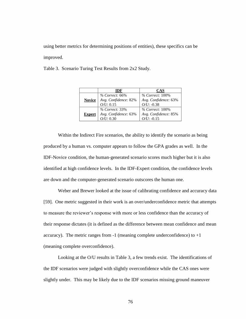
76
using better metrics for determining positions of entities), these specifics can be
improved.
Table 3. Scenario Turing Test Results from 2x2 Study.
IDF CAS
Novice
% Correct: 66%
Avg. Confidence: 82%
O/U: 0.15
% Correct: 100%
Avg. Confidence: 63%
O/U: -0.38
Expert
% Correct: 33%
Avg. Confidence: 63%
O/U: 0.30
% Correct: 100%
Avg. Confidence: 85%
O/U: -0.15
Within the Indirect Fire scenarios, the ability to identify the scenario as being
produced by a human vs. computer appears to follow the GPA grades as well. In the
IDF-Novice condition, the human-generated scenario scores much higher but it is also
identified at high confidence levels. In the IDF-Expert condition, the confidence levels
are down and the computer-generated scenario outscores the human one.
Weber and Brewer looked at the issue of calibrating confidence and accuracy data
[59]. One metric suggested in their work is an over/underconfidence metric that attempts
to measure the reviewer’s response with more or less confidence than the accuracy of
their response dictates (it is defined as the difference between mean confidence and mean
accuracy). The metric ranges from -1 (meaning complete underconfidence) to +1
(meaning complete overconfidence).
Looking at the O/U results in Table 3, a few trends exist. The identifications of
the IDF scenarios were judged with slightly overconfidence while the CAS ones were
slightly under. This may be likely due to the IDF scenarios missing ground maneuver

77
elements on the system-generated scenarios while both sets of CAS scenarios had issues
identified. Therefore, there were more obvious signs to identify the IDF scenarios
(although the metric does show a slight overconfidence as well). The CAS scenarios
were identified with underconfidence which may show the decision coming down to
more of a guess (albeit an educated one). Some of the comments connected with the
measures indicate this as well. Overall, the metric is fairly reasonable; a score of zero
being perfect, the reviewers got within 0.38 (absolute value) in the worst case.
While the global look at the data shows the automated approach to perform
satisfactorily, looking at the 2x2 study provides some interesting results. Furthermore,
evidence at the possibilities of the approach begins to show. Some scenarios were
satisfactory with the reviewers and outscored the corresponding human ones. However,
others show the lacking elements of the current rules and how they need to be improved.
Summary
The Scenario Turing Test provides a compelling review of the scenarios
generated by the automated system. While the reviewers were not fooled in many cases
about which scenarios were human-generated, the causes expressed are easily
addressable. While the number of reviewers was limited, the grades assigned to each set
of scenarios are competitive, illustrating that an automated approach to generate relevant
scenarios has potential. In addition, the reviewers provided very important feedback
(some of which also applies to the human-generated scenarios) that will help drive future
scenario generation effort.

78
CHAPTER EIGHT:
CONCLUSION AND DISCUSSION
This dissertation explored the notion of automatic scenario generation. In most
cases, current training tends to re-use a small library of existing libraries over and over
again. The goal in this work was to create, using procedural techniques, qualitatively
similar, yet still different, scenarios.
Contributions
Six major contributions were presented that move scenario generation and
training forward.
1. A conceptual model of scenarios built around training objectives (and
learning objectives), complexity, baselines and vignettes was created. The
model allows for elements of the scenarios to be conceptualized and built
into “building blocks” for the scenario.
2. A computational model to represent scenarios and scenario facets, built
around XML, was also developed. Having a concrete representation of
the conceptual model is necessary in order for a computer to have any
chance of actually creating a scenario.
3. Procedural modeling techniques, including Functional L-systems, were
shown to be appropriate and effective for scenario generation. The
addition of terminal functions gives a computational increase in power that
is well-suited to the decisions that need to be made by such a system.
Parameters can be set and requirements satisfied. The parallel nature of
79
FL-systems is useful, but can also cause some issues during the vignette
selection stage.
4. A generic engine for scenario creation, PYTHAGORAS, was built. The
use of a plug-in architecture for the engine allows the relatively simple
creation of other scenario generation systems for other domains. In
addition, common aspects of scenario generation systems can be shared
and re-used.
5. A first system, COGS, was built on top of the engine to explore the
automatic creation of scenarios for Fire Support Teams. The system
support both manual and automatic methods, which allows instructors to
override the automated system, if desired. COGS allowed the exploration
of the basic concepts and exercised the concepts above to illustrate they
also work in practice.
6. A scenario “Turing Test” was created and used to analyze the scenarios
automatically created by the system and, ultimately, the system itself.
Being able to create scenarios at all is not enough. The scenarios must be
on par with human-created scenarios and be acceptable by subject matter
experts. The test asked reviewers to compare human-generated scenarios
with system-generated scenarios with the goal of them being
indistinguishable.
80
Review
How does this work compare to previous works and how well does it satisfy the
approach for scenario-based training? MSDL used an XML approach but it was very
much tied to military scenarios. The approach taken in representing the scenario facets in
this thesis generalizes to multiple domains (military and civilian). By restricting the
computational model to more generic concepts (e.g., “Entity”) that have parameters
rather than a more specific tag (e.g., “Tank”), other domains for training are possible.
The approach taken in this work also leverages the best lessons learned from past
work. The building blocks (scenario facets) follow a similar approach taken by RRLOE
and ISAT, allowing for pre-approval of concrete items by subject matter experts (which
simply will enhance acceptance and use). In addition, the approach allows for a model of
scenario complexity that is both concrete and manageable. Each facet contributes to the
total scenario complexity and can be measured accordingly.
Regarding leveraging the training domain (such as in the work by Pffefferman),
the work described here does not make direct use of such knowledge. However, doing so
is a better approach in that the domain knowledge is leveraged in the rule authoring
within the FL-systems rather than deeply within the system itself. The rule system
provides an abstract layer above the software for representing and using such intimate
knowledge. This further generalizes the software approach taken.
Variety of scenarios is provided through randomization, similar to the approach
by Di Domenica et al. By including random probabilities within the rule definitions of
the FL-system, various scenarios can be created. However, qualitatively equivalent rules

81
support the need for creating qualitatively similar scenarios (while still providing for
variety). The parallel nature of FL-systems also allows for the consideration of multiple
vignettes (further supporting variety).
In order to support improved training, the domain ontology approach of FEAST is
leveraged into learning objectives stored with the training objectives. The learning
objectives are truly the tasks being trained and tracking such objectives (and potentially
including metrics to measure performance of them) is important to support improved
adaptive training. The approach taken in the XML files employed here allows for
learning objectives for various training domains (both military and civilian) to be stored
flexibly and leveraged into trainee profile data for future considerations in training tasks.
Interactive storytelling focuses on driving events during an exercise to gain a
particular experience for the user. While this is closer to during-exercise scenario
adaptation, the trigger-based approach within the vignettes allows for this flexibility in a
pre-planned sense. Triggers support both pre-conditions and persistent pre-conditions.
Ultimately, however, the approaches used in interactive storytelling will be most valuable
in work concerning dynamic scenario adaptation.
The use of Functional L-systems provides a system with the necessary expressive
power for evaluating scenario complexity, tracking parameters necessary for selection of
scenario baselines and vignettes, and satisfying their requirements. The use of terminal
functions, in particular, allows higher-level reasoning at each stage, including checking
the scenario itself and looking up aspects of the trainee’s profile. Indeed, this additional
computational capability can provide additional expressive power to past procedural

82
modeling work as well. For example, the Parish and Müller CityEngine work could
leverage terminal functions as opposed to global and local constraint functions. As with
all approaches, however, some authoring (in this case, rules and terminal functions) is
necessary.
Regarding the components leading to improved scenario-based training, the
approach taken in this work satisfies four of them and supports the fifth. The vignettes,
themselves, store the embedded triggers necessary while the training objectives link in
the clearly-defined goals (it should be noted, however, that these goals should be
expressed within the mission brief as well). As alluded to previously, the randomness of
the FL-system provides the necessary approach to providing a variety of qualitatively
similar scenarios. In addition, complexity is supported through tracking it across the
scenario as within each scenario facet. Regarding psychological fidelity, the FL-system
allows for the creation of realistic scenarios although this is dependent on the rule author
as well as the simulators actually in use.
Closing the Loop
Recall that experts make decisions by leveraging a repository of experiences and
use that collection to compare situations, which suggests that expertise depends upon
exposure to a varied set of experiences [10]. Multiple, varied scenarios help trainees
generalize their understanding and to be able to adapt it to new situations [8]. Varied
scenarios allow trainees to try different courses of action within a single scenario and also
to practice an intended course of action across different scenarios [9]. In addition,

83
scaffolding theory promotes learning by providing supports initially, which are then
slowly removed as trainees develop learning strategies on their own [60].
Due to these notions, when creating an automatic scenario generator, the use of
what was learned in previous exercises is important as a basis for the next scenario. For
example, if a trainee makes a particular mistake, the next scenario may want to focus
more on that task, or it may want to provide additional support for that training goal.
This approach “closes” the loop on the training sequence and creates an adaptive
automatic scenario generator. The results of the After Action Review (AAR) can be fed
into the scenario generation system and could result in alterations to the rules used by the
procedural modeling system. Figure 17 shows the new training sequence with the dashed
line representing the “closing of the loop” in data flow.
Figure 17: Training Sequence with Automatic Scenario Generation.
84
The automatic scenario generator now feeds the exercise with the database, entity
placement and entity scripting. It also generates the scenario that is given to the
trainee(s) so that a plan can be developed. The scenario generator is adaptive based on
the data from the after action review that is fed into the trainee profile.
Additional Testing
While the system presented in this dissertation has a scholarly basis and has
shown potential, additional testing should still be performed. The initial expert review
was focused on feedback of the basic approach so it had limited participation. However,
the Scenario Turing Test can be repeated using a larger audience with the initial issues
addressed (lacking ground maneuver element, ordnance and sensors). In addition, the
scenario size itself (4 types of scenarios; IDF vs. CAS and Novice vs. Expert) could be
expanded as well. There are a multitude of possible training objectives and a larger
quantity of complexity levels could be used.
A number of other interesting alterations are also possible. For example, using
scenarios created by novices may provide useful results by illustrating important issues
that may be common mistakes. Review by experts from another area might also provide
an interesting alternative perspective.
Other Scenario Elements
This work has focused on scenario generation using simple selection of baselines
and vignettes (and satisfying each facet’s requirements). There are actually a large
number of elements of a scenario including the terrain, buildings, object placement and

85
behaviors. Output from after action review can also drastically help drive the scenario
generation for training process. In this section, each is reviewed as future explorations
for automatic scenario generation. These elements could be subjects of many research
efforts; moreover, each can have a direct impact on scenario generation and training and,
therefore, the topics are very ripe for such pursuits.
Terrain
The generation of terrain could also use a procedural approach and work exists
that have used such an approach [42][61][62][63][64]. The key element will be the
necessary control to drive the generation as needed. An urban scenario might need a
relatively level area for a town and city and will likely be near a river. However, a “call
for fire” scenario would likely be away from population centers (although urban “close
air support” is becoming an area of interest). Roads and other culture are also a
consideration.
Buildings
When it comes to building exteriors, the use of shape grammars is very effective
and provides good control. One issue, however, is in the generation of building interiors.
Only a few works in this area have been published and none have the control necessary
for an automatic scenario generator [65][66].
Object Placement
Objects within a scenario also need to be generated. They can be placed
throughout the terrain and also represent furniture inside buildings. Scenarios built
86
around empty rooms are not effective training for many skills. However, when
procedurally placing furniture, some concept of the room being built is required to be
understood by the rules being used. In a living room, the couch should face the television
and not face right up against the wall, for example. In addition, the concept of proper
spacing also needs to be incorporated (you do not want the couch completely preventing
people from getting to the other half of the room).
Object Generation
A related notion for objects is in object generation. In other words, procedural
generation of objects could also be performed. Within a building, the furniture itself
could be procedurally generated rather than a model library used. This would allow
objects to be created that fit into a given culture.
Behaviors
While entity placement has its issues, scripting the computer-generated entities
will be challenging on its own. This element has largely been ignored in this work.
However, a number of behaviors can be procedurally suggested (such as a civilian
attacking unexpectedly or maybe falling ill suddenly); feeding them to the system
simulating those entities will be an issue, though. The scripting could be generated in an
XML-based file that can be run through a translator to an appropriate simulation system
(e.g. agent-based system).

87
Textual Description
The final step in the automatic scenario generation system is a textual description
of the scenario suitable for distribution to the trainee(s). While this may seem a bit out of
place, it is the final step in having an automated scenario system for training. Some form
of template can likely be used in which the system can fill in necessary information.
After Action Review Analysis
While not an element to be generated, a final piece that could be added to improve
the scenario generation system is to better use analysis from previous exercises to drive
generation of a scenario. The current system relies on scenario complexity to drive the
creation of a scenario. It is assumed that the trainee’s past performance will be used in
selecting the requested complexity. However, the system could be better tuned. If a
military infantry squad routinely has poor rear security, the scenario could be adjusted to
help train the unit to overcome such a deficiency (perhaps by altering the opposition
entity placement accordingly).
As mentioned at the start of the chapter, this analysis and its resulting data is what
“closes the loop” on the training cycle. By completing this feedback loop, training
systems improve along with the trainees. They adapt as the trainee progresses.
Adaptive Training
Adaptive training avoids the "one size fits all" model that typically exists.
Scenarios can be created that fulfill a specific trainee's needs. This dissertation starts
down the path to creating a computational approach to adaptive training. Scenarios,

88
adapted to the trainee(s), are built using the procedural Functional L-systems and based
upon training objectives and complexity. Additional elements such as those mentioned in
this chapter can be added.
Improving complexity measures will further add to better adaptive training.
While the concept of “complexity” is more objective than “difficulty,” scoring each
baseline and vignette to assign them complexity values is not a trivial activity. The
number of sub-tasks within the activity is a factor; however, a notion of sub-task
coordination is also one. An activity with many sub-tasks required to be completed in
parallel is likely more complex than one with sub-tasks performed serially. However,
cannot an “expert” load balance better than a “novice?” Clearly, additional study on
complexity is necessary.
In addition to scenario generation, adapting the scenario during the training
exercise will further push forward intelligent, adaptive training. Whether due to
performance (good or bad) or functional problems (e.g., getting the aircraft shot down),
scenarios can adapt to enhance the effectiveness of the training for the trainees.
There is a very old notion that you should not train specifically for the test [1].
Pre-exercise scenario generation and during-exercise scenario adaptation are steps to
address that notion.

89
APPENDIX A:
SCENARIO TURING TEST QUESTIONNAIRE

90
Reviewer: __________________ Thank you for agreeing to review scenarios! In this document, four pairs of scenarios are presented. Within each pairing, one is created by a subject-matter expert and one is created by a computer system. They are not identified in any way, however (e.g. you will not be told which is created by the subject-matter expert and which is created by a computer system). The computer system uses a notion of a scenario created from a “baseline” and a set of “vignettes.” The baseline includes a terrain selection and assumes essentially perfect environmental conditions (clear skies, high noon). The vignettes are then selected to add complexity to the scenario until the scenario reaches a desired level (novice, intermediate, advanced). For example, a vignette could add an additional target, an enemy air defense or alter the time-of-day to nighttime. For this review, you will be presented with two scenarios of a similar complexity that both should address the given training objective. Questions regarding the two scenarios are then posed and we greatly appreciate your responses! Finally, at the very end we ask a couple of overall conceptual questions and we would also appreciate your response to these. Please answer each question by entering your reply into the box after each question (you can either edit directly within Microsoft Word, or feel free to print the document and handwrite your answers). Your responses will be kept anonymous to all except for Mr. Glenn Martin, Senior Research Scientist & Lab Director at the University of Central Florida’s Institute for Simulation & Training, who will be receiving the responses. When you are done, please either e-mail the completed document to [email protected] or fax it to Mr. Glenn Martin at (407) 882-1319. Again, many thanks for taking your time and helping out! It really does help us make better training tools!
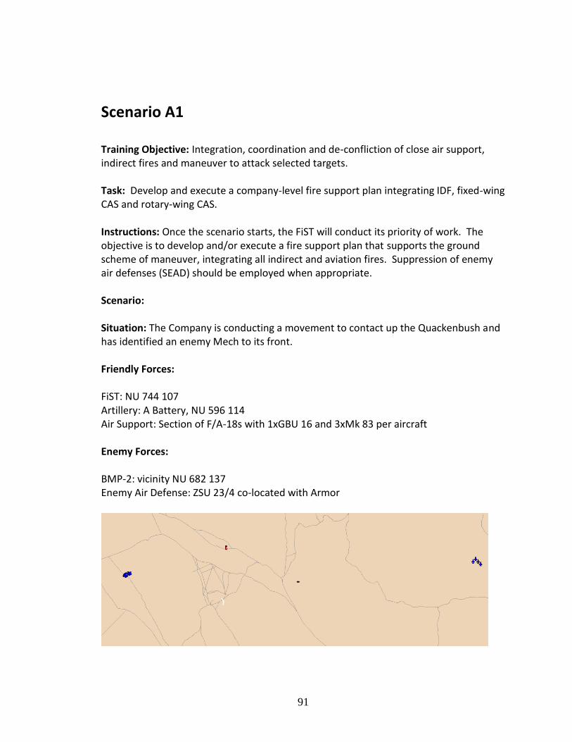
91
Scenario A1 Training Objective: Integration, coordination and de-confliction of close air support, indirect fires and maneuver to attack selected targets. Task: Develop and execute a company-level fire support plan integrating IDF, fixed-wing CAS and rotary-wing CAS. Instructions: Once the scenario starts, the FiST will conduct its priority of work. The objective is to develop and/or execute a fire support plan that supports the ground scheme of maneuver, integrating all indirect and aviation fires. Suppression of enemy air defenses (SEAD) should be employed when appropriate. Scenario: Situation: The Company is conducting a movement to contact up the Quackenbush and has identified an enemy Mech to its front. Friendly Forces: FiST: NU 744 107 Artillery: A Battery, NU 596 114 Air Support: Section of F/A-18s with 1xGBU 16 and 3xMk 83 per aircraft Enemy Forces: BMP-2: vicinity NU 682 137 Enemy Air Defense: ZSU 23/4 co-located with Armor

92
Scenario A2 Training Objective: Integration, coordination and de-confliction of close air support, indirect fires and maneuver to attack selected targets. Task: Develop and execute a company-level fire support plan integrating IDF, fixed-wing CAS and rotary-wing CAS. Instructions: Once the scenario starts, the FiST will conduct its priority of work. The objective is to develop and/or execute a fire support plan that supports the ground scheme of maneuver, integrating all indirect and aviation fires. Suppression of enemy air defenses (SEAD) should be employed when appropriate. Scenario: Situation: The Company is conducting a movement to contact up the Quackenbush and has identified an enemy Mech platoon to its front. Friendly Forces: FiST: NU 669 092 Artillery: A Battery, NU 691 061 81mm Mortars: NU 681 094 Company Lead Trace: NU 667 093 Air Support: Section of F/A-18s with 1xGBU 16 and 3xMk 83 per aircraft Enemy Forces: Armor Platoon (3xBMP 1/AT-3): vicinity NU 658 130 Enemy Air Defenses: SA-14s co-located with Armor Platoon

93
Questions Regarding Scenarios A1 & A2: Please discuss your thoughts on the pairs of scenarios that you reviewed.
1. As we informed you at the start, one of each pair of scenarios was generated by a human, and one by our system. In each case, was one of them easily identified as the human-generated scenario? If so, which one? What is your level of confidence in your identification (e. g. 90% sure; 99% sure; where 50% would mean you feel that you're totally guessing).
2. What is your overall assessment of the relative quality of the two scenarios in each pair?
E. g. "I would give A1 an A-, and A2 a D+". If you prefer a numeric scale, then use A=4.0, B=3.0, C=2.0, D=1.0 and F=0.
3. For each scenario, what are its strongest and weakest points? Were there any obvious
omissions that seemed to you to clearly indicate some weakness in the process by which it was generated? What were those omissions and how could the scenario be improved?
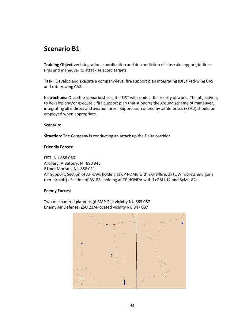
94
Scenario B1 Training Objective: Integration, coordination and de-confliction of close air support, indirect fires and maneuver to attack selected targets. Task: Develop and execute a company-level fire support plan integrating IDF, fixed-wing CAS and rotary-wing CAS. Instructions: Once the scenario starts, the FiST will conduct its priority of work. The objective is to develop and/or execute a fire support plan that supports the ground scheme of maneuver, integrating all indirect and aviation fires. Suppression of enemy air defenses (SEAD) should be employed when appropriate. Scenario: Situation: The Company is conducting an attack up the Delta corridor. Friendly Forces: FiST: NU 888 066 Artillery: A Battery, NT 890 945 81mm Mortars: NU 858 011 Air Support: Section of AH-1Ws holding at CP ROME with 2xHellfire, 2xTOW rockets and guns (per aircraft). Section of AV-8Bs holding at CP HONDA with 1xGBU-12 and 3xMk-82s Enemy Forces: Two mechanized platoons (6 BMP-2s): vicinity NU 865 087 Enemy Air Defense: ZSU 23/4 located vicinity NU 847 087

95
Scenario B2 Training Objective: Integration, coordination and de-confliction of close air support, indirect fires and maneuver to attack selected targets. Task: Develop and execute a company-level fire support plan integrating IDF, fixed-wing CAS and rotary-wing CAS. Instructions: Once the scenario starts, the FiST will conduct its priority of work. The objective is to develop and/or execute a fire support plan that supports the ground scheme of maneuver, integrating all indirect and aviation fires. Suppression of enemy air defenses (SEAD) should be employed when appropriate. Scenario: Situation: The Company is conducting an attack up the Delta corridor. Friendly Forces: FiST: NT 867 997 Artillery: A Battery, NT 890 950 81mm Mortars: NU 892 012 Company Lead Trace: NU 878 005 Air Support: Section of AH-1Ws holding at CP ATHENS with 2xHellfire, 2xTOW rockets and guns (per aircraft). Section of AV-8Bs holding at CP MAZDA with 1xGBU-12 and 3xMk-82s Enemy Forces: Two mechanized platoons (6 BMP-1s with AT-3s): vicinity NU 874 031 Enemy Air Defense: SA-13 located vicinity NU 873 040

96
Questions Regarding Scenarios B1 & B2: Please discuss your thoughts on the pairs of scenarios that you reviewed.
1. As we informed you at the start, one of each pair of scenarios was generated by a human, and one by our system. In each case, was one of them easily identified as the human-generated scenario? If so, which one? What is your level of confidence in your identification (e. g. 90% sure; 99% sure; where 50% would mean you feel that you're totally guessing).
2. What is your overall assessment of the relative quality of the two scenarios in each pair?
E. g. "I would give A1 an A-, and A2 a D+". If you prefer a numeric scale, then use A=4.0, B=3.0, C=2.0, D=1.0 and F=0.
3. For each scenario, what are its strongest and weakest points? Were there any obvious
omissions that seemed to you to clearly indicate some weakness in the process by which it was generated? What were those omissions and how could the scenario be improved?
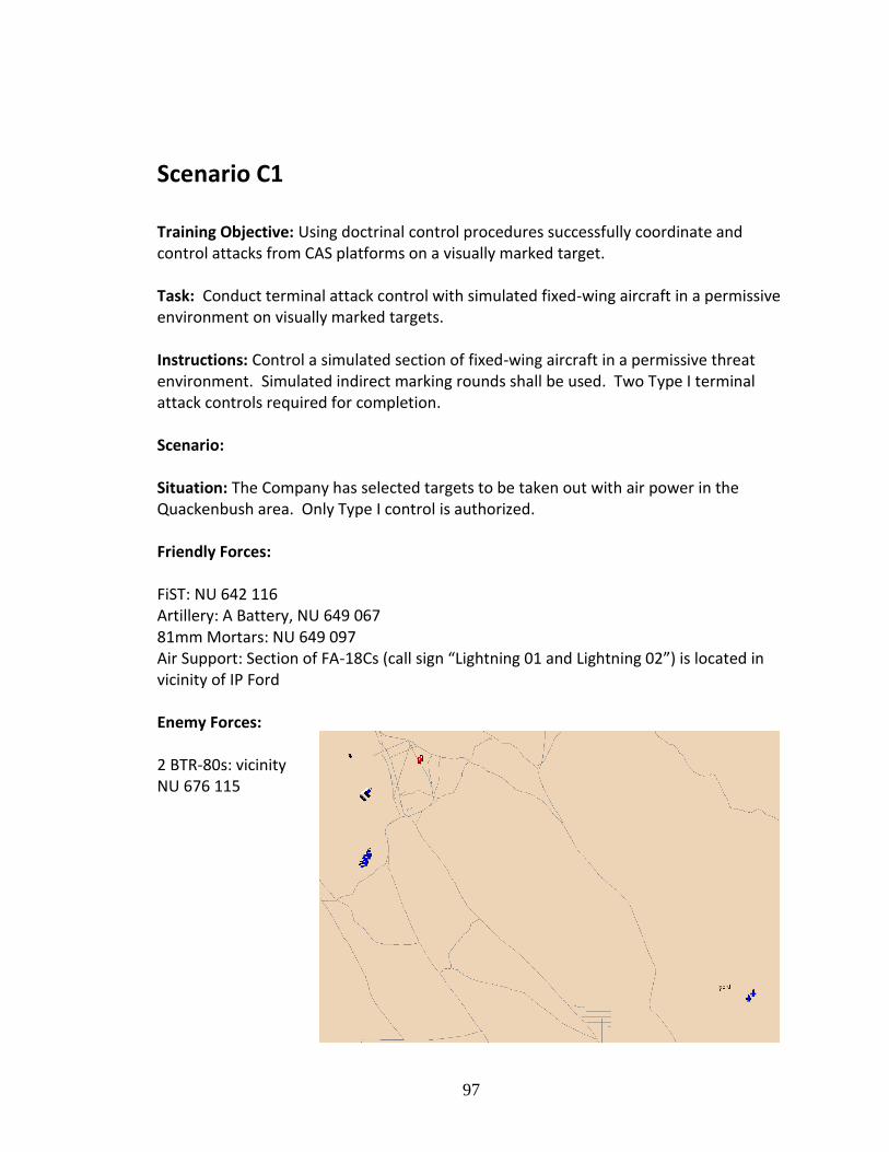
97
Scenario C1 Training Objective: Using doctrinal control procedures successfully coordinate and control attacks from CAS platforms on a visually marked target. Task: Conduct terminal attack control with simulated fixed-wing aircraft in a permissive environment on visually marked targets. Instructions: Control a simulated section of fixed-wing aircraft in a permissive threat environment. Simulated indirect marking rounds shall be used. Two Type I terminal attack controls required for completion. Scenario: Situation: The Company has selected targets to be taken out with air power in the Quackenbush area. Only Type I control is authorized. Friendly Forces: FiST: NU 642 116 Artillery: A Battery, NU 649 067 81mm Mortars: NU 649 097 Air Support: Section of FA-18Cs (call sign “Lightning 01 and Lightning 02”) is located in vicinity of IP Ford Enemy Forces: 2 BTR-80s: vicinity NU 676 115

98
Scenario C2 Training Objective: Using doctrinal control procedures successfully coordinate and control attacks from CAS platforms on a visually marked target. Task: Conduct terminal attack control with simulated fixed-wing aircraft in a permissive environment on visually marked targets. Instructions: Control a simulated section of fixed-wing aircraft in a permissive threat environment. Simulated indirect marking rounds shall be used. Two Type I terminal attack controls required for completion. Scenario: Situation: The Company has selected targets to be taken out with air power in the Quackenbush area. Only Type I control is authorized. Friendly Forces: FiST: NU 672 092 Artillery: A Battery, NU 707 075 81mm Mortars: NU 679 093 Air Support: Section of FA-18Cs (call sign “Lightning 01 and Lightning 02”) is located in vicinity of IP Dodge Enemy Forces: 1 BTR-80: vicinity NU 676 115 1 BTR-80 with Dismounted Infantry: vicinity NU 675 114

99
Questions Regarding Scenarios C1 & C2: Please discuss your thoughts on the pairs of scenarios that you reviewed.
1. As we informed you at the start, one of each pair of scenarios was generated by a human, and one by our system. In each case, was one of them easily identified as the human-generated scenario? If so, which one? What is your level of confidence in your identification (e. g. 90% sure; 99% sure; where 50% would mean you feel that you're totally guessing).
2. What is your overall assessment of the relative quality of the two scenarios in each pair?
E. g. "I would give A1 an A-, and A2 a D+". If you prefer a numeric scale, then use A=4.0, B=3.0, C=2.0, D=1.0 and F=0.
3. For each scenario, what are its strongest and weakest points? Were there any obvious
omissions that seemed to you to clearly indicate some weakness in the process by which it was generated? What were those omissions and how could the scenario be improved?

100
Scenario D1 Training Objective: Using doctrinal control procedures successfully coordinate and control attacks from CAS platforms on a visually marked target. Task: Conduct terminal attack control with simulated aircraft in a restrictive environment on a marked target while employing interrupted or non-standard SEAD. Instructions: Control a simulated section of fixed-wing and/or rotary-wing aircraft in a restrictive threat environment. Coordinate interrupted or non-standard SEAD with a surface indirect fire asset. Two Type I terminal attack controls required for completion. Scenario: Situation: The Company has selected targets to be taken out with air power in the Quackenbush area. Only Type I control is authorized. Friendly Forces: FiST: NU 631 117 Artillery: A Battery, NU 663 060 81mm Mortars: NU 653 091 Air Support: Section of FA-18Cs (call sign “Lightning 01 and Lightning 02”) is located in vicinity of IP Ford, and 1 AH-1W (call sign “Rattlesnake 01”) is located in HA Wilma. Enemy Forces: 1 BTR-80 Platoon: located on road vicinity NU 685 145 1 ZSU 23/4: located near road vicinity NU 685 143

101
Scenario D2 Training Objective: Using doctrinal control procedures successfully coordinate and control attacks from CAS platforms on a visually marked target. Task: Conduct terminal attack control with simulated aircraft in a restrictive environment on a marked target while employing interrupted or non-standard SEAD. Instructions: Control a simulated section of fixed-wing and/or rotary-wing aircraft in a restrictive threat environment. Coordinate interrupted or non-standard SEAD with a surface indirect fire asset. Two Type I terminal attack controls required for completion. Scenario: Situation: The Company has selected targets to be taken out with air power in the Quackenbush area. Only Type I control is authorized. Friendly Forces: FiST: NU 672 092 Artillery: A Battery, NU 707 075 81mm Mortars: NU 679 093 Air Support: Section of FA-18Cs (call sign “Lightning 01 and Lightning 02”) is located in vicinity of IP Dodge, and 1 AH-1W (call sign “Viper 01”) is located in HA Emily. Enemy Forces: 1 BTR-80 Platoon: located on road vicinity NU 660 109 1 ZSU 23/4: located on hill (providing over watch) vicinity NU 665 112

102
Questions Regarding Scenarios D1 & D2: Please discuss your thoughts on the pairs of scenarios that you reviewed.
1. As we informed you at the start, one of each pair of scenarios was generated by a human, and one by our system. In each case, was one of them easily identified as the human-generated scenario? If so, which one? What is your level of confidence in your identification (e. g. 90% sure; 99% sure; where 50% would mean you feel that you're totally guessing).
2. What is your overall assessment of the relative quality of the two scenarios in each pair?
E. g. "I would give A1 an A-, and A2 a D+". If you prefer a numeric scale, then use A=4.0, B=3.0, C=2.0, D=1.0 and F=0.
3. For each scenario, what are its strongest and weakest points? Were there any obvious
omissions that seemed to you to clearly indicate some weakness in the process by which it was generated? What were those omissions and how could the scenario be improved?

103
Final Questions: That’s the end of the scenario pairs. Please provide some thoughts on the system approach overall.
1. Please discuss your thoughts on the scenario generation model of baselines and vignettes. In what ways does this model correspond with, or differ from, the practice of professionals who generate scenarios? In what ways could this model be improved?
2. Please discuss your thoughts on the vignette representation of sets of triggers and
adaptations. Does this representational system accurately and completely capture the
corresponding features that are needed for top quality scenario generation? In what ways
could our representational system be improved?

104
That’s It! That’s the end of the scenarios and questions! Again, many thanks for taking the time to help out! As mentioned earlier, your responses will be kept anonymous. Please either e-mail the completed document to [email protected] or fax it to Mr. Glenn Martin at (407) 882-1319. Thanks again!

105
APPENDIX B:
SCENARIO TURING TEST RAW DATA

106
Five subject matter experts were asked to participate in the review and agreed.
Ultimately, four of the reviewers returned the questionnaire. Four pairs of scenarios were
given; both novice and expert Indirect Fire scenarios and novice and expert Close Air
Support scenarios. Presentation within the pairs of scenarios was randomized.
Reviewer Scenario
A1 Scenario
A2 Scenario
B1 Scenario
B2 Scenario
C1 Scenario
C2 Scenario
D1 Scenario
D2
SME 1 Computer Human Computer Human Computer Human Computer Human
SME 2 Human Computer Human Computer Human Computer Human Computer
SME 3 Computer Human Computer Human Computer Human Computer Human
SME 4 Computer Human Computer Human Computer Human Computer Human
Novice IDF Expert IDF Novice CAS Expert CAS
Scenario Questions:
1. As we informed you at the start, one of each pair of scenarios was generated
by a human, and one by our system. In each case, was one of them easily
identified as the human-generated scenario? If so, which one? What is your
level of confidence in your identification (e. g. 90% sure; 99% sure; where
50% would mean you feel that you're totally guessing).
Scenario A1 & A2:
SME 1: The second scenario was generated by a human. I am 80% confident. I think
this is because the second scenario more closely resembles what actually takes place at
this range due to the range layout / regulations.
SME 2: The one I would identify as a human creation would be scenario A2. My level of
confidence in this is 85%.
SME 3: Scenario A1 was computer generated. 80% sure.
SME 4: Can’t tell which is computer of which is human.
Scenario B1 & B2:
SME 1: Scenario 1 was generated by a human with a 60% confidence due again to
adherence to real-world range specifics.
SME 2: B1 is computer generated and B2 is human generated. Not entirely easily
identifiable. I feel 70% confident in my ID.
SME 3: Scenario B1 was computer generated. 60% sure.
SME 4: Can’t tell which is computer of which is human.
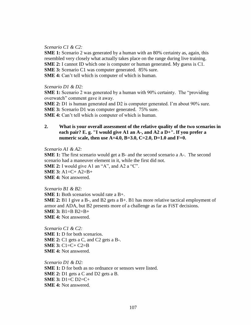
107
Scenario C1 & C2:
SME 1: Scenario 2 was generated by a human with an 80% certainty as, again, this
resembled very closely what actually takes place on the range during live training.
SME 2: I cannot ID which one is computer or human generated. My guess is C1.
SME 3: Scenario C1 was computer generated. 85% sure.
SME 4: Can’t tell which is computer of which is human.
Scenario D1 & D2:
SME 1: Scenario 2 was generated by a human with 90% certainty. The “providing
overwatch” comment gave it away.
SME 2: D1 is human generated and D2 is computer generated. I’m about 90% sure.
SME 3: Scenario D1 was computer generated. 75% sure.
SME 4: Can’t tell which is computer of which is human.
2. What is your overall assessment of the relative quality of the two scenarios in
each pair? E. g. "I would give A1 an A-, and A2 a D+". If you prefer a
numeric scale, then use A=4.0, B=3.0, C=2.0, D=1.0 and F=0.
Scenario A1 & A2:
SME 1: The first scenario would get a B- and the second scenario a A-. The second
scenario had a maneuver element in it, while the first did not.
SME 2: I would give A1 an “A”, and A2 a “C”.
SME 3: A1=C+ A2=B+
SME 4: Not answered.
Scenario B1 & B2:
SME 1: Both scenarios would rate a B+.
SME 2: B1 I give a B-, and B2 gets a B+. B1 has more relative tactical employment of
armor and ADA, but B2 presents more of a challenge as far as FiST decisions.
SME 3: B1=B B2=B+
SME 4: Not answered.
Scenario C1 & C2:
SME 1: D for both scenarios.
SME 2: C1 gets a C, and C2 gets a B-.
SME 3: C1=C+ C2=B
SME 4: Not answered.
Scenario D1 & D2:
SME 1: D for both as no ordnance or sensors were listed.
SME 2: D1 gets a C and D2 gets a B.
SME 3: D1=C D2=C+
SME 4: Not answered.

108
3. For each scenario, what are its strongest and weakest points? Were there any
obvious omissions that seemed to you to clearly indicate some weakness in
the process by which it was generated? What were those omissions and how
could the scenario be improved?
Scenario A1 & A2:
SME 1: The first scenario had no maneuver element position addressed. A specific T&R
event listed would be required to accurately assess the quality of the scenario, for
example TAC-OAS-2008. Aircraft sensors were not listed (Litening pod, ATFLIR, etc.).
SME 2: For scenario A1, the strong point is that it provides a good scenario for use of
fires in support of the maneuver element. The weak point is that it doesn’t necessarily
match the right ADA asset to a mechanized platoon. Usually a mechanized platoon will
have a ZSU 23-4, though MANPAD’s (SA-14) is possible as well.
For scenario A2, the strong point is it provides a thinking challenge in a way to attack
with air. The weak point is it is only 2 vehicles, both of with are easily destructible due to
proximity with artillery assets. Nothing really needed as far as excess coordination of
fires in the scenario.
SME 3: A1: Layout of friendly pos was atypical. Enemy forces were between FiST and
IDF assets. No mention of friendly forces other than FiST and IDF.
A2: More logical scenario than A1. Lead trace of company given.
For both scenarios, more details of air support would help. Is A/C targeting pod capable?
Loadout is unrealistic. Recommend mix of LGB, JDAM, and gun for fixed wing. For
example, F-18 with 2xGBU-12, 1XGBU-38, gun, and LPOD.
SME 4: Missing too much planning information to provide useful training scenarios.
There is a large amount of basic data missing from the depictions in both cases.
Scenario B1 & B2:
SME 1: Again the maneuver lead trace was omitted from one of the scenarios. The
aircraft and ordnance on station at the time would mean that the FAC could prosecute all
targets without having to use IDF. Aircraft Sensors were not listed.
SME 2: B1: Strength- Well employed enemy tactical situation. Armor up front for
infantry and ADA in back to pick off aircraft attempting to attack. Weakness- SA-13 is
not a very heavy threat for FW or even RW aircraft at the right distance, especially with
PGM’s.
B2: Strength- ADA presents more of a threat to aircraft, especially RW. Requires the
FiST to decide either to destroy the ZSU, or work around it through SEAD. All would
depend on commander’s guidance and actual combat scenario. Weakness: The spacing of
armor and the ADA threat is a little much, making use of SEAD too easy of an option, so
as not to waste too much time or firepower.
SME 3: Similar to scenario A.
B1: No mention of friendly forces other than FiST and IDF.
A2: Lead trace of company given.
SME 4: Missing too much planning information to provide useful training scenarios.
There is a large amount of basic data missing from the depictions in both cases.

109
Scenario C1 & C2:
SME 1: These scenarios lacked critical details that are required for making appropriate
decisions. No sensor capabilities were listed, nor was the type of ordnance listed. These
are required as they drive the tactics to be used.
SME 2: The only major difference is C2 has the strong point of having a realistic IP.
Otherwise both scenarios do not have much of a challenge in way, except in a basic
training scenario. With that in mind, I think it is an ok scenario, but more information on
ordnance and aircraft systems on board would be beneficial.
SME 3: Both scenarios need aircraft details; ordnance, pod capability.
SME 4: Missing too much planning information to provide useful training scenarios.
There is a large amount of basic data missing from the depictions in both cases
Scenario D1 & D2:
SME 1: Without knowing the ordnance to be employed, it is not possible to truly grade a
scenario as it is an incomplete scenario. The capabilities of the aircraft drive the scenario
more than the geographic location of things more often than not.
SME 2: D1: Strength- Close proximity fight, requiring more detailed integration with the
maneuver element. Weakness- all points seem relatively close, leaving aircraft little time
for maneuver into final attack cone, which would be constricting due to proximity of
friendly forces.
D2: Strength- allows for more FS options and aircraft tactics. Weakness: at 5 kilometers,
the target may be hard to make out and attack properly. Would have to rely mostly on
aircraft for BDA and adjustment of fires.
Overall weak point: Helicoptors do not like to fly solo. If the single helo in both scenarios
is FAC(A) capable, then it makes sense. Otherwise, he should have a wingman.
SME 3: Both scenarios need aircraft details; ordnance, pod capability.
SME 4: Missing too much planning information to provide useful training scenarios.
There is a large amount of basic data missing from the depictions in both cases

110
System Questions:
1. Please discuss your thoughts on the scenario generation model of baselines
and vignettes. In what ways does this model correspond with, or differ from,
the practice of professionals who generate scenarios? In what ways could this
model be improved?
SME 1: A specific T&R event should be listed. The event to be conducted will drive the
placement of things on the battlefield as well as the capabilities that I want the aircraft to
have (or not have) to force the FAC under instruction into doing what I want to see. For
example, if I want the FAC to use interrupted suppression on a ZSU-23-4, I will make
sure that the FW aircraft do not have any Laser-guided bombs. This is because if the
aircraft checked in with a GBU-12, it could just drop the bomb on the ZSU-23-4 from an
altitude sanctuary and he may not employ SEAD. It would be a correct tactical decision,
but it would not meet my training goal of having him employ SEAD with CAS fires.
SME 2: The scenarios are very similar to what we would come up with for our own
personnel to train with. Depending on their level of skill, we may also add ROE and have
them go through the dilemma of figuring that out as well. My best suggestion is to look
at some military personnel’s scenarios and copy/ alter them to fit into the different
scenarios you need.
SME 3: All scenarios are basic and accomplish basic requirements. Ordnance specifics
are the most lacking in all scenarios. The ordnance and sensor capability drive execution
more than any other aspect of the mission and must be realistic. Also, commander’s
intent is a key element not covered in these scenarios. Each scenario should have a
defined training goal. Once that goal is determined, ordnance and commander’s intent
can be tailored to meet training requirements.
SME 4: Since conflicts are confusing any of the situations presented can happen; that's
just life. The ground T&Rs don't possess the details you need to evaluate performance.
Unfortunately, those documents are the official source for performance standards.

111
2. Please discuss your thoughts on the vignette representation of sets of triggers
and adaptations. Does this representational system accurately and
completely capture the corresponding features that are needed for top
quality scenario generation? In what ways could our representational system
be improved?
SME 1: Again, the aircraft capabilities piece is the critical missing piece. More specifics
into what learning point the instructor wants to make—is it conducting CAS and SEAD
or is it setting up combined attacks (sequential/simultaneous)? This needs to be the
starting point from which the elements of the scenario flow.
SME 2: Symbols are good. Standard enough that most military personnel will understand
them.
SME 3: In addition to the above, geography must be considered in the development of
the scenarios. Location where personnel would or would not be located, terrain masking
for ground personnel and RW assets, etc. This is secondary to what is stated in question
1. Once training objectives are determined, enemy, threat and commanders intent
established, and aircraft ordnance, caps and ROE are defined, where units are placed on a
map are less important.
SME 4: As you can imagine this causes a great deal of anxiety in many organizations.
For instance, you need a base of fire for many tactical activities, yet (unless something
changed recently) the details how to execute or evaluate the base of fire don't exist in the
T&R manuals. Since training systems fundamentally offer the opportunity to "measure
something and provide feedback in a plausible environment" so to speak, we routinely
come up short when attempting to use the T&R as the primary source in many cases.
In this case we need to use TTECG's FiST Handbook for performance details on fire
planning. The T&Rs use to just say, "brief fire plan" or "build fire plan in accordance
with commander's guidance" or something like that. You can't produce a training device
focusing on fire plans with only that level of guidance available.
If the newer T&R manuals possess more of the details needed, that will be great.

112
LIST OF REFERENCES
[1] D. Lampton, private communication, 2007.
[2] R. T. Hayes et al., “Flight simulator training effectiveness: a meta-analysis,”
Military Psychology, vol. 4, pp. 63-74, 1992
[3] R. L. Oser et al., “Training team problem solving skills: an event-based
approach,” Computers in Human Behavior, vol. 15 (3-4), no. 31, pp. 441-462,
1999.
[4] T. de Jong and M. R. van Joolingen, “Scientific discovery learning with computer
simulations of conceptual domains,” Review of Educational Research, vol. 68, no.
2, pp. 179-201, 1998.
[5] J. Fowlkes et al., “Event-based approach to training (EBAT),” The International
Journal of Aviation Psychology, vol. 8, no. 3, pp. 209-221, 1998.
[6] G. Martin, et al., “Automatic scenario generation through procedural modeling for
scenario-based training,” in Proc. of the 53rd Annual Conf. of the Human Factors
and Ergonomics Society, Santa Monica, CA, 2009.
[7] J.A. Cannon-Bowers and E. Salas, “Team performance and training in complex
environments: recent findings from applied research,” Current Directions in
Psychological Science, vol. 7, no. 3, pp. 83-87, 1998.
[8] K. G. Ross et al., “Creating expertise: a framework to guide simulation-based
training,” in Proc. of Interservice/Industry Training, Simulation and Education
Conf., Orlando, FL, 2005.
[9] E. Salas et al., “The design and delivery of crew resource management training:
exploiting available resources,” Human Factors, vol. 42, no. 3, pp. 490-511,
2000.
[10] C. E. Zsambok and G. A. Klein, Naturalistic Decision Making. Mahwah, NJ:
Lawrence Erlbaum, 1997.
[11] S. B. Issenberg and R. J. Scalese, “Best evidence on high-fidelity simulation:
what clinical teachers need to know,” The Clinical Teacher, vol. 4, no. 2, pp. 73-
77, 2007.
[12] E. Grois et al., “Bayesian network models for generation of crisis management
training scenarios,” in Proc. of Innovative Applications of Artificial Intelligence
Conf., 1998, pp. 1113-1120.

113
[13] J. M. Beaubien and D. P. Baker, “The use of simulation for training teamwork
skills in health care: how low can you go?,” Quality and Safety in Health Care,
vol. 13, pp. i51-i56, 2004.
[14] H. Lum et al., “Complexity in collaboration: developing an understanding of
macrocognition in teams through examination of task complexity,” in Proc. of
52nd
Annu. Meeting of the Human Factors and Ergonomics Society, New York,
NY, 2008.
[15] R. E. Wood, “Task complexity: definition of the construct,” Organizational
Behavior and Human Decision Processes, vol. 37, pp. 60-82, 1986.
[16] D. J. Campbell, “Task complexity: a review and analysis,” Academy of
Management Review, vol. 13, pp. 40-52, 1988.
[17] Joint Staff, “Universal joint task list,” Joint Chiefs of Staff, Washington, DC, Rep.
CJCSM 3500.04D, 2005.
[18] Military Scenario Definition Language Product Development Group, “Standard
for: military scenario definition language,” Simulation Interoperability Standards
Organization, Orlando, FL, Rep. SISO-STD-007-2008, 2008.
[19] C. Bowers et al., “Rapidly reconfigurable event-set based line operational
evaluation scenarios,” Proc. of the Human Factors and Ergonomics Society, vol.
4, pp. 912-915, 1997.
[20] F. Jentsch et al., “Do three easy tasks make one difficult one: studying the
perceived difficulty of simulation scenarios,” in Proc. of the 10th Int. Symp. on
Aviation Psychology, Columbus, OH, 1999.
[21] F. Jentsch, et al., “Differences in situation assessment between experts and
prospective first officers,” in Proc. of the 9th Int. Symp. on Aviation Psychology,
Columbus, OH, 1997, pp. 1228-1232.
[22] R. J. Hall, “Explanation-based scenario generation for reactive system models,” in
Proc. of the 13th Conf. on Automated Software Engineering, Honolulu, HI, 1998.
[23] M. W. Pfefferman, “A Prototype Architecture for an Automated Scenario
Generation System for Combat Simulations,” Thesis, Air Force Institute of
Technology (Air University), 1993.
[24] KBSI (2008). FEAST: Framework for Enabling Adaptive Scenario Generation
for Training [Online]. Available: http://www.kbsi.com/

114
[25] N. Di Domenica et al., “Stochastic programming and scenario generation within a
simulation framework: an information systems perspective.” Decision Support
Systems, vol. 42, no. 4, pp. 2197-2219, 2007.
[26] D. Reynolds, “A framework for scenario generation,” Algo Research Quarterly,
vol. 4, no. 3, pp. 15-36. 2001.
[27] B. Laurel, “Toward the design of a computer-based interactive fantasy system,”
Ph.D. dissertation, Drama Department, Ohio State University, Columbus, OH,
1986.
[28] M. Mateas and A. Stern, “Façade: an experiment in building a fully-realized
interactive drama,” in Proc. Game Developers Conf., San Jose, CA, 2003.
[29] R. M. Young, “An overview of the Mimesis architecture: integrating intelligent
narrative control into an existing gaming environment,” in Working Notes of the
AAAI Spring Symp. On Artificial Intelligence and Interactive Entertainment,
2001.
[30] B. Magerko et al., “AI characters and directors for interactive computer games,”
in Proc. of the 16th National Innovative Applications of AI Conf., 2004.
[31] M. O. Riedl et al., “Dynamic experience management in virtual worlds for
entertainment, education, and training,” in International Transactions on Systems
Science and Applications, vol. 4, no. 1, pp. 23–42, 2008.
[32] R. E. Fikes and N. J. Nilsson, “STRIPS: a new approach to the application of
theorem proving to problem solving,” Artificial Intelligence, vol. 2, pp. 189-205,
1971.
[33] B. Medler and B. Magerko, “Scribe: a tool for authoring event driven interactive
narrative drama,” in Proc. of the 3rd Int. Conf. on Technologies for Interactive
Digital Storytelling and Entertainment, 2006.
[34] M. Ponder et al., “Immersive vr decision training: telling interactive stories
featuring advanced virtual human simulation technologies,” in Proc. of 14th
Eurographics Symp. On Virtual Environments: 9th Eurographics Workshop on
Virtual Environments, 2003, pp. 97–106.
[35] J. Fowlkes et al., “Contrasting cases: a strategy for advanced learning using
simulation-based training,” in Proc. of the 53rd Annual Conf. of the Human
Factors and Ergonomics Society, Santa Monica, CA, 2009.
115
[36] G. A. Martin et al., “What is a scenario? operationalizing training scenarios for
automatic generation,” in Proc. of the Applied Human Factors and Ergonomics
Conf., 2010.
[37] H. Tomizawa and A. Gonzalez, A, “Automated scenario generation system in a
simulation, “ in Proc. of Interservice/Industry Training, Simulation and Education
Conf., Orlando, FL, 2007.
[38] R. C. Hofer, and S. H. Smith, “Automated scenario generation environment,” in
Proc. of the Simulation Interoperability Workshop, Orlando, FL, 1998.
Available: www.sisostds.org
[39] U. S. Marine Corps, “Infantry training and readiness manual,” Department of the
Navy, Washington, DC, Rep. NAVMC DIR 3500.87, 2005.
[40] R. Dunne et al., “Scenario-based training: scenario complexity,” Proc. Annual
Conf. of the Human Factors and Ergonomics Society, 2010.
[41] D. S. Ebert et al., Texturing & Modeling: A Procedural Approach, 3rd
ed., San
Francisco, CA: Morgan Kauffmann, 2003.
[42] Minecraft (February 2012). “Minecraft” [Online]. Available: http://
http://www.minecraft.net/.
[43] B. B. Mandelbrot, Fractals: Form, Chance and Dimension, San Francisco, CA:
W. H. Freeman, 1977.
[44] Wolfram MathWorld (December 2007). “Koch Snowflake” [Online]. Available:
http://mathworld.wolfram.com/KochSnowflake.html.
[45] R. M. Crownover, Introduction to Fractals and Chaos, Boston, MA: Jones &
Bartlett, 1995.
[46] K. J. Hsu and A. J. Hsu, “Fractal Geometry of Music,” Proc. of the National
Academy of Sciences of the United States of America, vol. 87, pp. 938-941, 1990.
[47] D. L. Turcotte, “A fractal approach to probabilistic seismic hazard assessment,”
Tectonophysics, vol. 167, pp. 171-177, 1989.
[48] A. Lindenmayer, "Mathematical models for cellular interactions in development,
parts i and ii," Journal of Theoretical Biology, vol.18, pp.280-315, 1968.
[49] Wikipedia, Wikimedia Foundation (December 2007). “L-system” [Online].
Available: http://en.wikipedia.org/wiki/Lindenmayer_system

116
[50] Y. I. H. Parish and P. Müller, “Procedural modeling of cities,” in Computer
Graphics (SIGGRAPH 2001 Proceedings), 2001.
[51] P. Müller, et al., “Procedural modeling of buildings,” in ACM Transaction on
Graphics (SIGGRAPH 2006 Proceedings), 2006.
[52] G. Stiny, Pictorial and Formal Aspects of Shape and Shape Grammars, Basel,
Switzerland: Birkhauser Verlag, 1975.
[53] P. Wonka, et al., “Instant architecture,” in ACM Transactions on Graphics
(SIGGRAPH 2003), 2003.
[54] J. Marvie, et al., “The fl-system: a functional l-system for procedural geometric
modeling,” in The Visual Computer, vol.21, pp.329-339, 2005.
[55] G. A. Martin et al., “The use of functional l-systems for scenario generation in
serious games,” in Proc. of the Foundations of Digital Games (Workshop on
Procedural Content Generation in Games), Monterey, CA, 2010.
[56] G. A. Martin and C. E. Hughes, “A scenario generation framework for automating
instructional support in scenario-based training,” in Proc. of the Spring Simulation
Multiconference (Military Modeling and Simulation Symp.), Orlando, FL, 2010.
[57] R. Dunn, et al., “Scenario-based training: scenario complexity,” in Proc. of the
54th Annual Meeting of the Human Factors and Ergonomics Society (HFES), San
Francisco, CA, 2010.
[58] A. M. Turing, “Computing machinery and intelligence,” in Mind, vol. 59, pp.
433-460, 1950.
[59] N. Weber and N. Brewer, “Confidence-accuracy calibration in absolute and
relative face recognition judgments,” in Journal of Experimental Psychology, vol.
10 (3), pp. 156-172, 2004.
[60] N. Yelland and J. Masters, “Rethinking scaffolding in the information age,” in
Computers and Education, vol. 48, pp. 362-382, 2007.
[61] S. Greuter, “Undiscovered worlds – towards a framework for real-time procedural
world generation,” in Proc. of the 5th Intl. Digital Arts and Culture Conf.,
Melbourne, 2003.
[62] C. A. Pickover, “Generating extraterrestrial terrain,” in Computer Graphics and
Applications, vol. 15, pp. 18-21, 1995.
[63] J. Olsen, “Realtime procedural terrain generation,” University of Southern
Denmark, Tech. Rep #, 2004.

117
[64] R. M. Smelik, et al., “A survey of procedural methods for terrain modeling,” in
Proc. of the CASA Workshop on 3D Advanced Media in Gaming And
Simulation, Amsterdam, 2009.
[65] E. Hahn, et al., “Persistent realtime building interior generation,” in Proc. of the
ACM SIGGRAPH Symp. on Videogames, Boston, MA, 2006.
[66] J. Martin, “Procedural house generation: a method for dynamically generating
floor plans,” in Proc. of the Symp. on Interactive 3D Graphics and Games,
Redwood City, CA, 2006.