Automatic Satellite System Model 9702 Model 9702-LP · Page 2 The King-Dome Automatic Satellite...
20
11200 Hampshire Avenue South, Bloomington, MN 55438-2453 Phone: (800) 982-9920 Fax: (952) 922-8424 www.kingcontrols.com 1347 REV U Satellite Solutions for Mobile Markets ® Automatic Satellite System Model 9702 Model 9702-LP Installation and Operating Instructions
Transcript of Automatic Satellite System Model 9702 Model 9702-LP · Page 2 The King-Dome Automatic Satellite...

11200 Hampshire Avenue South, Bloomington, MN 55438-2453Phone: (800) 982-9920 Fax: (952) 922-8424
www.kingcontrols.com
1347 REV U
Satellite Solutions for Mobile Markets®
Automatic Satellite System
Model 9702Model 9702-LP
Installation and Operating Instructions


Page 1
IMPORTANT!The satellite TV market is expanding and changing. The information in this manual wasaccurate at the time of printing. If your King-Dome does not operate as outlined in thismanual please call King Controls at (800) 982-9920 or visit our website atwww.kingcontrols.com.
Please read this entire manual before beginning the installation.
Note: The following upgrade kit is available for this unit:
Upgrade Kit #9742: Adds built-in DVB for positive satellite identification and in-motiontracking capability.
For more information, call the King Controls Sales Department at (800)-982-9920.
TABLE OF CONTENTS
Section Contents Page
1. INTRODUCTION.....................................................................................2
2. DEFINITION OF TERMS ........................................................................3
3. INSTALLATION ..................................................................................4-11
4. OPERATION .........................................................................................12
5. MULTI-SWITCH ....................................................................................13
6. TROUBLESHOOTING ..........................................................................14
7. MAINTENANCE ....................................................................................15
8. LIMITED WARRANTY ..........................................................................16
DIRECTV® is a registered trademark of DIRECTV, Inc.Dish NetworkTM is an official trademark of Echostar Communications Corporation.Bell ExpressVu is an official trademark of Bell Canada.DVB® is a trademark of the DVB Digital Video Broadcast Project (1991-1996)

Page 2
The King-Dome Automatic Satellite System includes 2 main components (Fig. 1).
Dome (Antenna) Unit Located on the roof of the vehicle. The dish is covered by a protective dome that keeps operational components free fromthe elements.
Controller Located in the vehicle. Activates the search mode andprovides limited diagnostic functions using the status light.
SECTION 1 INTRODUCTION
Note: A TV, satellite receiver, and program subscription are also required for satellite TVviewing. (Purchased separately.)
Fig. 1
POWER
CHANGE SATELLITE
92° 101° 110° 119°
STATUS
ON / SEARCH OFF
ON/SEARCH
OFF SWITCHSATELLITE
STATUS
101
110
119

Page 3
AZIMUTH: Circular rotation around the vehicle.(like a clock face: front of vehicle is 12:00, rear is 6:00) (Fig. 2)
ELEVATION: Angle in degrees measured from the ground plane (Fig. 3).
SIGNAL STRENGTH: Intensity of electronic signal received from the satellite transmission.
SECTION 2 DEFINITION OF TERMS
Fig. 2
Fig. 3

KIT CONTENTS:
1. Unpack and identify all components (Fig. 4).
Page 4
SECTION 3 INSTALLATION
Fig. 4
TOOLS AND MATERIALS REQUIRED:
- drill and drill bit set- tape measure- 7/16” open end wrench (coax connections)- adhesive sealant (compatible with roof material)- appropriate fasteners to install all components and wiring- 5/32” allen wrench, channel lock or pliers (to remove shipping bolts)- wire cutter (to remove shipping tie strap)
King Dome Operating Instructions
1. Turn tv and satellite receiver ON.The tv screen should display “Searching for Satellite” or “Acquiring Satellite Signal.”
IMPORTANT DO NOT USE THE TV OR RECEIVER CONTROLS UNTIL YOU HAVE FOUND A SATELLITE.
2. On King-Dome controller, press and hold ON/SEARCHfor 3 FULL SECONDS.
3. Wait for status light to turn steady green.
4. Turn to a satellite channel that you normally watch. Is there a picture?
YES Press OFF and enjoy your programming.
NO Press ON/SEARCH until the Status Light beginsflashing and go back to step 3.DO NOT turn the system OFF until you lock onto the satellite with your programming.
5. Questions? Refer to owner’s manual
King-Dome
KIT CONTENTS

Page 5
IMPORTANT! The tie strap and spacer, and the bolts and washers must be removedfrom the bottom of the dome unit prior to installation. DO NOT REMOVETHE DOME COVER TO REMOVE THESE SHIPPING RESTRAINTS.
YOU MUST PLUG THE SHIPPING BOLT HOLES WITH THE SUPPLIEDPLUGS (ATTACHED TO TIE STRAP SHIPPING RESTRAINT).
2. Remove and discard the tie strap and spacer (KEEP RUBBER PLUGS), and the (2) boltsand (2) washers that pass through the bottom of the base (Fig. 5).
3. Insert provided plugs into holes that were occupied by the shipping bolts. Inserted plugsshould be flush with base (Fig. 5).
Fig. 5
IMPORTANT!Remove and discardTie Strap and Plastic
Spacer prior toinstallation.
KEEP RUBBERPLUGS.
IMPORTANT!Remove and discardBolts and Washersprior to installation.
IMPORTANT!After removing shipping bolts, firmlyinsert plugs into holes. Plugs should
be flush with base.

Page 6
DOME LOCATION
4. Select an area on the roof for the dome unit and the location where the wiring will enterthe vehicle through the roof to the satellite receiver, controller, and 12 volt power sourceinside, using the following criteria:
a) The shortest distance between the dome unit and the satellite receiver is mostdesirable.
b) The dome unit requires a 28 inch diameter mounting area.
c) The dome unit should be mounted on the centerline of the vehicle.
d) There must be no “line of sight” obstructions. Air conditioning units, other antennas,and storage areas that are too close to the dome unit may prevent the satellitesignal from reaching the dish (Fig. 6).
HEIGHT OFOBSTRUCTION
APPROXIMATE MINIMUM DISTANCE
TO DOME EDGE10” 8”11” 10”12” 12”
13” 14”
14” 16”
15” 18”
16” 20”
Fig.6
IMPORTANT! For installations on trucks with air shields, a bracket must be used formounting the dome unit. The dome unit MUST be mounted to the air ridecab: NEVER to any structure mounted directly to the frame.
See bracket instructions for proper installation (Fig. 7).

Page 7
s
5. Place dome unit on installation location chosen using the criteria discussed in theprevious section. Shipping restraints must be removed, plugs must be inserted in holes(Fig. 5, Page 5), and cable connections must be positioned facing rear of vehicle.
6. The dome unit must be positioned so that both feet on each side of the vehicle are equaldistances from the roof edge. This should be checked by measuring the distance fromeach foot to the roof edge. Confirm that these measurements are equal (Fig. 8).
IMPORTANT! Make sure shipping restraints are removed from bottom of dome unit andplugs are inserted in holes (Fig. 5, Page 5).
Cable connections must ALWAYS be positioned facing the rear of vehicle.
Example of truck installation using bracket.See bracket instructions for proper installation.
Fig. 8
Fig. 7
IMPORTANT! The dome unit MUST be mounted to the air ride cab: NEVER to any structuremounted directly to the frame.
DOME INSTALLATION
IMPORTANT! The dome should never be mounted so that it is tilted more thantwo degrees in any direction.
IMPORTANT!Cable connections must always faceREAR of vehicle.

Page 8
7. Mount the dome unit. Use the pre-drilled holes in the mounting feet as a guide to installthe fasteners into the roof. Use additional fasteners whenever necessary.
8. Test that the dome unit is secure by pulling upward from each foot location.
EXTERNAL WIRING
9. Plug external wire harness into wiring port on back of dome unit and tighten connectionuntil it clicks past the detent lock (Fig. 9).
10. Connect coax cable to coax port labeled MAIN on back of dome unit and tightenconnection. If using a second receiver, connect second coax cable to coax port labeledAUX and tighten connection. Do not over tighten coax connections (Fig. 9).
Note: The installer is responsible for determining the most appropriate fastener to secure thedome to the roof. Depending on the roof material, fasteners such as lag screws, wellnuts, sheet metal screws, toggle bolts and T anchors may be used, and should alwaysbe used in combination with a roof compatible sealant.
IMPORTANT! The installer is responsible for weatherproofing all holes with sealant.
Note: The King-Dome is wired for a dual LNB. There are two coaxial ports on the back of thedome unit. The one labeled “MAIN” MUST be connected to the main receiver in vehicle.The one labeled “AUX” can be used for an additional receiver.
IMPORTANT! Do not remove the rubber sleeves from the coax ports. The coax cableends will slide inside the sleeves as they are tightened.
Fig. 9
IMPORTANT!Coax connections will slide inside
rubber sleeves.
Coax connections should be snug.DO NOT OVER TIGHTEN!
IMPORTANT!The alignment tabs on the
wiring port and the externalwire harness plug must
match up when engagingplug onto port.
YOU MUST TIGHTEN THEPLUG UNTIL IT CLICKS
PAST THE DETENT LOCK.(A channel lock pliers may
be used to tighten theconnection.)

Page 9
11. Run wires from the back of the dome unit to the roof edge, then along edge to locationwhere wiring will be fed into the vehicle. (If installing an optional second receiver, runauxiliary coax to location where it will enter the vehicle.) Secure wiring to roof every 12-18 inches (Fig. 10).
12. Drill 3/4” hole through the roof and into the cabinet where receiver is stored. Feed wiringdown through hole. Seal opening with roof compatible sealant so that it is entirelywaterproof (inside and outside of the 3/4” hole). Repeat for optional second receiver (Fig. 10).
Fig. 10 TYPICAL ROOF INSTALLATION - OVERHEAD VIEW
IMPORTANT!Sealant must
be roofcompatible.
13. Remove blue protective sheet and red “position to rear” sticker from the dome unit.
Page 10
INTERNAL WIRING
14. Inside the vehicle, make the connections as shown in Fig. 11, keeping in mind thefollowing important points:
a) The connection between the dome unit and the receiver must be a directconnection with no devices in between. Any other devices should be downstreamfrom the receiver. Do not go through an “A-B” or any other switch, box, or booster.
b) Power connection must be a non-shared circuit. Excessive current draw on thecircuit will cause the unit to operate improperly. Power and ground connections mustbe made after the wires are connected to the dome unit.
Fig. 11
POWER
CHANGE SATELLITE
92° 101° 110° 119°
STATUS
ON / SEARCH OFF
ON/SEARCH
OFF SWITCHSATELLITE
STATUS
101
110
119

Page 11
ELEVATION PROGRAMMING - OPTIONAL
15. Find your location on the Elevation Maps below. The elevation line nearest to yourlocation is the elevation you will program.
Example: for Miami, Florida (DIRECTV elevation 52°): use 47° elevation linefor Miami, Florida (Dish Network elevation 38°): use 37° elevation line
STATUS LIGHT
Turns orange for 1 second, thenflashes red and/or green.
rapidly flashes red and greenrapidly flashes red and greenrapidly flashes red and greenrapidly flashes red and green
Turns momentarily orange, thenback to red or green
OFF.
SWITCH ACTION
Momentarily press ON/SEARCH and release.
Momentarily press ON/SEARCH and release a total of :
8 times: programs in 27 degree elevation12 times: programs in 37 degree elevation16 times: programs in 47 degree elevation20 times: programs in 55 degree elevation
Press ON/SEARCH and HOLD for 3 seconds.
Press OFF. (Must press OFF to completeprogramming.)
16. Use the Controller to perform the following commands:
Note: This unit is factory programmed to begin searching at elevation 37.8 degrees. To reduce initial satellite acquisition time, program the unit as follows: (Programming isoptional. If programming is not performed, the system will automatically adjust itselevation after satellite acquisition.)
101 DIRECTV Elevation Map 119 Dish Network Elevation Map

1. Turn on TV and Receiver. “Searching for Satellite” or similar will appear on TV screen.
2. On King-Dome controller, press and hold ON/SEARCH for 3 FULL SECONDS. Power light turns steady GREEN.
Page 12
a) flashes a variety of colorsfor about one minute
b) RED-flashing
c) GREEN-flashing (may start flashing RED again)
d) GREEN-steady
unit performs self-diagnostic
search in progress
potential satellite found
satellite found
IMPORTANT! There must be a clear “line of sight” to the southern sky. Mountains, buildings, trees,telephone poles, etc. can all block the satellite signal from reaching the dish.
The distance driven since last preforming a search may affect how long it takes for the King-Dome to find the satellite.
Satellite TV and receiver technology are constantly changing. If you experience difficulty go to www.kingcontrols.com or contact the King Controls Service Department at (800) 982-9920.
SECTION 4 OPERATION
STATUS LIGHT SYSTEM STATUSHand HeldController
3. Can you view your desired programming?
YES: Turn King-Dome off and enjoy.
NO: Press the ON/SEARCH button for onesecond to continue search. Repeat step until you are locked onto the correct satellite.
Note: Receiver may require 2 minutes todownload program information.
IMPORTANT! Do not turn off thecontroller until you havefound your desiredsatellite and programming.
Wall MountController

Page 13
SECTION 5 MULTI-SWITCH
FOR DISH 500 SUBSCRIBERS
After you have locked onto the 110 or 119 satellite using the operation procedure in Section 4,you can use either the Hand Held Controller or the Wall Mount Controller to move back and forthbetween the 110 and 119 satellites.
1. a) If you are locked onto the 110 satellite,press the hand held multi-switch TO THERIGHT, or the wall mount multi switch UP for one second.
The antenna will automatically move to the 119 satellite.
b) Press the hand held multi-switch TO THELEFT, or the wall mount multi switch DOWNfor one second to automatically return tothe 110 satellite.
2. a) If you are locked onto the 119 satellite,press the hand held multi switch TO THELEFT, or the wall mount multi-switch DOWN for one second.
The antenna will automatically move to the 110 satellite.
b) Press the hand held multi-switch TO THERIGHT, or the wall mount multi switch UPfor one second to automatically return tothe 119 satellite.

Page 14
SECTION 6 TROUBLESHOOTING
Diagnostic Keypad(Optional)
The Keypad is not included with this unit.It allows the installer to use advanced
diagnostics for installation andtroubleshooting. To order a Keypad
contact your local authorized King-Domedealer or call King Controls at
(800) 982-9920.
SYMPTOM POSSIBLE REASON COURSE OF ACTION
Unit does not find satellite.(STATUS light flashes redand/or green.)
Did not hold ON/SEARCH buttonfor 3 FULL SECONDS.
Hold ON/SEARCHbutton for 3 FULLSECONDS.
STATUS light flashesorange.
Before search: bad coaxconnection.
After unsuccessful search(approximately 25 minutes):obstruction in line of sight between dome and satellite.
Call King Controls.
Move vehicle to haveunobstructed view ofsouthern sky.
STATUS light does not stoprapidly flashing red andgreen.
Self check failed: potential motorproblem.
Call King Controls.
STATUS light does not turnon or is dim.
Bad power source (low voltage).
Bad power or controller cableconnection at dome.
Bad controller cable connection atcontroller.
Call King Controls.
Page 15
The King-Dome Satellite System has been designed to be maintenance and trouble free.
For optimum signal strength, keep the dome clean from dirt, bugs, and other debris. Periodicwashing of the dome with mild soap and water is recommended.
If you plan on storing your vehicle for long periods of time, it is recommended that the system beput through a search procedure on a quarterly basis to keep all moving parts in good workingorder.
If you have any comments or questions, please contact the King Controls Service Department at(800) 982-9920, or email King Controls at [email protected]
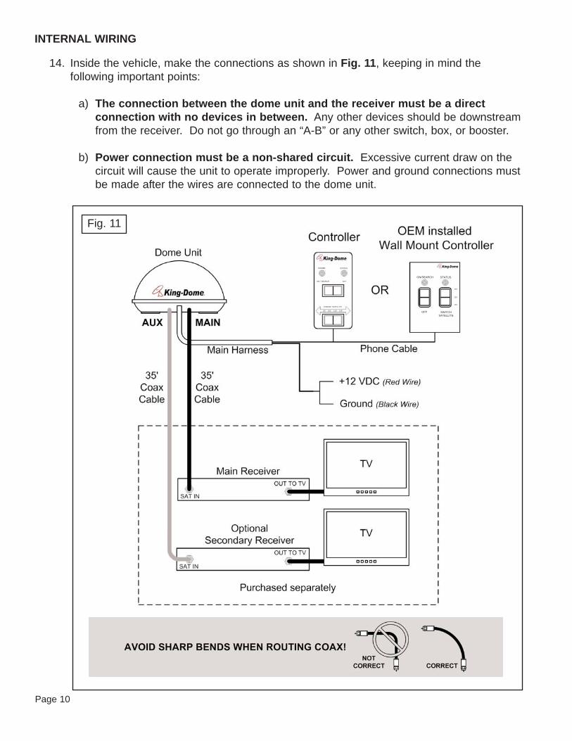
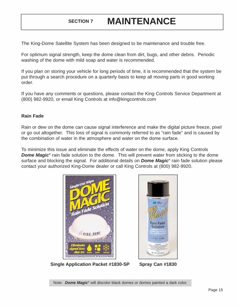
Rain Fade
Rain or dew on the dome can cause signal interference and make the digital picture freeze, pixelor go out altogether. This loss of signal is commonly referred to as “rain fade” and is caused bythe combination of water in the atmosphere and water on the dome surface.
To minimize this issue and eliminate the effects of water on the dome, apply King ControlsDome Magic® rain fade solution to the dome. This will prevent water from sticking to the domesurface and blocking the signal. For additional details on Dome Magic® rain fade solution pleasecontact your authorized King-Dome dealer or call King Controls at (800) 982-9920.
SECTION 7 MAINTENANCE
Single Application Packet #1830-SP Spray Can #1830
Note: Dome Magic® will discolor black domes or domes painted a dark color.

Page 16
Every King Controls Satellite System is thoroughly inspected and tested before leaving the factory. It is covered bya two year parts and one year labor limited warranty from the date of original purchase. This warranty does notcover installation and external wiring or refurbished units.
Should any trouble develop during the warranty period, contact King Controls. Only King Controls and certifieddealers are authorized to perform warranty evaluations and repairs.
If it is determined that the unit needs to be returned, return COMPLETE product, freight prepaid, to : King Controls, 11200 Hampshire Ave. S. Bloomington, MN 55438-2453. If inspection shows the trouble iscaused by defective workmanship or material, King Controls will repair (or at its option, replace) without charge.
This warranty does not apply where:
- The product has been abused, misused, improperly installed or improperly maintained.- Repairs have been made or attempted by others who are not certified by King Controls to do such repairs.- Repairs are required because of normal wear and tear.- Alterations have been made to the product.
In no event shall King Controls be liable for any indirect, incidental, or consequential damages from thesale or use of the product. This disclaimer applies both during and after the term of the warranty.
King Controls disclaims liability for any implied warranties, including implied warranties of“merchantability” and “fitness for a specific purpose,” after the one year term of this warranty.
This warranty gives you specific legal rights, and you may also have other rights, which vary from state to state.Some states do not allow the exclusion or limitation of incidental or consequential damages, so the above limitationor exclusion may not apply to you. Some states do not allow limitations on how long an implied warranty lasts, sothe above limitation may not apply to you.
SECTION 8 LIMITED WARRANTY


11200 Hampshire Avenue South, Bloomington, MN 55438-2453Phone: (800) 982-9920 Fax: (952) 922-8424
www.kingcontrols.com