
ppt of automatic room light controller and BI directional counter
description

1 “AUTOMATIC ROOM LIGHT CONTROLLER WITH BIDIRECTIONAL VISITOR COUNTER”
Certificate
Swami Sachchidanand Polytechnic College, (2nd Shift),
Visnagar.
TO WHOM SO EVER IT MAY CONCERN
This is to certify that PATEL PRATIK, PATEL BHAVIN, PATEL AKASHhaving Enrollment no. 106500309501, 106500309513, 106500309543,has completed part‐II UDP Project work having
He has undergone the process of shodh yatra , literature survey and problem definition. He is supposed to carry out the residue UDP Part‐II work on Same problem during sem‐VI for the final full filament of the UDP work which is prerequisite to complete Diploma Engineering.
Date:
Guide-
PRAKASH G. PATEL
Electrical Engg. Dept. Head Of Department
“AUTOMATIC ROOM LIGHT CONTROLLER WITH BIDIRECTIONAL VISITOR COUNTER”.
2 “AUTOMATIC ROOM LIGHT CONTROLLER WITH BIDIRECTIONAL VISITOR COUNTER”
“AUTOMATIC ROOM LIGHT CONTROLLER WITH BIDIRECTIONAL VISITOR COUNTER”.
PREPARED BY:‐
1.PATEL PRATIK J. (106500309501) 2.PATEL BHAVIN R. (106500309513) 3.PATEL AKASH B. (106500309543)

3 “AUTOMATIC ROOM LIGHT CONTROLLER WITH BIDIRECTIONAL VISITOR COUNTER”
::: AKNOWLEDGEMENT:::
The phenomenon remains same that no project ever can be executed
proficiently and efficiently without sharing the meticulous ideas, technical
expertise and innovative thought put forwarded by the technical and non
technical veterans.
It gives us pleasure in presenting this project report, undertaken by us as
per our Diploma Electrical 5th Semester Curriculum “Automatic Room Light
Controller With Bidirectional Visitor Counter “on having completed this project
Very first would like to thanks to the Prof.Mr. Prakash.G.PATEL -
H.O.D.EE DEPT. of SSPC VISHNAGAR. This project would not have been
possible without the efforts of the discrimination stood with us whenever any
difficulty came to our way and provided us grate support.
We are very personally thanks to our internal guide is Mr.
Prakash.G.PATEL. He has provided us a valuable guidance.
Finally, it’s a matter of fact that without the grace of the GOD & our
Parents, we wouldn’t have been able to complete the project.
With sincere regards.
4 “AUTOMATIC ROOM LIGHT CONTROLLER WITH BIDIRECTIONAL VISITOR COUNTER”
ABSTRACT
The fear of theft and burglary always annoys many people. When lock and keys become less safe, one can seek the help of electronic security systems. Such a portable security system is described here.
This electronic setup auto activated whenever the intruder enters to the unauthorized no entry area. It auto activate the landline number and redial the last dialed number from the conventional telephone. All we need is to do minor changes to activate this telephone as it works as to become auto dialer circuit.
Thus whenever the intruder enters to the area, it activates the sensor circuit
of either sound activation or infrared light beam obstruction circuit, the redial circuit become active and give a ring tone to the receiving end. It may be a mobile phone or any landline phone or even police control room.
5 “AUTOMATIC ROOM LIGHT CONTROLLER WITH BIDIRECTIONAL VISITOR COUNTER”
INDEX
CHAPTERCONTENTPAGE NO.
1. INTRODUCTION ………………………………………….. 6 1.1 Project Definition
1.2 Project Overview
2. BLOCKDIAGRAM AND ITS DESCRIPTION…………… 9
2.1Block Diagram Description:-
3. SCHEMATIC DIAGRAM & CIRCUIT DESCRIPTION……… 13
3.1. Transmission Circuit 3..2. R e c e i v e r C i r c u i t 4. LIST OF COMPONENTS………………………………….. 18
4.1. List of Components 5. DESCRIPTION OF COMPONENTS…………………………... 20 5.1 Description of Components 6. PROJECT FLOW CHART…………………………………… 27 7. PROJECT PROGRAM………………………………………. 30 8. FUTURE EXPANSION……………………………………. 38 9. APPLICATION, ADVANTAGES &DISADVANTAGES….. 40 10. REFERENCE BOOKS & WEBSITE……………………… 42

6 “AUTOMATIC ROOM LIGHT CONTROLLER WITH BIDIRECTIONAL VISITOR COUNTER”
CHAPTER: - 1
INTRODUCTION OF PROJECT
7 “AUTOMATIC ROOM LIGHT CONTROLLER WITH BIDIRECTIONAL VISITOR COUNTER”
Introduction Of Project :-
1.1 Project Definition:- Project title is “Automatic Room Light Controller With Bidirectional Visitor Counter”. The objective of this project is to make a controller based model to count number of persons visiting particular room and accordingly light up the room. Here we can use sensor and can know present number of persons. In today’s world, there is a continuous need for automatic appliances. With the increase in standard of living, there is a sense of urgency for developing circuits that would ease the complexity of life. Also if at all one wants to know the number of people present in room soaps not to have congestion, this circuit proves to be helpful. This project "automatic room light controller with visitor counter using microcontroller" is a reliable circuit that takes over the task of persons/visitor in the room very accurately. When somebody enters into the room will be switched ON and when any one. The light in room will be only switched OFF until all the persons in the room go out. The total number of person inside the room also displayed on the seven segment displays. The microcontroller does the above job. it receives the signals from the sencers, and this signal is operated under the control of software which is stored in rom. Micron roller AT89S52 continuously monitor the infrared receivers, when any object pass through the IR rays falling on the receivers are obstructed this obstruction is sensed by the microcontroller.
1.2Project Overview:-
This Project ―Automatic Room Light Controller with Visitor Counter
using Microcontroller is a reliable circuit that takes over the task of controlling the room lights as well us counting number of persons/ visitors in the room very accurately. When somebody enters into the room then the counter is incremented by one and the light in the room will be switched ON and when any one leaves the room then the counter is decremented by one. The light will be only switched OFF until all the persons in the room go out. The total number of persons inside the room is also displayed on the seven segment displays.

8 “AUTOMATIC ROOM LIGHT CONTROLLER WITH BIDIRECTIONAL VISITOR COUNTER”
The microcontroller does the above job. It receives the signals from the sensors, and this signal is operated under the control of software which is stored in ROM. MicrocontrollerAT89S52 continuously monitor the Infrared Receivers, When any object pass through the IR Receiver's then the IR Rays falling on the receiver are obstructed , this obstruction is sensed by the Microcontroller.
9 “AUTOMATIC ROOM LIGHT CONTROLLER WITH BIDIRECTIONAL VISITOR COUNTER”
CHAPTER :- 2
BLOCKDIAGRAM AND ITS DESCRIPTION
10 “AUTOMATIC ROOM LIGHT CONTROLLER WITH BIDIRECTIONAL VISITOR COUNTER”
2.1 Blockdiagram:-

11 “AUTOMATIC ROOM LIGHT CONTROLLER WITH BIDIRECTIONAL VISITOR COUNTER”
2.2Block Diagram Description:-
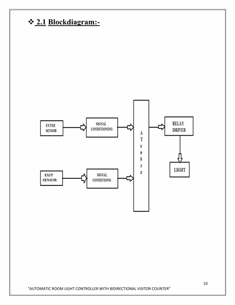
The basic block diagram of the bidirectional visitor counter with automatic light controller is shown in the above figure. Mainly this block diagram consists of the following essential blocks.
1. Power Supply 2. Entry and Exit sensor circuit 3. AT 89S52 micro-controller 4. Relay driver circuit
1. Power Supply:-
Here we used +12V and +5V dc power supply. The main function of this block is to provide the required amount of voltage to essential circuits. +12voltage is given. +12V is given to relay driver. To get the +5V dc power supply we have used here IC 7805, which provides the +5V dc regulated power supply.
2. Enter and Exit Circuits:-
This is one of the main parts of our project. The main intention of this block is to sense the person. For sensing the person and light we are using the light dependent register (LDR). By using this sensor and its related circuit diagram we can count the persons.
3. 89S52 Microcontroller:-
It is a low-power, high performance CMOS 8-bit microcontroller with8KB of Flash Programmable and Erasable Read Only Memory (PEROM). THE device is manufactured using Atmel’s high-density nonvolatile memory technology and is compatible with the MCS-51TMinstruction set and pin out. Theon-chip Flash allows the program memory to be reprogrammed in-system or by a conventional nonvolatile memory programmer. By combining a versatile 8-bitCPU with Flash on a monolithic hip, the Atmel AT89S52 is a powerful.

12 “AUTOMATIC ROOM LIGHT CONTROLLER WITH BIDIRECTIONAL VISITOR COUNTER”
4. Relay Driver Circuit:- This block has the potential to drive the various controlled devices. In this block mainly we are using the transistor and the relays. One relay driver circuit we are using to control the light. Output signal from AT89S52 is given to the base of the transistor, which we are further energizing the particular relay. Because of this appropriate device is selected and it do its allotted function.
13 “AUTOMATIC ROOM LIGHT CONTROLLER WITH BIDIRECTIONAL VISITOR COUNTER”
CHAPTER :- 3 SCHEMATIC DIAGRAM &CIRCUIT DESCRIPTION
14 “AUTOMATIC ROOM LIGHT CONTROLLER WITH BIDIRECTIONAL VISITOR COUNTER”
CIRCUIT DESCRIPTION;-
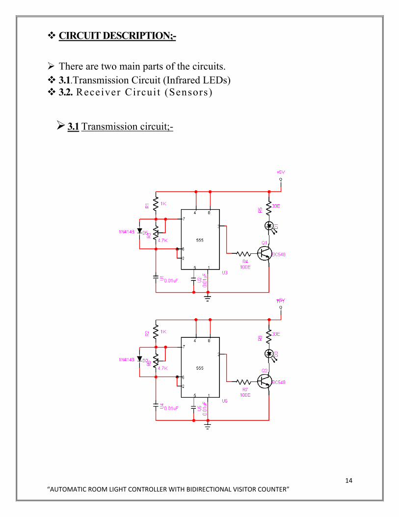
There are two main parts of the circuits. 3.1.Transmission Circuit (Infrared LEDs) 3.2. Receiver Circui t (Sensors)
3.1 Transmission circuit;-
15 “AUTOMATIC ROOM LIGHT CONTROLLER WITH BIDIRECTIONAL VISITOR COUNTER”
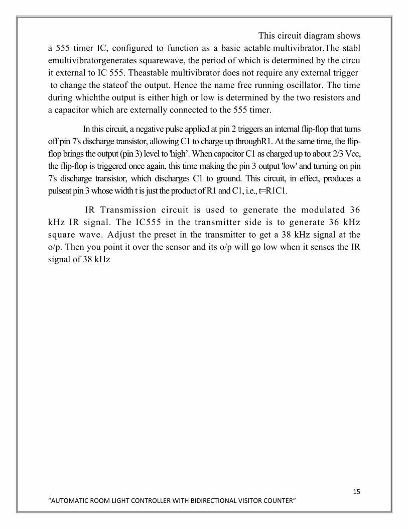
This circuit diagram shows a 555 timer IC, configured to function as a basic actable multivibrator.The stabl emultivibratorgenerates squarewave, the period of which is determined by the circuit external to IC 555. Theastable multivibrator does not require any external trigger to change the stateof the output. Hence the name free running oscillator. The time during whichthe output is either high or low is determined by the two resistors and a capacitor which are externally connected to the 555 timer.
In this circuit, a negative pulse applied at pin 2 triggers an internal flip-flop that turns off pin 7's discharge transistor, allowing C1 to charge up throughR1. At the same time, the flip-flop brings the output (pin 3) level to 'high’. When capacitor C1 as charged up to about 2/3 Vcc, the flip-flop is triggered once again, this time making the pin 3 output 'low' and turning on pin 7's discharge transistor, which discharges C1 to ground. This circuit, in effect, produces a pulseat pin 3 whose width t is just the product of R1 and C1, i.e., t=R1C1.
IR Transmission circuit is used to generate the modulated 36 kHz IR signal. The IC555 in the transmitter side is to generate 36 kHz square wave. Adjust the preset in the transmitter to get a 38 kHz signal at the o/p. Then you point it over the sensor and its o/p will go low when it senses the IR signal of 38 kHz
16 “AUTOMATIC ROOM LIGHT CONTROLLER WITH BIDIRECTIONAL VISITOR COUNTER”
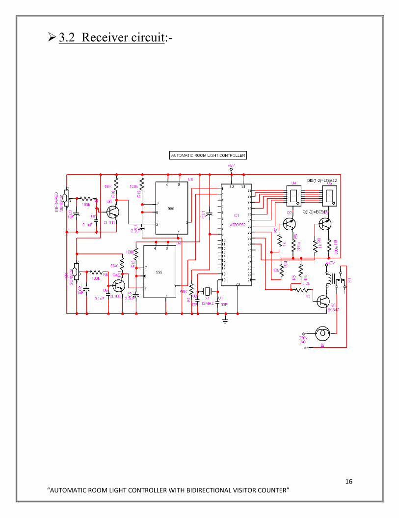
3.2 Receiver circuit:-

17 “AUTOMATIC ROOM LIGHT CONTROLLER WITH BIDIRECTIONAL VISITOR COUNTER”
The IR transmitter will emit modulated 38 kHz IR signal and at the receiver we use TSOP1738 ( In f rared Sensor ) . The outpu t goes h igh when there i s an in te r rup t ion and i t r e tu rn back to low af te r the t ime per iod de te rmined by the capacitor and resistor in the circuit i.e. around 1 second. CL100 is to trigger theIC555 which is configured as monostable multivibrator. Input is given to the Port 1of the microcontroller. Port 0 is used for the 7-Segment display purpose. Port 2 is used for the Relay Turn On and Turn off Purpose.LTS 542 (Common Anode) is used for 7-Segment display and that time Relay will get voltage and triggered, so light will get voltage and it will turn on and when counter will be 00 and at that time Relay will be turned off. Reset button will reset the microcontroller.
18 “AUTOMATIC ROOM LIGHT CONTROLLER WITH BIDIRECTIONAL VISITOR COUNTER”
CHAPTER: - 4
LIST OF COMPONENTS
19 “AUTOMATIC ROOM LIGHT CONTROLLER WITH BIDIRECTIONAL VISITOR COUNTER”
LIST OF COMPONENTS
1. Microcontroller – AT89S52 2. IC – 7805 3. Sensor – TSOP 1738 (Infrared Sensor) 4. Transformer – 12-0-12, 500 mA 5. Preset – 4.7K 6. Disc capacitor – 104,33pF 7. Reset button switch 8. Rectifier diode – IN4148 9. 9.Transistor – BC 547, 2N2222 10. 7-Segment Display
20 “AUTOMATIC ROOM LIGHT CONTROLLER WITH BIDIRECTIONAL VISITOR COUNTER”
CHAPTER: - 5
DESCRIPTION OF COMPONENTS
21 “AUTOMATIC ROOM LIGHT CONTROLLER WITH BIDIRECTIONAL VISITOR COUNTER”
5.1 Description of Components;-
1.Microcontroller AT89S52:- The AT89S52 is a low-power, high-performance CMOS 8-bit microcontroller with 8K bytes of in-system programmable Flash memory. The device is manufactured using Atmel’s high-density nonvolatile memory technology and is compatible with the Industry-standard 80C51 instruction set and pin out. The on-chip Flash allows the program memory to be reprogrammed in-system or by a conventional nonvolatile memory pro- grammar. By combining a versatile 8-bit CPU with in-system programmable Flash on a monolithic chip, the Atmel AT89S52 is a powerful microcontroller which provides a highly-flexible and cost-effective solution to many embedded control applications.
• FEATURES:-
1. 8 KB Reprogrammable flash. 2. 32 Programmable I/O lines. 3. 16 bit Timer/Counter—3. 4. 8 Interrupt sources. 5. Power range: 4V – 5.5V 6. Endurance : 1000 Writes / Erase cycles 7. Fully static operation: 0 Hz to 33 MHz 8. Three level program memory lock 9. Power off flag 10. Full duplex UART serial channel 11. Low power idle and power down modes 12. Interrupt recovery from power down modes 13. 256 KB internal RAM 14. Dual data pointer
22 “AUTOMATIC ROOM LIGHT CONTROLLER WITH BIDIRECTIONAL VISITOR COUNTER”
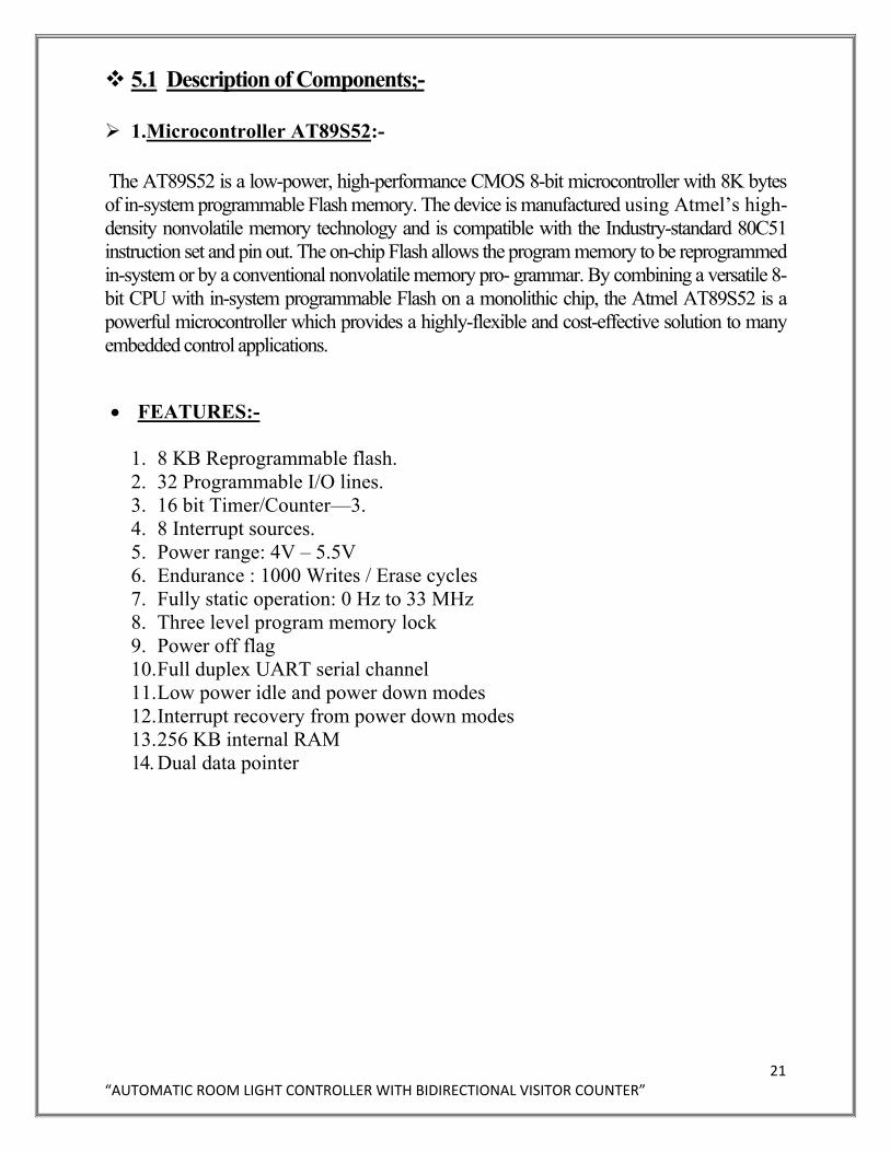
2.TSOP1738 (INFRARED SENSOR)
• Description:- The TSOP17.. – Series are miniaturized receivers for infrared remote control systems. PIN diode and preamplifier are assembled on lead frame, the epoxy package is designed as IR filter. The demodulated output signal can directly be decoded by a microprocessor. TSOP17... is the standard IR remote control receiver series, supporting all major transmission codes. • Features:-
1. Photo detector and preamplifier in one package 2. Internal filter for PCM frequency 3. Improved shielding against electrical field disturbance 4. TTL and CMOS compatibility 5. Output active low 6. Low power consumption 7. High immunity against ambient light 8. Continuous data transmission possible (up to 2400 bps)
23 “AUTOMATIC ROOM LIGHT CONTROLLER WITH BIDIRECTIONAL VISITOR COUNTER”
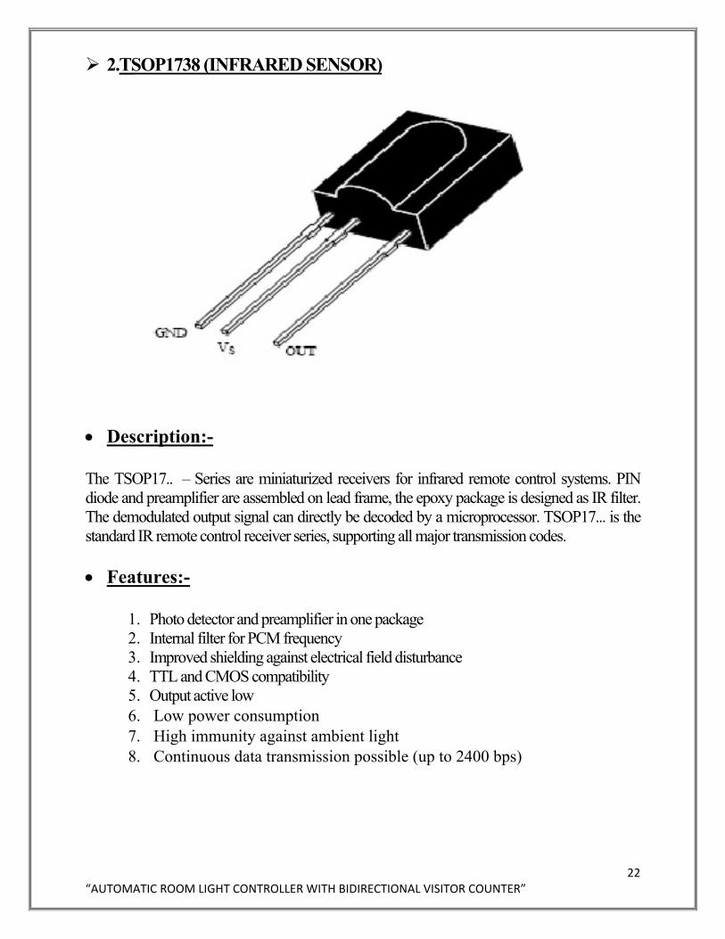
3. 555 (TIMER IC):-
- • Description:- - The LM555 is a highly stable device for generating accurate time delays or oscillation. Additional terminals are provided for triggering or resetting if desired. In the time delay mode of operation, the time is precisely controlled by one external resistor and capacitor. For actable operation as an oscillator, the free running frequency and duty cycle are accurately controlled with two external resistors and one capacitor. The circuit may be triggered and reset on falling waveforms, and the output circuit can source or sink up to 200mA or drive TTL circuits
• Features:
1. Direct replacement for SE555/NE555 2. Timing from microseconds through hours 3. Operates in both as table and monostable modes 4. Adjustable duty cycle 5. Output can source or sink 200 mAOutput and supply TTL compatible
24 “AUTOMATIC ROOM LIGHT CONTROLLER WITH BIDIRECTIONAL VISITOR COUNTER”
6. Temperature stability better than 0.005% per °C 7. Normally on and normally off output 8. Available in 8-pin MSOP package
• Applications:-
1. Precision timing 2. Pulse generation 3. Sequential timing
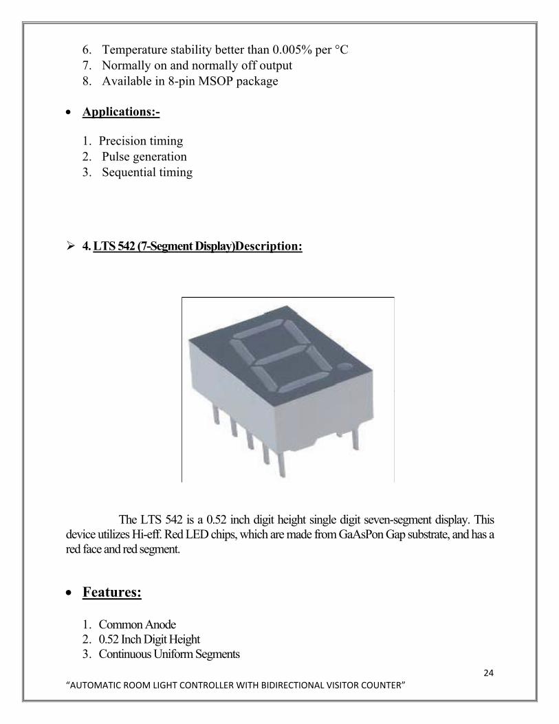
4. LTS 542 (7-Segment Display)Description:
The LTS 542 is a 0.52 inch digit height single digit seven-segment display. This device utilizes Hi-eff. Red LED chips, which are made from GaAsPon Gap substrate, and has a red face and red segment.
• Features:
1. Common Anode 2. 0.52 Inch Digit Height 3. Continuous Uniform Segments
25 “AUTOMATIC ROOM LIGHT CONTROLLER WITH BIDIRECTIONAL VISITOR COUNTER”
4. Low power Requirement 5. Excellent Characters Appearance
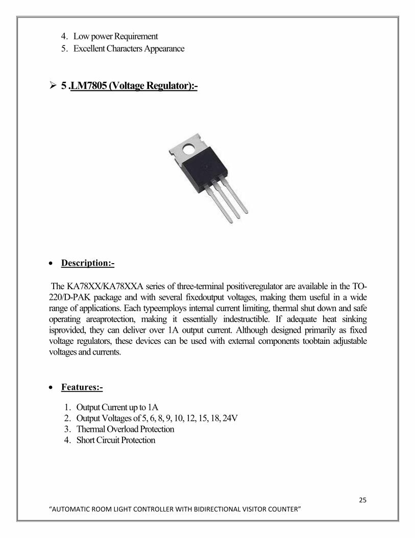
5 .LM7805 (Voltage Regulator):-
• Description:- The KA78XX/KA78XXA series of three-terminal positiveregulator are available in the TO-220/D-PAK package and with several fixedoutput voltages, making them useful in a wide range of applications. Each typeemploys internal current limiting, thermal shut down and safe operating areaprotection, making it essentially indestructible. If adequate heat sinking isprovided, they can deliver over 1A output current. Although designed primarily as fixed voltage regulators, these devices can be used with external components toobtain adjustable voltages and currents. • Features:-
1. Output Current up to 1A 2. Output Voltages of 5, 6, 8, 9, 10, 12, 15, 18, 24V 3. Thermal Overload Protection 4. Short Circuit Protection
26 “AUTOMATIC ROOM LIGHT CONTROLLER WITH BIDIRECTIONAL VISITOR COUNTER”
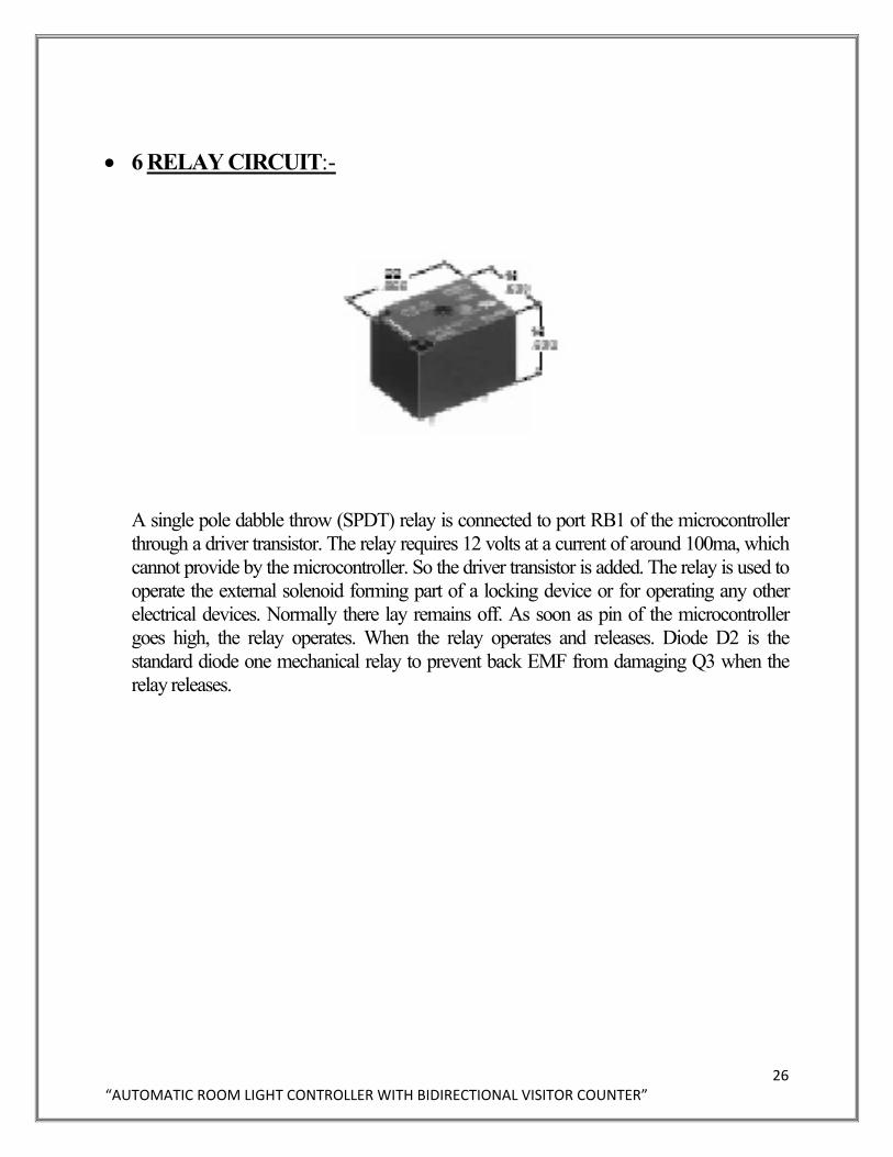
• 6 RELAY CIRCUIT:-
A single pole dabble throw (SPDT) relay is connected to port RB1 of the microcontroller through a driver transistor. The relay requires 12 volts at a current of around 100ma, which cannot provide by the microcontroller. So the driver transistor is added. The relay is used to operate the external solenoid forming part of a locking device or for operating any other electrical devices. Normally there lay remains off. As soon as pin of the microcontroller goes high, the relay operates. When the relay operates and releases. Diode D2 is the standard diode one mechanical relay to prevent back EMF from damaging Q3 when the relay releases.

27 “AUTOMATIC ROOM LIGHT CONTROLLER WITH BIDIRECTIONAL VISITOR COUNTER”
CHAPTER: - 6
PROJECT FLOW CHART

28 “AUTOMATIC ROOM LIGHT CONTROLLER WITH BIDIRECTIONAL VISITOR COUNTER”
FLOW CHART :-

29 “AUTOMATIC ROOM LIGHT CONTROLLER WITH BIDIRECTIONAL VISITOR COUNTER”
If the sensor 1 is interrupted first then the microcontroller will look for
the sensor 2, and if it is interrupted then the microcontroller will increment the count and switch on the relay, if it is first time interrupted. If the sensor 2 is interrupted first then the microcontroller will look for
the sensor 1, and if it is interrupted then the microcontroller will decrement the count. When the last person leaves the room then counter goes to 0 and that
time the relay will turn off, and light will be turned off.

30 “AUTOMATIC ROOM LIGHT CONTROLLER WITH BIDIRECTIONAL VISITOR COUNTER”
CHAPTER: - 7 PROJECT PROGRAM
31 “AUTOMATIC ROOM LIGHT CONTROLLER WITH BIDIRECTIONAL VISITOR COUNTER”
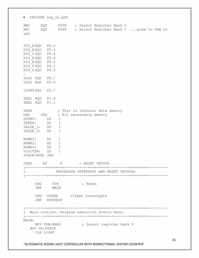
• INCLUDE reg_51.pdf RB0 EQU 000H ; Select Register Bank 0 RB1 EQU 008H ; Select Register Bank 1 ...poke to PSW to use DIS_A EQU P0.2 DIS_B EQU P0.3 DIS_C EQU P0.4 DIS_D EQU P0.6 DIS_E EQU P0.5 DIS_F EQU P0.1 DIS_G EQU P0.0 - DIS1 EQU P0.7 DIS2 EQU P2.6 LIGHT EQU P2.7 SEN1 EQU P1.0 SEN2 EQU P1.1 DSEG ; This is internal data memory ORG 20H ; Bit adressable memory COUNT: DS 1 SPEED: DS 1 VALUE_1: DS 1 VALUE_2: DS 1 NUMB1: DS 1 NUMB2: DS 1 NUMB3: DS 1 VISITOR: DS 1 STACK DATA 3FH CSEG AT 0 ; RESET VECTOR ;---------==========----------==========---------=========--------- ; PROCESSOR INTERRUPT AND RESET VECTORS ;---------==========----------==========---------=========--------- ORG 00H ; Reset JMP MAIN ORG 000BH ;Timer Interrupt0 JMP REFRESH ;---------==========----------==========---------=========--------- ; Main routine. Program execution starts here. ;---------==========----------==========---------=========--------- MAIN: MOV PSW,#RB0 ; Select register bank 0 MOV SP,STACK CLR LIGHT
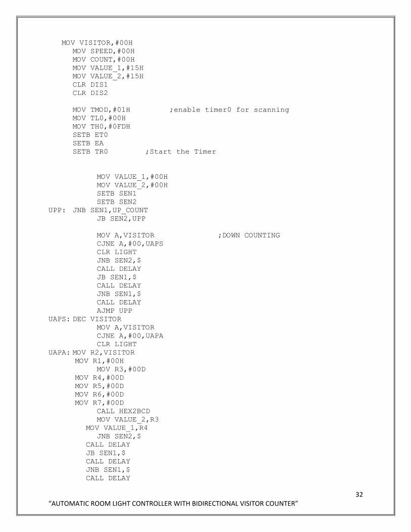
32 “AUTOMATIC ROOM LIGHT CONTROLLER WITH BIDIRECTIONAL VISITOR COUNTER”
MOV VISITOR,#00H MOV SPEED,#00H MOV COUNT,#00H MOV VALUE_1,#15H MOV VALUE_2,#15H CLR DIS1 CLR DIS2 MOV TMOD,#01H ;enable timer0 for scanning MOV TL0,#00H MOV TH0,#0FDH SETB ET0 SETB EA SETB TR0 ;Start the Timer MOV VALUE_1,#00H MOV VALUE_2,#00H SETB SEN1 SETB SEN2 UPP: JNB SEN1,UP_COUNT JB SEN2,UPP MOV A,VISITOR ;DOWN COUNTING CJNE A,#00,UAPS CLR LIGHT JNB SEN2,$ CALL DELAY JB SEN1,$ CALL DELAY JNB SEN1,$ CALL DELAY AJMP UPP UAPS: DEC VISITOR MOV A,VISITOR CJNE A,#00,UAPA CLR LIGHT UAPA: MOV R2,VISITOR MOV R1,#00H MOV R3,#00D MOV R4,#00D MOV R5,#00D MOV R6,#00D MOV R7,#00D CALL HEX2BCD MOV VALUE_2,R3 MOV VALUE_1,R4 JNB SEN2,$ CALL DELAY JB SEN1,$ CALL DELAY JNB SEN1,$ CALL DELAY
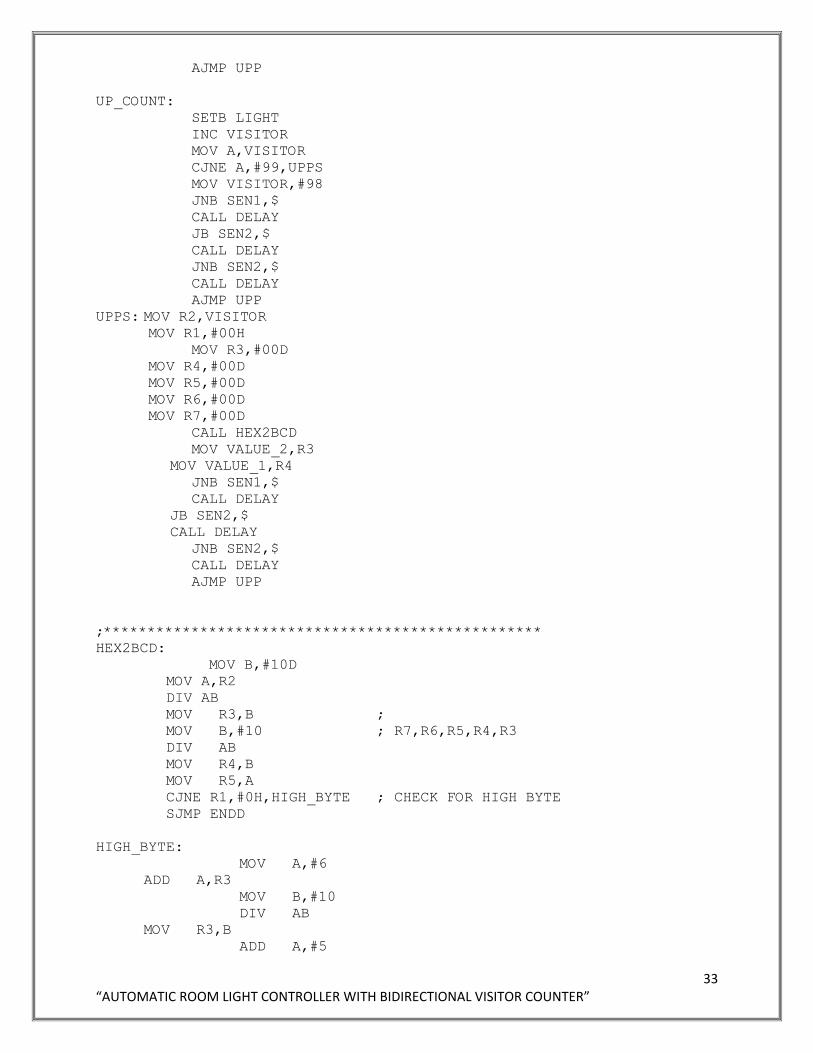
33 “AUTOMATIC ROOM LIGHT CONTROLLER WITH BIDIRECTIONAL VISITOR COUNTER”
AJMP UPP UP_COUNT: SETB LIGHT INC VISITOR MOV A,VISITOR CJNE A,#99,UPPS MOV VISITOR,#98 JNB SEN1,$ CALL DELAY JB SEN2,$ CALL DELAY JNB SEN2,$ CALL DELAY AJMP UPP UPPS: MOV R2,VISITOR MOV R1,#00H MOV R3,#00D MOV R4,#00D MOV R5,#00D MOV R6,#00D MOV R7,#00D CALL HEX2BCD MOV VALUE_2,R3 MOV VALUE_1,R4 JNB SEN1,$ CALL DELAY JB SEN2,$ CALL DELAY JNB SEN2,$ CALL DELAY AJMP UPP ;************************************************** HEX2BCD: MOV B,#10D MOV A,R2 DIV AB MOV R3,B ; MOV B,#10 ; R7,R6,R5,R4,R3 DIV AB MOV R4,B MOV R5,A CJNE R1,#0H,HIGH_BYTE ; CHECK FOR HIGH BYTE SJMP ENDD HIGH_BYTE: MOV A,#6 ADD A,R3 MOV B,#10 DIV AB MOV R3,B ADD A,#5
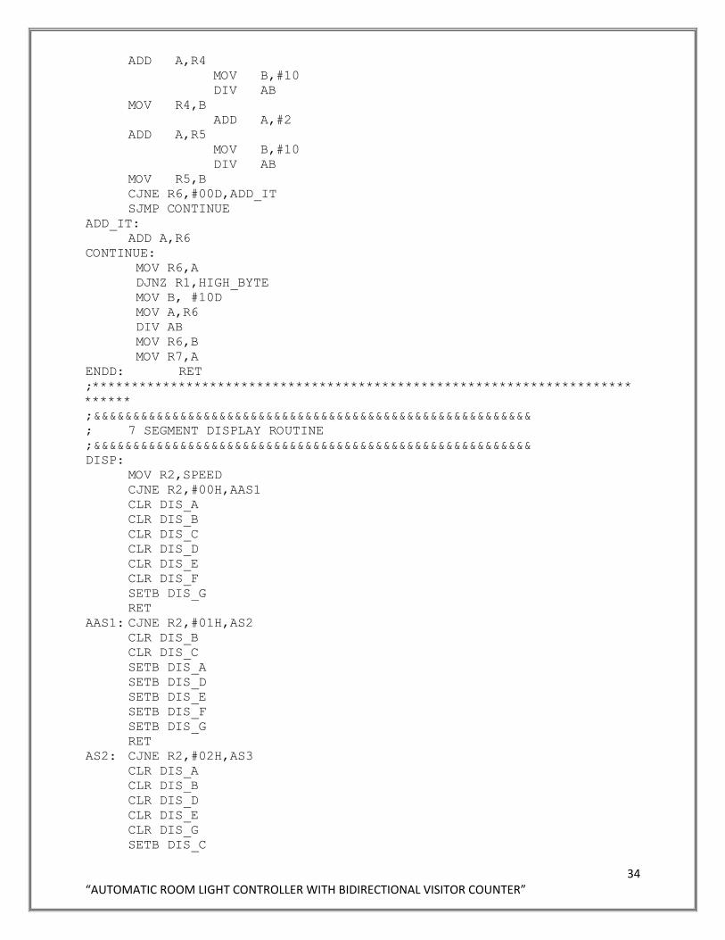
34 “AUTOMATIC ROOM LIGHT CONTROLLER WITH BIDIRECTIONAL VISITOR COUNTER”
ADD A,R4 MOV B,#10 DIV AB MOV R4,B ADD A,#2 ADD A,R5 MOV B,#10 DIV AB MOV R5,B CJNE R6,#00D,ADD_IT SJMP CONTINUE ADD_IT: ADD A,R6 CONTINUE: MOV R6,A DJNZ R1,HIGH_BYTE MOV B, #10D MOV A,R6 DIV AB MOV R6,B MOV R7,A ENDD: RET ;*************************************************************************** ;&&&&&&&&&&&&&&&&&&&&&&&&&&&&&&&&&&&&&&&&&&&&&&&&&&&&&&&& ; 7 SEGMENT DISPLAY ROUTINE ;&&&&&&&&&&&&&&&&&&&&&&&&&&&&&&&&&&&&&&&&&&&&&&&&&&&&&&&& DISP: MOV R2,SPEED CJNE R2,#00H,AAS1 CLR DIS_A CLR DIS_B CLR DIS_C CLR DIS_D CLR DIS_E CLR DIS_F SETB DIS_G RET AAS1: CJNE R2,#01H,AS2 CLR DIS_B CLR DIS_C SETB DIS_A SETB DIS_D SETB DIS_E SETB DIS_F SETB DIS_G RET AS2: CJNE R2,#02H,AS3 CLR DIS_A CLR DIS_B CLR DIS_D CLR DIS_E CLR DIS_G SETB DIS_C
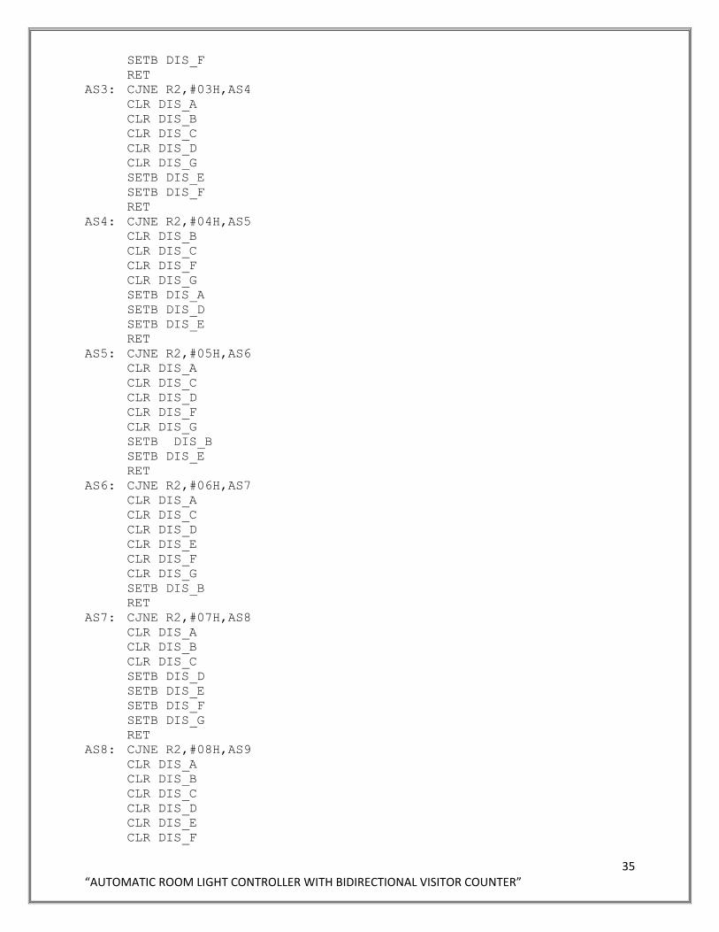
35 “AUTOMATIC ROOM LIGHT CONTROLLER WITH BIDIRECTIONAL VISITOR COUNTER”
SETB DIS_F RET AS3: CJNE R2,#03H,AS4 CLR DIS_A CLR DIS_B CLR DIS_C CLR DIS_D CLR DIS_G SETB DIS_E SETB DIS_F RET AS4: CJNE R2,#04H,AS5 CLR DIS_B CLR DIS_C CLR DIS_F CLR DIS_G SETB DIS_A SETB DIS_D SETB DIS_E RET AS5: CJNE R2,#05H,AS6 CLR DIS_A CLR DIS_C CLR DIS_D CLR DIS_F CLR DIS_G SETB DIS_B SETB DIS_E RET AS6: CJNE R2,#06H,AS7 CLR DIS_A CLR DIS_C CLR DIS_D CLR DIS_E CLR DIS_F CLR DIS_G SETB DIS_B RET AS7: CJNE R2,#07H,AS8 CLR DIS_A CLR DIS_B CLR DIS_C SETB DIS_D SETB DIS_E SETB DIS_F SETB DIS_G RET AS8: CJNE R2,#08H,AS9 CLR DIS_A CLR DIS_B CLR DIS_C CLR DIS_D CLR DIS_E CLR DIS_F
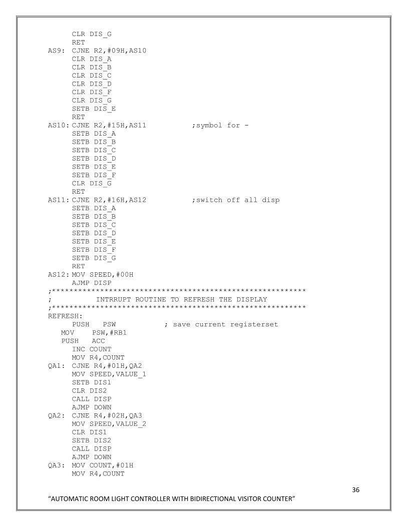
36 “AUTOMATIC ROOM LIGHT CONTROLLER WITH BIDIRECTIONAL VISITOR COUNTER”
CLR DIS_G RET AS9: CJNE R2,#09H,AS10 CLR DIS_A CLR DIS_B CLR DIS_C CLR DIS_D CLR DIS_F CLR DIS_G SETB DIS_E RET AS10: CJNE R2,#15H,AS11 ;symbol for - SETB DIS_A SETB DIS_B SETB DIS_C SETB DIS_D SETB DIS_E SETB DIS_F CLR DIS_G RET AS11: CJNE R2,#16H,AS12 ;switch off all disp SETB DIS_A SETB DIS_B SETB DIS_C SETB DIS_D SETB DIS_E SETB DIS_F SETB DIS_G RET AS12: MOV SPEED,#00H AJMP DISP ;********************************************************** ; INTRRUPT ROUTINE TO REFRESH THE DISPLAY ;********************************************************** REFRESH: PUSH PSW ; save current registerset MOV PSW,#RB1 PUSH ACC INC COUNT MOV R4,COUNT QA1: CJNE R4,#01H,QA2 MOV SPEED,VALUE_1 SETB DIS1 CLR DIS2 CALL DISP AJMP DOWN QA2: CJNE R4,#02H,QA3 MOV SPEED,VALUE_2 CLR DIS1 SETB DIS2 CALL DISP AJMP DOWN QA3: MOV COUNT,#01H MOV R4,COUNT
37 “AUTOMATIC ROOM LIGHT CONTROLLER WITH BIDIRECTIONAL VISITOR COUNTER”
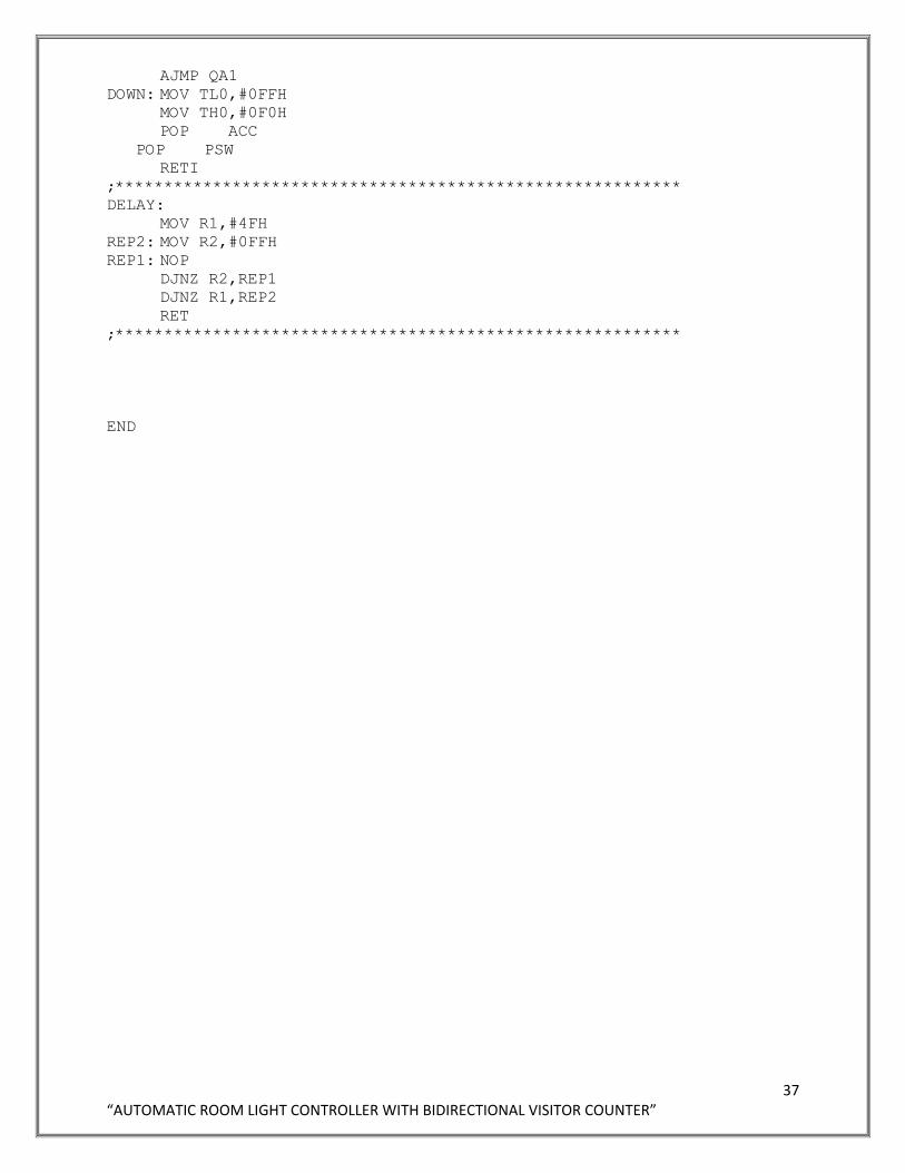
AJMP QA1 DOWN: MOV TL0,#0FFH MOV TH0,#0F0H POP ACC POP PSW RETI ;********************************************************** DELAY: MOV R1,#4FH REP2: MOV R2,#0FFH REP1: NOP DJNZ R2,REP1 DJNZ R1,REP2 RET ;********************************************************** END

38 “AUTOMATIC ROOM LIGHT CONTROLLER WITH BIDIRECTIONAL VISITOR COUNTER”
CHAPTER:- 8
FUTURE EXPANSION

39 “AUTOMATIC ROOM LIGHT CONTROLLER WITH BIDIRECTIONAL VISITOR COUNTER”
FUTURE EXPANSION:-
1. By using this circuit and proper power supply we can implement various applications Such as fans, tube lights, etc.
2. By modifying this circuit and using two relays we can achieve a task of
opening and closing the door.
40 “AUTOMATIC ROOM LIGHT CONTROLLER WITH BIDIRECTIONAL VISITOR COUNTER”
CHAPTER: - 9 ADVANTAGES & DISADVANTAGES & APPLICATION,

41 “AUTOMATIC ROOM LIGHT CONTROLLER WITH BIDIRECTIONAL VISITOR COUNTER”
ADVANTAGES & DISADVANTAGES & APPLICATION,
Advantages:-
1. Low cost 2. Easy to use 3. Implement in single door
Disadvantages:-
1. It is used only when one single person cuts the rays of the sensor hence it cannot be used when two
person cross simultaneously. • Application:-
1. For counting purposes 2. For automatic room light control
42 “AUTOMATIC ROOM LIGHT CONTROLLER WITH BIDIRECTIONAL VISITOR COUNTER”
CHAPTER: - 10 REFERENCE BOOKS & WEBSITE
43 “AUTOMATIC ROOM LIGHT CONTROLLER WITH BIDIRECTIONAL VISITOR COUNTER”
• Reference Books
1. Programming in ANSI C: E BALAGURUSAMY 2. The 8051microcontroller and embedded systems: MUHAMMAD ALI MAZIDI 3. JANICE GILLISPIE MAZIDI 4. The 8051 microcontroller: KENNETH J. AYALA
Website
1. www.datasheets4u.com 2. www.8051.com


![[PPT]“AUTOMATIC ROOM LIGHT CONTROLLER WITH ... · Web viewAUTOMATIC ROOM LIGHT CONTROLLER WITH BIDIRECTIONAL VISITOR COUNTER Objective: To make a controller based model to count](https://static.fdocuments.us/doc/165x107/5ac17a9b7f8b9ac6688d693f/pptautomatic-room-light-controller-with-viewautomatic-room-light-controller.jpg)