AUTOMATIC PAPER FOLDING MACHINE - Welcome … PAGE 3 OPERATORS INTRODUCTION TO THE MORGANA DOCUFOLD...
23
ISSUE APRIL 2001 OPERATORS MANUAL AUTOMATIC PAPER FOLDING MACHINE Morgana Systems Limited Snowdon Drive Winterhill Milton Keynes Buckinghamshire MK6 1AP United Kingdom Telephone: ( 01908 ) 608888 Facsimile: ( 01908 ) 692399 90-013
-
Upload
doankhuong -
Category
Documents
-
view
219 -
download
3
Transcript of AUTOMATIC PAPER FOLDING MACHINE - Welcome … PAGE 3 OPERATORS INTRODUCTION TO THE MORGANA DOCUFOLD...
ISSUE APRIL 2001
OPERATORS MANUAL
AUTOMATIC PAPER FOLDING
MACHINE
Morgana Systems Limited Snowdon Drive Winterhill Milton Keynes Buckinghamshire MK6 1AP United Kingdom Telephone: ( 01908 ) 608888 Facsimile: ( 01908 ) 692399
90-013
PAGE 2 PA P E R
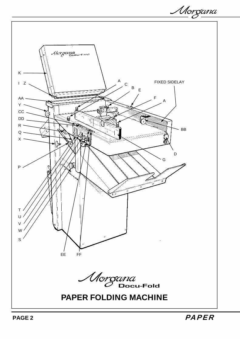
PAPER FOLDING MACHINE
K
I Z
AA
A C
B E
F A
FIXED SIDELAY
BB
D G
FF EE
S
W
V
U T
Y
CC
DD
R Q
X
P
F O L D E R PAGE 3
OPERATORS INTRODUCTION TO THE MORGANA DOCUFOLD The Morgana Docufold is a brand new concept paper-folding machine. Designed to be used in today's environment of document production, the Morgana Docufold can be used by non-skilled personnel by following this easy to use operators guide. There are very few operator adjustments required on the machine and our KWIK START section will get you started very quickly, but we do recommend that you take a little time to read this manual, to ensure that you fully understand the machine. We have also included a TIPS & TROUBLE SHOOTING section. Be sure to read this section before calling a service engineer to avoid any unnecessary expense. On the Docufold the fold plates and Delivery Roller will move automatically according to the type of fold selected. Please be aware that different weights, humidity, temperature or the grain direction of the paper may make the paper fold in a different position according to the material. Some manual adjustment may sometimes be necessary to obtain the exact fold plate position for each type of paper. KWIK START GUIDE: 1. Set the paper gate gap (knob B) to two thickness of the paper to be folded. 2. Place the paper to be folded onto the loading table against the fixed side lay. 3. Unclamp the moving side lay (knobs A) and slide up against the side of the paper but allow
approximately a 1/2 mm or 1/64 inch gap between the moving side lay and the paper. 4. Clamp the backstop (F) onto the moving side lay at the back of the paper stack.
(Note) Do not attempt to load too many sheets onto the loading table during set up as this may affect the feeding operation.
5. Make sure you have power to the machine and that knob (S) is turned onto the ON position.
6. Push switch (W) downward to set up position. 7. Slide the sheet-measuring device (BB) up to the block of paper to be folded. 8. Look at the diagram on the moving side (G) lay showing the various fold types. Select the
type of fold that you require to make by turning knob (V), for example select SL for Letter fold.
9. Lift switch (W) to the middle position (Run) 10. Press the system switch (T) and allow the machine the machine a few seconds to reach its
optimum speed. 11. Press the feed switch (U) down to pulse and the machine will feed three sheets for checking.
PAGE 4 PA P E R
12. ‘Check’ will appear on the control panel display. If the check sheets are folded correctly, move the feed switch (U) to the off position.
13. Zero the counter by pressing the set-up switch (W) upwards. If you require to batch, the
Docufold provides the facility to batch in denominations of 10’s from 10 to 1000. To set batch, you can select the requires batch number by turning the feed switch (U) to off& then rotating the select knob (V) until the required batch quantity appears in the control panel display.
14. Push the feed switch down to pulse to start the machine feeding the paper.

F O L D E R PAGE 5
MORGANA DOCUFOLD OPERATOR INSTRUCTIONS
SIDE LAY Place a single sheet of the job onto the loading table. Release the side lay clamp screws (A) and slide the side lay just up to the sheet so that there is about half a millimetre clearance or 1/64 inch Tighten the clamp screws. PAPER GATE Adjust the height of the paper gate using knob (B) (clockwise to lower, anti-clockwise to raise) so that the clearance above the vacuum roller is two thicknesses of the paper to be folded. Do not make this adjustment, when the face of the paper gate is above a hole in the vacuum roller, if it is, rotate the vacuum roller by hand to bring the metal between holes below the paper gate. On this machine, the paper gate is fixed in an optimum position and cannot be moved backwards and forwards (horizontally). SUCTION OPENING The suction slot inside the suction drum, may be adjusted by releasing knob (C) and swinging the knob in the desired position. Lighter stocks including bond will run best with the knob set to the left. For heavier stocks and curled-up stock, move the knob (C) to the right until a satisfactory position is obtained. AIR DISTRIBUTION KNOB (D) Depending on the length of the sheet, the air distribution knob (D) should be rotated to supply the air to the correct ports as follows - Position 1 - This is for short sheets A5 or 8" long with only port 1 open Position 2 - This is for sheets A4 or 11" long with the front port and port 2 open Position 3 - This is for the longest sheets A3 or 17" with the front port and port
3 open. Position 0 - In this position, only port 2 is open and can be used on long sheets
with the curl up where you need to blow air into the centre of the stack.
These setting positions are only a guide and some experimentation may obtain a better result with non-standard settings. (Note) Position 1 feeds most paper stocks and sizes; thus the air distribution knob can be left in this position for most jobs.

PAGE 6 PA P E R
AIR SEPARATION KNOB (E) This knob controls the amount of air that is fed to the paper. The machine would normally run with this knob set at the 'High' position. If the machine is run with less than approximately 20 sheets on the loading table, or running the job to the last sheet, this knob should be set to the low position. BACK STOP (F) This is placed up to the end of the paper stack and clamped to the moving side lay (G). SHEET MEASURING (BB) When pushing set-up switch (W) down to set-up, the position of the sheet-measuring device will be displayed on the control panel display. It will measure the length of a stack of paper to an accuracy of 0.1 mm. By pushing the sheet-measuring device up to the back of the stack of paper, it will allow the Docufold to calculate the fold length according to the type of fold selected. Note: - If the digit after the decimal place flashes, it is measuring between 0.1 of a millimetre andis not a malfunction. Always push the sheet-measuring device against the paper stack when adjusting fold types. FOLD PLATES ALWAYS UNPLUG POWER CONNECTIONS BEFORE REMOVING FOLD PLATES. Fitting Fit the fold plates into their respective positions (long fold plate upper and short plate lower), by locating the front pins (I) into the long slots and carefully sliding forwards (without twisting) until the rear pins can be located into the short slots. When fully in position, pull down the fold plate to lock into position. Connect the push-in power connectors – short lead to plate 1 (upper) & long lead to plate 2 (lower). Settings The fold plate lengths are set automatically. Fold plate Tilt See roller tilt.

F O L D E R PAGE 7
Manual & Fine Adjustment The fold plate length can be adjusted manually. You may need to make this adjustment to achieve the exact correct length of fold. Button (CC) will select the upper fold plate & button (DD) the lower fold plate. To make a manual adjustment to the position of the upper fold plate, press and hold the upper fold plate button (CC). The dimension of the upper fold plate will now be displayed in the control panel. Note: - The upper fold plate shows the dimension of the front edge of the paper to the first fold, the lower fold plate shows the dimension from the first fold to the second fold. By turning the select knob (V) whilst still pressing and holding the upper fold plate button (CC) the fold length of the upper plate can be lengthened or shortened. Turning the select knob (V) clockwise will lengthen the fold plate length and by turning anti-clockwise it will shorten the fold plate length. The digits before the decimal point shown in the display are in millimetres, each ‘click’ of the select knob (V) represents increments of 0.1 of a millimetre. To adjust the position of the lower fold plate, press & hold the lower fold plate button (DD) andadjust the length as described above. When you have adjusted the fold length dimension, move switch (W) up to the Run position. The plates will then position themselves according to the fold lengths you have selected. With switch (W) in the Run position the left hand side of the control panel will display the letter‘U’ which indicates a user setting followed by a letter that indicated the fold type. For example the letters ‘UL’ would indicate a User setting based on a Letter fold and the letters ‘UH’ would indicate a User setting based on a Half fold. To check the fold position after making a manual or fine adjustment, press the system switch (T) and then press the feed switch (U) down. The machine will feed 3 check sheets and stop. After checking the 3-rd sheet, if the fold position is correct, move the feed switch up to the off position and then immediately down to the pulse position and the machine will start to operate. If after checking and further plate positioning is required, repeat the above procedure. The final fold plate and delivery stacker settings can be ‘stored’ for retrieval at a later date, see ‘To Store A Programme’.

PAGE 8 PA P E R
Roller Tilt Lever (AA) should always be set in the ‘0’ (square) position. To adjust folding out of square you can move the roller assembly in the + or – direction by releasing knobs (Y) and moving lever (AA) – always re-tighten Knobs (Y).
+ -

F O L D E R PAGE 9
Stacking Roller The stacking roller will adjust automatically according to the fold type selected. Manual or fine adjustment for the position of the stacker roller can be made by pressing and holding the stacker roller button (EE) on the top of the control panel. ‘Roll’ and a digit from 1 to 9 will appear in the display panel. The higher the number – the further down the belt stacker bed the roller will be. To adjust the stacking roller position up or down, press the stacking roller button (EE) and turn the select knob (V) to one of the pre-set positions 1 to 9. You should adjust the roller position so that when the work is stopped by the stacking roller, it lies flat on the delivery without lying on the sloping plate (R) and without the green belts showing between the sloping plate (R) and the folded sheet. To Store A Program After making a manual adjustment or fine adjustment to either the upper fold plate, lower fold plate or the stacking roller position, you can store the setting for retrieval at a later date. This can be useful when jobs need to be repeated. Press switch (W) down to the set-up position, using the select knob turn until you reach a ‘P’ witha single digit number next to it. You have from ‘P1’ to ‘P6’ to select and can store up to six programmes. When you have selected a ‘P’ number, press and hold the feed switch (U) down until ‘StorEd’ appears in the display panel. To select a ‘P’ programme at a later date, press set-up switch (W) down select the relevant ‘P’ number by rotating the select knob (V) and push the set-up switch (W) to Run. Press system switch (T) & move the feed switch (U) to Pulse. Emergency Stop Switch (S) This switch also serves as the main isolator. It is important that the machine is switched off at the end of the days running, press this switch to isolate the machine. To switch back on, rotate the switch head clockwise. Main Switch (T) The main switch (T) will run the whole machine. This switch incorporates a circuit that switches off every 100 seconds whilst the feed switch U is in the off position. The main switch may disengage seemingly at random but this is a normal function and may be instantly re-engaged.

PAGE 10 PA P E R
Feed Switch (U) Switches the feed on and off. Never leave in the pulse or stream position when main switch (T) is off. This switch is used to select the type of feed, either pulse or stream. In the central pulse position the feeder pauses between each sheet and allows a gap of 160 mm between each sheet as they enter the fold rollers. This gap prevents sheets over lapping inside the fold plates, which lessens the chance of static being generated and will decrease paper jams. Zigzag / concertina, engineering and gate folds can only be run on pulse. By holding switch (U) down, the feed mode will switch to stream feed which will feed paper with little or no gap between the sheets. Stream feed will increase productivity but folding accuracy may be slightly impaired. You can only use stream on letter, half or double parallel folds. The pulse feed will cope with all types of fold including perforating. Batch Knob (V) The batch knob is a rotary switch and turning the knob slightly so that it moves one position will cause the display to show the set batch quantity. Moving the knob further will change the batch quantity in multiples of 10 up to 990. Stopping the feed in the middle of a batch will not affect the batch. When the machine batches, the feed will stop and the display will show the batch quantity with a series of dashes. Feeding will resume after a short period. If batching is not required, turn the batch knob (V) until it reads 0 in the display panel. When 0 is shown afterturning batch knob (V) the counter will only total count. Overlap The machine has a built in system that will detect any sheet that overlaps another sheet by at least 20mm. When this happens, feeding will stop and the main switch will switch off, preventing serious jams and the display will show 'O-LAP'. Note that this is not a double detector and will not detect all double sheet feeds. However the overlap system is an indication of a tendency to double sheet feed and therefore the paper gate should be lowered slightly and the paper stack should be fanned out more thoroughly. Speed Control (X) The machine has two running speeds, which are selected by the handle (X). Pushing the handle sharply into the machine will select the fast speed. Pulling the handle sharply outwards will select the slow speed. The slow speed is recommended when running work that is difficult to stack, for example when perforating or folding an engineering type fold.

F O L D E R PAGE 11
PLUG-IN PERFORATOR The plug in perforator unit is used for perforating scoring and when folding card cover stock and should be stored on the rear stowage hooks. ALWAYS UNPLUG POWER CONNECTORS BEFORE REMOVING FOLD PLATES OR PLUG-IN PERFORATOR. Remove the second fold plate and fit the catch tray in position by hooking it over the opening for the second fold plate. The plug in perforator unit then locates the same as thefold plate and again, take care not to twist when fitting into position. You may need to turn the hand wheel and push the perforator unit inwards to engage the drive gear. Plug in the lower fold plate power connector into the perforator unit. ‘PerF in’ will appear in the display panel. For all applications, the unit is set on the bench using the scale to indicate positions of the blades and hubs. It is important to spread the hubs evenly across the width of the work to reduce the risk of paper jams. When perforating or scoring without folding, the upper fold plate must be removed and replaced with the lower fold plate. Ensure that the tilt roller is at zero, plug in the upper plate connector into the lower plate. To prevent damage to the unused upper plate when scoring or perforating, store safely on the stowage hooks at the reverse side of the machine. Press set-up switch (W) down and then up to the Run position, the built in deflector on lower fold plate will close automatically to the deflect position. Note: - the Docufold will automatically recognise that the lower plate is in the upper plate position and that the plug-in perforator unit is in the lower plate position. You do not need to measure the paper length. Start the machine with the main switch (T), and select slow speed by pulling out lever (X) sharply. Press the feed switch (U) to pulse. The machine will feed sheets for checking and will display ‘Perf 3’ if the counter has been set to zero. To run the job switch feed (U) to off and then pulse. Note: - Always run perforating or scoring jobs on pulse feed. FITTING PERFORATER BLADES The perforator blades are split into two matching halves and are fitted to the upper hubs as shown in the drawing using the four screws supplied.

PAGE 12 PA P E R
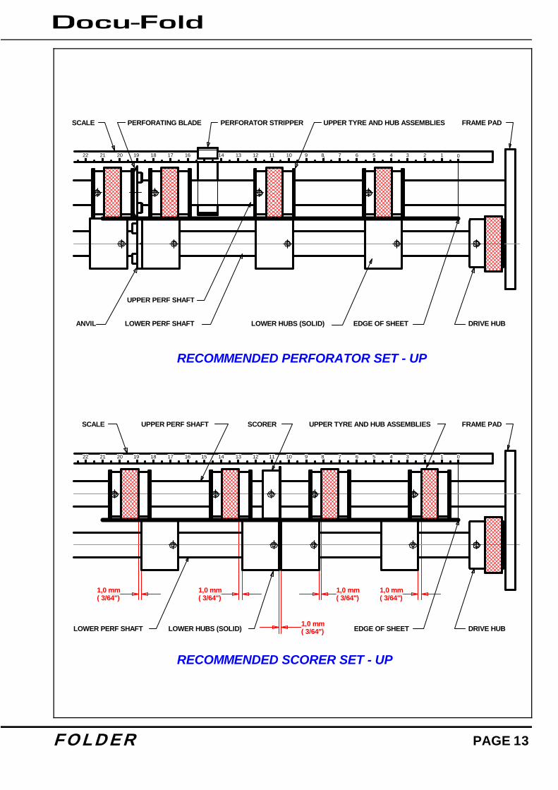
F O L D E R PAGE 13
UPPER TYRE AND HUB ASSEMBLIES
LOWER HUBS (SOLID)LOWER PERF SHAFT
FRAME PADUPPER PERF SHAFT
DRIVE HUB
1,0 mm( 3/64")
EDGE OF SHEET1,0 mm( 3/64")
1,0 mm( 3/64")
RECOMMENDED SCORER SET - UP
SCALE
1,0 mm( 3/64")
1,0 mm( 3/64")
SCORER
1522 21 20 19 18 17 16 4 3 2 1 0567891011121314
DRIVE HUB
SCALE
RECOMMENDED PERFORATOR SET - UP
EDGE OF SHEET
FRAME PAD
UPPER PERF SHAFT
LOWER HUBS (SOLID)LOWER PERF SHAFT ANVIL
PERFORATING BLADE PERFORATOR STRIPPER UPPER TYRE AND HUB ASSEMBLIES
22 21 20 19 18 17 16 4 3 2 1 0567891011121314

PAGE 14 PA P E R
SETTING PERFORATORS Upper and lower hubs can be positioned on the shaft by unscrewing the 2mm-grub screw. Slide the hub with the blade attached along, the shaft into position to correspond to the work using the scale as a guide. For example, to perforate 20mm from the edge of an A4 sheet, you would set the blade at 190mm (210 minus 20). When positioned re-tighten the 2mm-grub screw. Important - Do Not Over Tighten This Grub Screw Slide the hub with the anvil, up to the perforator blade and the remaining upper and lower hubs, set as the drawing, remembering to spread them to support the sheet fully across its width. Clip the perforator stripper adjacent to the upper hub as shown. Plug the unit into position, fit the sheet smoother into position to hold the sheets down and run the machine at the slow speed to check position. Adjust the backstop and side guide to suit the work. For work longer than the backstop will allow, remove the backstop and use the extended backstop that is located underneath the catch tray. There is a full range of perforator blades available as follows: For fine perforation 56 tooth - Part Number 1.99-41 For Paper 28 tooth - Part Number 1.99-12 For heavier Stock 20 tooth - Part Number 1.99-10 For use with blades Anvil - Part Number 1.99-35 Slitter set for cutting - Part Number 1.99-13 SCORING It is possible to score work using the plug in perforator. The scorers are split in two halves, fitted to the upper shaft and set as shown in the drawing using the scale on the unit as a guide to position. The lower hubs are moved up to but just clear of the scoring blade. The actual gap is critical and may require some experimentation to obtain a satisfactory score line. As with perforating, the remaining hubs must be spread to supportthe sheet fully across its width. Scorers available: Type A Part Number 6.99-05 for most card Type B Part Number 6.99-06 for deep score Type D Part Number 6.99-09 for paper

F O L D E R PAGE 15
FOLDING CARD For best results, the card material should always be printed cross grain as this causes less resistance when folding. Pre scoring of card stock is also recommended By using the plug in perforator unit to deliver card, the problem of the stock curling will be minimised. Put the upper plate into the upper plate position and the plug-in perforator unit into the lower plate position. Plug in power connectors - upper into upper fold plate and lower into perforator unit. Set the backstop, sheet measuring device and side guide to suit the work. Press the switch (W) down to Set-up and then up to Run. Plate 1 will automatically move to half the length of the stack of cover stock provided the sheet measuring device (AA) is in position. Fine adjustments may be necessary to upper plate as described in ‘Fold Plate Manual / Fine Adjustment’. It is recommended that when folding card, the machine be set to batch after twenty sheets, which will allow easy off loading. For longer runs an optional rear delivery belt stacker (Assy. No. 9-09-01) is recommended to be used. In the event of a paper jam, the sensor will cut out the main switch. The main fold rollersare linked to a clutch, which will prevent sheets continuing to feed. PAPER JAMS If for some reason a piece of paper jams in the machine, remove and check inside the foldplates. If there is paper jammed around the fold rollers take hold of a roller and wind them by hand to remove the jam. If it is impossible to wind the roller by hand, remove the roller assembly as described below. After clearing a paper jam, always check inside the fold plate (see Fold Plate Section) to make sure no torn pieces of paper are jammed inside the plate. ROLLER ASSEMBLY - REMOVAL The complete roller assembly unit can be removed from the machine simply by unscrewing the knobs (Y) on each side and taking hold of the rear roller and lifting out the unit. This is beneficial to clear paper jams, to clean the roller and for maintenance. With the roller assembly removed, the safety circuit prevents the machine from running. Replace the roller unit in the reverse sequence. Clean the rollers with a stiff brush between the grooves using QD wash supplied by Morgana.
PAGE 16 PA P E R
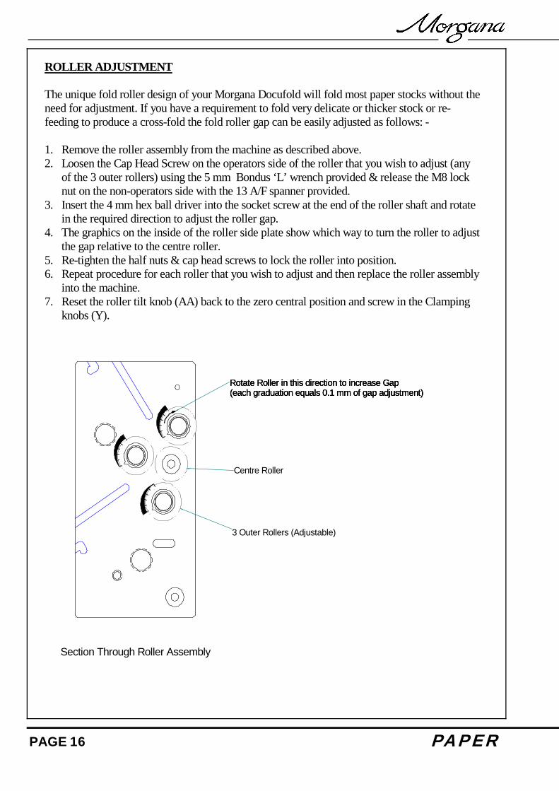
ROLLER ADJUSTMENT The unique fold roller design of your Morgana Docufold will fold most paper stocks without the need for adjustment. If you have a requirement to fold very delicate or thicker stock or re-feeding to produce a cross-fold the fold roller gap can be easily adjusted as follows: - 1. Remove the roller assembly from the machine as described above. 2. Loosen the Cap Head Screw on the operators side of the roller that you wish to adjust (any
of the 3 outer rollers) using the 5 mm Bondus ‘L’ wrench provided & release the M8 lock nut on the non-operators side with the 13 A/F spanner provided.
3. Insert the 4 mm hex ball driver into the socket screw at the end of the roller shaft and rotate in the required direction to adjust the roller gap.
4. The graphics on the inside of the roller side plate show which way to turn the roller to adjust the gap relative to the centre roller.
5. Re-tighten the half nuts & cap head screws to lock the roller into position. 6. Repeat procedure for each roller that you wish to adjust and then replace the roller assembly
into the machine. 7. Reset the roller tilt knob (AA) back to the zero central position and screw in the Clamping
knobs (Y).
Rotate Roller in this direction to increase Gap(each graduation equals 0.1 mm of gap adjustment)
Section Through Roller Assembly
Rotate Roller in this direction to increase Gap(each graduation equals 0.1 mm of gap adjustment)Rotate Roller in this direction to increase Gap(each graduation equals 0.1 mm of gap adjustment)
Centre Roller
3 Outer Rollers (Adjustable)

F O L D E R PAGE 17
SENSOR CLEANING The sensors to detect and count the sheets are located on the end of the ball holder just next to the fold roller unit. If the counter is failing, the sensors can be accessed for cleaning by removing the roller assembly as described above. Clean by using a soft brush or damp cloth. FOLD PLATES - M AINTENANCE The fold plates can be opened up for maintenance, cleaning, etc by removing the lock knob (H) and removing the two bolts (Z). The fold plate will then open up to enable paper jams to be removed or cleaning.

PAGE 18 PA P E R
FOLDING TIPS AND TROUBLE SHOOTING: SHEETS DIFFICULT TO FEED Check that you have not got too many sheets in the feeder. Heavy-coated stock will not feed as high a pile as for example 80-gsm copier paper. Make sure the moving side lay is not pushed in too tightly against the paper. Similarly, if the moving side lay is set too far away from the paper stack, this will allow the air to escape instead of blowing through the paper. Make sure that the gap under the paper gate (B) is not set too low. Turn the Air separation knob (E) to the high position. Make sure that air distribution knob (D) is set correctly. If the paper width varies you may need to trim the sheets to the same size. If the paper is curling upwards the suction drum may not be able to pull the sheet downward to wrap around the drum for efficient feeding. You may need to bend the sheets downward prior to loading. DOUBLE SHEET FEEDING Make sure the gap under the paper gate (B) is not set too high. Make sure the air distribution knob (D) and the air separation knob (E) are at the correct setting. In extreme cases you may need to separate the sheets prior to loading. Make sure you run on Pulse not Stream. FOLD IS NOT SQUARE OR CONSISTANT Check the sheets are all exactly the same size and are square before folding as you can only fold accurately if the material is consistent. Make sure you have no foreign bodies such as fragments of torn paper inside the fold plates or the fold rollers. Check that the fold plates are locked and located securely and that the roller tilt mechanism is set to zero and locked.

F O L D E R PAGE 19
PAPER WILL NOT STACK CONSISTENTLY: Make sure the feed is consistent before attempting adjustments to the stacker. Set the stacking roller position as described in the manual. Sometimes a small repositioning of the roller will improve the stacking. See Stacking Roller. If the paper is too curly when being delivered, place the catch tray and plug in perforating unit with blades disengaged into position and deliver out the back. This applies to single fold applications only. If two folds are required, you may need to reduce the weight of stock to achieve the desired results. PAPER WILL NOT DEFLECT WHEN USING ONE FOLD OR PERFORATING: Check to make sure that the second plate is being used as the deflector. Make sure that the plate is located securely and that the deflector bar is wound right to the end. Set the tilt roller mechanism to zero. Check that the material is not too heavy to deflect. TOTAL AND BATCH COUNTER NOT WORKING: Clean the sensors as described in the manual. O-LAP KEEPS APPEARING ON COUNTER BOARD If the overlap keeps tripping in and cutting off the machine, first check you are not feeding doubles and reset the feeder. Overlap tripping can also mean that the machine is slowing slightly which may mean the material is too heavy. Check that you have no foreign bodies or torn paper stuck inside the plates or machine. ‘NO PLATE’ IN DISPLAY Check fold plate or plug in perforator power connectors. MACHINE WILL NOT RESET
PAGE 20 PA P E R
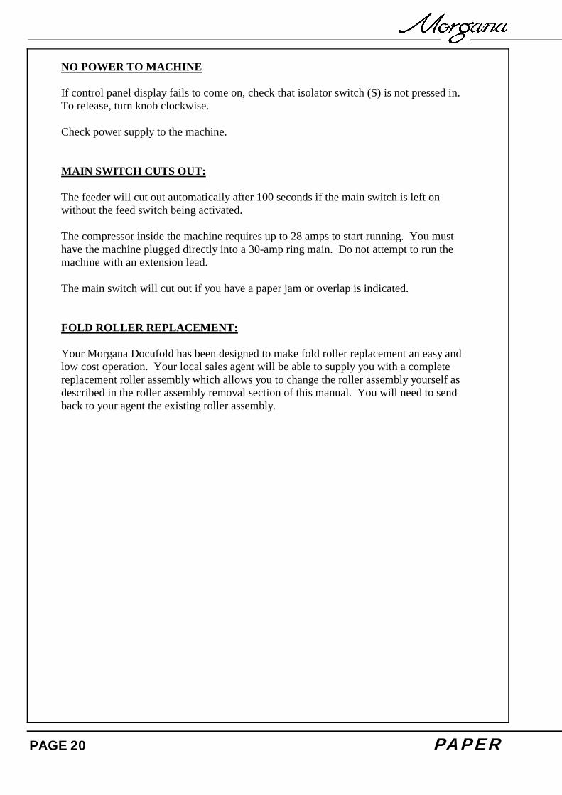
NO POWER TO MACHINE If control panel display fails to come on, check that isolator switch (S) is not pressed in. To release, turn knob clockwise. Check power supply to the machine. MAIN SWITCH CUTS OUT: The feeder will cut out automatically after 100 seconds if the main switch is left on without the feed switch being activated. The compressor inside the machine requires up to 28 amps to start running. You must have the machine plugged directly into a 30-amp ring main. Do not attempt to run the machine with an extension lead. The main switch will cut out if you have a paper jam or overlap is indicated. FOLD ROLLER REPLACEMENT: Your Morgana Docufold has been designed to make fold roller replacement an easy and low cost operation. Your local sales agent will be able to supply you with a complete replacement roller assembly which allows you to change the roller assembly yourself as described in the roller assembly removal section of this manual. You will need to send back to your agent the existing roller assembly.

F O L D E R PAGE 21
PAGE 22 PA P E R
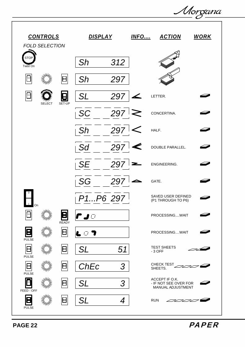
Sh 297
SL 297
SC 297
Sh 297
Sd 297
SE 297
SG 297
P1...P6 297 SAVED USER DEFINED(P1 THROUGH TO P6)
PROCESSING....WAIT
PROCESSING....WAIT
SL 51
ChEc 3
SL 3
SL 4
PULSE
PULSE
PULSE
CONTROLS ACTION WORK
ACCEPT IF O.K. - IF NOT SEE OVER FOR MANUAL ADJUSTMENT
CHECK TESTSHEETS.
TEST SHEETS- 3 OFF
RUN
DISPLAY INFO....FOLD SELECTION
I
0
STOP
Twist On
SELECT
On
GATE.
ENGINEERING.
DOUBLE PARALLEL.
CONCERTINA.
LETTER.
HALF.
SET-UP
READY
PULSE
FEED - OFF
Sh 312

F O L D E R PAGE 23
bAt 50
SL 4
Pt1 97.7MANUAL ADJUST(BASED ON STD. FOLD)
UL 10
P1...P6
StorEd
P5 47PULSE
CONTROLS ACTION WORK
STORE
CHOOSE STORE AREA(P1 THROUGH TO P6)
RUN
DISPLAY INFO....
bAt 0 ZERO COUNTZERO BATCH - 2 SECONDS
SET BATCH QUANTITY
RUN
BATCH
SL 200 PULSE - ALL FOLDS
Cont on 200STREAM
PULSE
SL 200STREAM- LETTER- HALF- DOUBLE PARALLEL
PULSE & STREAM
FOLD PLATE & DELIVERYROLLER ADJUSTMENT
MANUAL ADJUST(BASED ON STD. FOLD)
roLL 1MANUAL ADJUST(BASED ON STD. FOLD)
PROGRAM
SELECT
SELECT
SELECT
SELECT
ZERO COUNT
NOTE DISPLAY CHANGEU = USER SETTINGL = FOLD TYPE
PULSE
READY
SET - UP
READY
Pt2 98.9Pt2
Pt1
Roller
SELECT