
Automatic Optimization Computational Method for ... · Automatic Optimization Computational Method...
8
Automatic Optimization Computational Method for Unconventional S.W.A.T.H. Ships Resistance Stefano Brizzolara and Giuliano Vernengo Abstract—The paper illustrates the main theoretical and computational aspects of an automatic computer based procedure for the parametric shape optimization of a particular unconventional hull typology: that for a catamaran S.W.A.T.H. ship. The goal of the integrated computational procedure is to find the best shape of the submerged hulls of a new U.S.V. (Unmanned Surface Vehicle) S.W.A.T.H. (Small Waterplane Area Twin Hull) vessel, in terms of minimum wave pattern resistance. After dealing with the theoretical aspects the papers presents the numerical aspects of the main software module of the automatic procedure, which integrates a parametric generation routine for innovative and unconventional S.W.A.T.H. (Small Waterplane Area Twin Hull) vessel geometry, a multi-objective, globally convergent and constrained, optimization algorithm and a Computational Fluid Dynamic (C.F.D.) solver. The integrated process is able to find the best shape of the submerged hull of the vessel, subject to the total displaced volume constraint. The hydrodynamic computation is carried out by means of a free surface potential flow method and it is addressed to find the value of wave resistance of each hull variant. Results of the application of the described computational procedure are presented for two optimization cases and the obtained best shapes are compared with a conventional one, featuring a typical torpedo-shaped body, proving the effectiveness of the method in reducing the resistance by a considerable extent, in the order of 40 percent. Keywords—S.W.A.T.H., B.E.M., Wave Resistance, Parametric Modeling, Optimization, Genetic Algorithms I. INTRODUCTION Computer Assisted Optimization has become a very interesting numerical engineering discipline which allows to explore and obtain innovative solutions in many different fields of application [1] [2]. Its implementation in naval architecture (i.e. the design discipline that study the shape of a ship hull with respect to stability, strength, resistance and propulsion) becomes very effective especially when it is coupled with a parametric approach for the mathematical definition of the hull surfaces, in order to control their shape with a limited number of variables. Naval architects, by tradition, are used to optimize ship hull forms by mean of model tests in towing tank, on scaled geosym models. Nowadays the model scale experiments can be substituted by modern Computational Fluid Dynamic (C.F.D.) codes that are able to solve with a good accuracy Manuscript received April 7, 2011: Revised version received ??????? ????,. This work was supported in part by N.U.R.C. (NATO Undersea Research Center) of La Spezia. S. Brizzolara is with the University of Genova, responsible of the Marine C.F.D. Group, via Montallegro, 1, 16145 Genova. Italy. (phone: +39-010-353.2386; fax: +39-010-353.2127; e-mail: Stefano.Brizzolara@ unige.it). G.Vernengo, is with the University of Genova, PhD Student of the Marine C.F.D. Group via Montallegro, 1, 16145 Genova. Italy. (phone: +39-010-353.2435; e-mail: [email protected]). [3] the turbulent viscous flow around a hull advancing at a given speed in calm water. Numerical models can considerably speed up the optimization time, but the mode of selecting the variation of the hull form is still based on a trial and error scheme, highly reliant on an expert evaluation and interpretation of C.F.D. results, which does not facilitate the convergence on the optimal solution. Fig. 1: Main elements of a standard S.W.A.T.H. vessel Small Waterplane Area Twin Hull (S.W.A.T.H.) ships are a special concept of hull typology and configuration (see Fig. 1) featuring two or more slender struts that are actually piercing the free surface, while the major part of the displaced volume is concentrated well below the free surface in torpedo-like underwater bodies. The major advantage of this hull typology is its superior seakeeping ability. Another benefit of this type of vessel is a high deck area compared to their displacement. A typical drawback, though, is the higher resistance in calm water with respect to equivalent mono-hulls or catamarans. The work presented in this paper is part of a project in collaboration with N.U.R.C. (N.A.T.O. Undersea Research Center, in La Spezia), whose aim has been to design a new small size (about 6m long) Unmanned Surface Vehicle (U.S.V.) with extended operability in rough sea conditions with respect to the existing solutions. For all the above, S.W.A.T.H. type of hull was considered as the best solution, but in order reduce the typical high powering requirement at relatively high speed, a dedicated optimization study of the underwater hull form has been performed. To this scope an integrated, computer assisted, optimization procedure has been implemented, interfacing together a state of the art optimization algorithm, a 3D B- surface parametric geometry modeler and a free surface potential flow C.F.D. solver. The idea derives from a previous successful attempt [4] of integrated hydrodynamic optimization of S.W.A.T.H. hull forms, that used a fully analytical description of the hull surface, a differential evolution algorithm and the same C.F.D. solver. This new study has introduced and experimented a more general multi-objective and INTERNATIONAL JOURNAL OF MATHEMATICAL MODELS AND METHODS IN APPLIED SCIENCES Issue 5, Volume 5, 2011 882
Transcript of Automatic Optimization Computational Method for ... · Automatic Optimization Computational Method...
Automatic Optimization Computational Method
for Unconventional S.W.A.T.H. Ships Resistance
Stefano Brizzolara and Giuliano Vernengo
Abstract—The paper illustrates the main theoretical and
computational aspects of an automatic computer based procedure
for the parametric shape optimization of a particular
unconventional hull typology: that for a catamaran S.W.A.T.H.
ship. The goal of the integrated computational procedure is to find
the best shape of the submerged hulls of a new U.S.V. (Unmanned
Surface Vehicle) S.W.A.T.H. (Small Waterplane Area Twin Hull)
vessel, in terms of minimum wave pattern resistance.
After dealing with the theoretical aspects the papers presents the
numerical aspects of the main software module of the automatic
procedure, which integrates a parametric generation routine for
innovative and unconventional S.W.A.T.H. (Small Waterplane
Area Twin Hull) vessel geometry, a multi-objective, globally
convergent and constrained, optimization algorithm and a
Computational Fluid Dynamic (C.F.D.) solver. The integrated
process is able to find the best shape of the submerged hull of the
vessel, subject to the total displaced volume constraint. The
hydrodynamic computation is carried out by means of a free
surface potential flow method and it is addressed to find the value
of wave resistance of each hull variant. Results of the application
of the described computational procedure are presented for two
optimization cases and the obtained best shapes are compared with
a conventional one, featuring a typical torpedo-shaped body,
proving the effectiveness of the method in reducing the resistance
by a considerable extent, in the order of 40 percent.
Keywords—S.W.A.T.H., B.E.M., Wave Resistance, Parametric
Modeling, Optimization, Genetic Algorithms
I. INTRODUCTION
Computer Assisted Optimization has become a very
interesting numerical engineering discipline which allows to
explore and obtain innovative solutions in many different
fields of application [1] [2]. Its implementation in naval
architecture (i.e. the design discipline that study the shape of
a ship hull with respect to stability, strength, resistance and
propulsion) becomes very effective especially when it is
coupled with a parametric approach for the mathematical
definition of the hull surfaces, in order to control their shape
with a limited number of variables.
Naval architects, by tradition, are used to optimize ship
hull forms by mean of model tests in towing tank, on scaled
geosym models. Nowadays the model scale experiments can
be substituted by modern Computational Fluid Dynamic
(C.F.D.) codes that are able to solve with a good accuracy
Manuscript received April 7, 2011: Revised version received ???????
????,. This work was supported in part by N.U.R.C. (NATO Undersea
Research Center) of La Spezia.
S. Brizzolara is with the University of Genova, responsible of the
Marine C.F.D. Group, via Montallegro, 1, 16145 Genova. Italy. (phone:
+39-010-353.2386; fax: +39-010-353.2127; e-mail: Stefano.Brizzolara@
unige.it).
G.Vernengo, is with the University of Genova, PhD Student of the
Marine C.F.D. Group via Montallegro, 1, 16145 Genova. Italy. (phone:
+39-010-353.2435; e-mail: [email protected]).
[3] the turbulent viscous flow around a hull advancing at a
given speed in calm water. Numerical models can
considerably speed up the optimization time, but the mode
of selecting the variation of the hull form is still based on a
trial and error scheme, highly reliant on an expert evaluation
and interpretation of C.F.D. results, which does not facilitate
the convergence on the optimal solution.
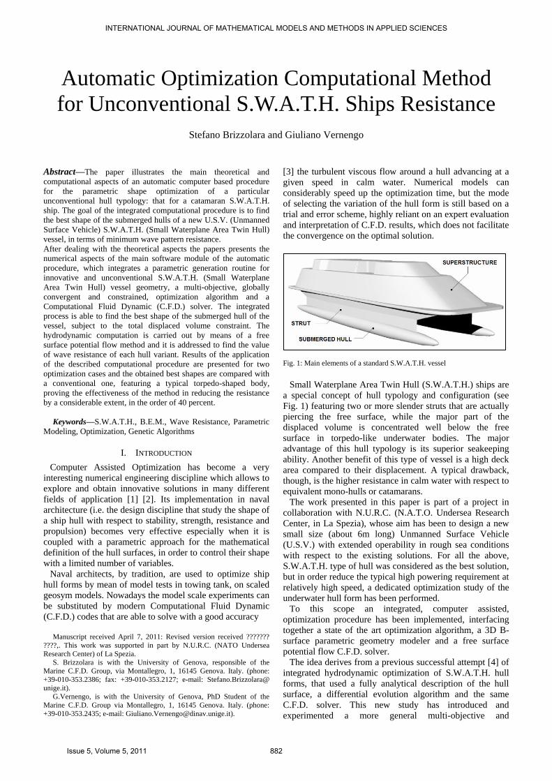
Fig. 1: Main elements of a standard S.W.A.T.H. vessel
Small Waterplane Area Twin Hull (S.W.A.T.H.) ships are
a special concept of hull typology and configuration (see
Fig. 1) featuring two or more slender struts that are actually
piercing the free surface, while the major part of the
displaced volume is concentrated well below the free
surface in torpedo-like underwater bodies. The major
advantage of this hull typology is its superior seakeeping
ability. Another benefit of this type of vessel is a high deck
area compared to their displacement. A typical drawback,
though, is the higher resistance in calm water with respect to
equivalent mono-hulls or catamarans.
The work presented in this paper is part of a project in
collaboration with N.U.R.C. (N.A.T.O. Undersea Research
Center, in La Spezia), whose aim has been to design a new
small size (about 6m long) Unmanned Surface Vehicle
(U.S.V.) with extended operability in rough sea conditions
with respect to the existing solutions. For all the above,
S.W.A.T.H. type of hull was considered as the best solution,
but in order reduce the typical high powering requirement at
relatively high speed, a dedicated optimization study of the
underwater hull form has been performed.
To this scope an integrated, computer assisted,
optimization procedure has been implemented, interfacing
together a state of the art optimization algorithm, a 3D B-
surface parametric geometry modeler and a free surface
potential flow C.F.D. solver.
The idea derives from a previous successful attempt [4] of
integrated hydrodynamic optimization of S.W.A.T.H. hull
forms, that used a fully analytical description of the hull
surface, a differential evolution algorithm and the same
C.F.D. solver. This new study has introduced and
experimented a more general multi-objective and
INTERNATIONAL JOURNAL OF MATHEMATICAL MODELS AND METHODS IN APPLIED SCIENCES
Issue 5, Volume 5, 2011 882

constrained optimization algorithm and a new parametric B-
surfaces definition of the hull geometry.
Each element of the optimization procedure will be better
described in the next section.
II. PROBLEM FORMULATION: SET-UP OF THE OPTIMIZATION
CHAIN
This section would be described the definition of the
problem. In order to give more clearness three different
formulations will be showed: first of all, how the parametric
model works and what are form parameters by which
modify the shape of the hull; then a description of what
method has been used to evaluate hydrodynamics
performances of the vessel; finally, a brief explanation of
the optimization algorithm and a more detailed description
of the complete procedure.
A. Parametric model
The parametric model has been created in a dedicated
environment using the software Friendship-Framework: its
valuable feature concerns with the possibility to have a
connection between some user-defined parameters and the
mathematical description of surfaces as [4],[5],[6].
The basic design activity brought to the definition of two
longitudinally separated and outward canted struts for each
submerged hull, as in the example represented Fig. 4.
Because of the symmetry of the geometry, only a half of
the entire S.W.A.T.H. has been modeled, also in the C.F.D.
code, assigning proper boundary conditions on the
symmetry plane. Moreover, because the purpose of this
work is to optimize the shape with respect to hydrodynamics
performance, only the model of the submerged hull and its
struts have been defined, without modeling the deck and
other elements of the deadworks or the hull appendages.
In this respect, the submerged part of the hull has been
generated as an ellipsoid defined by two geometrically
similar (with a scaling factor) B-Spline curves which
represents its profile shape in the horizontal and vertical
meridian planes, as in the example of Fig. 2. Each
coordinate of the five internal control points (out of 7 used
to actually define the B-spline) of the basic B-spline curve is
a free form parameter which will be changed during the
evolution of the optimization process.
Fig. 2 shows the layout of the control points: the first and
the last one defines the maximum length of the hull; the
second and the sixth can move only in vertical direction, to
regulate the curvature radius at leading and trailing edge of
the curve, respectively; the remaining inner three points are
responsible for the unconventional shape variation, with an
intermediate hollow and two humps.
Fig. 2: Control points of the B-Spline curve type used for the horizontal and
vertical profiles of the S.W.A.T.H. underwater body
The struts, instead, are defined as a wing surface, on the
basis of a 2D transverse section defined, as for airfoils, with
the entrance and exit angles, the value of the maximum
camber and its relative position along the chord, as in the
schematic drawing of Fig. 3. This is the set of free form
parameters assumed for the struts shape modifications.
Fig. 3: Profile parameters for strut sections
Fig. 4 shows the final hull obtained by intersecting the
struts with the underwater body: the generation and
intersection in 3D is performed for each alternative shape
that the optimization algorithm explore, which corresponds
to a given set of the above defined free form parameters.
Fig. 4: Orthogonal views of the parametric model of the S.W.A.T.H.
B. Optimization procedure
As a main difference from the first cited cases of
S.W.A.T.H. hull optimization, a different algorithm has
been used to drive the optimization process, instead of the
previously used differential evolution algorithm, also used
with success by other authors in different applications [11]
[12]. The new optimization strategy features a N.S.G.A.-II
algorithm, first proposed by Deb K. [13]; this algorithm is
based on different level of classification: before the
selection phase, the population is distinguished, following
the principle of non-dominance, several times in order to
create sub-groups which would be useful for the evolution
strategy. As well as common genetic operators, N.S.G.A.-II
make use of some techniques like niching by which a
parameter, called crowding distance, is assigned to each
member to drive the exploration of the free variables space.
The optimization algorithm lead the process showed, as a
high level flowchart, in Fig. 5. It is possible to sub-divide it
in five steps:
1. Selection of the value of input parameters
2. Creation of the parametric model
3. Check of volume constrain
4. Wave resistance computation (evaluation of the
objective function)
5. Evaluation of the objective function
A particular choice has been done on how to handle the
problem constraints: since each evaluation of the cost
function requires about four minutes, in order to reduce
computational time, once the geometry of the has been
generated, hydrostatic calculations are performed and the
volume of the underwater part of the vessel is determined;
the check of its given value is done at this stage: if the
INTERNATIONAL JOURNAL OF MATHEMATICAL MODELS AND METHODS IN APPLIED SCIENCES
Issue 5, Volume 5, 2011 883

deviation from the expected value is out of a small
tolerance, the computational process is stopped and the
design alternative is discarded as unfeasible; otherwise if the
given displacement is respected, the hydrodynamic
computation is continued and the objective function is
evaluated. This could affect in some way the converge
capability of the algorithm, because will create unfeasible
areas in the free variable space, although no particular
problems have been manifested, as will be clear from in the
next section.
In the presented example, it was decided to use eight free
parameters, and hence an initial population of one hundred
individuals, whose free parameters vectors were initially
generated by means of a Sobol algorithm: this allow a
random distribution in the first generation, while ensuring a
quite uniform distribution of them over the design space and
hence a good basis for the successive exploration.
C. BEM method for hydrodynamics analysis
In the following we present the basic theoretical details of
the boundary element method used to solve the potential
flow with free surface around the hull and predict the free
wave pattern formation, and eventually estimate the wave
resistance, which is the most variable and unknown
component of resistance at relatively high speeds, as the
design speed assumed in this study, corresponding to a
Froude number Fn=0,66.
An incompressible irrotational potential flow is assumed
by enforcement of the Laplace equation to the total velocity
potential in the fluid domain bounded by the hull surface SB
and the free surface. An indirect boundary element method,
linearized with respect to the double model flow as
developed in [8] is used as further adapted and successfully
validated in the case of high speed mono- and multi- hull
vessels [3], including the prediction of the dynamic attitude
[8].
In a Cartesian reference frame travelling with the ship at
U constant speed is centered at an arbitrary point on the
intersection of the longitudinal symmetry plane with the
undisturbed free surface (z axis oriented upwards), the total
velocity potential can be written as
xU (1)
where is the perturbation potential with respect to the
uniform incident flow. Both velocity potential functions
must satisfy the Laplace equation in the whole domain:
0,0 (2)
together with the following boundary conditions:
0n
on the hulls (3)
0 on the free surface (4)
2
2
1
2
1 Ug
on the free surface (5)
0, xU for x (6)
namely, the Neumann condition on hulls surfaces (3), the
kinematic and dynamic condition on the free surface (4) and
(5) and the radiation condition for the disturbance upstream
(6); z=(x,y) represents the explicit unknown equation the
define the shape of the wavy free surface.
In our method the free surface boundary conditions (4) and
(5) are linearized using a small perturbation theory, by
which the total velocity potential is considered as the sum
of a main contribution represented by the potential D of
the flow around a double model symmetrical with respect to
the undisturbed free surface, considered as deeply immersed
in the fluid, and the contribution of the new perturbation
potential, due to presence of the wavy free surface.
The double model and the linear free surface potential
flow problems are both numerically solved by a boundary
element method which is based on the discretization of the
boundary surface , namely the hull surface (SH) and the
undisturbed free surface (SF), with a structured set of
quadrilateral planar panels each having constant distribution
of Rankine sources on it.
Defining the influence coefficient vector as the velocity
vector induced at the centroid of panel i by a panel j having
a uniform distribution of sources with constant strength j:
),,()1
( ijijijjjquad
ij
ZYXdSr
(7)
we discretized the boundary conditions (4) and (5),
imposing them on each panel centroid taking into account
for the contribution of any panel on the hull (NH in number)
and on the free surface (NF in number). As a result after
mathematical manipulation of the discretized boundary
conditions written in terms of the double model and
perturbation potential, the following linear system of
equations, in the unknown sources intensities, is obtained:
Hzi
NN
j
ijyiijxiij NiUxnZnYnXFH
,11
(8)
NFiy
bUx
ag
x
Y
xxy
Y
y
x
X
xYbXa
Di
Dii
j
ijDDij
iD
ij
iD
ijiij
NN
j
i
FH
,12)(22
]))((2)(
)(22[
2
2
1
(9)
To compute the derivatives of the potential, a four points
differential operator is used, everywhere on the free surface
in both longitudinal and transversal directions. As known
this operator gives an implicit property of numerical
damping of the disturbance which is used to numerically
enforced the radiation condition (6). The free surface waves
are found by substituting the total velocities calculated over
the free surface panels in the linearized Bernoulli condition
(5).
The wave resistance is found, in this study, by the
integration of the dynamic pressure calculated on each
panel. Other studies [3] used a (numerical) transverse cut
method, to calculate the wave resistance from the energy
content of the generated wave pattern. No attempt were
INTERNATIONAL JOURNAL OF MATHEMATICAL MODELS AND METHODS IN APPLIED SCIENCES
Issue 5, Volume 5, 2011 884

made in this study to use this second method that requires a
preliminary sensitivity study to identify the proper location
of the transverse cut. The S.W.A.T.H. hull attitude was kept
fixed in the computations of this study corresponding to
static one, assuming that the ride control system, with active
fins, would maintain this attitude at the design speed.
Moreover it is believed that the influence of the stabilizer
fins on the resistance might be of secondary effect, and
hence neglected.
D. Validation of the C.F.D. method
The inviscid method outlined in previous section, has been
applied in the case of a S.W.A.T.H. like mono-hull which
was tested in towing tank for the validation study of C.F.D.
methods on similar hulls. In order to compare the total
resistance which follow from towing tank tests, it has been
coupled with a thin boundary layer solver, which hasn’t
been used in the present study. The test case is a mono-hull
of the S.W.A.T.H. type having elliptic cross sections and a
symmetric strut having a circular arc section. The horizontal
and longitudinal profiles of the hull are represented in Fig.
5, while the main characteristics of the model are reported in
Table 1.
Table 1: Main Characteristics of the S.W.A.T.H. demi-hull model tested in
towing tank for validation of C.F.D. methods
Free surface inviscid calculations were performed in the
complete range of Fn tested and the thin boundary layer,
based on the inviscid pressure distribution, was calculated
for the corresponding Reynolds number in model scale. A
number of about 700 panels was used with about 30
streamlines to describe the (half of the) body. The free
surface was discretized with about 3000-4000 panels
depending on the Froude number, for an extension of about
3 hull length by one hull length aside.
Fig. 5: Longitudinal and horizontal profile of the S.W.A.T.H. demi-hull
model tested in towing tank for resistance measurements.
Bare hull resistance tests were conducted without the use
of any turbulence stimulator, so also in the numerical
calculations the natural transition criteria of Granville was
used.
Fig. 6 presents the comparison between the numerically
predicted and experimentally measured total resistance.
Evidently, the agreement is excellent in the whole speed
range, also near the peak due to wave resistance; poorer, on
the contrary, for Fn<0.28, where probably the interactions
between viscous-inviscid flows are more pronounced and
highly non linear (large separated regions also in the laminar
flow). Probably in this regime, direct viscous-inviscid
interaction method, with a proper description of the
separated flow regions and those with laminar bubbles,
would lead to better correlations.
Fig. 6: Comparison of predicted and measured total resistrance for the test
S.W.A.T.H. demihull
Anyhow, the thin boundary layer method used did not
predict any flow separation up to the body truncated end, so
frictional resistance were the only component of viscous
resistance. The numerical frictional resistance coefficient is
compared in Fig. 7 with the reference value obtained for the
whole body using the correlation curves of the turbulent flat
plate of Schoenherr and of the I.T.T.C.’57.
These reference curves are named ‘composed’ since the
total friction resistance coefficient is obtained by summation
of the two partial coefficients of the strut and of the hull,
each at its characteristic (length) Reynolds number, and
weighted by the correspond-ding wetted surface, i.e.:
TOT
HULL
LFTOT
STRUT
LF
TOT
FS
SRnC
S
SRnCC
HULLSTRUT
(26)
Fig. 7: Comparison of numerical total frictional resistance predicted for the
test case at model scale Reynolds numbers, with total frictional resistance
calculated on the basis of classical correlation curves.
For highest Reynolds number the numerical curve is
practically identical to the turbulent flat plate curve of
Schoenherr, while for Rn < 12*10e06, it results even lower,
in spite of any form factor. In fact at these low Rn, a
considerable portion of the hull and of the strut are
interested by laminar flow, according to the transition
criteria used. This large laminar portion of flow, clearly
visible from Fig. 9 which presents the plot of the local
friction coefficient at a typical model scale Rn, is also due to
LOS [m] Bmax [m] Hmax [m] T [m] S [m2] [m
3]
Underwater Hull
3.625 0.463 0.350 0.475 3.06 0.258
Strut
1.72 0.12 0.125 - 0.542 0.021
2
4
6
8
10
12
14
0.2 0.3 0.4 0.5 0.6 0.7 0.8 0.9 1.0
FnLos
CT*1
03
NumericalExperimental
2.5
2.7
2.9
3.1
3.3
3.5
3.7
3.9
4.1
4.3
4.5
2 4 6 8 10 12 14 16 18
RnLos*10-6
CF*
103
0.2
0.3
0.4
0.5
0.6
0.7
0.8
0.9
1.0
1.1
1.2
Fn
Lo
s
Numerical
ITTC'57 composed
Schoennher composed
Rn-Fn
INTERNATIONAL JOURNAL OF MATHEMATICAL MODELS AND METHODS IN APPLIED SCIENCES
Issue 5, Volume 5, 2011 885

the very fine entrance body of the underwater hull. Laminar
flow region on the streamlines extend up to the magenta
color.
When numerical calculations for the full scale Reynolds
number (100:1200*10e06) are compared (Fig. 8), then a
certain form factor re-appears in the numerical calculations
with respect to considered friction lines. In this respect the
results obtained for full scale were judge realistic, keeping
in mind that the scope of the optimization, for our
optimization scope, has a comparative more than absolute
meaning.
Fig. 8: Same comparison as in figure 6, but at typical full scale Reynolds
numbers.
Fig. 9: Plot of streamlines coloured in relation to the local friction
coefficient (colour scale on the right); one of the lowest model scale
numbers RnLos=4.84106.
E. Setup configuration for wave resistance computation
As mentioned in the previous section, the BEM works on a
discretized mesh, constructed with quadrilateral elements,
both on the hull body and the free surface; hence the choice
of control parameters of this computational grid affects the
quality of the analysis itself. Once this choice have been
done, these parameters remain fixed during the whole
optimization process: the reason is that otherwise there
could be the undesirable possibility to confuse the
optimization of hull shape with the one of the panel mesh
parameters.
In order to have an excellent fitting between the hull
surface modeled inside the C.A.D. software and the
discretized one for the computation, it has been divided into
9 different zones, as shown in Fig. 10: one for each side of
the two struts and five for the submerged body.
As regards free surface it has been divided in two zones,
as shown in Fig. 11: the first one from the symmetry plane
to the waterline of the hull and the other one from the end of
the first to the end of the computational domain.
Fig.10: Panel mesh used for the hull (1824 quadrilaterals)
Fig.11: Panel mesh used for free surface (2236 quadrilaterals)
It have been used 4000 total panels for the computation:
1824 have been shared over the hull while 2236 over the
free surface.
III. PROBLEM SOLUTION: OPTIMIZATION RESULTS
As previously mentioned the aim of the presented
optimization procedure is to reduce the numerically
predicted wave resistance for the S.W.A.T.H. hull, at the
given Froude number of 0.6, with a constraint on the design
displacement volume. Several run of this process have been
carried out with the purpose of a careful exploration of the
design space. In particular, two optimization cases are
presented. They differ from three main items: the amplitude
of the range assigned to the free variables; the number of
free variables, which in the first case is limited to the six
coordinates of the inner B-spline control points defining the
underwater body geometry, while in the second case also the
two other points controlling the leading edge and trailing
edge radii are released; finally, on the set up of the genetic
algorithm, whose governing parameters are listed in Table 2.
Table 3, instead, shows the selected ranges of variation for
the free form parameters for both optimization cases: the
value of the x-coordinate is expressed in percentage of the
length of the submerged hull, while the z-coordinate is given
in percentage of the reference (initial) height; coordinates
indexes 1 to 3 are indicative of the inner control points,
while Z_LE and Z_TE are the two parameters which are
used to control curvature radii. It is to notice that the shape
of both struts was kept unvaried in the presented cases, due
to their delicate influence on the metacentric height of the
vessel. In fact their area and position are directly
1.2
1.4
1.6
1.8
2.0
2.2
2.4
0 200 400 600 800 1000 1200 1400
RnLos*10-6
CF*
103
Numerical
ITTC'57 composed
Schoennher composed
INTERNATIONAL JOURNAL OF MATHEMATICAL MODELS AND METHODS IN APPLIED SCIENCES
Issue 5, Volume 5, 2011 886

proportional to the inertial of the waterline and hence
directly related to the metacentric height.
Table 1: Parameters of N.S.G.A.-II
A minimum initial metacentric height is, in fact, necessary
in order to grant an adequate static stability to the vessel and
maintain lower values of the transversal and longitudinal
angles of static equilibrium under an external inclining
moment.
Particularly in the case of S.W.A.T.H. vessel both the
transversal and longitudinal type of inclinations are to be
considered and verified, on the contrary to a conventional
hull in which the longitudinal inclination can be neglected.
The geometry of the struts, then, was decided and fixed in
the preliminary design phase [10] in order to grant sufficient
static stability to the vessel.
Fig. 12 and Fig. 13 present the history of the objective
function calculated for each design individual during the
optimization procedure: on the y-axis of the graph the scale
is for the non-dimensional wave resistance coefficient, CW;
on the x-axis the integer scale refers to the I.D.
(Identification Design) progressive number of each
alternative design evaluated during the evolution (only
successful or feasible designs are plotted).
Table 2: Ranges of variation of free variables
As it may be noticed from these graphs, a good
convergence is reached in both cases after about one
thousand calculation cases (unfeasible individuals
excluded).
Special care has to be paid on the selection of valid points:
in fact, as particularly evident from Fig. 12, there are few
dozen of points which fall well below the mean trend line
traced by the others: these points correspond to fake
calculations, in which the C.F.D. solver has predicted an
unrealistically low value of the objective function, generally
due to a mis-generated panel mesh discretization of the hull
geometry. The check of these miscalculated points and their
related exclusion from the procedure have not yet been
implemented in the integrated procedure.
Fig. 12: Optimization history – 1st Run
Fig. 13: Optimization history - 2nd Run
The second optimization case was able to reach lower
values of the objective function: this is primarily due to the
wider bounds assigned to the free parameters and, to a lesser
extent, to the addition of the two additional parameters
which control the curvature radii at the leading and trailing
edge of the underwater body; indeed, at the beginning of the
evolution of the second run, the optimization algorithm
seems to follow a steeper gradient during the convergence
on the minimum value of the objective function for the first
few hundreds of I.D. cases.
The panel method used to solve the potential free surface
flow around the hulls and calculate the wave resistance, is
also solving the free wave pattern generated by the hull
advancing at the given speed. Following the simplistic
concept that to a higher deformations corresponds a higher
1st Run 2
nd Run
Crossover probability 0.7 0.9
Mutation probability 0.8 1.0
Free
parameter
1st Run 2
nd Run
Lower Upper Lower Upper
X_1 0.05 0.3 0.03 0.5
X_2 0.3 0.65 0.3 0.7
X_3 0.6 0.95 0.5 0.975
Z_L.E. 0.3 0.3 0.2 0.4
Z_1 0.5 0.9 0.4 0.11
Z_2 0.11 0.4 0.11 1.1
Z_3 0.5 0.95 0.3 1.1
Z_T.E. 0.4 0.4 0.3 0.5
1.5
2
2.5
3
3.5
4
0 200 400 600 800 1000 1200 1400 1600
Cw
*10
00
ID number
1.5
2
2.5
3
3.5
4
0 200 400 600 800 1000
Cw
*10
00
ID number
INTERNATIONAL JOURNAL OF MATHEMATICAL MODELS AND METHODS IN APPLIED SCIENCES
Issue 5, Volume 5, 2011 887

energy content and hence a higher wave resistance, the
predicted wavy free surface elevation can be compared from
one case to another. With this simple criteria often used by
designers in trial and error procedures it is possible to
visually guess which solution could be better than others on
the basis of the free wave pattern colored contours as those
presented in Fig. 15 to Fig.17. Differences in the generated
wave pattern by two different hull shapes, at a given speed,
are justified by the interference effects that each wave train
generated along the hull has with the other.
Fig. 14: Panel mesh of the four compared hulls
In order to realize the effectiveness of the optimization
procedure, both initial (first point created by Sobol D.o.E.)
and optimized hull variants are compared against a
conventional (drop-shaped) underwater hull form, whose
profile resembles the shape of a N.A.C.A. four digits
symmetric airfoil, with maximum thickness at about 30% of
chord length from the leading edge. Fig. 14 presents the 3D
panel mesh generated for the compared hull shapes. Their
wave patterns are compared from Fig. 15 to Fig. 17. Table 4
resumes the main features of the four design alternatives.
The qualitative comparison of wave pattern with the
previously mentioned criteria also confirm the optimum
solutions.
By comparison of the 3D shapes of the optimum hulls it
can be inferred that the optimization procedure tend to
create unconventional shapes, with enhanced intermediate
hollow, properly positioned, to increase the positive
interference effect between crests and hollows of the
generated wave trains, which is responsible of the computed
lower resistance.
Fig. 15: Free Wave patterns of conventional (up) vs. first design alternative
(bottom)
Fig. 16: Conventional (top) vs. Optimum of Run 1
Fig. 17: Conventional (top) vs. Optimum of Run 2
Table 3: Features of optimum designs
Design Run 1 Run 2 Initial Conv.
X_1 0.053 0.0518 0.24 0.15
X_2 0.621 0.675 0.40 0.60
X_3 0.779 0.876 0.85 0.85
Z_L.E. 0.3 0.297 0.30 0.20
Z_1 0.862 0.746 0.65 0.30
Z_2 0.152 0.126 0.24 0.65
Z_3 0.745 0.838 0.74 0.60
Z_T.E. 0.4 0.399 0.40 0.20
Vol. [m3] 4.288 4.049 4.080 4.268
Cw*103 2.232 1.915 3.336 3.533
Cw % - 36.8 - 45.8 - 5.6 0.0
INTERNATIONAL JOURNAL OF MATHEMATICAL MODELS AND METHODS IN APPLIED SCIENCES
Issue 5, Volume 5, 2011 888

IV. CONCLUSIONS
A completely automatic, computer based, parametric
optimization procedure by which is possible to find the best
configuration of a S.W.A.T.H. hull form vessel has been
described and applied in a practical case. Its effectiveness
has been proved in different run cases: depending on which
bounds the user impose to the variation of free parameters,
this process has been able to automatically converge on
optimum solution which can grant a considerable reduction
of wave resistance: more than 45% reduction for the best
case of run 2 with respect to a conventional shape. These
values are in line, actually better, than those already found
in a first attempt of optimization with a different procedure
[4]. With respect to that initial case, present procedure is
able to grant a robust and well defined convergence on the
final global best solution.
From the analysis of the numerically predicted wave
pattern it is verified the effect which causes this
improvement is the favorable interference between the wave
trains generated along the hull in correspondence of marked
variation in shape.
It is known and has been demonstrated already by author
[4] that viscous effect would be relevant in the optimization
of the hull form, and in fact this will be the next step for
future development of the new devised optimization
procedure. The optimization for wave resistance only,
though, has been proven to be effective also when the total
resistance of the vessel is concerned as verified in [10] by
comparison of R.A.N.S.E. predicted total resistance for the
optimum and the original hull shapes.
Interesting and definitive results and indications will come
from a new updated optimization chain which could include
also viscous effect, for instance solved by means of a thin
boundary layer solver, as proposed in [4].
REFERENCES
[1] Zak B., Optimization of Control of Unmanned Underwater Vehicle
in Collision Situation. 6th WSEAS Int. Conference on
Computational Intelligence, Man-Machine Systems and Cybernetics,
Tenerife, Spain, December 14-16, 2007.
[2] H. Wong ,S. Hsie, C. Wang, Optimizing Containership Size and
Speed: Model Formulation and Implementation. WSEAS
TRANSACTIONS on BUSINESS and ECONOMICS, Issue 7,
Volume 4, July 2007. ISSN: 1109-9526
[3] Brizzolara S., Bruzzone D., Cassella P., Scamardella I., Zotti I.,
Wave Resistance and Wave Pattern for High Speed Crafts;
Validation of Numerical Results by Model Tests, Proc. 22nd
Symposium on Naval Hydrodynamics, Washington D.C., 1998, 69-
83.
[4] Brizzolara S., Parametric Optimization of SWAT-Hull Forms by a
Viscous-Inviscid Free Surface Method Driven by a Differential
Evolution Algorithm, 25th Symposium on Naval Hydrodynamics, St.
John’s, Newfoundland, Canada, 2004, Vol V, pp. 47-64.
[5] Brizzolara S., Vernengo G., Biliotti I., et al., Automatic Parametric
Hull Form Optimization of Fast Naval Vessels, 7th Int. Conf. on
High Performance Marine Vessel, HIPER2010, Melbourne, Florida.
[6] Biliotti I., Vernengo G., Brizzolara S., Parametrization and
Optimization of Round Bilge and Deep-V Frigate Hull Types
for Resistance and Seakeeping, 1st Friendshhip European User
Meeting and Conference, 2010 Potsdam, Germany.
[7] Vernengo G., Biliotti I., Brizzolara S., Viviani M., et al., Influence of
Form Parameters Selection on the Hull Surface Shape Control for
Hydrodynamic Design, Int.Conference on Ships and Shipping
Research, NAV 2009, Messina, Italy.
[8] Bruzzone, D., Numerical Evaluation of the Steady Free Surface
Waves, Proc. C.F.D. Workshop Tokyo, Ship Res. Inst. Tokyo, Vol.I,
1994, pp. 126-134.
[9] Brizzolara S., Bruzzone D. , Numerical Wave Resistance and
Dynamic Trim for High Speed Crafts, Proc. NAV 2000 Int. Conf.,
Venice, Vol.I, 4.2.1-4.2.13.
[10] Brizzolara S., Curtin T., Bovio M., Vernengo G., Concept Design
and Hydrodynamic Optimization of an Innovative S.W.A.T.H. USV
by C.F.D. methods, to be published Ocean Dynamics Journal,
Springer.
[11] S. Rahnamayan, G. G. Wang, Solving Large Scale Optimization
Problems by Opposition-Based Differential Evolution (ODE),
WSEAS TRANSACTIONS on COMPUTERS, Issue 10, Volume 7,
October 2008. ISSN: 1109-2750. [12] J. A. Ramırez-Ruız, L. M. Fernandez-Carrasco, M. Valenzuela-
Rend´on, E. Uresti-Charre, A Simple, Non-Generational Genetic
Algorithm based on Moving Averages for Multiobjective
Optimization. Proceedings of the 10th WSEAS International
Conference on EVOLUTIONARY COMPUTING, ISBN: 978-960-474-067-3
[13] Deb K. et Al., A fast and elitist multi-objective genetic algorithm:
N.S.G.A.-II, Indian Institute of Technology, KanGAL Report No.
200001, Kampur, India.
Stefano Brizzolara is Aggregate Professor at the University of Genova,
where he teaches computational hydrodynamics for ship design in the MSc
course in naval architecture and in the MSc course of yacht design. As head
of the Marine C.F.D. Group, he drives several research projects related to
the intelligent integration of C.F.D. codes in the design of innovative hull
forms for fast marine vehicles and propulsion systems. His previous
experience includes senior hydrodynamic designer in Fincantieri Naval
Business Unit and experimental research at the cavitation tunnel in Rome
as officer of the Italian Navy.
Giuliano Vernengo is PhD student at the Department of Naval
Architecture of the University of Genova (Italy) and works within the
Marine C.F.D. Group. His work deals with numerical methods for
parametric description of hull shapes and numerical optimization with
respect to hydrodynamics performances.
INTERNATIONAL JOURNAL OF MATHEMATICAL MODELS AND METHODS IN APPLIED SCIENCES
Issue 5, Volume 5, 2011 889


![Towards the Automatic Recognition of Computational ... · the use of visual programming languages less clear. Computational Thinking [6,7] has become the buzzword in educational research.](https://static.fdocuments.us/doc/165x107/5ed9e147db0e3e7341504e5a/towards-the-automatic-recognition-of-computational-the-use-of-visual-programming.jpg)