Automatic execution of GSM messages in a simulated ... Execution of GSM Messages in a Simulated...
51
Automatic Execution of GSM Messages in a Simulated Environment GIANFRANCO SIMONETTA Master of Science Thesis Stockholm, Sweden 2007
Transcript of Automatic execution of GSM messages in a simulated ... Execution of GSM Messages in a Simulated...

Automatic Execution of GSM Messages in a Simulated Environment
G I A N F R A N C O S I M O N E T T A
Master of Science Thesis Stockholm, Sweden 2007
Automatic Execution of GSM Messages in a Simulated Environment
G I A N F R A N C O S I M O N E T T A
Master’s Thesis in Computer Science (20 credits) at the School of Computer Science and Engineering Royal Institute of Technology year 2007 Supervisor at CSC was Karl Meinke Examiner was Stefan Arnborg TRITA-CSC-E 2007:007 ISRN-KTH/CSC/E--07/007--SE ISSN-1653-5715 Royal Institute of Technology School of Computer Science and Communication KTH CSC SE-100 44 Stockholm, Sweden URL: www.csc.kth.se

Un ringraziamento particolare a mia Madre, perché se sono arrivato a questo traguardo lo devo
principalmente a lei ed ai suoi sacrifici.
Ringrazio inoltre mio padre, Giuseppe, Rosa, Andrea ed Alexandra per l’amore, il sostegno e l’aiuto.

Abstract This Master’s thesis presents the design and implementation of part of a system that automatically generates and executes tests of the kind needed to test communication between a mobile station and a base station. The system is a random test case generator, named Rantex, and was ordered by a development unit that works with radio networks, within the telecommunication enterprise Ericsson AB. Rantex creates test cases and adds them to a test sequence. The test cases are made up of messages, each representing a GSM service included in the software to test, called TFS. The message contains different parts. Of these parts, some can be defined randomly, other need to observe rules of dependencies either on other parts of the same message or on parts included in previous messages. When the test sequence is completed, it can be executed in a simulated environment. Rantex sends the messages and waits for the answers from the simulators. The answers are examined by Rantex and a report is sent to the user. The whole project was divided in two responsibility areas, one more concentrated on the generation of test sequences and the other with focus on the execution of them. I was responsible for second and Sam Mottaghi, another student at KTH, was responsible for the first. To get a deeper understanding of the structure and function of Rantex it is therefore a good idea to read even his master’s thesis “Automatic black-box testing of GSM traffic in a simulated environment”. This thesis offers a general description of Rantex, giving a more detailed description of the modules for the execution of the test sequence and of the generation process. Furthermore, some tools added to the core part of Rantex are described here. These modules were developed to help the tester in his daily work. The development of Rantex took five months and a new language to define the GSM services was designed. The system was taken into use at the very same time the final version was delivered and is today used on a regular basis and is of great help to the department.

Automatisk exekvering av GSM-meddelanden i en simulerad miljö Sammanfattning I denna uppsats redovisas designen och implementeringen av ett system, kallat Rantex. Systemet är skapat på beställning av en avdelning inom telecomföretaget Ericsson och är till för att automatiskt generera och exekvera testfall. Dessa testfall är av den typen som behövs för att testa en mjukvara som används i företagets basstationer. Mjukvaran som testas är ansvarig för en del av GSM-trafiken mellan just en basstation och en mobiltelefon i ett GSM-nät. Efter att ha genererat ett testfall, lägger Rantex till det i en testsekvens vars storlek bestäms av användaren. Testfallen består av textmeddelanden, vart och ett representerande en av GSM-tjänsterna inkluderade i mjukvaran som är mål för testningen. Varje meddelande i testsekvensen är uppbyggt av flera fält alla innehållande ett eller flera värden. Dessa värden kan i vissa fall slumpas fram, medan i andra bestäms dem av regler och beroenden som existerar antingen mellan olika fält i samma meddelande eller mellan fält tillhörande olika meddelanden. När en testsekvens har tagits fram, kan den exekveras i den simulerade miljön. Rantex skickar då meddelandena i sekvensen och väntar på svaren från simulatorerna. Svaren examineras av Rantex och en rapport skickas till användaren. Avdelningen som beställde Rantex, hade försökt utveckla ett sådant system tidigare, bland annat med hjälp av ett utomstående konsultbolag. Resultaten levde dock aldrig upp till förväntningarna och var sällan användbara om inte i liten skala. Innan denna version togs fram var testarna tvungna, i de flesta fall, att skriva alla sina testfall för hand. Att skriva testfall för hand medför flera nackdelar. Förutom tiden det tar att skriva testerna, har man funnit att testare har en tendens att dels överskatta mängden kod som blir testad och dels undvika de riktigt svåra och komplicerade fallen. En automatisk generator av testfall är därför tänkt att användas som ett verktyg med vilket man kan minska mängden otestad kod. Rantex utvecklades i samarbete med Sam Mottaghi, även han student på Kungliga Tekniska Högskolan. För att få en mer detaljerad förklaring om hur hela systemet är uppbyggt rekommenderar jag därför att även läsa hans rapport ”Automatic black-box testing of GSM traffic in a simulated environment”. Rapporten som presenteras här, börjar med en allmän beskrivning av Rantex för att sedan gå in mer i detalj i beskrivningen av modulerna ansvariga för exekveringen av testsekvenserna och de ansvariga för resursåtgången i den simulerade miljön. Dessutom ges här en beskrivning av de verktygen som lades till Rantex och som är tänkta ska hjälpa testarna i sitt dagliga arbete. Utvecklingen av Rantex tog fem månader och medförde att ett nytt språk, för att definiera GSM-tjänsterna och beroenden inom och mellan dessa, togs fram. Systemet används regelbundet av företaget idag och anses vara till stor hjälp i testningen av mjukvaran.
Acknowledgments This thesis work was performed at the telecom company Ericsson AB, and more precisely at the section EAB/RBB/V, responsible for the verification of traffic functionality in the BTS software for the GSM Radio base stations. I would like to thank all the employees at the department for the kindness and support they showed during my five months with them; in particular I would like to mention Gustav Alm. I would like to express my deepest gratitude to those that made this project, and the accomplishment of it, possible: Bo Lundblad for giving me the opportunity to do this thesis work; John McCarthy, untiring manager at the section, for his support, guidance and friendship; Anders Westerberg, my mentor at the department, for his support and endless patience and knowledge in the field. At the Royal Institute of Technology (KTH), I would like to express my gratitude to my supervisor Karl Meinke, professor at the Department of Numerical Analysis and Computing Science, for his suggestions, his patience and his time. Also at KTH, I would like to thank Bitte Isaksson, guidance counsellor, for her invaluable support and help during my five years there. I would like to express my gratitude to my friend and co-worker during this project, Sam Mottaghi, and not only for this short period that he have chosen to spend with me, but also for the last five years at KTH.

Table of contents Automatiskt exekvering av GSM-meddelanden i en simulerad miljö ..................................... III 1 Introduction...................................................................................................................... 1
1.1 Previous attempts ............................................................................................................. 1 1.2 The version described in this document........................................................................... 2 1.3 Problem formulation ........................................................................................................ 2
1.3.1 Why is Rantex needed? ............................................................................................. 2 1.3.2 Requirements............................................................................................................. 3 1.3.3 Services to implement ............................................................................................... 4
1.4 Equipment ........................................................................................................................ 4 2 Theory ................................................................................................................................ 5
2.1 Testing software ............................................................................................................... 5 2.2 Mistake, failure or fault? .................................................................................................. 5 2.3 Testing and debugging ..................................................................................................... 5 2.4 Testing.............................................................................................................................. 6 2.5 Failures ............................................................................................................................. 7
2.5.1 Ariane 5 ..................................................................................................................... 7 2.5.2 MIM-104 Patriot ....................................................................................................... 7 2.5.3 Therac-25 .................................................................................................................. 8
2.6 Testing techniques............................................................................................................ 8 2.6.1 Black-box testing....................................................................................................... 8 2.6.2 White-box testing ...................................................................................................... 9
2.7 Other verification techniques ......................................................................................... 11 2.7.1 Unit testing .............................................................................................................. 11 2.7.2 Regression testing ................................................................................................... 11 2.7.3 Integration testing.................................................................................................... 12 2.7.4 System testing ......................................................................................................... 12
2.8 Performance, reliability and security ............................................................................. 13 2.8.1 Performance testing................................................................................................. 13 2.8.2 Reliability testing .................................................................................................... 14 2.8.3 Security testing........................................................................................................ 15
2.9 Fuzz testing .................................................................................................................... 15 2.10 Testing automation....................................................................................................... 16 2.11 When to stop testing? ................................................................................................... 17
3 Implementation ............................................................................................................ 18 3.1 System overview ............................................................................................................ 18 3.2 Extrava ........................................................................................................................... 19 3.3 Central System ............................................................................................................... 20
3.3.1 Structure file ............................................................................................................ 20 3.3.2 Module overview..................................................................................................... 22 3.3.4 Dataflow.................................................................................................................. 24
4 The Module for Resource Control ..................................................................... 26 4.1 The simulated environment............................................................................................ 26
5 Runner .............................................................................................................................. 30 5.1 Ignore ............................................................................................................................. 30
5.2 Labels ............................................................................................................................. 30 5.3 Rexec_option.................................................................................................................. 31
6 Extended System......................................................................................................... 33 6.1 Message Decoder ........................................................................................................... 33 6.2 Status Loader.................................................................................................................. 36 6.3 Retriever ......................................................................................................................... 37
7 Results .............................................................................................................................. 39 8 Conclusions and future work ................................................................................ 40 References .......................................................................................................................... 41

1(42)
1 Introduction The aim of this report is to present a degree project, named Rantex, proposed by the telecom enterprise Ericsson. The project started in June 2005 and was completed in November of the same year. Ericsson AB is a provider of telecommunications equipment and related services to mobile and fixed network operators globally. The world's ten largest mobile operators can be found among the company's customers. Forty per cent of all mobile calls in the world are made through the company's systems, present in 140 countries [2]. The department, EAB/PJR/BV, within Ericsson AB, that commissioned this project, is located in Kista, outside Stockholm, and works mainly with software design for radio and traffic functionality. The traffic in question refers, in this case, to GSM traffic taking place between a mobile station, i.e. a mobile phone, and a base station. The department task is to verify the software, called TFS, utilized in this kind of traffic. All testing takes place in a simulated environment, comprehending two simulators, the DXUSIM and the RTCSIM, in one of Ericsson’s laboratories. The proposed degree project consisted of developing a new Random Test Case Generator, Rantex. The tests that Rantex is supposed to create and run, are those used by the commissioning department to verify the software. The main idea behind Rantex is to reduce the need for tester to write the majority of their tests by hand, instead Rantex will be used for the purpose. 1.1 Previous attempts This is the fourth version of Rantex. However, the system was built from scratch and is not based on any of the previous versions. Before this project was completed, the testers had, in most cases, to write each single test by hand. The department was therefore in need of a system, which could automatically generate and execute tests. Several attempts were made before deciding to propose it as a thesis work. The first Rantex was developed in the middle of the 1990’s, as an internal project within the department. The major benefit was that the tester no longer needed to write each single test by hand, and could instead use those randomly generated by the system. Rantex soon became an important tool for the department; therefore, a new version was developed to increase functionality. This new version, the second, soon showed some implementation problems, such as the impossibility to debug or to add new services as the list of GSM services included in the TFS software grew, things that made the system obsolete a short time after its release. A third attempt to develop a new, better, version of Rantex was made in 2001.

2(42)
It was decided, within the department, to commission the task to an external firm. The new Rantex was supposed to solve all the issues of the previous versions, be able to test all the services included in the TFS software and been designed so that new services could be added in future. Despite the effort and the resources at the disposal of the developing team, the system was never completed due to problems with the design that were considered too serious to let the project continue. One result was an exponentially growing memory consumption, which made tests of bigger sizes prohibitive. Another was the major difficulty in describing the services in the TFS, due to the chosen syntax to describe them, they resulted in very complex expressions, making the test writing very difficult. At the time the project described in this document started, the only tool at testers’ disposal was the second version of Rantex, which could only be used to verify few specific functions. For testing everything else, tests were written by hand. 1.2 The version described in this document The version of Rantex described in this document, which will be referred to during the rest of the document simply as Rantex, can be seen as the fourth in order. As stated before, this version is not an improved version of an earlier Rantex. It is an entirely new and independent software, developed with the past problems and the new requirements in mind. Due to the complexity of the project, it was assigned to two students. Rantex was developed together with Sam Mottaghi, another student at the Royal Institute of Technology. The work was divided in two responsibility areas. In this thesis, there will be an insight into the whole idea behind Rantex and how it works of course, but will only go into details in those areas that the author was directly responsible for. For a complete picture of how Rantex works, it could be a good idea to also read Mottaghi’s thesis [1]. Two of the department’s employees assisted with their knowledge of general theory about GSM, to get started and overcome eventual problems with the test place. Aside from that, all responsibility for the design and implementation of the system was assigned to Mottaghi and the author. 1.3 Problem formulation
1.3.1 Why is Rantex needed? When tests are written by hand, it is possible to “tailor” them according to certain needs and the conditions one wants to verify. The problem, with specific written tests, is that they alone often do not cover as much of the test set as testing carried out with the help of an automatic generator would do. Having a random test generator implies thus, that the untested subset of tests would decrease.
3(42)
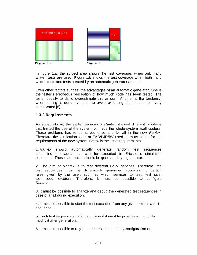
In figure 1.a, the striped area shows the test coverage, when only hand written tests are used. Figure 1.b shows the test coverage when both hand written tests and tests created by an automatic generator are used. Even other factors suggest the advantages of an automatic generator. One is the tester’s erroneous perception of how much code has been tested. The tester usually tends to overestimate this amount. Another is the tendency, when testing is done by hand, to avoid executing tests that seem very complicated [6].
1.3.2 Requirements As stated above, the earlier versions of Rantex showed different problems that limited the use of the system, or made the whole system itself useless. These problems had to be solved once and for all in the new Rantex. Therefore the verification team at EAB/PJR/BV used them as bases for the requirements of the new system. Below is the list of requirements: 1. Rantex should automatically generate random test sequences containing messages that can be executed in Ericsson's simulation equipment. These sequences should be generated by a generator. 2. The aim of Rantex is to test different GSM services. Therefore, the test sequences must be dynamically generated according to certain rules given by the user, such as which services to test, test size, test seed, etcetera. Therefore, it must be possible to configure Rantex. 3. It must be possible to analyze and debug the generated test sequences in case of a fail during execution. 4. It must be possible to start the test execution from any given point in a test sequence. 5. Each test sequence should be a file and it must be possible to manually modify it after generation. 6. It must be possible to regenerate a test sequence by configuration of
Figure 1.a
Untested Area (UA)
Figure 1.b
UA
4(42)
Rantex. 7. Rantex should log all actions so that Rantex itself can be debugged easily and its work process should be easy to analyze. 8. The memory complexity of Rantex must be linear (proportional to the test size), not exponential. Specifically, the test generator must be optimized for memory consumption. 9. It is important that new services can be added in the future in a flexible and effective way. It is also of great importance that the software is useful even in case of new protocols, new hardware or new standards in the future. 10. Since testing often requires a long execution time, the part that executes the tests must be optimized for speed. 11. Rantex must apply with Ericsson's standard procedures for developing products regarding documentation standard, code standard, release handling, version handling.
1.3.3 Services to implement Besides the technical requirements, a list of GSM services to implement was also made. The services to implement were different channel combinations used for carrying services as for example speech, signaling, data and high-speed data. Each channel combination behaves in a specific manner from the resources point of view, demanding different amounts of bandwidth. The implementation of the channel combinations has to respect the different dependency relations that can arise within the same channel’s components or between two different channels. For more details about the different channel combinations, see section 4.2. 1.4 Equipment
The equipment at disposal during the developing Rantex was the following:
• Two PCs with Microsoft Windows
• Two Sun computers with Unix Solaris
• One test site in an Ericsson laboratory
5(42)
2 Theory 2.1 Testing software During the course of years, software products have gradually evolved from being addressed to an average user with a wide knowledge of computer and programming, to a new one with a poor or mediocre education in the field. The results of this development are products that everybody can use, or at least, products with basic functionality that do not call for any kind of specific knowledge [6]. Moreover, the new users require an always growing number of functionality and that the system should work together with other products. A direct effect of all these requirements is a growing number of code lines for the new products launched on the market with unavoidable consequences on the development cycle and in particular, the testing phase. 2.2 Mistake, failure or fault? A defect is an error in the system. The Institute of Electrical and Electronics Engineer’s (IEEE) Standard Glossary of Software Terminology [14] has classified different types of causes behind possible malfunctions of the software. The malfunction can be a consequence of a:
- mistake is a human action that produces an incorrect result. For example an incorrect action on the part of a programmer, in interpreting the system’s requirements, or the operator, in using the software;
- failure is an incorrect result. For example, a computed result of 12 when the correct result is 10, that is the inability of a system to perform its required functions within specified performance requirements;
- fault is an incorrect step, process or data definition. For example, an incorrect instruction in a computer program. In common usage the terms “error” or “bug” are used to express this meaning [14].
2.3 Testing and debugging Testing software products means verifying that it behaves as stated in the product specification. Testing is more than just debugging. The purpose of testing can be quality assurance, verification and validation, or reliability estimation. [8] The testing includes two different aspects. One is the verification of a correct implementation of all the requirements according to the specification. The other is the identification and elimination of all kinds of defects present in the source code. The first aspect consists of verifying the system as a whole and analyzing its behavior, performance, reliability, security etc. The second aspect focuses on verifying that each portion of the source code is correct, i.e. analyzing the behavior of different classes or functions of the system.

6(42)
Sometimes the word testing is used both in the case where actual testing is taking place and when the operation in course is that of debugging. In fact, the testing is the action of executing a component or a whole system under specified conditions, where the results are observed or recorded. The objective when debugging is to correct the faults in the code [14]. The debugging uses the results of the testing phase to find the faults in the system that needs to be eliminated. 2.4 Testing Software bugs will always exist in any software system of moderate size. Partly because of the limited ability for humans to manage complexity and partly because in any complex system, design defects can never be completely eliminated [8]. When looking for defaults in a physical system, it is often possible to decide if it will behave as expected simply by finding the actual physical limits of it, e.g. the maximum weight, power, heat or bending angle the system will tolerate. Once these limits have been stated, they can be used to formulate restrictions within which the user is assured the system will work. The limits in a software system are its conceivable inputs, both those allowed and those that are not. A correct result with certain inputs will never imply that the system will behave as expected with other inputs. The same thing concerns the number of test executed; if n number of tests end with a positive outcome, it is impossible to have the certainty that the test number n+1 will do the same. Moreover testing a software product does not only include verifying that the product itself works correctly, but also that it works together with the other modules with which it will cooperate. The certainty of complete correctness will only be obtained by testing the system with every possible value and sequence of inputs, in every possible state the system under test can be found [3]. This process, called Exhaustive testing is theoretically possible but would be unfeasible due to the amount of time (= money) a program, even one with a moderate complexity, would require. New testimonies about the complexity of testing can be found almost every day in the press reporting about new problems with different software products. In general, these cases are not examples of products brought out without first be tested, but simply evidences of how difficult it is to deliver a system free from errors. Worth mentioning is that not only commercial products are afflicted with errors, there are also several examples of function failure in systems whose software costs usually are much higher than that for commercial products, as in the case for applications used for military purposes or in space programs.

7(42)
2.5 Failures
2.5.1 Ariane 5 After spending $ 7 billion and 10 years developing the Ariane 5 rocket, in June 1996, the European Space Agency was ready to project itself and Europe into a prominent position in the field of commercial space business. 39 seconds after take off, a self-destruct mechanism destroyed the rocket because of an alternation of course. The steering system, controlled by an on-board computer, made a course correction, compensating for a wrong turn that in fact had not taken place. This fateful decision from the steering computer resulted from data coming from the inertial guidance system that uses gyroscope and accelerometers to track motion. As the steering system was receiving this incorrect data, the guidance system had shut down and the received data was not flight data, but numbers indicating a diagnostic error message. The guidance system was shut down when its own computer tried to convert a number, indicating the sideways velocity of the rocket, from a 64-bit format to a 16-bit format. Being too big, the number caused an overflow error in both the primary guidance system and the redundant backup unit. The software used in the Ariane 5 was the same, supposedly very reliable, used for the Ariane 4 rocket. The Ariane 5 was faster than Ariane 4 but in the case of this particular velocity, the programmers decided that it was unnecessary to protect the data conversion with some lines of code to catch an eventual error or to allocate more memory for the variable, assuming that the velocity value never could be big enough to create problems [11].
2.5.2 MIM-104 Patriot On February 25, 1991, during the operation Desert Storm, an Iraqi Scud missile avoided interception and killed 28 soldiers from the US Army. An investigation revealed that the failed intercept had been caused by a software error in the system’s clock. The error was a result of several arithmetical operations that systematically led to a periodic value, which was subsequently truncated to 24 bit, generating an error that grew with time. The system that should have intercepted that particular missile had been in function for 100 hours causing the drifting of the internal clock by one third of a second, which for a fast moving target, as a Scud missile, was equivalent to a position error of 600 meters. Once the system had detected the Scud and predicted where to find it next, because of the time error it looked in the wrong direction and found no missile to intercept. The initial detection was then rejected as false alarm and the missile to intercept removed from the system [12].

8(42)
2.5.3 Therac-25 The Therac-25 was a radiation therapy machine involved with the death of at least five patients between 1983 and 1987. The deaths depended on an error in the software that enabled the machine to give the patients massive overdoses of radiations. The software did not detect that the machine gave radiation in certain circumstances and could therefore not stop it from doing so. There were several causes behind this malfunction. The most significant was the reused software from older models. These models had hardware interlocks that masked their software defects. The problem was that the machine never notified the user that the software was malfunctioning. The new model did not have any kind of interlocks and still the software could not verify if the sensors were working correctly. Aside from the problems described, the software gave rise to an occasionally arithmetic overflow that made the software bypass the safety checks [13]. 2.6 Testing techniques There are different techniques to test a system, each suggesting a subset of entries that will allow a discrete test of a system or part of it. It is necessary to keep in mind however, that these techniques will never be a guarantee that the system will function with all possible other entries that have not been tested. A system that behaves correctly when tested with certain inputs can indicate either that the system is correct or that the used test case is inadequate to highlight the errors present in the system [6]. The techniques can usually be grouped under two categories: black-box testing or white-box testing.
2.6.1 Black-box testing Black-box or functional testing is carried out by deriving the test data from the specified functional requirements and observe if the system, or subsystem, behaves or responds as expected. The program structure, or source code, is not taken into consideration. The testing can be seen as input/output driven or requirement based. During the test, the system is seen as a black-box, the only visible factors are the inputs, the outputs and the specification. Not knowing the details of how the system has been implemented, it is not possible to put a specific algorithm or the implementation under test. The inputs in the test cases are derived from the specification. The success of a test is determined by looking at the outputs generated by the inputs. The outputs are compared against specification to validate the correctness. This means that the greater the number of test cases, the higher the number of problems that will be found, but as stated before testing all possible

9(42)
combinations of inputs for a system is unfeasible for most programs. Combinatorial explosion is the major hindrance in functional testing. Other possible problems arise, in many cases from the specification that can be incorrect, incomplete, or ambiguous [8]. However, the research in black-box testing focuses today on finding a methodology that maximizes the efficiency of testing with minimum cost; this is often done by increasing the number of test cases. It is not possible to exhaustively test all possible inputs, however by using a technique called Domain testing, it is possible to exhaustively test a subset of the input space. When using the Domain testing technique the input space is divided into regions, or partitions. Partition testing suggests a logical basis on which partitions and values from each partition can be selected [3]. The values contained in a partition are seen as belonging to an equivalent class. This means that if a single test value from a specific partition passes (or not), all other values in the same partition are expected to behave in the same manner [3]. By testing one or more of these values, often boundary values are chosen, the domain is exhaustively tested and covered. For the Domain testing to be effective, a deep knowledge of the software structure is needed in order to create relevant partitions [8].
2.6.2 White-box testing The white-box testing technique consists of analyzing the behavior of the system and having the possibility to observe the implementation. This possibility enables the tester to perform a deeper verification work compared with the black-box technique [6]. In general, this verification is performed through two categories of tests called respectively formal verification and informal testing. The formal verification implies that the correctness of a segment of the source code is proved mathematically [6]. The first to suggest that a computer program could be seen as a series of mathematical relationships was Dijkstra in the early 1960s [4]. The verification of the system is made by formal proof on an abstract mathematical model of the system [17]. This kind of approach requires a translation of both the specifications and the source code in a formal language created by applying techniques loaned from both mathematics and logic [7]. This kind of formal language eliminates the ambiguities in the specifications, allowing to exactly specify how the system is supposed to behave, and make it possible to analyze the algorithms in the system through mathematical rules. If this procedure is carried out correctly, i.e. if the translation is correct, the formal test will guarantee that the tested code segment will behave correctly. The drawbacks with formal testing is the time and specific knowledge the translation into formal language will require, since the translation is made by hand and the knowledge is not of the kind the average programmer holds. All this makes the formal verification a very expensive form of testing, and that is why the process is only applicable to fragments of the source code. It is rare that this kind of testing is used for regular commercial systems and when this happens, it is usually done to test a small critical part of code.
10(42)
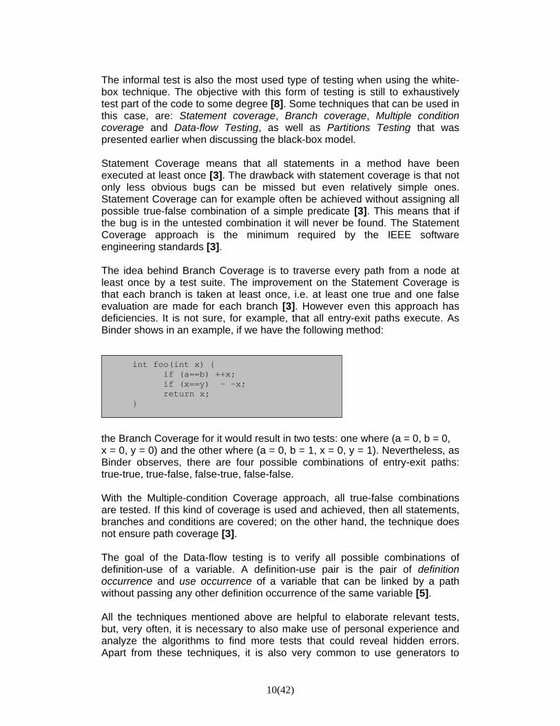
The informal test is also the most used type of testing when using the white-box technique. The objective with this form of testing is still to exhaustively test part of the code to some degree [8]. Some techniques that can be used in this case, are: Statement coverage, Branch coverage, Multiple condition coverage and Data-flow Testing, as well as Partitions Testing that was presented earlier when discussing the black-box model. Statement Coverage means that all statements in a method have been executed at least once [3]. The drawback with statement coverage is that not only less obvious bugs can be missed but even relatively simple ones. Statement Coverage can for example often be achieved without assigning all possible true-false combination of a simple predicate [3]. This means that if the bug is in the untested combination it will never be found. The Statement Coverage approach is the minimum required by the IEEE software engineering standards [3]. The idea behind Branch Coverage is to traverse every path from a node at least once by a test suite. The improvement on the Statement Coverage is that each branch is taken at least once, i.e. at least one true and one false evaluation are made for each branch [3]. However even this approach has deficiencies. It is not sure, for example, that all entry-exit paths execute. As Binder shows in an example, if we have the following method:
int foo(int x) { if (a==b) ++x; if (x==y) - -x; return x;
} the Branch Coverage for it would result in two tests: one where (a = 0, b = 0, x = 0, y = 0) and the other where (a = 0, b = 1, x = 0, y = 1). Nevertheless, as Binder observes, there are four possible combinations of entry-exit paths: true-true, true-false, false-true, false-false. With the Multiple-condition Coverage approach, all true-false combinations are tested. If this kind of coverage is used and achieved, then all statements, branches and conditions are covered; on the other hand, the technique does not ensure path coverage [3]. The goal of the Data-flow testing is to verify all possible combinations of definition-use of a variable. A definition-use pair is the pair of definition occurrence and use occurrence of a variable that can be linked by a path without passing any other definition occurrence of the same variable [5]. All the techniques mentioned above are helpful to elaborate relevant tests, but, very often, it is necessary to also make use of personal experience and analyze the algorithms to find more tests that could reveal hidden errors. Apart from these techniques, it is also very common to use generators to
11(42)
create test sequences automatically, based on parameters given by the user. These generators are of great help when testing complex systems, and writing test cases by hand would be too demanding. 2.7 Other verification techniques Black-box and white-box testing are not only used with the techniques described above, where the main purpose is to verify the source code belonging to individual software modules. The black-box approach is often used also to verify that the requirements are implemented in accordance with the specifications. The techniques used for the purpose are usually: integration testing, system testing and regression testing. To verify that the source code is correct overall, the white-box approach is often used with techniques as: unit testing, integration testing and regression testing.
2.7.1 Unit testing A unit test has as scope a limited part of the source code. The part can contain just one class, different but related classes or an executable binary file [3]. The goal is to prove that the individual parts behave correctly. The procedure includes test cases, for all functions and methods, that can later be used to localize changes that cause a regression [20]. Unit tests can also be seen as a detailed description of how the specific module or segment of code is supposed to behave and can therefore be used by clients and other developers to learn how to use the module. Since unit testing is supposed to only test the functionality of the tested unit, it will not be of help in the case of integration errors or any other kind of malfunction at a system-wide level. Further, as stated before, it is never easy to test all inputs to a system, or as in this case the single program unit, may receive when in use and since it is impossible for most programs to test all possible inputs, even unit test can only be used to find errors and not to prove the absence of errors.
2.7.2 Regression testing Regression test is the kind of testing done each time source code is added or changed. This test is made to make sure that the changes do not entail the introduction of new errors or the reintroduction of errors that have already been resolved, i.e. that the changes do not cause a regression in the system. Usually, regression testing techniques include re-running previously successfully run tests to see if they still pass.
12(42)
It has been found over the years, that as software is developed, the re-emergence of fault is very common. In certain cases, this is caused by earlier (weak) fixes that, after some changes to the source code, not longer work. To avoid these kind of errors, it is good practice that when a fault is found and fixed, a test that reveals it, is regularly retested after having made changes to the program [19]. Regression testing is often automated. Manual regression testing can be very effective during the first phases of the testing, when single components or systems are analyzed, but is not an option for repeatable and consistent regression testing [3].
2.7.3 Integration testing The intent with integration testing is to find component faults that cause intercomponent failures [3]. This kind of test is executed periodically to ascertain that new components and code added to the system does not compromise the functionalities already working at that time. An integration test can include a complete system or a subsystem of software and hardware units that needs to cooperate to meet some requirement [3]. The modules that serve as input for integration testing and have already passed unit testing, are grouped together and tested according to a test plan. The result of integration testing is an integrated system ready for system testing [21].
2.7.4 System testing The system testing is concentrated on verifying the complete product in view of a release to the costumer and is used to evaluate the product’s fulfillment with the requirements. During the system testing, not only the design is tested but also the behavior of the system to see if it corresponds to what the customer expects from it. Alpha testing and Beta testing are sub-categories of system testing [18]. Alpha testing is carried out, before a release, and usually within the company that produces the software. When the product has passed the Alpha testing, it can be released to a part of or to all clients, with the remark that its quality cannot be guaranteed. Such a version of the product is called a Beta version. The thought behind the release of a Beta version is that eventual users of the final product can use the software in realistic situations and supply the company with information of malfunctions they have come across. This kind of test, made by the users and free for the developers, is the Beta testing. The company continues the release of new Beta versions until the point they feel confident enough to release an official version [16].
13(42)
2.8 Performance, reliability and security The aim for the techniques discussed until this point has been to verify the correctness of the software, i.e. to see that all functionalities works properly. There are however, other testing methods created to reveal issues related to other characteristics, e.g. performance, usability, reliability, security, compatibility et cetera, some of which will be reviewed more in detail below. Apart from very few of them, it can be hard to think out and/or perform tests capable of measuring the characteristics listed above, either due to their nature, as in the case for usability testing, or even in the case where some tests need to be performed by hand, as in the case for security testing that can only be automated in part [6].
2.8.1 Performance testing When carrying out performance testing, the ‘errors’ to locate are those that entail degradation in the system performance. Performance evaluation of a software system takes into account things such as resource usage or input-output time. Other factors that need to be included in the evaluation are network bandwidth requirements, CPU cycles, disk space and memory usage [8]. To be able to deliver reliable results, performance testing must be preceded by specific objectives that set limits to the software execution time and resource use under specific circumstances of use. These limitations can then be written in the system performance requirements, stated in terms of response time, throughput, or utilization [3]. Performance specifications should be written at the same time the requirements are discussed and before the developers start with the design work, but in many cases this does not happen. The expected performances are then implicit, e.g. it should take an acceptable amount of time to get an output from the system or that the system is adequate for the available resources [22]. When requirements are stated, they are often either set for average performance or for worst-case performance, depending on which kind of system is being investigated, a data-processing system or a mission-critical system [3]. The testing is often done by finding a workload that can simulate the kind of usage the system will be exposed to. Apart from finding performance weaknesses, performance testing can even be used to compare different systems from the performance point of view. During the tests, tools such as profilers are used to find the segments that affect the performance negatively or to set boundaries for acceptable response time [22]. As a program runs, a profiler measures the behavior of it, particularly the frequency and duration of function calls. The output is a stream of recorded events or a statistical summary of the events observed [23].

14(42)
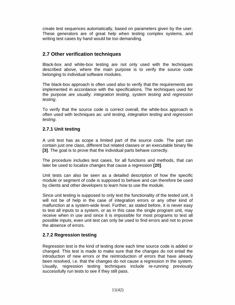
Figure 2: Typical reliability growth curve for software.(Source [10])
2.8.2 Reliability testing Software reliability is defined by the IEEE as “the probability that software will not cause the failure of a system for a specific time under specific conditions” [14]. If the goal of correctness testing is to achieve reliability, the objective with reliability testing is to evaluate it. An often used measure for reliability, together with software execution time, is often used the number of software faults per thousand lines of code [24]. The idea behind this measure is that as the number of faults decreases the reliability of the software increases. Even software reliability should start very early in the development of the system, starting with single units and proceeding up to the complete system. When testing at system level, the measure, used to estimate reliability is the mean time between failures [24]. The benefits acquired through reliability testing are several. Apart from offering a tool for estimating reliability, it can for example help improve the software in a more practical manner. A problem with correctness testing can be that in the case where the majority of the found faults would be of the kind that occurs very rarely in the actual use of the system, repairing them would not improve the final software substantially. Reliability testing will instead show those faults that are most likely to cause failures during execution [7]. One method to achieve software reliability is the Software Reliability Engineering (SRE). The method is based on four steps that, however, are not performed as isolated events during the development, but are often integrated in other phases. The steps are: determine reliability goals, something that is part of the requirement definition process; develop operational profile, which take place at the same time as software design and coding; plan and execute tests and finally, use test results as basis for decision making, which is part of the entire test plan. The customer’s expectations of acceptable reliability are stated in the reliability goals. It is important, in this phase, to find a way to describe these expectations in a quantifiable manner. For example, the quantity of errors accepted for a specific amount of actions [7]. The operational profile is supposed to reflect the actual usage of the system, to allow the reliability prediction to be as realistic as possible. The elements in the profile are assessed through their probability of occurrence or importance. Using the operational profile as a guide for the system testing ensures that the system is best

15(42)
tested for most-used and most critical operations [7]. Test cases are created after probability and critical factors to ensure that the functions they depend on are even the most tested. The use of an estimation model as a typical reliability curve such as the one shown in figure 2, can be used, during the tests to analyze the data, estimate the level of reliability the system has achieved and predict future reliability [8]. The test time in the figure represents iterative tests. After each test iteration, the system is cleared of faults and the updated version is used for next iteration. The failure intensity is the amount of failures during testing [7]. Based on the estimation, it is then possible to decide how to proceed. The developers can decide to continue with the testing or to release the software and the user can decide if the product can be accepted and ready to be used [8].
2.8.3 Security testing The objective behind security testing is to find vulnerabilities in the system that can be exploited by an attacker and to evaluate the security measures included in the software [8]. Vulnerabilities can be faults at the implementation level or flaws at the design level. Risk analysis, especially at the design level, can be helpful in identifying security problems and their impact [9]. With the identification of risks in the software, it is then possible to create tests based on them. Security testing should consist of two phases, one focused on testing security mechanisms in the software to validate their correct behavior, and one with the aim of simulating malicious attacks. That is why security testing is partially performed by automation together with regular developers, to perform functional testing, and partially involves specialists in the field and cooperating hackers that try to perforate the system [3]. 2.9 Fuzz testing Besides all the testing techniques discussed above, where a lot of work is put into the design of test cases, there is the fuzz testing technique. This technique’s characteristic is that the inputs of the system under test, are generated randomly. This approach allows an extremely simple test design and makes the cost of generating tests relatively low. Fuzz testing should not be seen as a substitute for other formal methods, because it is not. The technique should be used rather as a complement to other techniques. The major benefit that fuzzy testing can entail, besides the low costs, is that the random nature can expose unusual defects that testers could have overlooked or not taken into account during the test design phase [25].

16(42)
2.10 Testing automation Automation is a solution to hold down costs and time for testing. The only disadvantage with software testing tools could be the fact that there does not exist a tool that can be used with different systems. To be able to automate the testing process, there is always the need for an oracle to decide if the system behaves as expected. The oracle is obtained from the system’s specifications and therefore linked to that particular system. Still, to be effective and repeatable, the testing has to be automated. Once developed, the testing software can, depending on how much resource is invested in it, be capable creating test inputs and receiving results, run test suites without manual intervention and evaluate if the test passes or not. How much of the testing that should be automated depends on factors such as for example testing goals, budget and kind of application that is developed, but in most cases is important that some testing is automated in order to be efficient and repeatable [3]. The main advantages Binder sees with automated testing are, among others:
• The possibility to rerun the exact same inputs that earlier have revealed a bug, i.e. a quick verification of fixed code.
• Developing testing software is not cheap and in many cases not easy, but the effort in time and money will be recovered in form of increased productivity and avoided costs associated with the release of a buggy software.
• Since the testers gain time with automation, there is the possibility to spend more time to design tests to attain greater coverage.
• Manual testing implies human errors. • Regression testing, compatibility testing, performance testing, together
with other testing forms, need automation to be sure that the same testing is done when the software is updated.
• Long and complex tests, made up of thousands of test messages are often impracticable to manage and repeat by hand, and need automation.
• Automated comparison is the only repeatable and efficient way to evaluate a large quantity of output.
Even if some automated testing is essential in most cases, there are other situations where manual testing can be more appropriate. Binder lists some examples:
• A tester, with deep knowledge of the software under test, can be very useful in creating tests, based often on a “feel” or suggestion by some response of the system under certain circumstances.
• Automation is expensive. If there is not a need to repeat tests, then it is sufficient to just run the system.
17(42)
• To be able to repeat testing, it is crucial to maintain test cases and test suites. The cost for this maintenance can become very high if the requirements and implementation of the system change frequently. If the test automation is not maintained, the rerun will not be possible.
Ideal would be to find the right balance between manual and automated testing. A combination of the two is often the way chosen in most cases. 2.11 When to stop testing? As stated before, demonstrating the absence of errors is not a trivial matter and testing is not capable of doing it. The question is then when it is safe to stop testing. The time dedicated to the activity of testing is in reality driven by profit models and is a balance between budget, time and quality. In the worst cases, when one of the mentioned resources, time, budget, or test-cases, are exhausted the testing is stopped. In the best cases, the approach is to stop when either the reliability reaches the definite requirements, or when the improvements, acquired through testing, no longer justify the costs [8]. Usually the considerations to make before stop testing are, according to Sillitti, two:
1. The tester could assume that the errors are evenly spread in the source code, but this is not the case in general. Several researches shows that 80% of the errors can usually be found in 20% of the code and further, 50% of them is contained in 5% of the code. The advantage with this information is that if the tester is capable to find these areas of code, where the errors are more frequent, a test concentrated on them would result in a substantial improvement of the code in relatively short time and at low cost [6].
2. The number of errors in a system depends on the chosen process of development. On the average the number is between one and 25 each thousand rows of code. With this information it is possible to make an estimate of the total number of errors present in the system, try to find and fix a bigger part of them and then decide when the system has been tested enough [6].

18(42)
OutputTest
sequence
Log
Configuration file
Generator
Structurelibrary
Resource Control
Runner
...
...
Retriever
Status Loader
Message Decoder
Central System Extended System
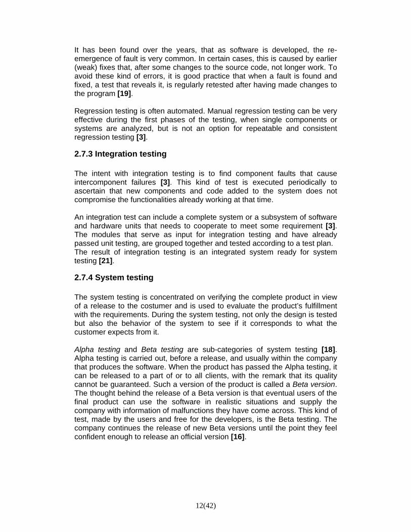
Figure 3. Rantex System
3 Implementation 3.1 System overview Rantex has been built as two systems working together. There is the Central System and the Extended System. The thought behind this choice is to have a part, in this case the Central System, which alone is able to perform Rantex’ s main task: to generate and execute tests. All other additional modules that are not necessary for the test generation and execution are instead supposed to be placed in the Extended System. Rantex is composed of text files and program files. The languages used in these files are Java, C++ and Extrava, the language that was developed explicit for Rantex during the course of the project (see section 3.2 Extrava).
The files are grouped into modules. The choice of a design with specialized modules is based on the requirement of a system that should be easy to update and maintain, together with the possibility of easily adding new services in the future.
Figure 3, shows all the modules that together constitute the Rantex system. The arrows represent the data flow in the system. This thesis will focus on the modules for Resource Control, Runner and on the Extended System.
Rantex System
19(42)
3.2 Extrava One of the problems in the developing of Rantex’ s earlier versions was the syntax used to declare the structure behind the messages describing single channel combinations. Each message is composed of several fields. Each of these fields can contain several variables, to which different values can be allocated. Which value is allocated depends, in many cases, on some earlier allocated value in a different field. Even whether certain fields will be included in a message or not, can depend on what is stated in some other field of the same message. Moreover dependency can also exist between different messages. Since the task with this Rantex was to create a completely new system, the question was to come up with a syntax that was easy for the user to use and powerful enough to simply describe the different channel combinations with the relative dependencies. The principal idea behind Rantex was to have specific classes, called Structure files or Structure classes, each describing a channel combination. In a Structure file all allowed values and dependencies are described by the user. To generate a message to send to the simulators, Rantex will read a Structure file and try to generate a correct command activating the channel combination described in it. During the search for a language that could offer a simple writing of the Structure files, the idea of developing a completely new language seemed gradually to be the most appropriate for the chosen design of Rantex. At the end, after having considered the advantages and disadvantages of creating a new language instead of using a more well known and, above all, more tested one, the chosen path was that of developing a new language. This language was named Extrava. The advantages that a custom-made language should result in seemed obvious. By being specifically developed for Rantex, the language would only include the needed functionality. Moreover, since the development was from scratch, the syntax could be structured to be as user friendly as possible. Furthermore, no external software would be needed to compile the files written in Extrava, and this should result in faster generation of tests and compiling. Not to mention that since Extrava was an integral part of the system the compilation would be transparent for the user. Of course, there would also be disadvantages. The two major ones, from the user’s point of view, would be that the user had to learn a new language and syntax, and that the language had not been tested by actual users which could result, in future, in some functionality problem that may not have been taken into consideration during the development. From the developers’ point of view, the major problem would, of course, be the required amount of time and resources the development of a new language, interpreter and compiler that would imply. Time that could instead be spent on increasing the functionality of the final product.

20(42)
The alternatives to Extrava would either be an OO-language, such as C++ or Java, or some functional or logical language. The advantage of an OO-language would be that most users at the company would probably be already familiar with it and that it would not be necessary to develop new debuggers or related tools. The problems, or disadvantages, an OO-language would imply, on the other hand, would be things such as external software, needed for example to compile the files, which would require more time in the execution process, larger classes than those written in Extrava and the need for implementing an interface between Rantex and the Structure and Configuration files. When it comes to functional or logical languages, as Haskell and Prolog, one problem is that they are not very common among standard users, which would imply that they need to learn a new language anyway; moreover these languages are usually very slow compared to other types of languages. Apart from this, the use of such a language would have resulted in a more difficult implementation of the interface to Rantex. 3.3 Central System As said before, the modules in Rantex can be made of text files or program files. A short overview of what the different modules contain and what their main task is will follow here. Before starting with the modules, a presentation of another type of text file is needed, the Structure file.
3.3.1 Structure file For Rantex to create a test sequence that will be valid in the simulated environment, it is necessary to specify what the different messages, which will represent different GSM services in the sequence to test, will include. The simulator interprets and returns messages written in hexadecimal figures. Each GSM service has a specific structure composed of several segments that can have different values at different times, depending on what is tested. In interpreting these values, the simulator can determine if the message is valid or not. A Structure file describes the structure of the message to generate. The file is fragmented in fields, reproducing the structure of the message. When a message is created each fragment gets a value, either randomized from those allowed for that segment or determined by some dependency relationship, as defined in the file. Each service that can be tested has its own Structure file that describes its structure. The thought behind the development of separated Structure files, where each service is defined, was to develop a new syntax for Rantex that could offer the user a quick overview of, for example, allowed values or

21(42)
dependencies between different fields within a message, and reduce the complexity of expression to facilitate eventual debugging operations. Structure files are implemented in Extrava and use both identifiers, as general and variables in the example below, and reserved keywords, as var and where.
structure name { general: messagetype = RSL;
messagestructure = {messageType, channelNumber, channelMode, …
encryptionInformation}; expectedanswer = {messageDiscriminator,
channelNumber, …};
variables: var channel, sub, timeslot, ….
message:
messageType = 0x41; channelNumber = {1, channel} where { sub = 0 | 1, channel = 8 * sub + timeslot, timeslot = 0:7, } channelMode = {6, 4, 0, indicator, rate, algorithm}
where { … algorithm = … …; }
encryptionInformation = {7, length, encryption, key} where {
… }
resources: ResourceControl::occupySlot(FULL_RATE, timeslot)
onlyif rate = 3; …
dependencies: allow algorithm = 2 onlyif indicator = 2; allow rate = 3 onlyif indicator = 4; …
}
Example of a Structure file. Each channel combination is defined trough a file like this.

22(42)
3.3.2 Module overview 3.3.2.1 Text modules Structure library A Structure library is a file where the path of all Structure files needed in the test to generate, is defined. Each row of the library includes the name of the Structure file, which does not need to be equal to the name of the actual file, a probability value and a path to the Structure file to read. The probability value is a positive integer used to tell Rantex with what probability a message from that Structure file should be generated, relative to the other messages defined in the library, a technique called weighted mean values. A Structure library is written in Extrava Configuration file In the Configuration file, as the name suggests, the user configures Rantex and the variables that will affect the generation of the test. Test properties such as for example test size, test kind, which Structure library to read, and seed for generation, are defined. A Configuration file is written in Extrava.
LibraryX{ …
ChannelCombinationX 5 "lib\ChannelCombX.struct"; … }
An example of Structure Library.
configuration Name { general:
// paths structureLibrary = "structurelibrary.lib"; sequenceOutput = "sequences/test.tsq"; // general options seed = name; testSize = XXX;
…. }
Example of Configuration file.

23(42)
Test Sequence A test sequence is the product that the Generator module will create when the generation process is terminated. The sequence contains messages in hexadecimal form and labels, which can be interpreted by the Runner as commands to for example activation or deactivation of a service.
Log To make debugging easier, it is possible for the user to log the work behind each single message that is included in the test sequence. In the Configuration file, it is possible for the user to decide not only what kind of information to log, but even how much of the work done should be logged. Seven fields related to the Generator’s generation process can be logged. These are: dependencies, arithmetic, resources, printing resources, variables, errors and warnings, and general messages about the generation. The field printing resources prints the resources status to the screen, very useful for the user to follow in real time the resources status after each message. Dependencies, arithmetic, resources and variables fields log the work done by the Generator when trying to create a message from a Structure file. Each time a variable is assigned a value, a dependency is tested, an arithmetic operation performed, or a resource allocated or released, the action will be logged if the user has chosen to do so. As stated, not only is it possible to choose what to log, but even how much should be logged. This is done by assigning each field a value between zero and three. Zero means that nothing that the Generator does, that is related to that field, will be logged, and three means that everything the Generator does or tries to do, during the generation, that is related to that field will be logged. The resulting log can be attached to the test sequence and printed to the screen.
:label1 w trx1 rsl 0x8 0x2e 0x1 0x8 0x2b 0x3a 0xa r trx1 rsl 0x8 0x33 0x1 0x8 :label1 w trx1 rsl 0x4 0x17 0x7 0x2 0x5c 0xa 0x7 0x32 0x12 0x4 r trx1 rsl 0x1 0x22 0x4 0x7 0x12
Example of a Test Sequence.

24(42)
Output The Output is the result of the execution performed by the Runner. The output is generated at the same time the execution of the test sequence is taking place, to allow the user to follow the process. 3.3.3.2 Program modules Each module in Rantex can be seen as a package including several classes. Generator The Generator can be seen as the heart of the Central System. The classes included in this module are responsible for the generation of a valid test sequence. The Generator does this by validating and interpreting Configuration files and Structure files, and through constant communication with the module for resource control. The validation and interpretation process leads to a generation of data structures that will constitute the grounds on which the test sequence is built. The classes in the Generator are written in Java. More details on how the module works can be found in the thesis report written by Sam Mottaghi [1]. Resource Control This module’s task is to control that there are enough resources available for the services that the Generator tries to add to the test sequence, and that the rules existing within a service, i.e. a channel combination, and between different services are followed. All the classes in the module Resource Control are written in Java. Runner Due to the requirement of fast execution of a test sequence, the Runner module has been implemented in C++. The Runner takes a test sequence as input and sends it, after conversion into interpretable data, to the simulator. The sent messages and the relative answer received from the simulator are then continuously printed to the screen.
3.3.4 Dataflow The arrows in figure 2, symbolize the data flow in the process of generation and execution of a test sequence. What the system must have available for starting a generation is a valid Configuration file, where we have specified the test to generate, and a

25(42)
Structure library, including all the Structure files describing the services we want to test. What will happen when Rantex is started is that the Generator will read and validate the Configuration files. If this step goes through, i.e. if the Configuration file is valid, the Generator is configured as defined in the Configuration file. When the Generator is configured, it will read the Structure library and compile the Structure files included in it. If all Structure files are valid, the Generator will then create data structures from them and can, after that, start generating messages that will be included in the test sequence. During the generation process, the Generator communicates constantly with the module for resource control. Each time a message is created, and before it is added to the test sequence, the Resource Control module will test if there are enough resources, and that the values in the message do not violate any rules within different fields in the same message or between different messages. When the process is terminated, the created sequence can be interpreted by the Runner, which sends the messages in the test sequence to the simulator through the serial port. During the execution, the status of it will be printed to the screen continuously. In case of failure during the generation process, this will be aborted and a message about it given to the user. If the failure occurs during the execution, a failure message will be printed in the output and Rantex will either stop the process or continue depending on how the user has configured the Configuration file.

26(42)
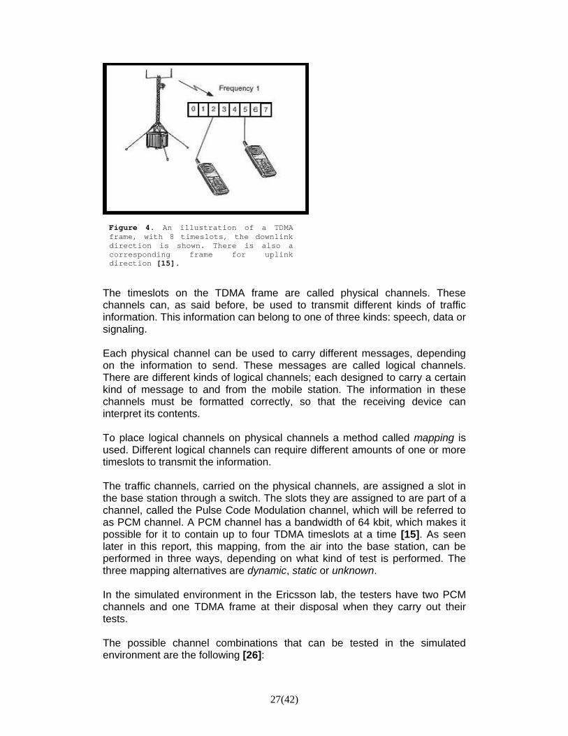
4 The Module for Resource Control The purpose with a module for resource control is to simulate the status of the resources present in the simulated environment. During the time in which the Generator tries to generate messages, it communicates with the module responsible for the resource control. Each time the Generator creates a message, before adding it to the test sequence, it needs to know if there will be sufficient resources in the simulator, and if the channel combination in the message can be allocated to the chosen resources without breaking any rule, to avoid to get a fail during the execution. In the module for resource control, all the physical resources, used during a communication between a mobile station and a base station, are simulated. The Resource Control’s main task is to control the services and channels that will be used during the execution and report if collisions or erroneous behaviors are taking place. When the Resource Control sends a negative answer to the Generator, this will discard the message that breaks against the rules and generate a new one. When the message sent by the Generator does not break any rule or does not try to occupy unavailable resources, the Resource Control sets aside the resources needed by the channel combination in the message, or releases resources if the message is a request of channel release. To better understand the kind of resources the module has to simulate, a short presentation of the data flow taking place in the simulated environment will follow. This presentation has not the ambition to cover all the processes taking place between a mobile station and a base station, the only purpose with it is to present the parts simulated in the module for resource control. 4.1 The simulated environment To receive and transmit signals, e.g. speech or data, most digital cellular system use a technique called Time Division Multiple Access, TDMA. TDMA allows several channels, i.e. services, in one common frequency band, a carrier. Each channel uses that carrier at a designated time division, a timeslot. A TDMA frame is the GSM air interface’s timeframe, comprising eight timeslots, each containing up to 16 kbit. This makes it possible for each GSM radio carrier to carry up to, for example, eighth calls [15].
27(42)
The timeslots on the TDMA frame are called physical channels. These channels can, as said before, be used to transmit different kinds of traffic information. This information can belong to one of three kinds: speech, data or signaling. Each physical channel can be used to carry different messages, depending on the information to send. These messages are called logical channels. There are different kinds of logical channels; each designed to carry a certain kind of message to and from the mobile station. The information in these channels must be formatted correctly, so that the receiving device can interpret its contents. To place logical channels on physical channels a method called mapping is used. Different logical channels can require different amounts of one or more timeslots to transmit the information. The traffic channels, carried on the physical channels, are assigned a slot in the base station through a switch. The slots they are assigned to are part of a channel, called the Pulse Code Modulation channel, which will be referred to as PCM channel. A PCM channel has a bandwidth of 64 kbit, which makes it possible for it to contain up to four TDMA timeslots at a time [15]. As seen later in this report, this mapping, from the air into the base station, can be performed in three ways, depending on what kind of test is performed. The three mapping alternatives are dynamic, static or unknown. In the simulated environment in the Ericsson lab, the testers have two PCM channels and one TDMA frame at their disposal when they carry out their tests. The possible channel combinations that can be tested in the simulated environment are the following [26]:
Figure 4. An illustration of a TDMA frame, with 8 timeslots, the downlink direction is shown. There is also a corresponding frame for uplink direction [15].
28(42)
CC1 – used for carrying speech, data or signaling depending on the values assigned in its structure. It requires a timeslot in the air, i.e. 16 kbit in the TDMA frame, and a fourth of a PCM channel. CC2 – can be seen as a lighter version of CC1, since it is used for the same purpose but demands half of a timeslot in the TDMA frame and 8 kbit of a PCM channel. CC4, CC5, CC7 – are used for signaling. CC4 uses a whole TDMA timeslot, CC5 uses a fourth of it and CC7 an eighth. They do not take any resources in the PCM channels. CC8, CC9, CC10 – are used to send high-speed data. They use 16 kbit both in the TDMA frame and in one of the PCM slots. PDCH16 and PDCH64 – are used for GPRS. While PDCH16 uses a TDMA timeslot and the same amount of bandwidth in one of the PCM channels the PDCH64 takes one TDMA timeslot and four times more place in the PCM channels, that is 64 kbit, or an entire PCM channel. The three alternative modes static, dynamic or unknown, tell the simulator how to manage the mapping from the TDMA timeslot to the PCM slot. Rantex is supposed to create and execute messages in dynamic and static mode. When the variable that indicates the mode for the simulator is set in static mode, the mapping will take place in a specific order. If, for example, the timeslot 1 in the TDMA frame is occupied by a 16 kbit channel combination, then slot 1 is taken in the corresponding PCM channel. If an 8 kbit channel combination occupies sub slot 0 of timeslot 3 in the air, the sub slot 0 of PCM slot 3 in the corresponding PCM channel is assigned to it. If the simulator is set in dynamic mode, the mapping occurs by connecting the timeslots in the TDMA frame with the PCM channels without following any specific order, but more randomly. A rule to keep in mind for both modes however, is that if half timeslot has been connected to a certain half of a sub slot of a PCM, the other half of the same timeslot in the TDMA frame, when, and if, used, needs to be connected with the other sub slot of the same PCM slot. Thus, if sub slot 0 of TDMA timeslot 3 is connected to a specific PCM sub slot, when, and if, sub slot 1 of the TDMA timeslot 3 is used, it needs to be connected to the other sub slot of the same PCM slot. Of course, this rule is only valid if the sub slot 0 has not yet been released when it comes to allocate the sub slot 1.

29(42)
Figure 5. Static mapping. The mapping between the PCM channels and the TDMA frame happens through mapping the signal “straight over”.
Figure 6. Dynamic mapping. The mapping between the PCM channels and the TDMA frame happens without any concern on the number of the timeslot hold in the TDMA frame.
The sent channel combination can even require different amounts of resources than those declared above, depending on the mode the slot designed for it is set in. If, for example, the simulator has been set on mode extended for a certain timeslot, the channel combination that will be stored in that slot will require twice the normal space when switched into the PCM channels. The Adaptive Multi Rate, AMR, mode on the other hand implies that the 16 kbit channel combination requires half of the usual bandwidth on the PCM channels, i.e. 8 kbit. The module Resource Control has been designed to assure that the messages present in the test sequence act consistently with the rules mentioned above and have enough resources to be allocated, taking into consideration the type of channel, the mode the simulators are set in and type of mapping between the TDMA frame and the PCM frame.

30(42)
5 Runner The Runner is that part of Rantex that interacts with the simulator. Through the Runner, the test sequence generated by the Generator can be executed. Due to the requirement of fast execution, the Runner module has been written in C++. The only thing the Runner needs to work properly is a test sequence; it does not interact with others Rantex module before, during or after the execution. As in the example of test sequences seen before, a pair of messages is what usually such a sequence is composed of. The first message of the pair is marked by ‘w: ‘, indicating ‘write’, and is the one sent by the Runner to the simulator. The second message is marked with ‘r: ‘, indicating ‘read’, and represents the expected answer from the simulator. The execution will occur as follow. The Runner will send the message in the sequence preceded by the declaration ‘w: ‘, and will compare the received answer from the simulator, with the message preceded by the declaration ‘r: ‘. If the answer from the simulator corresponds to the expected one in the sequence, then the tested service has been activated, or deactivate, without any problems. The whole execution can be followed on the screen, where the progresses are constantly reported. 5.1 Ignore Sometimes the simulator can send messages that are not related to those present in the test sequence. Those messages can for example report some status in the simulator and should not influence the execution of the test sequence. The problem is that if one of these messages is sent while the Runner is waiting for an answer from the simulator, it will be compared with the one the Runner was expecting to receive as declared in the test sequence, which will cause a failure. To avoid such situations, the user has the possibility to make a list of all messages the Runner should ignore during the execution. This list is made in a separated file, present in the same directory as the other classes of the Runner and will be used by it to filter the incoming messages from the simulator. Each time the Runner does not recognize the message received, it will compare it with all those present in the file, before throwing a message of failure. If the message is among those declared in the file, the Runner will print it to the screen with a message indicating that the message has been ignored. 5.2 Labels One of the requirements on Rantex was that the tester should have the possibility to start a test sequence from any given point in it. This requirement

31(42)
was conceived as a consequence of the problems experienced with the past versions of Rantex, which did not allow this. As described later in this report, it will be seen that this future version will be very useful when handling with errors occurring during an execution. With the past versions of Rantex an error in a test execution could force the user to repeat the whole test sequence from the beginning, which is not something to look forward to since a test can protract from seconds to days. Using labels together with the Status Loader in the Extended System will solve this kind of problems. When the Generator creates the test sequence, each activation message in it will get a unique id label. These labels are thought, not only to be as a help to the user to orient himself in the sequence, which can be very long, but mainly to resolve the problem described above and give the possibility to execute only a fraction of a test sequence. Assume, for example, that the user has a test sequence with 100 activation messages, and they are interested in executing from the ninth message to the 21:st. The user can then right the following command in to the Runner:
The user writes 9 : (“to”) 22 since they would like to run all the messages from 9 and including 21. It is also possible to only specify a start label, and then the Runner will execute from there to the end of the sequence, or only specify an end label, and in that case the Runner will execute all messages from the beginning of the sequence to the one before that indicate in the label. The following message would make the Runner to execute the test sequence starting at message with id 9:
The following message would execute from the beginning of the test sequence to the one with id label 21:
5.3 Rexec_option A number of options are available when executing a test sequence. These options are made visible for the user by writing the command rexec in the console. The user will then get the following list of options on the screen:
>> rexec [the name of the test sequence to run] :22.
>> rexec [the name of the test sequence to run] 9:
>> rexec [the name of the test sequence to run] 9:22

32(42)
<B> is a flag that indicates whether the option is to be turned off or on. The default value for each option is that showed in parenthesis. Besides the list of options given above the command also shows how to use labels:
If, for example, the user wants neither the execution to be stopped when an error occurs nor any comments to be printed to the screen, and in addition just want to execute from message with id 10 to message with id 20 they can write:
>> rexec –soe:0 –pcom:0 [path of the file to execute] id10:id20
Labels syntax: [labelA:] Execute from the label named labelA to the
end of the test. [labelA:labelB] Execute from the label named labelA to the
label named labelB (labelB not included). [:labelB] Execute from the beginning of the test to the
label named labelB (labelB not included).
-soe:<B> Stop on message error (on) -sop:<B> Stop on message pass (off) -col:<B> Colored text (on) -psen:<B> Print sent message to screen (on) -prec:<B> Print received messages to screen (on) -psay:<B> Print Structure class say messages to the screen (on) -plog:<B> Print generation log to the screen (on) -pauto:<B> Print automated Rantex-generated
messages to the screen (off) -pcom:<B> Print comments to the screen (on)
33(42)
6 Extended System The thought behind the Extended System module is that it should be used as a library where future Rantex modules will be stored. Behind this design, there is the ambition to make Rantex and its Central System as simple as possible. It is why all the modules that are not needed for generation and execution of test sequences are stored in this separate package. The extended package consists thus of extended tools. From the beginning, the idea was to only make place for tools that would be developed in the future. However, when Rantex was presented to Ericsson, three such tools were already included in the Extended System: the MessageDecoder, the Retriever and the Status Loader. Before proceeding with the extended modules, a few words need to be spared on mentioning the sequence data file (*.sdat). Such files are created when the user has chosen to do so, by activating the relative option in the Configuration file. Each time a test sequence is created, the Generator will then create a sequence data file that contains all the information needed to recreate the exact same sequence. This information is sometimes even needed by the extended tools. 6.1 Message Decoder Before starting work with Rantex, the author was introduced to several manuals to get a deeper view of the different channel combinations allowed in the system and how to write messages describing these channels in hexadecimal figures. When taking the first steps, these manuals became essential, not only to recognize the kind of message that was processed, but especially to find faults in the messages when the execution resulted in an error. The only thing to do, in case of an error for example, was to go through the whole message, value after value, to identify not only the kind of message but even the value of each variable in it, to later see which one of them was illicit. It was discovered later that this procedure was, more or less, the same applied by the testers, since for the majority of the fields in a message, there is a possible amount of combinations of allowed values that is hard, or impossible, to keep in mind, even for only one single channel combination. The Message Decoder was created to help the tester with the problem exposed above, i.e. it was created to classify the messages in the test sequence written in hexadecimal figures. The class takes such a message and returns an explanation on what the different figures stand for.

34(42)
The Message Decoder works so that it tries to match the whole hex message to possible Structure file declarations in a given Structure library, and its hex values with the variables of the indicated file.
The Message Decoder is executed with the command messagedecoder. It takes an argument that specifies the file path to the Structure Library to use followed by the hex message.
If the Message Decoder is started without arguments, the following help screen is printed:
Suppose that the user has compiled the library stlib_static.lib, including Structure files for channel combination 1, 2 and 8.
Suppose then that after compiling this library and executing the test sequence the user gets an error. To understand the cause of the error and maybe more easily find the wrong element, the user can now type the following command in the console:
The decoder will then return following information:
>> messagedecoder stlib_static.lib 0x8 0x21 0x1 0x1d 0x3 0x1 0x6 0x4 0x0 0x1 0x9 0x1 0xd 0x6 0x18 0x0
Usage: MessageDecoder [stlib] [msg] [stlib] = the path to the Structure library.
[msg] = message to decode, in byte code excluding message length, message instance (e.g. TRX1)and message type (e.g. RSL). Octets are separated by a space character.
Example: MessageDecoder stlib.lib 0x8 0x21 0x1 0x8 0x3 0x1 0x6 0x4 0x0

35(42)
There is a small risk that the Message Decoder, in some rare cases, may be unable to match a given message with one of the compiled files. This risk is related to the presence of optional fields in the message’s structure. Assume that one field in the structure declaration has a variable length between 2 and 6, that the following field is optional and composed of 2 bytes and that the first field third value, when present, is the same as the optional field’s first value. Assume that both fields are included in the message with the following values:
In this case, it is impossible for the Message Decoder to decide if the byte 0x4 belongs to the first field or if the optional field has been included in the message. The choice, by the Message Decoder, to interpret the byte as the first of the optional field, would generate a phase error in the decoding process that would implicate that the message is not matched with any of the compiled files. The chance that a situation like this would occur is very small and the only solution to the problem would be to list all the possible messages that can be generated by Rantex for each single Structure file, i.e. build a table with all possible combination, which should eliminate the benefits of having the Message Decoder.
field1 = {0x8, 0x2, 0x4, 0x5, 0x2} field2 = {0x4, 0x3}
Reading Structure library stlib_static.lib'... Input message:
0x8 0x21 0x1 0x1d 0x3 0x1 0x6 0x4 0x0 0x1 0x9 0x1 0xd 0x6 0x18 0x0
--- MATCH 1 ---------------------- This is an output message for 'CC1_CC2_ST'. Vectors:
channelNumber = {0x1, 0x1d} activationType = {0x3, 0x1} channelMode = {0x6, 0x4, 0x0, 0x1, 0x9, 0x1} msPower = {0xd, 0x6} timingAdvance = {0x18, 0x0}
Variables:
channel = 0x1d indicator = 0x1 rate = 0x9 algorithm = 0x1
Constants:
messageDiscriminator = 0x8 messageType = 0x21
field1 : 0x1 0x23 0x4 0x13 0x17 filed2 : 0x4 0x16
36(42)
6.2 Status Loader When a test sequence is executed, the simulators DXUSIM and RTCSIM change status of the physical channels continuously to, among other things, keep track of which resources are taken, what kind of channel combination occupies each one of them, e.g. CC1 or CC10 and which status they are in, e.g. if the channel is extended. When starting a sequence the user always clears these different statuses to reset the test environment. Not doing the resetting would certainly lead to an execution error since the new sequence would, sometimes during the execution, try to occupy some resource that is either already occupied or set in a different status than the channel combination to allocate requires. When the user only wants to execute a test sequence, to see if the different channel combinations included in it work together, they will be able to do so, simply through first resetting and then execute. If the user on the other hand, wishes to re-execute part of a test sequence after a fail, as in a debugging process, it will not be enough to simply reset the status and re-execute, since the problem that caused the failure can depend on the status in which the simulators were set before that specific error occurred. It is needed, therefore, to recreate that exact status in the simulators to be able to really attend to the problem. To simply try to find out which channels are activated, and where the most remote message that activated one of them is in the test sequence, would require not only patience and time from the user, but also the execution of all other commands that not longer are active when the error occurs and therefore are irrelevant. The Status Loader module in the Extended Package has been created to help the user in recreating the status of the simulators. The module will configure the lab environment as it was at a specific moment during the test. This implies that the tester no longer needs to execute a whole test sequence, which can take seconds to days, and wait for unnecessary, and already tested and approved, commands to be executed, but can recreate the necessary status and continue from there.
The program is executed with the command statusloader followed by arguments. If the program is started without arguments, the following help screen is printed:

37(42)
In the example above, the user wants to recreate the status active in the simulators at id 500. A new sequence is created containing the minimum number of commands to be sent to the DXUSIM and the RTCSIM to recreate their status at id 500. When this new sequence is executed, the user can run the original test sequence from id 501.
6.3 Retriever This module has been created to filter out messages from a recorded test sequence and create a new sequence, without messages containing characteristics that the tester is not interested in testing. The module can be helpful when the user, for example, just wants to observe the activity at a certain timeslot for a certain channel combination. The user can then edit the corresponding Structure class and change the timeslot variable so that it only can hold the value they are interested in. When the Retriever is then executed, all record messages where the timeslot variable holds a value other than the one chosen by the user are filtered out.
The Retriever is executed with the command retriever. Without arguments, the following help screen is printed:
‘’’
Usage: retriever [rec] [stlib] [out]
[rec] = the path to the recorded structure library file (*.sdat).
[stlib] = the path to the structure library file.
[out] = the new output sequence. Example: retriever test.sdat stlib.lib ret_test.tsq
statusloader [rec] [id] [out] [rec] = the path to the recorded structure library
file(*.sdat)1. [id] = the id (integer) whose status is to be extracted. [out] = the new output sequence. Example: Statusloader test.dat 500 test_status.tsq
38(42)
In the example above, the Retriever takes as input the file test.sdat, together with a Structure library, stlib.lib. It then compares all messages in the input data file with all declarations in the Structure files included in the library. If a modification is found in part of the Structure file, the Retriever tests if each recorded message matches the changes. When it does not, the message is filtered out. For example, suppose the user has earlier created a test sequence from a Structure library containing the Structure classes for channel combination 1 and channel combination 2. The user is later, for some reason, interested in testing only those messages in the sequence that activate speech services, but needs to test them in the same order as they are created and written in the sequence. The user can then change the Structure files, so that only speech is available in the field where usually the service is randomized among speech, signaling or data. When the Retriever is executed, the Structure files included in the Structure library are loaded and compared with those registered in the .sdat-file. The Retriever will then go through the previous sequence and create a new sequence containing only those messages that the user is interested in. In the same manner, the choice can be made for every characteristic or value included in the fields composing a channel combination. The user can even choose to exclude a channel combination. In that case, the new Structure library and the one included in the .sdat-file are compared and all channel combinations derived from the excluded Structure file are excluded from the new sequence. The new test sequence is written to ret_test.tsq.
39(42)
7 Results All possible channel combinations were implemented in the modules for resource control and the Generator, which gives the possibility to produce messages of all possible kinds of GSM services. This went beyond the expectations of the ordering department, which at the beginning of the project had an expectation for approximately half of the services to be implemented.
The Extended System part, which from the beginning was not even thought to be implemented, included, when Rantex was delivered, three tools. These tools, together with the Runner module, will help the testers in their daily work, since they will no longer need to look up possible meanings of hexadecimal digits in different manuals, every time they need to interpret a message, nor will they need to rerun a whole test that has failed after perhaps one day’s execution. When Rantex was completed, a one-day course was organized for six of the testers at the ordering department, to allow for the possibility to go into more details in the ideas behind Rantex and its functionalities. The testers were already aware of what Rantex was, due to the previous attempts, and had an idea on the structure behind the implementation due to previous meetings. The course was divided into a theory session and a practice session. For the practice session, a lab assignment had been written to let all the testers use Rantex in the simulated environment. The purpose of the lab assignment was not only to lead the users through different tasks that they probably will have to have experience in to be able to use Rantex efficiently, but also to confirm that the work had resulted in a user-friendly and intuitive system. The testers were asked to start by looking through a Structure file and a test sequence generated by Rantex. They were then asked to first answer to questions in the assignment related to these files and later both run the sequence and make changes to the Structure file. This was supposed to be done with the support of Rantex’ s online documents, created by Mottaghi and the author, as requested by the Ericsson’s policy regarding the development of new software, so that even these documents could be reviewed if needed. Further, there was a request to create a new test sequence that would require that the testers went through all the steps and handled all the files needed for the purpose. Additional tasks focused on localizing different errors and letting the users acquaint them selves with the tools in the Extended System, which was extremely appreciated by the testers. None of the steps or tasks above turned out be a source of worry for the testers that could complete the assignment without encountering any major problems. Extrava turned out be as simple and intuitive as had been hoped. The testers could write their own Structure files and make changes to the existing ones without any major problems, and it proved easy to both use the tools developed and to understand the syntax in the reports returned by Rantex during execution.

40(42)
8 Conclusions and future work When Rantex was delivered, all the requirements were met and so far, none of the problems experienced before have emerged during the utilisation of the system. Since the requirements were met completely, and in some cases even exceeded expectations, I believe that Rantex is today the useful tool the department had in mind and has needed since the first real effort was made to develop it a decade ago. I believe that the Extended part of the system, that from the beginning had not been thought to be implemented, has taken Rantex to a higher level. The system can now not only be used to achieve a better test coverage, which was the reason why Rantex was developed, but it also offers help to the user in the debugging, making their daily work much smoother and efficient. Rantex was taken into use at the very same time the final version was delivered and in recent contacts with John McCarthy, head of the department, he has confirmed that the system is used “on a regular basis and is of great help to the department”. Concerning Rantex’ s future and further development, I think that the modularized design behind the system will make it easy to maintain and to develop further as the TFS evolves. Moreover, the solution with separate parts makes it easy to add additional functionalities to the system if they will be needed.

41(42)
References [1] Mottaghi, Sam (2005), Automatic black-box testing of GSM traffic in a
simulated environment. Thesis work at the Department of Numerical Analysis and Computing Science (NADA) at Royal Institute of Technology (KTH), Stochkolm.
[2] Ericsson, Corporate Information.
Available (2005-11-30): http://www.ericsson.com/ericsson/corpinfo
[3] Binder, Robert V. (2000), Testing Object-Oriented Systems – Models, Patterns, and Tools. Addison-Wesley. ISBN 0201809389 .
[4] Berard, Edward, Issues in the Testing of Object-Oriented Software. Available (2005-12-13): http://www.itmweb.com/essay555.htm
[5] Liu, Chang (2005), Teaching Data Flow Testing. Available (2006-01-12): http://www.testingeducatioon.org/conference/wtst4/ChangLiu2005-WTST4-data-flow-testing-full-paper.pdf
[6] Sillitti, Alberto (2005), A caccia degli errori del software. Mondo Digitale - no 4 – December 2005.
[7] Testing standards, Reability Guidelines. Available (2006-01-10): http://www.testingstandards.co.uk/reliability_guidelines.htm
[8] Pan, Jiantao, Software Testing. Available (2005-09-13):
www.ece.cmu.edu/~koopman/des_s99/sw_testing/
[9] McGraw, Gary (2004), Software security testing. Available (2005-12-10): http://www.cigital.com/papers/download/bsi4-testing.pdf
[10] Walker, Ellen, Applying Software Reliability Engineering (SRE) to Build Reliable Software. Available (2006-01-10): http://quanterion.com/RIAC/Publications/STARTSheets/PDFFiles/sre.pdf
[11] Gleick, James (1996), A bug and a crush. Available (2006-01-30): www.around.com/ariane.html
[12] Wikipedia, Failure at Dharan. Available (2006-01-30) : http://en.wikipedia.org/wiki/MIM-104_Patriot#Failure_at_Dharan
42(42)
[13] ComputingCases.org, Therac-25 Case Materials. Avaliable (2006-01-30) : http://computingcases.org/case_materials/therac/therac_case_intro.html
[14] Institite of Electrical and Electronics Engineers, Standard Glossary of Software Engineering Terminology. Available (2006-01-13): http://www.swen.uwaterloo.ca/~bpekilis/public/SoftwareEngGlossary.pdf
[15] Ericcson (1998), GSM System Survey – Student text. Ericsson Radio System AB. Document number EN/LZT 123 3321 R2B.
[16] Wikipedia, Collaudo del software. Available (2005-11-10): http://it.wikipedia.org/wiki/Collaudo_del_software
[17] Wikipedia, Formal verification. Available (2005-06-26): http://en.wikipedia.org/wiki/Formal_verification
[18] Wikipedia, System testing. Available (2005-07-13): http://en.wikipedia.org/wiki/System_testing
[19] Wikipedia, Regression testing. Available (2005-06-30): http://en.wikipedia.org/wiki/Regression_testing
[20] Wikipedia, Unit test. Available (2005-07-13): http://en.wikipedia.org/wiki/Unit_test
[21] Wikipedia, Integration testing. Available (2005-08-10): http://en.wikipedia.org/wiki/Integration_testing
[22] Wikipedia, Performance testing. Available (2005-08-11): http://en.wikipedia.org/wiki/Performance_testing
[23] Wikipedia, Profiler. Available (2005-08-30): http://en.wikipedia.org/wiki/Profiler
[24] Wikipedia, Reliability engineering. Available (2005-12-09): http://en.wikipedia.org/wiki/Reliability_engineering#US_standards
[25] Wikipedia, Fuzz testing. Available (2005-12-09): http://en.wikipedia.org/wiki/Fuzz_testing
[26] Ericsson (2005), Interwork Description BSC-BTS Traffic Description. Ericssonwide Internal, 210/155 19-HSC 103 12 UEN.

TRITA-CSC-E 2007:007 ISRN-KTH/CSC/E--07/007--SE
ISSN-1653-5715
www.kth.se