Automatic Control & Systems Engineering. arXiv:1610 ... · Automatic Control & Systems Engineering....
81
Automatic Control & Systems Engineering. “RollRoller” Novel Spherical Mobile Robot Basic Dynamical Analysis And Motion Simulations Seyed Amir Tafrishi September 2014 Supervisor: Professor Sandor M. Veres A dissertation submitted in partial fulfilment of the requirements for the degree of M.Sc. in Automation And Control Systems. arXiv:1610.06043v1 [cs.RO] 19 Oct 2016
Transcript of Automatic Control & Systems Engineering. arXiv:1610 ... · Automatic Control & Systems Engineering....

Automatic
Control &
Systems
Engineering.
“RollRoller” Novel Spherical Mobile Robot Basic Dynamical Analysis
And Motion Simulations
Seyed Amir Tafrishi
September 2014
Supervisor: Professor Sandor M. Veres
A dissertation submitted in partial fulfilment of the requirements for the
degree of M.Sc. in Automation And Control Systems.
arX
iv:1
610.
0604
3v1
[cs
.RO
] 1
9 O
ct 2
016
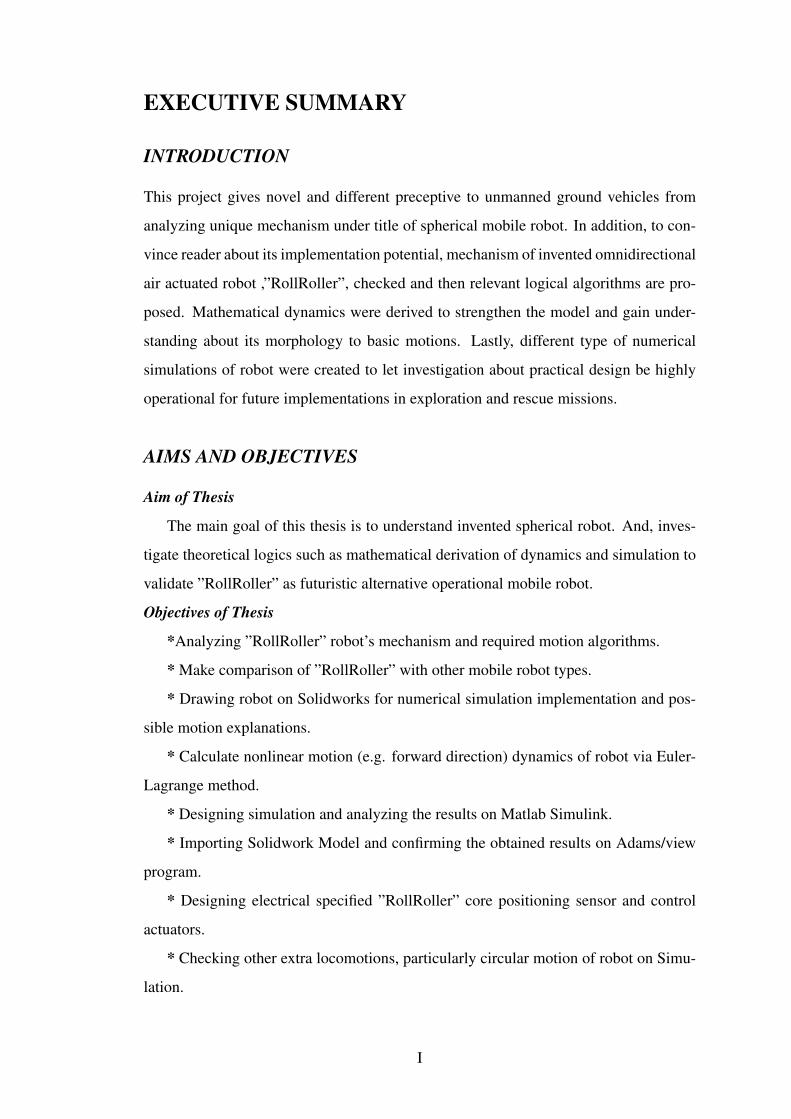
EXECUTIVE SUMMARY
INTRODUCTION
This project gives novel and different preceptive to unmanned ground vehicles from
analyzing unique mechanism under title of spherical mobile robot. In addition, to con-
vince reader about its implementation potential, mechanism of invented omnidirectional
air actuated robot ,”RollRoller”, checked and then relevant logical algorithms are pro-
posed. Mathematical dynamics were derived to strengthen the model and gain under-
standing about its morphology to basic motions. Lastly, different type of numerical
simulations of robot were created to let investigation about practical design be highly
operational for future implementations in exploration and rescue missions.
AIMS AND OBJECTIVES
Aim of Thesis
The main goal of this thesis is to understand invented spherical robot. And, inves-
tigate theoretical logics such as mathematical derivation of dynamics and simulation to
validate ”RollRoller” as futuristic alternative operational mobile robot.
Objectives of Thesis
*Analyzing ”RollRoller” robot’s mechanism and required motion algorithms.
* Make comparison of ”RollRoller” with other mobile robot types.
* Drawing robot on Solidworks for numerical simulation implementation and pos-
sible motion explanations.
* Calculate nonlinear motion (e.g. forward direction) dynamics of robot via Euler-
Lagrange method.
* Designing simulation and analyzing the results on Matlab Simulink.
* Importing Solidwork Model and confirming the obtained results on Adams/view
program.
* Designing electrical specified ”RollRoller” core positioning sensor and control
actuators.
* Checking other extra locomotions, particularly circular motion of robot on Simu-
lation.
I
ACHIEVEMENTS
I) RollRoller’s manners and structure were studied and its algorithms were developed.
II) Nonlinear dynamics and state-space model for ”RollRoller” basic motion with
either friction or without were calculated.
III) Matlab Simulation model designed and results were verified.
IV) ”RollRoller” Solidworks model created and imported to Adams/view Numeri-
cal Simulation.
V) Adams/view model visualized and results were inspected.
VI) Turning motion were designed on Adams/view simulation and results plotted.
CONCLUSIONS
The proposed novel robot, ”RollRoller”, performs successfully as expected in all the
stages of simulations ( i.e. Matlab Simulink and Adams/view simulation). And obtained
results are validating that this spherical mobile robot can be very promising alternative
for current unmanned ground vehicles (e.g. Legged, Wheeled and Snake ) in practice.
Space investigations, rescue missions and other civilian activities are the possible tasks
that RollRoller is able to enroll in near future applications.
II

ABSTRACT
This paper introduces novel air actuated spherical robot called ”RollRoller”. The Roll-
Roller robot consists of two essential parts: tubes covered with a shell as a frame and
mechanical controlling parts to correspond movements. The RollRoller is proposed to
be high potential alternative for exploration and rescue missions robots because robot
utlizing its locomotion via all possible deriving methods (gravity, torque and angular
momentum forces). In beginning , characteristic and role of each of component and
features were explained. Next, to determine the uniqueness of this robot the known and
other extra possible motions are shown by proposing their own algorithmic movements.
To illustrate main motion of this robot was inherent to mathematical models, the for-
ward direction dynamical behavior on flat surface was derived. Additionally, Matlab
Simulink was used to plot the results to validate the behavior for both fractional and
non-fractional terrains. Lastly, after desgining the model of robot in Solidworks Pro-
gram, Adams/View visualization software ( the robot simulated form ) was utilized to
proof the Matlab Simulink results and to show the more detailed and complete form of
locomotion including the forward direction and circular locomotion in proposed robot.
III
ACKNOWLEDGEMENTS
Initially, i would like to express my sincere gratitude to my project supervisor Prof.Sandor
M. Veres about his priceless support in developing my invention as research thesis. His
noteworthy advises and given opportunities, helped me to analyze this robot more in
advance and also it has given a chance to implement in practice in near future.
In addition, i would like to extend my special appreciation to my B.Sc. supervisor
Dr. Larissa Khodadadi, her unforgettable life long guide boosted me in developing
my project. And also, her inspiring impact during my B.Sc. studies is main reason in
my enhanced creativity and problem solving perspective. Also, Special thanks to all
academic members and stuff in University of Sheffield that were helping me during this
project. Particularly my M.Sc. Personal Tutor Dr.Jun Liu for his vise advices to let me
see the problems more clear.
I dedicate this thesis to my beloved parent and friends specially Ataback Maleki and
Pedram Purali, who have stand beside me during all hardships and always motivated me.
Their continues support have helped me mature into person i am today.
IV
Contents
1 Introduction 1
1.1 Background and Motivation of Mobile Robots . . . . . . . . . . . . . . 2
1.1.1 Wheeled Robots . . . . . . . . . . . . . . . . . . . . . . . . . 2
1.1.2 Legged Robots . . . . . . . . . . . . . . . . . . . . . . . . . . 2
1.1.3 Snake Robots . . . . . . . . . . . . . . . . . . . . . . . . . . . 4
1.2 Spherical Robots History And Characteristic . . . . . . . . . . . . . . . 5
1.2.1 Torque Driven . . . . . . . . . . . . . . . . . . . . . . . . . . 5
1.2.2 Gravity Driven . . . . . . . . . . . . . . . . . . . . . . . . . . 7
1.2.3 Angular Momentum Driven . . . . . . . . . . . . . . . . . . . 8
1.2.4 Other Types of Spherical Robots . . . . . . . . . . . . . . . . . 9
1.3 Motivation of RollRoller Invention . . . . . . . . . . . . . . . . . . . . 10
1.4 Application Opportunities and Potentials . . . . . . . . . . . . . . . . . 12
1.4.1 Rescue . . . . . . . . . . . . . . . . . . . . . . . . . . . . . . 12
1.4.2 Exploration . . . . . . . . . . . . . . . . . . . . . . . . . . . . 13
1.4.3 Industrial . . . . . . . . . . . . . . . . . . . . . . . . . . . . . 14
1.4.4 Social Involvement . . . . . . . . . . . . . . . . . . . . . . . . 14
1.5 Aims and Objectives . . . . . . . . . . . . . . . . . . . . . . . . . . . 15
1.5.1 Aims . . . . . . . . . . . . . . . . . . . . . . . . . . . . . . . 15
1.5.2 Objectives . . . . . . . . . . . . . . . . . . . . . . . . . . . . . 15
1.5.3 Project Management . . . . . . . . . . . . . . . . . . . . . . . 16
2 RollRoller Features and Motion Analysis 17
2.1 Physical Features . . . . . . . . . . . . . . . . . . . . . . . . . . . . . 18
2.1.1 Frame of Robot . . . . . . . . . . . . . . . . . . . . . . . . . . 18
2.1.2 Mechanical Instruments . . . . . . . . . . . . . . . . . . . . . 20
V
2.2 Movements Algorithm . . . . . . . . . . . . . . . . . . . . . . . . . . 20
2.2.1 Forward Locomotion . . . . . . . . . . . . . . . . . . . . . . . 20
2.2.2 Circular Turning . . . . . . . . . . . . . . . . . . . . . . . . . 22
2.2.3 Angular Locomotion . . . . . . . . . . . . . . . . . . . . . . . 23
2.2.4 Slide Locomotion . . . . . . . . . . . . . . . . . . . . . . . . . 24
2.2.5 Jump Locomotion . . . . . . . . . . . . . . . . . . . . . . . . 25
2.3 Electrical Sensors Overview . . . . . . . . . . . . . . . . . . . . . . . 26
3 Mathematical Analysis 28
3.1 Basic Motion Dynamics Calculations . . . . . . . . . . . . . . . . . . 28
3.2 Fractional Motion Dynamics . . . . . . . . . . . . . . . . . . . . . . . 34
4 Visualization Results And Simulink 36
4.1 Matlab Simulink . . . . . . . . . . . . . . . . . . . . . . . . . . . . . 36
4.1.1 Basic Motion simulation . . . . . . . . . . . . . . . . . . . . . 36
4.1.2 Simulation of Motion with Fraction . . . . . . . . . . . . . . . 41
4.2 Adams/View Numerical Simulation . . . . . . . . . . . . . . . . . . . 43
4.2.1 Direct Generic Motion . . . . . . . . . . . . . . . . . . . . . . 43
4.2.2 Algorithmic Forward Direction Motion . . . . . . . . . . . . . 48
4.2.3 Turning Motion . . . . . . . . . . . . . . . . . . . . . . . . . . 53
5 Conclusion 56
6 Future Work 57
REFERENCES 58
A The Matlab Code 64
B Parts Relation In Adams/View Simulation 65
VI
List of Figures
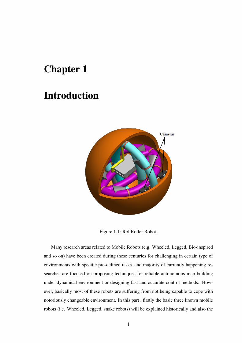
1.1 RollRoller Robot. . . . . . . . . . . . . . . . . . . . . . . . . . . . . . 1
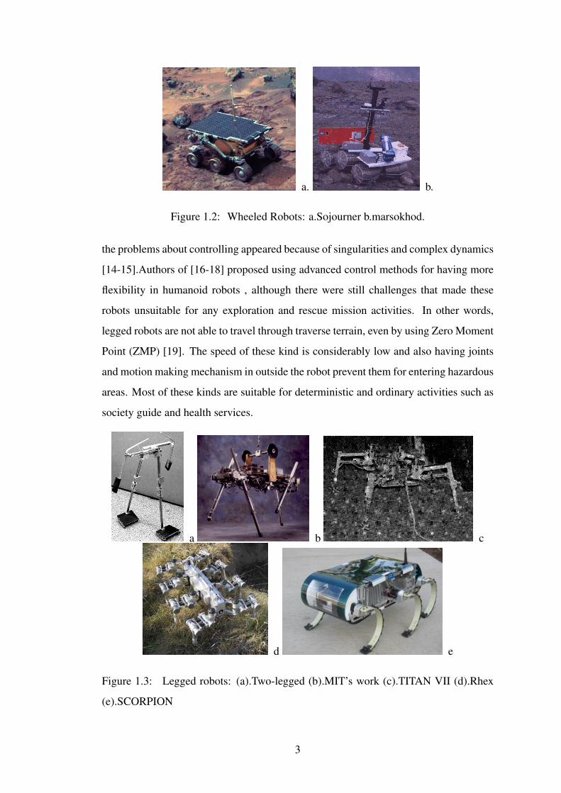
1.2 Wheeled Robots: a.Sojourner b.marsokhod. . . . . . . . . . . . . . . . 3
1.3 Legged robots: (a).Two-legged (b).MIT’s work (c).TITAN VII (d).Rhex
(e).SCORPION . . . . . . . . . . . . . . . . . . . . . . . . . . . . . . 3
1.4 Snake robots: (a).Hirose’s robot,(b).ACM-R3 ,(c).Perambulator-II . . . 5
1.5 Past proposed spherical robots. . . . . . . . . . . . . . . . . . . . . . . 6
1.6 Unique form of torque driven method. . . . . . . . . . . . . . . . . . . 7
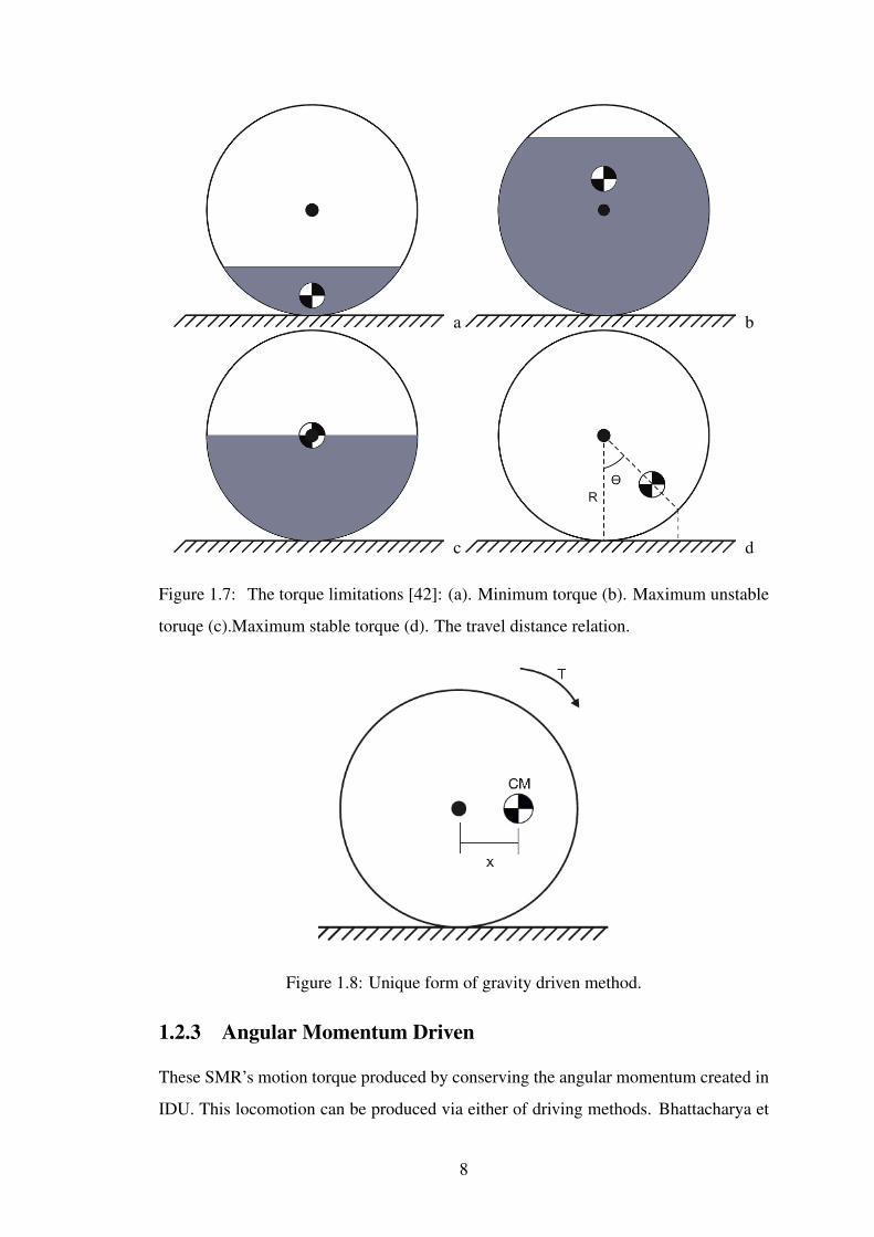
1.7 The torque limitations [42]: (a). Minimum torque (b). Maximum un-
stable toruqe (c).Maximum stable torque (d). The travel distance relation. 8
1.8 Unique form of gravity driven method. . . . . . . . . . . . . . . . . . . 8
1.9 The deformobale robot’s ramp climb and jump [44]. . . . . . . . . . . . 10
1.10 The Hybrid SMR [45]. . . . . . . . . . . . . . . . . . . . . . . . . . . 10
1.11 Electroactive Elastomeric Deformable Rover [46]. . . . . . . . . . . . . 11
1.12 The Gantt Chart . . . . . . . . . . . . . . . . . . . . . . . . . . . . . . 16
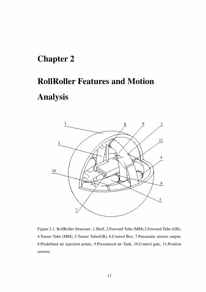
2.1 RollRoller Structure: 1.Shell, 2.Forward Tube (MM),3.Forward Tube
(GB), 4.Turner Tube (MM), 5.Turner Tube(GB), 6.Control Box, 7.Pneu-
matic motors output, 8.Predefined air injection points, 9.Pressurized air
Tank, 10.Control gate, 11.Position sensors. . . . . . . . . . . . . . . . 17
2.2 (a’). Specified parts: a. Spherical Shell, b. Forwarder tube, c. Turner
tube. d. Copper core. (b’).Mechanical equipments: M1. Control Gate,
M2. Input hole for pressurized air, M3. Motor Box, M4.Output of
pressurized air. (c’). Flattened control gate. . . . . . . . . . . . . . . . 19
2.3 Rolling motion model along O-y. . . . . . . . . . . . . . . . . . . . . . 21
2.4 The division of tube. . . . . . . . . . . . . . . . . . . . . . . . . . . . 21
2.5 Cycle of circular locomotion. . . . . . . . . . . . . . . . . . . . . . . . 23
VII

2.6 Required gestures for angular motion. . . . . . . . . . . . . . . . . . . 23
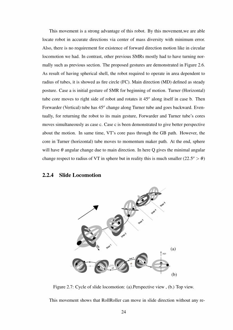
2.7 Cycle of slide locomotion: (a).Perspective view , (b.) Top view. . . . . . 24
2.8 Cycle of Angular motion (a).Initial formation. (b) Jumping Operation. . 25
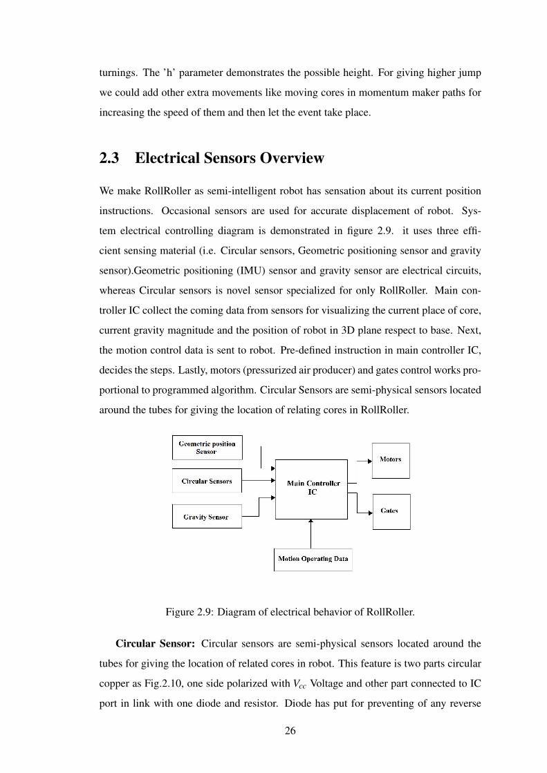
2.9 Diagram of electrical behavior of RollRoller. . . . . . . . . . . . . . . 26
2.10 Circular sensor. . . . . . . . . . . . . . . . . . . . . . . . . . . . . . . 27
3.1 Rolling motion geometric model along O-y. . . . . . . . . . . . . . . . 29
3.2 The unit vectors, angular and linear velocities. . . . . . . . . . . . . . . 30
4.1 The inner block diagram of x2 and x3 state-equations. . . . . . . . . . . 37
4.2 Block diagram of function E. . . . . . . . . . . . . . . . . . . . . . . . 38
4.3 Generic block diagram of state-space model. . . . . . . . . . . . . . . . 38
4.4 (a). Displacement of core and sphere (b). Velocity for both core and
sphere. . . . . . . . . . . . . . . . . . . . . . . . . . . . . . . . . . . . 39
4.5 Pulse input to system (τ). . . . . . . . . . . . . . . . . . . . . . . . . . 39
4.6 (a). Velocity response of sphere and core states with double pulse input
to system (2τ) (b). Velocity response of sphere and core states with
higher pulse input to system (6τ) . . . . . . . . . . . . . . . . . . . . . 40
4.7 The inner updated block diagram of x2 and x4 state-space models. . . . 41
4.8 (a). Displacement of core and sphere with friction (b). Velocity for both
core and sphere with friction. . . . . . . . . . . . . . . . . . . . . . . . 42
4.9 Solidworks Design (Inches Unit). . . . . . . . . . . . . . . . . . . . . . 44
4.10 (a). Fixed Joint between GB and VT (b). Revolute joint between Con-
trol gate and joint (c). Body properties of VT (d).Input torque to pen-
dulum. . . . . . . . . . . . . . . . . . . . . . . . . . . . . . . . . . . 45
4.11 RollRoller’s Adams/view simulation design. . . . . . . . . . . . . . . . 46
4.12 (a). Displacement of core and sphere result on Adams/PostProcessor
(b). Velocity for both core and sphere result on Adams/PostProcessor. . 46
4.13 The translational momentum and displacement in Y axis. . . . . . . . . 47
4.14 The angular acceleration of total magnitude and Z axis. . . . . . . . . . 48
4.15 (a) The special Controller gate for Adam’s simulation (b).Modified sim-
ulation model. . . . . . . . . . . . . . . . . . . . . . . . . . . . . . . . 49
4.16 (a). Control Gate 1 reference input (b). Control Gate 2 reference input. . 49
VIII
4.17 Sequences of numerical Adams/view simulation with following algo-
rithm motion. . . . . . . . . . . . . . . . . . . . . . . . . . . . . . . . 50
4.18 (a). Locomotion of ”RollRoller” with algorithm (b).Speed of ”Roll-
Roller” with algorithm. . . . . . . . . . . . . . . . . . . . . . . . . . . 51
4.19 (a). Core locomotion comparison (b). Sphere displacement comparison. 52
4.20 (a). Y axis displacement (b). Translational momentum along Y axis. . . 54
4.21 (a).The circular locomotion added parts (b). Circular locomotion coor-
dinates. . . . . . . . . . . . . . . . . . . . . . . . . . . . . . . . . . . 55
4.22 3D movement. . . . . . . . . . . . . . . . . . . . . . . . . . . . . . . . 55
B.1 (a).Bodies (b).Connectors (c).Forces . . . . . . . . . . . . . . . . . . . 65
B.2 Normal Locomotion Definition: (a).Bodies (b).Connectors (c).Forces
part 1 (d). Forces part 2 . . . . . . . . . . . . . . . . . . . . . . . . . . 66
B.3 The relativities of parts in Adams/view simulation for normal locomotion 67
B.4 Circular Motion Definition: (a).Bodies (b).Connectors (c).Forces part 1
(d). Forces part 2 . . . . . . . . . . . . . . . . . . . . . . . . . . . . . 68
B.5 The relativities of parts in Adams/view simulation for circular locomotion 69
IX

List of Tables
2.1 CHARACTERISTIC OF CONSIDERED NYLON 12 MATERIAL. . . 18
2.2 FUNCTIONS OF FORWARD MOVEMENT . . . . . . . . . . . . . . 22
3.1 NOMENCLATURE OF DYNAMIC ANALYSIS . . . . . . . . . . . . 29
4.1 VISUALIZATION SETUP OF ”RollRoller”. . . . . . . . . . . . . . . 36
List of Abbreviation
3D Three Dimensional
CH4 Methane
CM Center of Mass
CO2 Carbon Dioxide
DOF Degree Of Freedom
FC Fire Circle
FT Forwarder Tube
GB Gravity Breaker
GPS Global Positioning System
HT Horizontal Tube
IC Integrated Circuit
IDU Internal Driving Unit
IMU Inertia Measurement Unit
MD Main Direction
MM Momentum Maker
NASA National Aeronautics and Space Administration
PD Penetration Depth
SMR Spherical Mobile Robot
TT Turner Tube
UGV Unmanned Ground Vehicle
VT Vertical Tube
ZMP Zero Moment Point
XI
Chapter 1
Introduction
Figure 1.1: RollRoller Robot.
Many research areas related to Mobile Robots (e.g. Wheeled, Legged, Bio-inspired
and so on) have been created during these centuries for challenging in certain type of
environments with specific pre-defined tasks ,and majority of currently happening re-
searches are focused on proposing techniques for reliable autonomous map building
under dynamical environment or designing fast and accurate control methods. How-
ever, basically most of these robots are suffering from not being capable to cope with
notoriously changeable environment. In this part , firstly the basic three known mobile
robots (i.e. Wheeled, Legged, snake robots) will be explained historically and also the
1

pros and cons of each type will be pointed out with noteworthy comparison. Secondly,
the main focus will be on spherical robots types and historical background. And in next
section, ”RollRoller”’s motivation, advantages and disadvantages and also potentiality
in near future practical implementation will be explained. Lastly, the achieved aims and
objectives with timetable deeds have been written.
1.1 Background and Motivation of Mobile Robots
1.1.1 Wheeled Robots
The Wheeled Mobile Robot was started to be under the scope seriously by end of 19th
[1] in which possible wheeled structures proposed and dynamically derived to under-
stand mobility. Next, The Sojourner Rover [2] was landed on Mars by using successful
wheeled mechanism, figure 1.2 a shows this robot on mission. Other related studies
were taken place during those years [3-5]. However, having fixed mechanism stopped
them toward entering to uneven surface and unpredictable environments. The Mar-
sokhod [3] was able only to over come certain roughness proportional to wheel size
(figure 1.2 b). Furthermore, likelihood about appearing unknown environment condi-
tion was so high such as sand storm, toxic rains and so on so the robots was not able
to performance acceptably. Hybtor [6], Spacecat [7] and nanorovers [8-10] were other
types with complex control methods that were proposed in which the previous prob-
lems were still existed hence they were suitable for places that the specifications and
area were deterministic. eventually, latest designed flexible rovers [11-12] still were not
suitable to enter places with stochastic atmosphere because the fundamental designs are
still untouched and also actuators and motion making wheels were in contact with out-
side. These were main reasons that prevent this type to enroll in rescue mission and
even more the period of involvement of pure wheeled robot in exploration missions in
outer surface has got no attraction in these years research ares.
1.1.2 Legged Robots
Passive Two-Legged robot’s dynamics analyzed firstly in 1990 [13] by McGeer. During
early 20th human-like legged robots with active joints were designed (figure 1.3 a) but
2
a. b.
Figure 1.2: Wheeled Robots: a.Sojourner b.marsokhod.
the problems about controlling appeared because of singularities and complex dynamics
[14-15].Authors of [16-18] proposed using advanced control methods for having more
flexibility in humanoid robots , although there were still challenges that made these
robots unsuitable for any exploration and rescue mission activities. In other words,
legged robots are not able to travel through traverse terrain, even by using Zero Moment
Point (ZMP) [19]. The speed of these kind is considerably low and also having joints
and motion making mechanism in outside the robot prevent them for entering hazardous
areas. Most of these kinds are suitable for deterministic and ordinary activities such as
society guide and health services.
a b c
d e
Figure 1.3: Legged robots: (a).Two-legged (b).MIT’s work (c).TITAN VII (d).Rhex
(e).SCORPION
3

On the other hand, MacGee as pioneer at multi-legged robots, formulated them
mathematically [20].Simultaneously the scholars at MIT started working these type be-
cause of their extra Degree of freedom (DOF)[21] which results a practical develop-
ments such as figure 1.3 b. Multi-legged robots were more stable and tolerant toward
hilly surfaces by comparison with two-legged robots but logically more joints led more
complex dynamics and sophisticated manners of robot. As consequence , they were
requiring advance control methods with high speed calculation time which still is under
development within these years. TITAN VII [22] and Rhex [23] figure(1.3 c-d) also
were other developed multi-legged robots with their own benefits as alternative actu-
ation mechanisms for this kind. There were stability test on SCORPION ( 8 legged
mobile robot) when it loses its two legs [24] but still it was lack of practice for real
world. As a result, Legged Robots are commonly known for their extra DOF but by
getting involve in generic places, their legs may stock or controllers may face ambiguity
or serious errors toward unpredicted changes. However, combination of this kind with
wheeled structure is newly used as convenient practical deeds, as an example NASA’s
”Curiosity” robot sent to mars for doing geological sampling.
1.1.3 Snake Robots
Biologically inspired snake robots studied and designed in 1993 by Hirose (figure 1.4
a) [25]. Although, he formulated the ground friction, temperature and snake shape in
his dynamics, the robot was able to do only lateral undulation. Furthermore, having
complex dynamics and environmentally dependent characteristics made these type less
attractive, as a result it found more practical in activities like pipeline inspections [26].
Till now different snake robots such as ACM-R3 [27], Perambulator-II [28] and other
models [29-30] have been theoretically evaluated and developed. Nevertheless , they
were not operational for any serious activities since they were responding slow and
sensitive to outside world. Scholars in [31] designed snake robot for rescue mission but
research was on theoretical base. Overall, although snake robots have joints outside,
there is way to cover it up. But again not having enough space for extra instruments,
not having jumping capability and high likelihood of stocking/locking under crashed
buildings stops them from being superior choice. Because of that this type is still under
development from mechanical and controller design aspects.
4

a b c
Figure 1.4: Snake robots: (a).Hirose’s robot,(b).ACM-R3 ,(c).Perambulator-II
1.2 Spherical Robots History And Characteristic
Spherical Robots are revolutionary mobile robots because of their symmetrical surface
by comparison with other types. In this type all required locomotion motions and other
instruments are just wrapped inside spherical shell. Spherical Mobile Robots (SMRs)
can move in all directions, swing , spin proportionally or individually and even can jump
in all kind of unknown terrains ( all proposed mechanism types are shown in figure 1.5).
As result, SMRs are being considered to enroll in serious and hazardous operations
such as rescue or exploration missions . Not only this kind is able to show phenomenal
potential in serious tasks but also can have active role in industrial and social services.
On the other hand, sophistication of actuation mechanism in SMR’s and limitation of
activities that are simple in rest of mobile robots particularly in practical areas led this
model to not to be as attractive as them. About driving mechanism spherical mobile
robots can be divided into three categories as general: Torque , Gravity and Angular
Momentum Driven.
1.2.1 Torque Driven
In Torque Driven method , sphere gets its motivation force by using motors reaction
force directly connected to spherical shell inner surface. This concept firstly was im-
plemented and analyzed about mono-directional dynamics by Halme et al in 1996 as
figure 1.5 [32].
The figure 1.6.a shows the sphere with centralized mass which can be considered as
general definition, and also the spherical shell mass by comparison of total robot mass
is neglected. Figure 1.6.b can be showed as unique form of this kind. The center of
mass in this method shifted with d distance from sphere center and outer shell is con-
5

Figure 1.5: Past proposed spherical robots.
nected to this CM.In other words, it can be imagined as pendulum driven mechanism.
By giving angular change via ”u” torque in counter-clockwise direction, connected cen-
tralized mass object moves. Then, the robot gains opposed torque from it so makes total
sphere to displace along terrain. This motion maximum speed can be estimated when
the pendulum moves the CM to around the horizontal line region. Figure 1.7 illustrates
the power of sphere motion respect to CM. And, Distance from ground is defining the
smallest angular change with relativity to speed hence as much as the center of mass
moves beneath the center and reaches to ground, although utilizing the accurate motions
become possible, sphere is not capable of having high torque reaction during locomo-
tion. The same manner happens when the center of mass pass and goes upper than
sphere’s center, this may achieve the highest possible torque but if it is using pendu-
lum driving mechanism for instance, system will be unstable. As result, maximum safe
torque is achievable with only locating at center as figure 1.7 c, however due to relative
connection between center of sphere, beam and mass it is not practically achievable.
The approximated travel distance with its relation to sphere radiance and angle
change (θ ) derived from geometric characteristic (figure 1.7 c).
d(rad) =2πR360
θ (1.1)
Kinetic relativity due to angular change in pendulum shows that as distance from verti-
cal line’s CM increases , the travel raises proportional to velocity.
Single wheel structure was other used mechanism in which had only one degree of
freedom (DOF) and internal driving unit was unstable toward overcoming serious up-
hill or ramp.Bacchi et al introduced wheeled car placed in sphere changing the center of
mass by displacing of the car [33]. Although ”SPHERICLE” had simple IDU structure,
it was occupying the whole sphere and also were unstable for sudden uneven terrains.
6

a b
Figure 1.6: Unique form of torque driven method.
Then, a pendulum driven toy ball proposed and analyzed from physiological and safety
aspects [34] (no physical stability in motor high speed of motors). RoBall [35] and
Volvolt [36] as latest models of torque driven IDU were still not able to have perfect
omni-directional movement (i.e. errors in circular and slide motions).
1.2.2 Gravity Driven
In the Gravity Driven IDU, position of robot changes with respect to center of mass
displacement(figure 1.8). However, there is no hard relation with outer shell in this
motion typology. The gravitational acceleration takes place by moving center of mass
with x distance inside sphere to equalize the center of mass. Mukherejee et al developed
”Spherobot” as pioneer in this field in 1999, moving masses on four spokes connected
from center of sphere to surface of shell as mechanism [37], to generate required mo-
tion. Javadi did further analysis on this concept about dynamic and trajectory planning
[38-39]. Nevertheless, Gravity driven IDU alone were suffering from lack of continues
acceleration and high velocities and they weren’t able to climb ramps or rough terrains
as well. In contrast with torque driven this locomotion can have more accurate and slow
motions along the path.
7
a b
c d
Figure 1.7: The torque limitations [42]: (a). Minimum torque (b). Maximum unstable
toruqe (c).Maximum stable torque (d). The travel distance relation.
Figure 1.8: Unique form of gravity driven method.
1.2.3 Angular Momentum Driven
These SMR’s motion torque produced by conserving the angular momentum created in
IDU. This locomotion can be produced via either of driving methods. Bhattacharya et
8

al proposed two perpendicular motors inside sphere in 2000 [40]. Motors with creating
individual or co-operative momentum generate total movement for spherical robot but
having complex motion mechanics and dependency on rotor’s speed decrease robot’s
efficiency. In 2009, scholars developed control method for angular momentum force
by using the pendulum structure with detached relation of spherical shell [41]. Also,
The result was controlled rotation with angular momentum of IDU. However, generally
this type of driving mechanism is not suitable to be main stream for robot’s motion
and it may find more practical usage in outer space or places that gravity and frictional
reaction-torque are not efficient anymore. Having considerably small magnitude of dis-
placement force , high sensitivity of disturbance and noise makes them weak alternative
from other driving IDUs. From then on, many researches have been taken place to com-
bine angular momentum with other methods. For example, Schroll designed and built
”Gyrosphere robot” that was able to use gravitational and angular momentum forces to
have different motions in 2008 [42]. Another combination of direct driving ( Torque
Reaction) and angular momentum force was developed by Jia et al in 2009 [43]. These
latest SMRs’ control methods and ability to behave perfectly in interchangeable envi-
ronment were considerably low yet again. Even more, they mostly were lack of jumping
capability and enough space to other required instruments.
1.2.4 Other Types of Spherical Robots
In 2005 a deformable SMR was studied by Sugiyama to pass crawl rough terrains and
jump as figure 1.9 [44]. The deformable SMR consisted of eight wire connected to
elastic surface in which changing length of each of these wires reform the SMR. De-
spite these capabilities, the robot was extremely sensitive to be unstable due to complex
mechanism. Consequently, robot still is under development for practical utilizations.
Phipps et al. [45] designed rolling disk-like biped hybrid robot in 2008 which was
able to walk, climb and roll as figure 1.10. Efficiency of rolling in robot was validated
as highest one from walking but the dynamical motion and control methods didn’t de-
signed yet in which it may contain more complexity by comparison with fixed SMRs.
scientists have been working on a new deformable spherical rover actuating with heat
input to sphere surface(figure 1.11) [46]. However; Electroactive Elastomeric Actuators
make system unsuitable in today tasks because this phenomenon requiring extra heat-
9
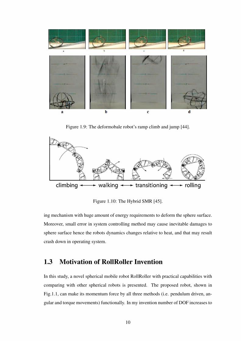
Figure 1.9: The deformobale robot’s ramp climb and jump [44].
Figure 1.10: The Hybrid SMR [45].
ing mechanism with huge amount of energy requirements to deform the sphere surface.
Moreover, small error in system controlling method may cause inevitable damages to
sphere surface hence the robots dynamics changes relative to heat, and that may result
crash down in operating system.
1.3 Motivation of RollRoller Invention
In this study, a novel spherical mobile robot RollRoller with practical capabilities with
comparing with other spherical robots is presented. The proposed robot, shown in
Fig.1.1, can make its momentum force by all three methods (i.e. pendulum driven, an-
gular and torque movements) functionally. In my invention number of DOF increases to
10
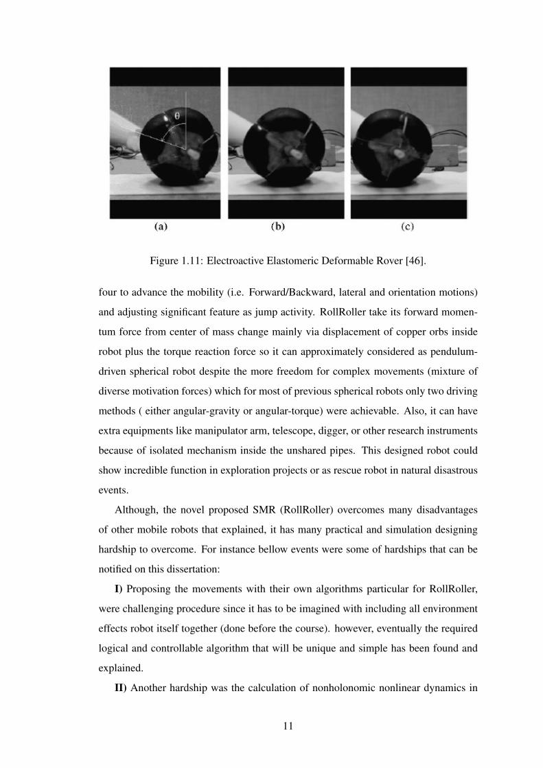
Figure 1.11: Electroactive Elastomeric Deformable Rover [46].
four to advance the mobility (i.e. Forward/Backward, lateral and orientation motions)
and adjusting significant feature as jump activity. RollRoller take its forward momen-
tum force from center of mass change mainly via displacement of copper orbs inside
robot plus the torque reaction force so it can approximately considered as pendulum-
driven spherical robot despite the more freedom for complex movements (mixture of
diverse motivation forces) which for most of previous spherical robots only two driving
methods ( either angular-gravity or angular-torque) were achievable. Also, it can have
extra equipments like manipulator arm, telescope, digger, or other research instruments
because of isolated mechanism inside the unshared pipes. This designed robot could
show incredible function in exploration projects or as rescue robot in natural disastrous
events.
Although, the novel proposed SMR (RollRoller) overcomes many disadvantages
of other mobile robots that explained, it has many practical and simulation designing
hardship to overcome. For instance bellow events were some of hardships that can be
notified on this dissertation:
I) Proposing the movements with their own algorithms particular for RollRoller,
were challenging procedure since it has to be imagined with including all environment
effects robot itself together (done before the course). however, eventually the required
logical and controllable algorithm that will be unique and simple has been found and
explained.
II) Another hardship was the calculation of nonholonomic nonlinear dynamics in
11

spherical robot in which after studying many papers and doing analysis, most con-
venient and useful novel dynamics derived for RollRoller IDU mechanism that let us
estimate the linearized form for designing required controller in future researches. Ad-
ditionally, more general form generated with adding frictional effects to robot.
III) Designing tubes’ and cores’ size, mass and materials type were another serious
challenge since one of most essential decisive point was its characteristics making robot
logical and possible to be implemented. Hence, first the importance of each parameters
defined and then designed relative to priority. For instance, changing the size of robot
doesn’t have direct relation with IDU mechanis. Nevertheless, at end all the input data’s
and physical definitions made to be practically applicable in this dissertation.
IV)Lastly, air input force that makes the corresponded core to move, was problem-
atic to design. Particularly, during the designing the numerical simulation Adams/view
due to complexity of nonlinear air dynamics it was estimated and designed with solid
object (pendulum pusher) instead. However, this phenomenon didn’t have any negative
contribution on changing the expected results.
This paper is represented in three main sections. Section 2 involves physical feature
of RollRoller. The following subsections are frame of robot, explanation of mechanical
instruments, Movement algorithms and explaining electrical sensors. Derived Forward
direction dynamics with and without friction are demonstrated in Section 3. Section
4 is written about different simulation methods(Matlab Simulink and Adams/view nu-
merical simulation).
1.4 Application Opportunities and Potentials
1.4.1 Rescue
1.Fire Rescue Robot: ”RollRoller” robot with a covered fire redundant alloy around
the spherical shell can involve in rescue missions as fire extinguisher since it has got
considerable space inside itself that let robot to have other instruments without interac-
tion with SMR’s main mechanism. Furthermore , this type is more flexible, accurate
and faster than human being fire fighter. For example, it can enter to burning crashed
building , analyze surrounding by sensors , find the victims , check the area temperature
, find all the possible safe paths with low CO2 and CH4 level , reach place without af-
12

fection from fire temperature , use fire extinguisher nozzle to clear path and let victims
leave building successfully or send signal to human fire fighters to take the situation un-
der control. Additional way is passive enrollment as assistant rescue robot to help fire
fighters in caring heavy and sensitive materials in their coverage. Having fast response
to prevent any damage to fire fighter or victim is another way to be utilized it as active
assistant rescue robot.
2.Nuclear or Hazardous Area Inspector: First and foremost, safety of pipelines
and tanks in sensitive plants such as nuclear plant is crucial. The Fukushima nuclear ac-
cident in Japan showed the importance of this phenomenon in which wrong display on
air articulator pipes made the Fukushima district inhabitable. As a solution, RollRoller
can inspect leakage or damage of pipelines and tanks. In next stage, By advancing
the robot to reparteeing items , simultaneous sense and act may be implemented to
repair. Also, the same as Fire rescue activity this robot can work actively as rescue
mobile robot. Proposed SMR is stronger than other type of mobile robots (e.g. Legged,
Wheeled and snake) since initially all the actuation and mechanical features are warped
in sphere. Secondly, SMRs are more environment friendly because of their symmetric
shape.
1.4.2 Exploration
1.Autonomous Ground Space Exploration Vehicle: Space mobile robots are de-
signed for planetary exploration and collecting sample during space mission. ”Roll-
Roller” is revolutionary type for this task since past robots (e.g. Mars Rover, Curiosity)
were only used in known and deterministic environment but ”RollRoller” doesn’t re-
quire satellites observation about weather, doesn’t need 24 hours live observation to re-
spond any unknown event by operators, doesn’t required to have very complex control
agents or huge structure to prevent it from collapsing.As a result , with medium scale
and low budget sending an mobile robot explorer to any planet wont be impossible any-
more.Lastly, first polar explorer spherical robot ”tumbleweed rover” was proposed by
NASA [47] which shows it’s potential for future investigations.
2. Space Repairer: Because ”RollRoller” can make Angular momentum force,
Torque reaction force and combination of those, it will be practical for outer space
13
activities without gravity. Consequently, non-gravitational places like space stations
or satellites will be able to use this type to repair their facilities without sending an
astronaut directly.
3. Mobile Sailing Robot: Due to spherical shell formation, vehicle is able to move
in both ground and water. However, robot has to have extra equipments to have appli-
cable motion in water.
1.4.3 Industrial
1.Pipelines Inspector Robot: Gas and water pipelines are spread around cities. De-
tecting the problematic pipes is important challenge to cut extra costs from changing
wrong pipe. By including the ”RollRoller” in this inspection activities through pipes,
robot can detect problematic part easily.
2.Dam Inspector: Other similar usage as pipelines, is dam observation and main-
tenance. Dam’s control gates and power generators are those parts that not only is not
reachable easily by human being but also requires serious inspections about prevent-
ing possible crash down in electrical generation process.Generally this robot can enter
not human friendly places then inspect , analyze , understand problem, send requiring
information to operators and lastly do maintenance on broken or problematic part.
3.Agriculture: In agriculture sector identifying bugs, spraying, removing waste
plants are time consuming jobs. Special designed ”RollRoller” for farming industry
moving through farms , spraying required places to prevent bugs or using specific in-
strument to take out the waste plants. As consequence, this phenomenon will increase
quality of farming products and at same time will raise the income for farmers.
4.Building’s Painter Robot: if a paint caring spherical layer placed on robot be-
cause of jumping and other coordinative movements on robot, it can perfectly jump and
use wall reflected action. This process can be continued and it will paint whole room.
1.4.4 Social Involvement
1. Social Guide: Assisting people in social places is another noteworthy task. For
instance , in restaurant assisting costumers to their places , taking orders and giving
payment bills, will be suitable for deeds with less time-consumption and better service
14

quality in tasks instead of human waiters hence considerably it will increase the income
of business owners and ease the employees’ and costumers’ job. Furthermore,in con-
trast with other robots if any unknown object suddenly take the robot out of its task
trajectory , without taking any harm to its IDU ,”RollRoller” can return without any
sophisticated feedback control algorithms in which it required mostly for joined robots.
2. Children Toy: ”RollRoller” doesn’t contain any harmful instruments outside
the shell. And also this robot via camera, Inertia Measurement Unit (IMU) and Global
Positioning System(GPS) , parents easily will be able to track their children and check
them in anytime. Moreover, with using defensive algorithms it will able to protect chil-
dren from strangers.
1.5 Aims and Objectives
1.5.1 Aims
The project aims to analyze novel spherical mobile robot (RollRoller) in which will
have futuristic usage in both academic and industrial areas. The proposed robot will be
able to overcome many problems by comparison with its own kind and also is a superior
alternative for other Unmanned ground Vehicle types (e.g. Humanoid, wheeled and bio-
inspired robot). In this project the robot’s derived dynamics are going to be analyzed to
validate motion mechanisms and gain understanding of complex behaviors. In the last
phase of project suitable actuators and sensors will be designed for RollRoller.
1.5.2 Objectives
1. Developing novel RollRoller robots Mechanism.
2. Compare previous proposed robots.
3. Drawing robot on Solidworks for numerical simulation implementation and possible
motion explanations.
4. Calculate motion (e.g. forward direction) dynamics of robot.
5. Simulate and analyze the results on Matlab Simulink.
6. Validate the results by designing the robot on Adams/view.
15

7. Design actuator and sensors if the logical and acceptable results are obtained.
8. Analyze other extra locomotions particularly circular motion of robot.
1.5.3 Project Management
Figure 1.12: The Gantt Chart
16
Chapter 2
RollRoller Features and Motion
Analysis
Figure 2.1: RollRoller Structure: 1.Shell, 2.Forward Tube (MM),3.Forward Tube (GB),
4.Turner Tube (MM), 5.Turner Tube(GB), 6.Control Box, 7.Pneumatic motors output,
8.Predefined air injection points, 9.Pressurized air Tank, 10.Control gate, 11.Position
sensors.
17
2.1 Physical Features
2.1.1 Frame of Robot
RollRoller is covered by plastic transparent shell like Figure 2.2 (i.e., ’a’).Then, it is
used pipe-like objects for producing movement force in isolation with other equipments
as frame and this specification let us to reach flexible motion mechanism. These tubes
are made of nylon 12 with high density. Therefore, stamina opposed to unpredicted
vibration is vanished and electrical or electromagnetic distortion is impenetrable, also
the used nylon 12 characteristic is demonstrated on Table 2.1. The material type of
tubes playing crucial role on manner of robot’s displacement. For example, if the fric-
tion between the core and tube be extremely high , the robot wont be able to reflex to
upcoming control instructions.
Property Value
Density 1.01 g/cm3
Surface Hardness RR105
Tensile Strength 7251.89 psi (50 MPA)
Flexural Modulus 1.4 GPa
Notched Izod 0.06 KJ/m
Elongation at Break 200 %
Strain at Yield 6 %
Maximum Operating Temp. 158oF
Dielectric Strength 60 MV/m
Heat Distortion Temperature @ 0.45 MPA 302oF
Material Drying 2 hours @ 194oF
Table 2.1: CHARACTERISTIC OF CONSIDERED NYLON 12 MATERIAL.
In proposed robot, two groups of these objects are placed. Main group is called
Forwarder Tube (FT) or Vertical Tube (VT) in static position, placed on perpendicular
to ground. Next Turner Tube (TT) or Horizontal Tube (HT) in static position, is lo-
cated perpendicular to the FT. For preventing interaction of two objects with each other,
the structure of TT is made with specific functional change. Accordingly, FT frame is
18
circular. And, Turner Tube is in elliptic model, figure 2.2 (a’) shows this difference.
Furthermore, containing pipes in each tube called as their tasks in machine. For exam-
ple, the pipes in shape of half-circle called ’Momentum Maker’ (MM) line, the majority
of motivation force for RollRoller is produced by this type due to alternation of mass
and angular momentum force. ’Gravity Breaker’ (GB) also is straight path with curve
deformation. GB are for making motion more smooth and accurate, and also they are
able to let robot have more active motions via including control gates. In addition, The
jumping action happens by using GB pipes after getting required speed since inside the
GB pipes the loss of energy is becoming minimum.
For each tube, ball-shaped core with copper alloy on surface with 1/3 of complete
robot mass is placed. By displacement of these cores inside tubes, the required motion
is reachable. However, because there is structural difference inside the HT tube , to
make both Tubes’ affection relatively same about the gravitational issues, HT’s core
should be heavier than the VT’s core (mHT c =+2.5-10%mV T c ).
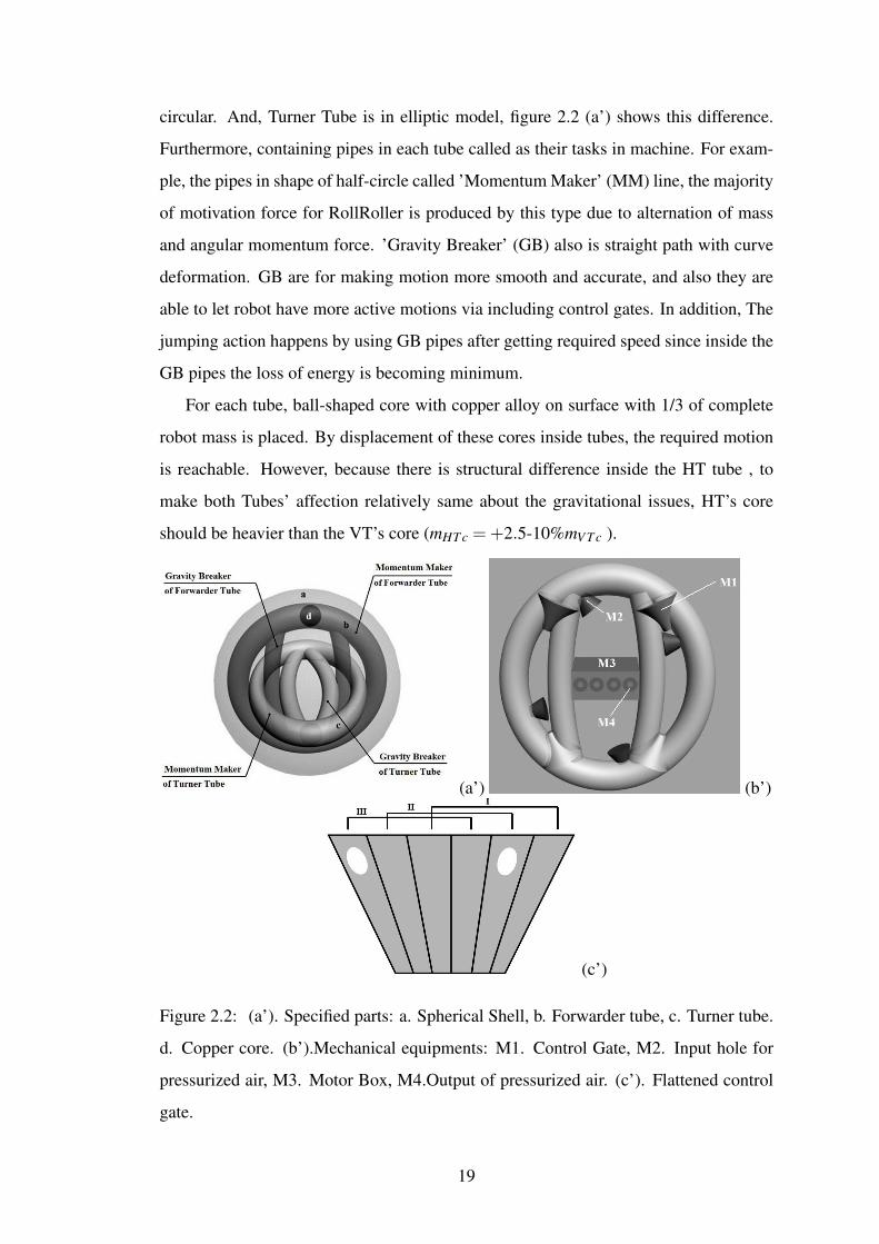
(a’) (b’)
(c’)
Figure 2.2: (a’). Specified parts: a. Spherical Shell, b. Forwarder tube, c. Turner tube.
d. Copper core. (b’).Mechanical equipments: M1. Control Gate, M2. Input hole for
pressurized air, M3. Motor Box, M4.Output of pressurized air. (c’). Flattened control
gate.
19
2.1.2 Mechanical Instruments
For giving corresponded force to copper core, pressurized air is produced by pneumatic
cylinder joined to stepper motor which total part defines the inside driving unit (IDU).
The produced air force enters the tubes with steady magnitude under ideal condition
since there is no leakage and always pressure and air quality inside the tube stay con-
stant. To keep the level of air force constant, the air tank is used to increase/decrease
pressure inside tube when any leakage sensed. However, another main goal is keeping
cores in certain speed hence air actuated force can be vary proportionally. In Figure
2.2 (b’.M3), related actuators are placed inside box and outputs located on box in SMR.
These systems can perform in either suction or injection mode. For each FT and TT two
motors and two cylindrical pneumatic actuators separately are placed in motor boxes.
Each of boxes contain four manual input holes which connected to specific places on
tube as seen in picture. This overall system has got capability of controlling the copper
bar in majority of controlled algorithms . Control gates are located in predefined accu-
rate places around the tube for manipulating the path of copper core via opening and
closing, to act in one of the either functions.
Figure 2.2 (c’) shows the flatten form of pyramid control gates locating in interface
of MM with GB pipes. During function I activation both pipes are closed so any air
movement and possibility of entering the core to other pipes’ area is avoided. Function
II and III keep an either paths (e.g., Momentum maker) open or closed. Not only control
gate behave proportional to place of core and used for changing circulation of air inputs
to tubes but also is playing main role in creating the reaction torque in RollRoller, this
specification will be explained in jumping motion later on. Particularly, when the core
reaches to nearby of gate with constant speed, the gate senses the place of it via position
sensors and then form itself relative to simulation.
2.2 Movements Algorithm
2.2.1 Forward Locomotion
This locomotion section is just providing movement in forward direction (figure 2.3)
in flat terrain without any damp or obstacle. As shown in Figure 2.4, overall tube is
20
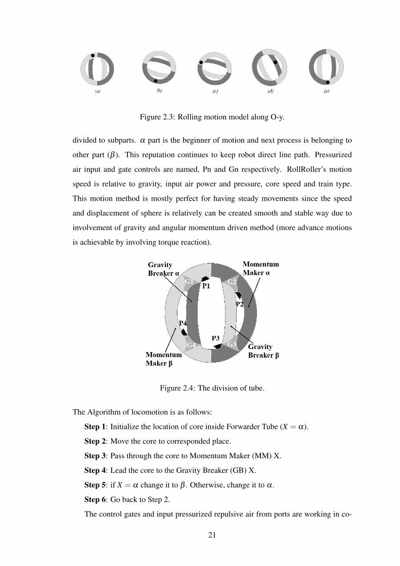
Figure 2.3: Rolling motion model along O-y.
divided to subparts. α part is the beginner of motion and next process is belonging to
other part (β ). This reputation continues to keep robot direct line path. Pressurized
air input and gate controls are named, Pn and Gn respectively. RollRoller’s motion
speed is relative to gravity, input air power and pressure, core speed and train type.
This motion method is mostly perfect for having steady movements since the speed
and displacement of sphere is relatively can be created smooth and stable way due to
involvement of gravity and angular momentum driven method (more advance motions
is achievable by involving torque reaction).
Figure 2.4: The division of tube.
The Algorithm of locomotion is as follows:
Step 1: Initialize the location of core inside Forwarder Tube (X = α).
Step 2: Move the core to corresponded place.
Step 3: Pass through the core to Momentum Maker (MM) X.
Step 4: Lead the core to the Gravity Breaker (GB) X.
Step 5: if X = α change it to β . Otherwise, change it to α .
Step 6: Go back to Step 2.
The control gates and input pressurized repulsive air from ports are working in co-
21

operative way with each other in this process of motion in which for each cycle of
movement, the role of each component is demonstrated on Table 2.1.
Cycle Control Gates Output Ports Core
Mode G1 G2 G3 G4 P1 P2 P3 P4 Location
a I II II I I S O O MM
b I I II II O I S O MM
c II I I II S O I O MM
d II II I I S O I O GB
e II I I II I T S T EP
O= Off, S=Suction in tube, I=Injection in tube, T= Injection/Suction in tube via tank ,
Equilibrium point=EP, GB = Gravity Breaker , MM =Momentum Maker , GB =
Gravity Breaker , MM = Momentum maker .
Table 2.2: FUNCTIONS OF FORWARD MOVEMENT
Avoiding any instability while core is climbing up the sphere to change center of
mass is strongest point of this algorithm and robot, in which almost was such a impos-
sible for most of previous robots. Even more algorithmic steps is in a way that failure in
control method while there is an air inputs change requirement, doesn’t reflects sudden
fluctuations in total robot’s displacement. Lastly, one cycle delay due to friction factors
or imperfect input may just prevent the robot to enter next cycle mode. However, in this
case IMU and gravitational sensors would be involved and let robot to repeat cycle until
the required position is achieved by SMR.
2.2.2 Circular Turning
In this particular movement, the proposed robot (RollRoller) tries to turn on plane via
changing mass center (some minor effects have been avoided which may cause insta-
bility in robot). For circular locomotion, position of cores for producing corresponding
gestures is like Figure 2.5. For simplicity of explanation it is considered that RollRoller
initial form is like first gesture on beginning of left hand-side. Particularly, VT’s core
is located in equilibrium point and HT’s core in MM part. In next Step, robot tries
to maintain its forward movement despite the locomotion of horizontal tube core to
22
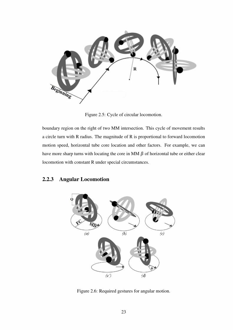
Figure 2.5: Cycle of circular locomotion.
boundary region on the right of two MM intersection. This cycle of movement results
a circle turn with R radius. The magnitude of R is proportional to forward locomotion
motion speed, horizontal tube core location and other factors. For example, we can
have more sharp turns with locating the core in MM β of horizontal tube or either clear
locomotion with constant R under special circumstances.
2.2.3 Angular Locomotion
Figure 2.6: Required gestures for angular motion.
23
This movement is a strong advantage of this robot. By this movement,we are able
locate robot in accurate directions via center of mass diversity with minimum error.
Also, there is no requirement for existence of forward direction motion like in circular
locomotion we had. In contrast, other previous SMRs mostly had to have turning nor-
mally such as previous section. The proposed gestures are demonstrated in Figure 2.6.
As result of having spherical shell, the robot required to operate in area dependent to
radius of tubes, it is showed as fire circle (FC). Main direction (MD) defined as steady
posture. Case a is initial gesture of SMR for beginning of motion. Turner (Horizontal)
tube core moves to right side of robot and rotates it 45o along itself in case b. Then
Forwarder (Vertical) tube has 45o change along Turner tube and goes backward. Even-
tually, for returning the robot to its main gesture, Forwarder and Turner tube’s cores
moves simultaneously as case c. Case c is been demonstrated to give better perspective
about the motion. In same time, VT’s core pass through the GB path. However, the
core in Turner (horizontal) tube moves to momentum maker path. At the end, sphere
will have θ angular change due to main direction. In here Q gives the minimal angular
change respect to radius of VT in sphere but in reality this is much smaller (22.5o > θ )
2.2.4 Slide Locomotion
(a)
(b)
Figure 2.7: Cycle of slide locomotion: (a).Perspective view , (b.) Top view.
This movement shows that RollRoller can move in slide direction without any re-
24

quired turning. Also, this movement takes it corresponding movement force with grav-
ity change hence the possibility of accidental error considerably low. Figure 2.7 case a
shows steps about manner. The algorithm of movement is as follow:
Step 1: Initializing the condition of robot.
Step 2: Movement of Turner Tube core by passing through right Gravity Breaker
(GB) and entering the right Momentum Maker (MM) part.
Step 3: Reaching the core to end of Turner Tube (TT).
Step 4: Forwarder Tube (FT) core moves go through left Momentum Maker (MM)
path and gives the robot displacement.
Step 5: Return to Step 3.
And case (b) shows the movement in clear top view manner. Path I demonstrate as
ideal movement and Path R is our real posture line which O stands for offset of sphere
due to its shape.
2.2.5 Jump Locomotion
This motion demonstrates the other unique specification of RollRoller as 4th DOF. In
this motion we considered the first gesture of robot like previous ones. Then for ini-
tializing the jumping activity, the turner tube core moves to corner of tube (Equilibrium
point) for giving the corresponded gesture as Figure 2.8 (a) in same time Forwarder
Tube (FT) core goes through momentum maker path. Figure 2.8 (b) shows these steps.
(a) (b)
Figure 2.8: Cycle of Angular motion (a).Initial formation. (b) Jumping Operation.
Sphere after initializing the structure as shown in Figure 2.8 (b), cores in same time
moves through Gravity Breaker part and by using the torque reaction, cores meet the
closed gates. Accordingly, total force leads to parabolic jumping path in air by circular
25
turnings. The ’h’ parameter demonstrates the possible height. For giving higher jump
we could add other extra movements like moving cores in momentum maker paths for
increasing the speed of them and then let the event take place.
2.3 Electrical Sensors Overview
We make RollRoller as semi-intelligent robot has sensation about its current position
instructions. Occasional sensors are used for accurate displacement of robot. Sys-
tem electrical controlling diagram is demonstrated in figure 2.9. it uses three effi-
cient sensing material (i.e. Circular sensors, Geometric positioning sensor and gravity
sensor).Geometric positioning (IMU) sensor and gravity sensor are electrical circuits,
whereas Circular sensors is novel sensor specialized for only RollRoller. Main con-
troller IC collect the coming data from sensors for visualizing the current place of core,
current gravity magnitude and the position of robot in 3D plane respect to base. Next,
the motion control data is sent to robot. Pre-defined instruction in main controller IC,
decides the steps. Lastly, motors (pressurized air producer) and gates control works pro-
portional to programmed algorithm. Circular Sensors are semi-physical sensors located
around the tubes for giving the location of relating cores in RollRoller.
Figure 2.9: Diagram of electrical behavior of RollRoller.
Circular Sensor: Circular sensors are semi-physical sensors located around the
tubes for giving the location of related cores in robot. This feature is two parts circular
copper as Fig.2.10, one side polarized with Vcc Voltage and other part connected to IC
port in link with one diode and resistor. Diode has put for preventing of any reverse
26

current from IC port. While copper core passes through this instrument, changing of
voltage from 0 to 1 in corresponded port locate the place of core.
Figure 2.10: Circular sensor.
27

Chapter 3
Mathematical Analysis
3.1 Basic Motion Dynamics Calculations
In this chapter because ”RollRoller” requires serious time and effort to calculate the
practical algorithmic dynamics , only non-algorithmic ordinary dynamics [48] have
been derived, the core just start moving through fixed circular tube to produce motion
via gravitational and angular momentum force. The main reason behind keeping work
as simple as possible is as result of nonholonomic and non-linear structure of spherical
robot that it still is hard and sophisticated way to be derived [49] for general dynamical
formation. As consequence, in this section, by using Euler-Lagrange method dynamics
are found for containing novel model in which it will be seen that still the non-linearity
of system is involved in almost all the variables as coefficient. As seen from the cycle of
locomotion at previous chapter, main produced momentum is just happened in Fig.2.3
case b hence the geometric locomotion is as Fig.2.3 (the effect of case d is neglected
initially).Also, the bellow assumptions are considered during :
I. The ground imagined without any slippery.
II. Homologous components have been used.
III. The shell outside sphere is rigid.
VI. The Turner Tube’s core placed in equilibrium point with balancing the forward
tube in straight direction.
V. The Forwarder Tube’s core positioned on top of tube when the sphere is in statical
equilibrium point.
Reference frames are denoted in which O0−X0Y0Z0 represents the inertial fixed
28

reference. The moving frame connected to the center of sphere is O1−X1Y1Z1, which
translate only with respect to inertial fixed reference. Also, O2− X2Y2Z2 is another
frame attached to center like previous one but it just rotate only with respect to the
O1−X1Y1Z1. (figure 3.1 shows the coordination of each unit vector with axis)
Figure 3.1: Rolling motion geometric model along O-y.
θ Rolling angle of RollRoller around x axis
γ Locomotion angle of the core
g Gravitational acceleration
R Sphere radius
r Distance between the center of the RollRoller and the center of the core
Table 3.1: NOMENCLATURE OF DYNAMIC ANALYSIS
Dpo represents the position vector in the robot. Angular and linear velocity vectors
are ωs and Vs , also angular velocity ωc and linear velocity Vc are relate to core.
Dpo = rsin(γ +θ) j+ rcos(γ +θ)k (3.1)
ωs = θ i (3.2)
Vs = Rθ j (3.3)
ωc = (γ + θ)i (3.4)
29

Figure 3.2: The unit vectors, angular and linear velocities.
Vc = (Rθ +(γ + θ)rcos(γ +θ)) j− ((γ + θ)rsin(γ +θ))k (3.5)
The relation between sphere and core mass is as below:
mc =13
Ms (3.6)
where Ms and mc are the masses of the sphere and core. This property is for empha-
sizing the gravity force in displacement. For reaching the dynamic model of robot, the
Lagrangian function L containing only the terms due to rotation along the O-y axis is
written as follows:
L = Ek−Ep (3.7)
The kinetic energy are mostly produced angular and linear velocities from sphere and
core displacement , angular momentum driven method is satisfied by preserving these
energies. Gravitation energy in core is the related to potential energy (Ep =−mcgdc−z).
In potential energy equation, the remaining distance after substituting the total vertical
axis (z) from the core position gives real potential energy.
L =12
Ms|Vs|2 +12
Is|ωs|2 +12
mc|Vc|2 +12
Ic|ω|2 +mcgdc−z (3.8)
Particularly, for each of sphere and core, there are two main partition:
1- Created energy from object with mass (M) while containing linear velocity.
(12
MV 2)
2- Created angular energy from rotational velocity of object with its own moment
of inertia (I).(12
Iω2s )
30
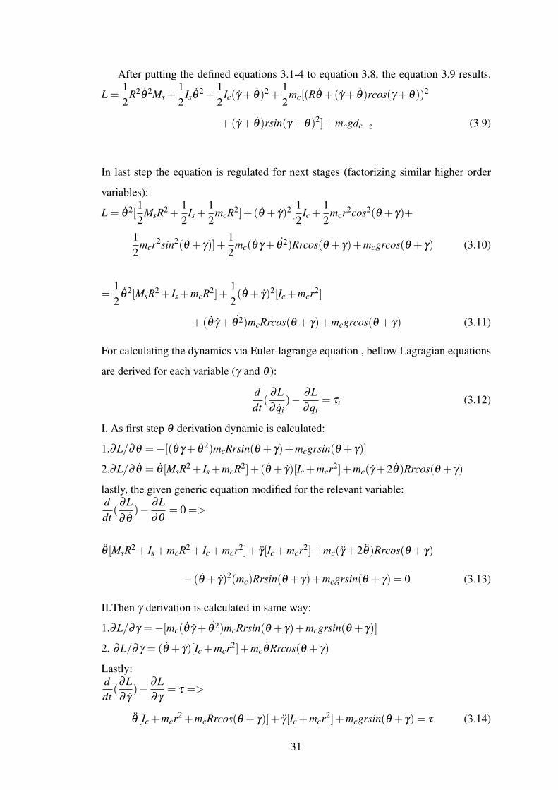
After putting the defined equations 3.1-4 to equation 3.8, the equation 3.9 results.
L =12
R2θ 2Ms +12
Isθ2 +
12
Ic(γ + θ)2 +12
mc[(Rθ +(γ + θ)rcos(γ +θ))2
+(γ + θ)rsin(γ +θ)2]+mcgdc−z (3.9)
In last step the equation is regulated for next stages (factorizing similar higher order
variables):
L = θ 2[12
MsR2 +12
Is +12
mcR2]+ (θ + γ)2[12
Ic +12
mcr2cos2(θ + γ)+
12
mcr2sin2(θ + γ)]+12
mc(θ γ + θ 2)Rrcos(θ + γ)+mcgrcos(θ + γ) (3.10)
=12
θ 2[MsR2 + Is +mcR2]+12(θ + γ)2[Ic +mcr2]
+ (θ γ + θ 2)mcRrcos(θ + γ)+mcgrcos(θ + γ) (3.11)
For calculating the dynamics via Euler-lagrange equation , bellow Lagragian equations
are derived for each variable (γ and θ ):
ddt(
∂L∂ qi
)− ∂L∂qi
= τi (3.12)
I. As first step θ derivation dynamic is calculated:
1.∂L/∂θ =−[(θ γ + θ 2)mcRrsin(θ + γ)+mcgrsin(θ + γ)]
2.∂L/∂ θ = θ [MsR2 + Is +mcR2]+ (θ + γ)[Ic +mcr2]+mc(γ +2θ)Rrcos(θ + γ)
lastly, the given generic equation modified for the relevant variable:ddt(
∂L∂ θ
)− ∂L∂θ
= 0 =>
θ [MsR2 + Is +mcR2 + Ic +mcr2]+ γ[Ic +mcr2]+mc(γ +2θ)Rrcos(θ + γ)
− (θ + γ)2(mc)Rrsin(θ + γ)+mcgrsin(θ + γ) = 0 (3.13)
II.Then γ derivation is calculated in same way:
1.∂L/∂γ =−[mc(θ γ + θ 2)mcRrsin(θ + γ)+mcgrsin(θ + γ)]
2. ∂L/∂ γ = (θ + γ)[Ic +mcr2]+mcθRrcos(θ + γ)
Lastly:ddt(∂L∂ γ
)− ∂L∂γ
= τ =>
θ [Ic +mcr2 +mcRrcos(θ + γ)]+ γ[Ic +mcr2]+mcgrsin(θ + γ) = τ (3.14)
31

Input torque (τ) in equation 3.13 is zero since there is no reaction force relative to
sphere ( e.g. in pendulum models this value exists with negative sign τ [48]). On the
other hand, the input in equation 3.14 is series of air pulses generated by pneumatic
cylinders.
”RollRoller”’s compact form of motion equation can be shown as beneath matrix
form: M11 M12
M21 M22
θ
γ
+
N11
N21
+
G11
G21
=
0
τ
(3.15)
M11 = MsR2 + Is +mcR2 + Ic +mcr2 +2mcRrcos(θ + γ)
M12 = M21 = Ic +mcr2 +mcRrcos(θ + γ) , M22 = Ic +mcr2
N11 =−(θ + γ)2(mc)Rrsin(θ + γ) , N21 = 0 , G11 = G22 = mcgrsin(θ + γ).
Although, this matrix form may not give reliable clues about the role of each com-
ponent on creation of RollRoller’s locomotion, the N11 coefficient can guessed as main
swinging part. In particular, the ”(θ + γ)2” part gives parabolic raise and the ”sin(θ +
γ)” part represents the sinusoidal swinging around this parabolic increase. For the
sphere this value is zero (N21). The other coefficients that get involved in ’M’ array vari-
ables are mostly constant or have considerable small effect on system manner. Lastly,
’G’ represents gravitational factors for both dynamical equations.
To Make State-space form simulation results on Matlab, The equations are com-
pacted by defined variables.
a)
θ [A]+ γ[B]− (θ + γ)2(mc)Rrsin(θ + γ)+mcgrsin(θ + γ) = 0 (3.16)
b)
θ [B]+ γ[D]+mcgrsin(θ + γ) = τ (3.17)
Definitions:
A = MsR2 + Is +mcR2 + Ic +mcr2 +2mcRrcos(θ + γ) = a+2bcos(θ + γ)
B = Ic +mcr2 +mcRrcos(θ + γ) = D+bcos(θ + γ)
C = (θ + γ)2
b = mcRr
a = MsR2 + Is +mcR2 + Ic +mcr2
32
D = Ic +mcr2
h = mcgr
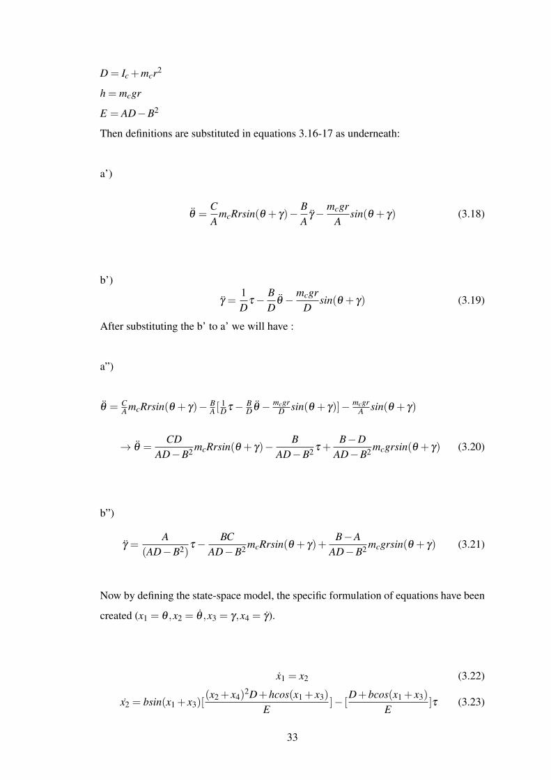
E = AD−B2
Then definitions are substituted in equations 3.16-17 as underneath:
a’)
θ =CA
mcRrsin(θ + γ)− BA
γ− mcgrA
sin(θ + γ) (3.18)
b’)
γ =1D
τ− BD
θ − mcgrD
sin(θ + γ) (3.19)
After substituting the b’ to a’ we will have :
a”)
θ = CA mcRrsin(θ + γ)− B
A [1Dτ− B
D θ − mcgrD sin(θ + γ)]− mcgr
A sin(θ + γ)
→ θ =CD
AD−B2 mcRrsin(θ + γ)− BAD−B2 τ +
B−DAD−B2 mcgrsin(θ + γ) (3.20)
b”)
γ =A
(AD−B2)τ− BC
AD−B2 mcRrsin(θ + γ)+B−A
AD−B2 mcgrsin(θ + γ) (3.21)
Now by defining the state-space model, the specific formulation of equations have been
created (x1 = θ ,x2 = θ ,x3 = γ,x4 = γ).
x1 = x2 (3.22)
x2 = bsin(x1 + x3)[(x2 + x4)
2D+hcos(x1 + x3)
E]− [
D+bcos(x1 + x3)
E]τ (3.23)
33

x3 = x4 (3.24)
x4 =−sin(x1 + x3)[((b(x2 + x4)
2(D+bcos(x1 + x3)))+((a−D)+bcos(x1 + x3))h)E
]
+ [a+2bcos(x1 + x3)
E]τ (3.25)
As mentioned before, it is obvious even though we find out the homogeneous and basic
dynamic of SMR (without using any Euler-Jacobi-Lie theorem [49]), the equations are
taking the form of nonlinear (e.g. square functions and sinusoidal sums, multiplications
and division).
3.2 Fractional Motion Dynamics
The previous dynamic calculation were for just only to validate robots, following known
trajectory to make its main motion. In this part, to make motion more realistic the vis-
cous friction between core, sphere and ground has been involved. The energy dissipa-
tion function is relative to damping constant and system’s velocity. This will help us to
understand robot better how reacts to initial steps. The definition of equation is as:
P =12
ζ (θ + γ) (3.26)
Hence the Lagrange-Euler equation will be updated as bellow formula:
ddt(
∂L∂ qi
)− ∂L∂qi
+∂P∂ qi
= τi (3.27)
Next, the dynamical equations are updated (∂P∂ θi
= ζ θ and∂P∂ γi
= ζ γ):
a)
θ [MsR2 + Is +mcR2 + Ic +mcr2]+ γ[Ic +mcr2]+mc(γ +2θ)Rrcos(θ + γ)
− (θ + γ)2(mc)Rrsin(θ + γ)+mcgrsin(θ + γ)+ζ θ = 0 (3.28)
b)
θ [Ic +mcr2 +mcRrcos(θ + γ)]+ γ[Ic +mcr2]+mcgrsin(θ + γ)+ζ γ = τ (3.29)
And matrix compact form is been changed. M11 M12
M21 M22
θ
γ
+
N11
N21
+
G11
G21
=
0
τ
(3.30)
34
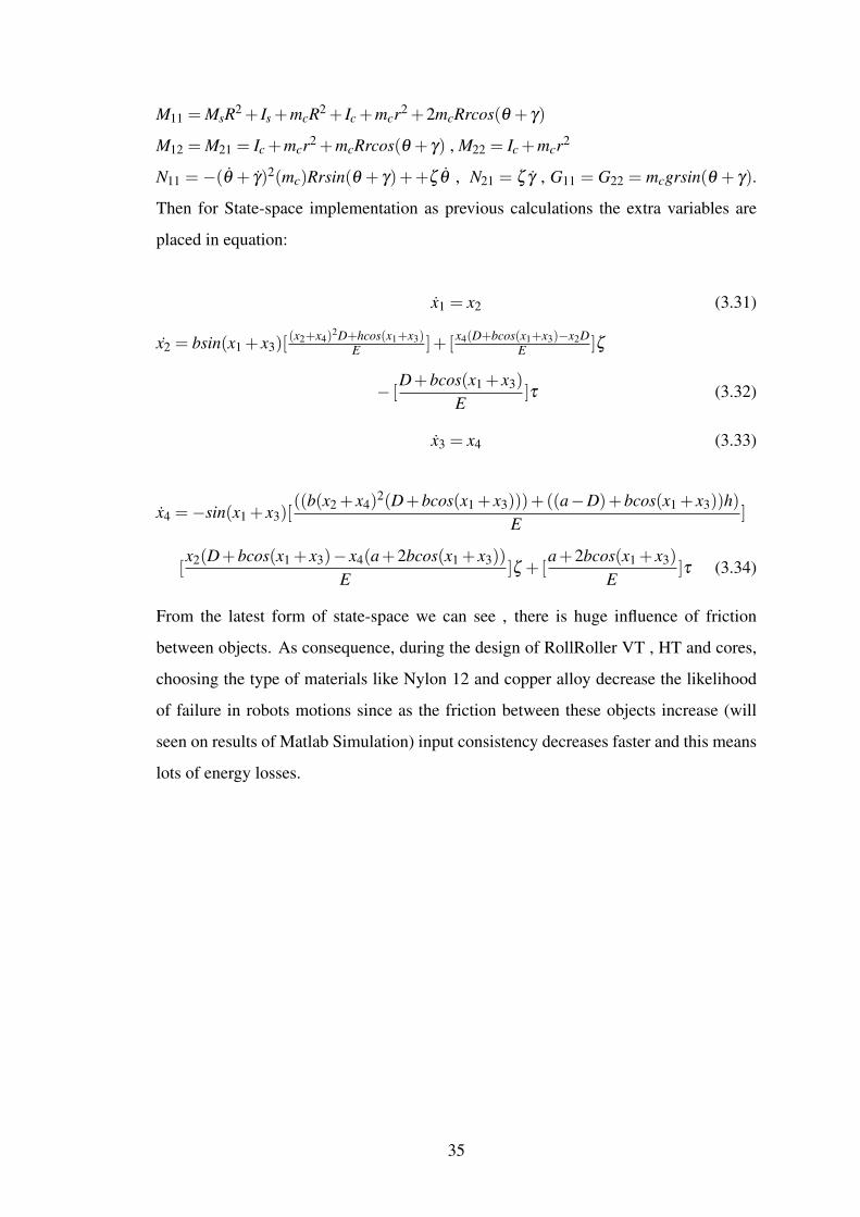
M11 = MsR2 + Is +mcR2 + Ic +mcr2 +2mcRrcos(θ + γ)
M12 = M21 = Ic +mcr2 +mcRrcos(θ + γ) , M22 = Ic +mcr2
N11 = −(θ + γ)2(mc)Rrsin(θ + γ)++ζ θ , N21 = ζ γ , G11 = G22 = mcgrsin(θ + γ).
Then for State-space implementation as previous calculations the extra variables are
placed in equation:
x1 = x2 (3.31)
x2 = bsin(x1 + x3)[(x2+x4)
2D+hcos(x1+x3)E ]+ [x4(D+bcos(x1+x3)−x2D
E ]ζ
− [D+bcos(x1 + x3)
E]τ (3.32)
x3 = x4 (3.33)
x4 =−sin(x1 + x3)[((b(x2 + x4)
2(D+bcos(x1 + x3)))+((a−D)+bcos(x1 + x3))h)E
]
[x2(D+bcos(x1 + x3)− x4(a+2bcos(x1 + x3))
E]ζ +[
a+2bcos(x1 + x3)
E]τ (3.34)
From the latest form of state-space we can see , there is huge influence of friction
between objects. As consequence, during the design of RollRoller VT , HT and cores,
choosing the type of materials like Nylon 12 and copper alloy decrease the likelihood
of failure in robots motions since as the friction between these objects increase (will
seen on results of Matlab Simulation) input consistency decreases faster and this means
lots of energy losses.
35
Chapter 4
Visualization Results And Simulink
4.1 Matlab Simulink
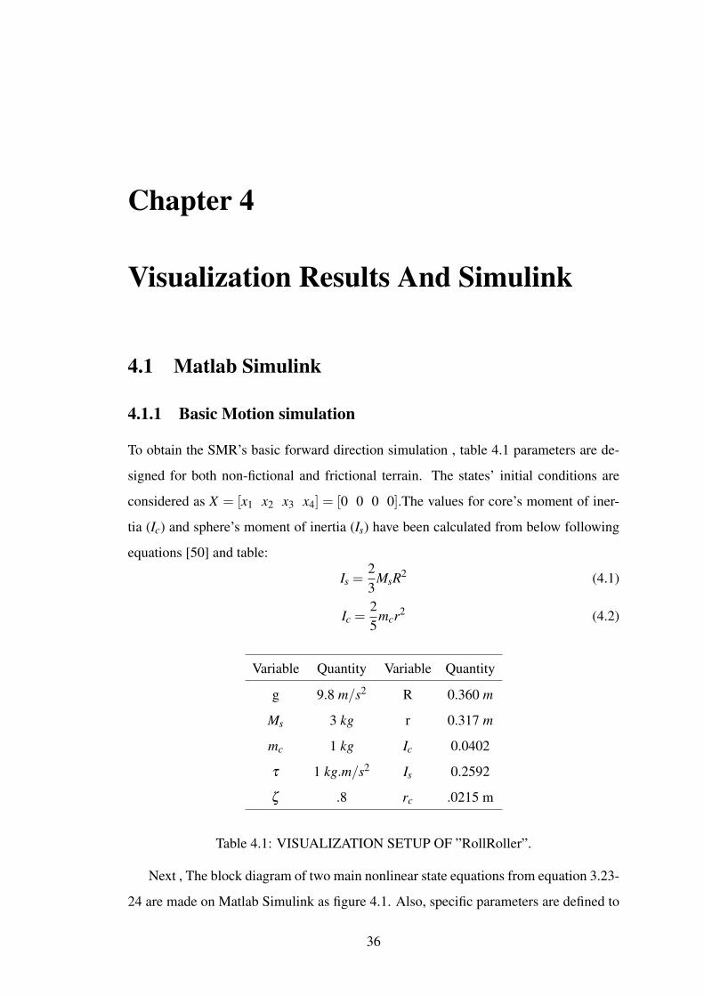
4.1.1 Basic Motion simulation
To obtain the SMR’s basic forward direction simulation , table 4.1 parameters are de-
signed for both non-fictional and frictional terrain. The states’ initial conditions are
considered as X = [x1 x2 x3 x4] = [0 0 0 0].The values for core’s moment of iner-
tia (Ic) and sphere’s moment of inertia (Is) have been calculated from below following
equations [50] and table:
Is =23
MsR2 (4.1)
Ic =25
mcr2 (4.2)
Variable Quantity Variable Quantity
g 9.8 m/s2 R 0.360 m
Ms 3 kg r 0.317 m
mc 1 kg Ic 0.0402
τ 1 kg.m/s2 Is 0.2592
ζ .8 rc .0215 m
Table 4.1: VISUALIZATION SETUP OF ”RollRoller”.
Next , The block diagram of two main nonlinear state equations from equation 3.23-
24 are made on Matlab Simulink as figure 4.1. Also, specific parameters are defined to
36
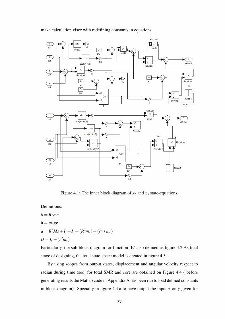
make calculation visor with redefining constants in equations.
Figure 4.1: The inner block diagram of x2 and x3 state-equations.
Definitions:
b = Rrmc
h = mcgr
a = R2Ms+ Is + Ic +(R2mc)+(r2 ∗mc)
D = Ic +(r2mc)
Particularly, the sub-block diagram for function ’E’ also defined as figure 4.2.As final
stage of designing, the total state-space model is created in figure 4.3.
By using scopes from output states, displacement and angular velocity respect to
radian during time (sec) for total SMR and core are obtained on Figure 4.4 ( before
generating results the Matlab code in Appendix A has been run to load defined constants
in block diagram). Specially in figure 4.4.a to have output the input τ only given for
37

Figure 4.2: Block diagram of function E.
Figure 4.3: Generic block diagram of state-space model.
just 1 sec as step pulse input ( Figure 4.5) then the core starts moving through the pipe
from predefined initial location as figure 2.3 a in section 2.2.1.
Swinging in displacement of core is reflecting the physical characteristic of the cir-
cular tube that it just stays in constant amplitude range. The total sphere via gaining
force from angular momentum and gravity let the central mass be diverse during pro-
cess, begins to move the sphere in direct path. Because the robot contains simple mech-
anism the requirement of serious control methods are avoided. RollRoller doesn’t have
any serious fluctuation in it’s displacement ,although main algorithm including Grav-
ity Breakers, haven’t been implemented to have more smooth and damped movement.
Figure 4.4.b demonstrates velocity of core and sphere. Both velocities shifted propor-
38

(a)
(b)
Figure 4.4: (a). Displacement of core and sphere (b). Velocity for both core and sphere.
Figure 4.5: Pulse input to system (τ).
39

(a)
(b)
Figure 4.6: (a). Velocity response of sphere and core states with double pulse input to
system (2τ) (b). Velocity response of sphere and core states with higher pulse input to
system (6τ)
tional to input torque (τ = 1N.m). As a point, it is understandable from results, velocity
relation of core with sphere is somehow beneficial but there is sinusoidal fluctuation in
velocity of sphere which will be sorted out by algorithm in section 2.2.1 as said. Fur-
thermore, the downhill amplitude of sphere’s speed is almost 10% of uphill. This is
mathematical proof for direct path movement due to speed results.
On the other hand, the velocity graph tells us by increasing the speed of core the total
SMR just gets the small amount of that angular momentum fluctuation. To validate this
prediction, the value of input torque (τ) was increased to 2 N.m. The speed of core
and sphere achieved acceptably as expected in figure 4.6 a. In the graph, scheme after
shifting the SMR’s speed to around the 2-2.2 rad/s, the value of each uphill downhill
is approximately same as the results from τ = 1 (Aτ=1 = Aτ=2 = .8 uphill and Aτ=1 =
Aτ=2 = .2 downhill ). Nevertheless, without using proposed algorithm this results will
look acceptable until certain level of input. When torque limitation exceed , sphere will
40

contain waving manner ( Figure 4.6 b). Figure 4.6 b explains this result with having
τ = 6 N.m input. Eventually, this subsection validate the results about basic clear
locomotion of sphere.
4.1.2 Simulation of Motion with Fraction
Figure 4.7: The inner updated block diagram of x2 and x4 state-space models.
41

A few minor changes have taken place in this simulation, for instance the x2 and
x4 block diagrams were updated by extra variables as equations 3.32 and 3.34. The
enhanced parts in x2 and x4 block diagrams from figure 4.1 are represented on figure
4.7 ( The orange circled parts are the updated parts to simulation). Clearly, the friction
parts have influence directly to all the states,it means more the friction goes up, the
convergence happens faster. As consequence, friction must be balanced in system as
reflects the main reason behind using Nylon 12-copper viscosity value. Although, the
viscosity of this value is about .63, it is considered .8 to see results in worst conditional
environment.
Figure 4.8: (a). Displacement of core and sphere with friction (b). Velocity for both
core and sphere with friction.
The results are illustrated on figure 4.8. The movement of sphere and core shows
that the core ( dashed line) due to initial input force starts moving through tube. Next,
By passing through MM (e.g. α as figure 2.4 ) it entered to next MM ( e.g. the opposite
pipe β ). Thus , because of viscous friction in surfaces the core motion damped and
it stopped in middle of MM α tube, figure 2.3 (b) shows it. The perfect minor step
42

displacement in sphere is demonstrated on figure 4.8 (a). By looking at the results,
we can conclude that this robot can have acceptable performance without any complex
control methods. In next graph 4.8 (b) the velocity of core increased as result of 1 sec
pulse input, then it has changed direction corresponding to turning in tube and lastly
died to zero. About the sphere the issue is a little different, although it takes the positive
velocity until assistance of input (1 sec) and core motion , it has sudden decrease (
approximately 0.1-.2) as next phenomenon. And lastly, it reaches to zero after 3 sec.
Again with having look to the results , it is obvious that the proposed morphology
for our design is completely logical and implementable on practice. Following given
trajectory is confirmation of true results about mathematical part.
4.2 Adams/View Numerical Simulation
4.2.1 Direct Generic Motion
To obtain the numerical simulation of ”RollRoller” in forward direction motion on
Adams/View , firstly the model of ”RollRoller” designed on SolidWorks [51] (Figure
4.9). Particularly, in designing process the type of material (e.i. Nylon 101) and center
of mass of total object are highlighted tasks having serious contribution in simulation
procedure. And at end, some required parts was created on Adams/View program itself
to improve the simulation, figure 4.9 shows the latest model of SMR. In this design,
because giving required input air force of core to have movement inside the tube was
so sophisticated and imperfect hence problem has been redirected with giving the force
with another core physically. In other words, turning the pendulum-like object con-
nected to beams from both sides of spherical shell (The yellow part in figure 4.11).Par-
ticularly, this part is lack of any weight or friction toward any main parts (e.g. Sphere,
tube and Core) pushing the main core with another imaginary core. Before starting
main simulation, several tasks have been followed [52]:
1. Plane ground was drawn with opposed y axis gravitation and locked to main ground.
2.The designed assembled parts were imported to Adams/view.
2.a. HT’s GB and MM pipes were locked to each other (as figure 4.10 a ). In this
designing procedure, the required parts are chosen and typology of is chosen as fixed.
2.b. VT’s GB and MM pipes were locked to each other.
43

Figure 4.9: Solidworks Design (Inches Unit).
2.c. VT was locked to spherical shell.
2.d. Due to problematic simulation results in plastic density implementation the
material in simulation considered as glass (Density = 2595 kgm3 ) for HT and VT pipes
(Figure 4.10 c).
3. The core and pendulum actuator were designed.
3.a. Mass of pendulum’s each part considered 0.1451268544.
3.b. Joint Connection was made between pendulum and was linked beams to Sphere
(Figure 4.10 b).
3.c. Torque was defined for designed pendulum as figure 4.10 d( T =−25N.m ).
3.d. The core was designed with r = 2.85 cm, mc =13Ms = 15 kg and with tungsten
material ( Density = 1.9e+004 kgm3 ) .
3.e. The relation between core and VT pipes was created. ( Sti f f ness = 1.0e+
006N.Mrad , Damping = 1.0e+005 and PD = 1.0e−004).
44
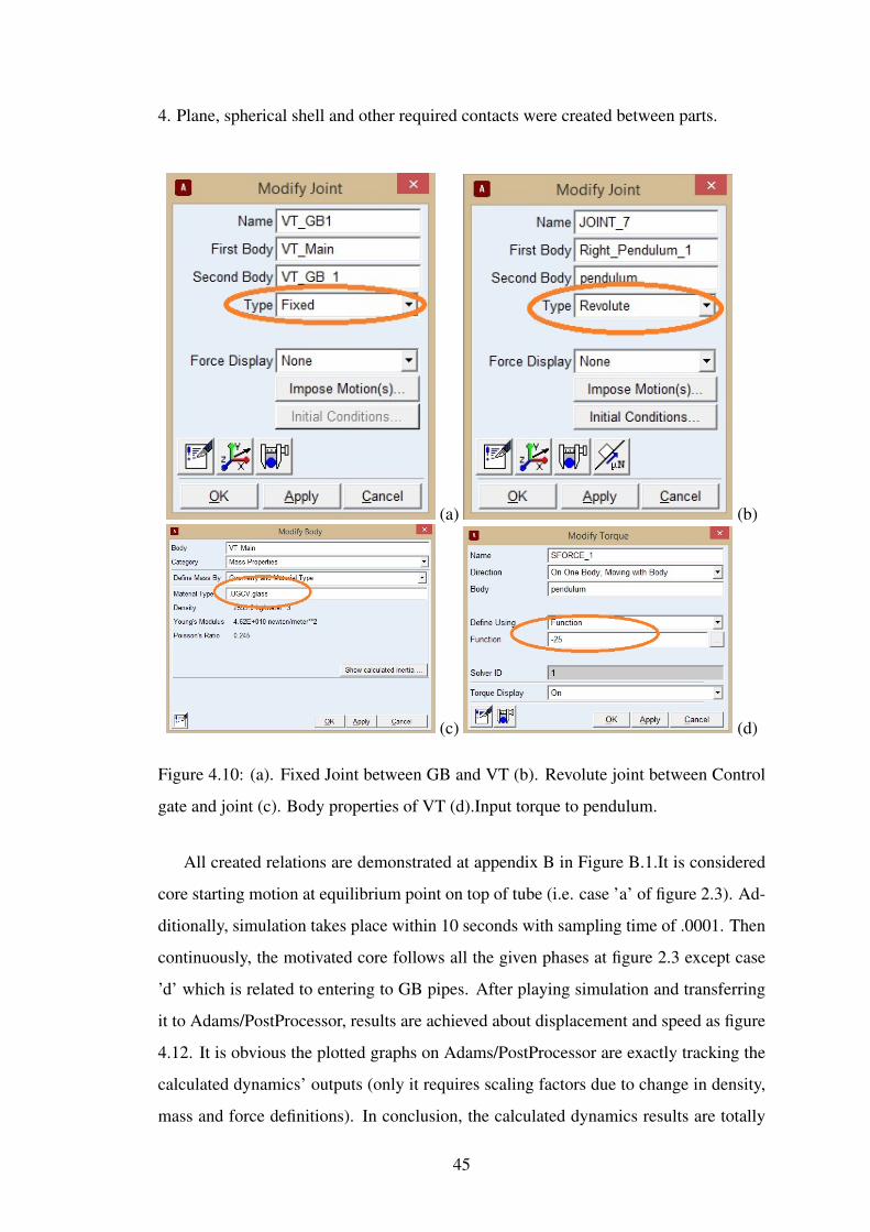
4. Plane, spherical shell and other required contacts were created between parts.
(a) (b)
(c) (d)
Figure 4.10: (a). Fixed Joint between GB and VT (b). Revolute joint between Control
gate and joint (c). Body properties of VT (d).Input torque to pendulum.
All created relations are demonstrated at appendix B in Figure B.1.It is considered
core starting motion at equilibrium point on top of tube (i.e. case ’a’ of figure 2.3). Ad-
ditionally, simulation takes place within 10 seconds with sampling time of .0001. Then
continuously, the motivated core follows all the given phases at figure 2.3 except case
’d’ which is related to entering to GB pipes. After playing simulation and transferring
it to Adams/PostProcessor, results are achieved about displacement and speed as figure
4.12. It is obvious the plotted graphs on Adams/PostProcessor are exactly tracking the
calculated dynamics’ outputs (only it requires scaling factors due to change in density,
mass and force definitions). In conclusion, the calculated dynamics results are totally
45

converging the visualized robots outputs.
Figure 4.11: RollRoller’s Adams/view simulation design.
(a)
(b)
Figure 4.12: (a). Displacement of core and sphere result on Adams/PostProcessor (b).
Velocity for both core and sphere result on Adams/PostProcessor.
Because the translation momentum in Y axis is one of essential parameters in giving
motion to robot, the figure 4.13 illustrated about the results for sphere during this inter-
val. As obvious from the output in this sense, although our basic motion was perfectly
satisfying , the robot suffering from keeping its angular momentum in conservative
46

mode since there is loss from jumping ups and downs of sphere (Figure 4.13). There
are two main reasons for this phenomena, numerical errors that took place during sim-
ulation and imperfect motion algorithm. Nevertheless, by using main algorithm motion
(figure 2.3) it is able to be sorted out because it rectifies sinusoidal behavior to more
linear form, this characteristic will put under scope later on. In addition to that, this
mechanism will result more rectified motion and velocity for SMR. (e.g. pendulum
structured models). Another strong point of RollRoller is increasing angular acceler-
Figure 4.13: The translational momentum and displacement in Y axis.
ation as Figure 4.14. The angular acceleration around z axis demonstrating that it is
able to gather speed in which for most of it’s own type was impossible due to high
likelihood of instability in IDU and total SMR motion hence they mostly developed in
constant speed. For examples, as explained in introduction part, many driving meth-
ods with previously defined mechanisms, specially pendulum mechanism were not able
to gain higher speed and they have speed and acceleration limits as center of mass is
primarily located in connected weights (Figure 1.7 b and 1.8). And if actuator of IDU
required to produce the higher speed during motion, it has to move its center of mass in
circular path, and it will cause motor to be unable to control, while it is located in half
upper surface of sphere. As result, it will cause robot to have unpredictable and unstable
manners. This shows the power point of ”RollRoller” novel mechanism. accordingly,
proposed SMR mechanism structure can relocate the center of mass inside pipes with
linear and minimum energy requirements.
47

Figure 4.14: The angular acceleration of total magnitude and Z axis.
4.2.2 Algorithmic Forward Direction Motion
In this subsection, after explaining the basic proposed novel mechanism and validating
via previous simulation results. Time comes to modify the RollRoller’s own motion
results by letting robot follows the main created algorithm on section 2.2.1. To create
required numerical simulation bellow deeds are added to previously existed model.
I) Gates are designed and placed as figure 4.15. Designing real implementable gate
controllers in figure 2.2.(c’) were time consuming process so the more simplified one
with same functionality is created. In this model, Locks has duty to stop the gate in
required locations. And there is joint connecting the gate with sphere’s body. Further-
more, the gate functions in either II or III that let core pass from one path only. In this
simulation due to previous analysis in forward motion(reverse has same structural man-
ner), only two gates controller are used ( mass of gate , joint and locks are considered
small MGC = 1.0e−009 not to effect motion). Also, the functioning code of each gates
has been written as underneath:
FirstGateFunction =−2∗ (ST EP(Time,0.001,0.95, .002,1)
− (2∗ST EP(Time,1.55,0,1.55001,1))) (4.3)
SecondGateFuncton = 2∗ (ST EP(Time,0.001,0.95, .002,1)
− (2∗ST EP(Time,1.3,0,1.3001,1))) (4.4)
In this operator equation, the standard step parameters are ST EP(x,x0,h0,x1,h1).
Particularly, the x as time variable for this coding is defined. Consequently, x0 and x1 are
48
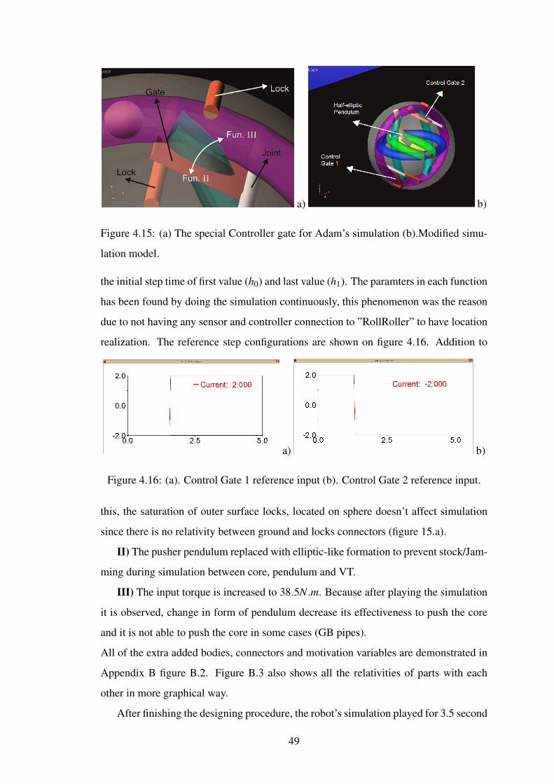
a) b)
Figure 4.15: (a) The special Controller gate for Adam’s simulation (b).Modified simu-
lation model.
the initial step time of first value (h0) and last value (h1). The paramters in each function
has been found by doing the simulation continuously, this phenomenon was the reason
due to not having any sensor and controller connection to ”RollRoller” to have location
realization. The reference step configurations are shown on figure 4.16. Addition to
a) b)
Figure 4.16: (a). Control Gate 1 reference input (b). Control Gate 2 reference input.
this, the saturation of outer surface locks, located on sphere doesn’t affect simulation
since there is no relativity between ground and locks connectors (figure 15.a).
II) The pusher pendulum replaced with elliptic-like formation to prevent stock/Jam-
ming during simulation between core, pendulum and VT.
III) The input torque is increased to 38.5N.m. Because after playing the simulation
it is observed, change in form of pendulum decrease its effectiveness to push the core
and it is not able to push the core in some cases (GB pipes).
All of the extra added bodies, connectors and motivation variables are demonstrated in
Appendix B figure B.2. Figure B.3 also shows all the relativities of parts with each
other in more graphical way.
After finishing the designing procedure, the robot’s simulation played for 3.5 second
49
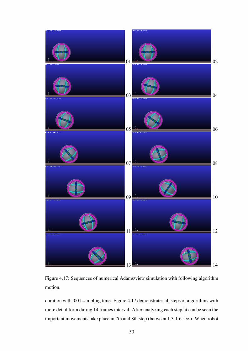
01 02
03 04
05 06
07 08
09 10
11 12
13 14
Figure 4.17: Sequences of numerical Adams/view simulation with following algorithm
motion.
duration with .001 sampling time. Figure 4.17 demonstrates all steps of algorithms with
more detail form during 14 frames interval. After analyzing each step, it can be seen the
important movements take place in 7th and 8th step (between 1.3-1.6 sec.). When robot
50
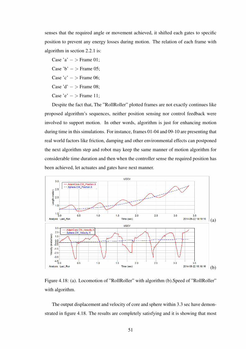
senses that the required angle or movement achieved, it shifted each gates to specific
position to prevent any energy losses during motion. The relation of each frame with
algorithm in section 2.2.1 is:
Case ’a’ −> Frame 01;
Case ’b’ −> Frame 05;
Case ’c’ −> Frame 06;
Case ’d’ −> Frame 08;
Case ’e’ −> Frame 11;
Despite the fact that, The ”RollRoller” plotted frames are not exactly continues like
proposed algorithm’s sequences, neither position sensing nor control feedback were
involved to support motion. In other words, algorithm is just for enhancing motion
during time in this simulations. For instance, frames 01-04 and 09-10 are presenting that
real world factors like friction, damping and other environmental effects can postponed
the next algorithm step and robot may keep the same manner of motion algorithm for
considerable time duration and then when the controller sense the required position has
been achieved, let actuates and gates have next manner.
(a)
(b)
Figure 4.18: (a). Locomotion of ”RollRoller” with algorithm (b).Speed of ”RollRoller”
with algorithm.
The output displacement and velocity of core and sphere within 3.3 sec have demon-
strated in figure 4.18. The results are completely satisfying and it is showing that most
51
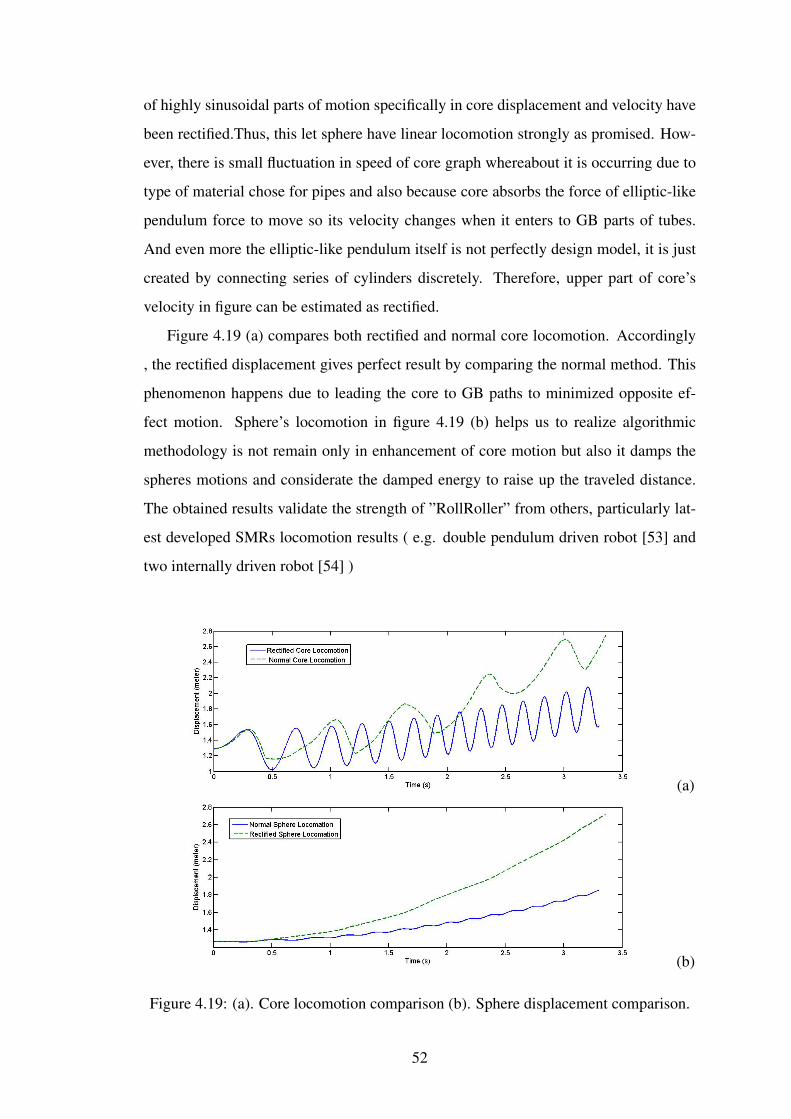
of highly sinusoidal parts of motion specifically in core displacement and velocity have
been rectified.Thus, this let sphere have linear locomotion strongly as promised. How-
ever, there is small fluctuation in speed of core graph whereabout it is occurring due to
type of material chose for pipes and also because core absorbs the force of elliptic-like
pendulum force to move so its velocity changes when it enters to GB parts of tubes.
And even more the elliptic-like pendulum itself is not perfectly design model, it is just
created by connecting series of cylinders discretely. Therefore, upper part of core’s
velocity in figure can be estimated as rectified.
Figure 4.19 (a) compares both rectified and normal core locomotion. Accordingly
, the rectified displacement gives perfect result by comparing the normal method. This
phenomenon happens due to leading the core to GB paths to minimized opposite ef-
fect motion. Sphere’s locomotion in figure 4.19 (b) helps us to realize algorithmic
methodology is not remain only in enhancement of core motion but also it damps the
spheres motions and considerate the damped energy to raise up the traveled distance.
The obtained results validate the strength of ”RollRoller” from others, particularly lat-
est developed SMRs locomotion results ( e.g. double pendulum driven robot [53] and
two internally driven robot [54] )
(a)
(b)
Figure 4.19: (a). Core locomotion comparison (b). Sphere displacement comparison.
52
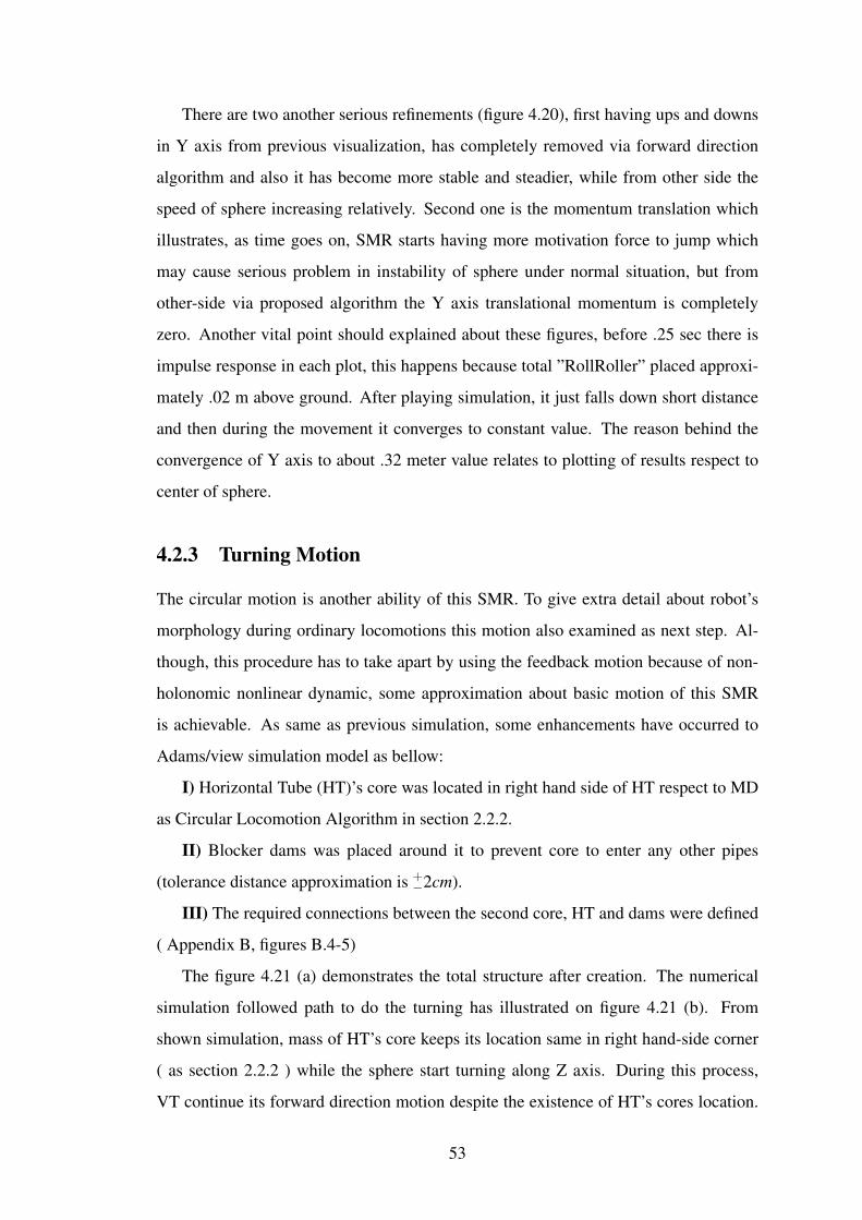
There are two another serious refinements (figure 4.20), first having ups and downs
in Y axis from previous visualization, has completely removed via forward direction
algorithm and also it has become more stable and steadier, while from other side the
speed of sphere increasing relatively. Second one is the momentum translation which
illustrates, as time goes on, SMR starts having more motivation force to jump which
may cause serious problem in instability of sphere under normal situation, but from
other-side via proposed algorithm the Y axis translational momentum is completely
zero. Another vital point should explained about these figures, before .25 sec there is
impulse response in each plot, this happens because total ”RollRoller” placed approxi-
mately .02 m above ground. After playing simulation, it just falls down short distance
and then during the movement it converges to constant value. The reason behind the
convergence of Y axis to about .32 meter value relates to plotting of results respect to
center of sphere.
4.2.3 Turning Motion
The circular motion is another ability of this SMR. To give extra detail about robot’s
morphology during ordinary locomotions this motion also examined as next step. Al-
though, this procedure has to take apart by using the feedback motion because of non-
holonomic nonlinear dynamic, some approximation about basic motion of this SMR
is achievable. As same as previous simulation, some enhancements have occurred to
Adams/view simulation model as bellow:
I) Horizontal Tube (HT)’s core was located in right hand side of HT respect to MD
as Circular Locomotion Algorithm in section 2.2.2.
II) Blocker dams was placed around it to prevent core to enter any other pipes
(tolerance distance approximation is +−2cm).
III) The required connections between the second core, HT and dams were defined
( Appendix B, figures B.4-5)
The figure 4.21 (a) demonstrates the total structure after creation. The numerical
simulation followed path to do the turning has illustrated on figure 4.21 (b). From
shown simulation, mass of HT’s core keeps its location same in right hand-side corner
( as section 2.2.2 ) while the sphere start turning along Z axis. During this process,
VT continue its forward direction motion despite the existence of HT’s cores location.
53
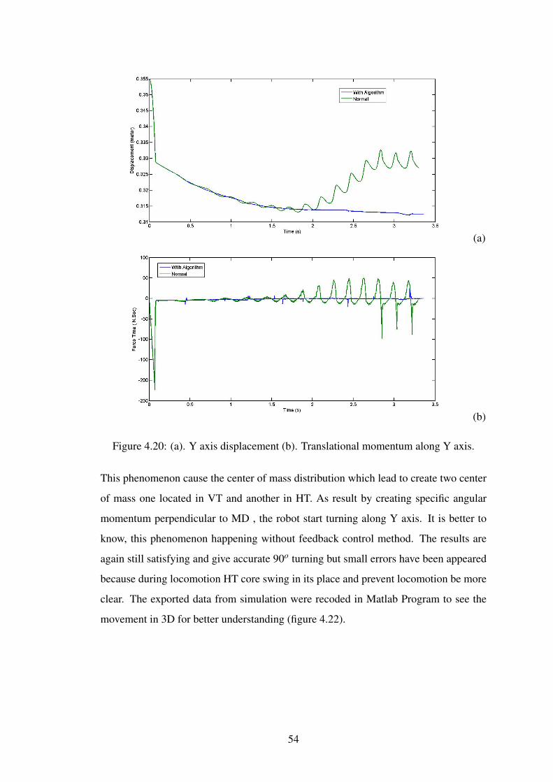
(a)
(b)
Figure 4.20: (a). Y axis displacement (b). Translational momentum along Y axis.
This phenomenon cause the center of mass distribution which lead to create two center
of mass one located in VT and another in HT. As result by creating specific angular
momentum perpendicular to MD , the robot start turning along Y axis. It is better to
know, this phenomenon happening without feedback control method. The results are
again still satisfying and give accurate 90o turning but small errors have been appeared
because during locomotion HT core swing in its place and prevent locomotion be more
clear. The exported data from simulation were recoded in Matlab Program to see the
movement in 3D for better understanding (figure 4.22).
54
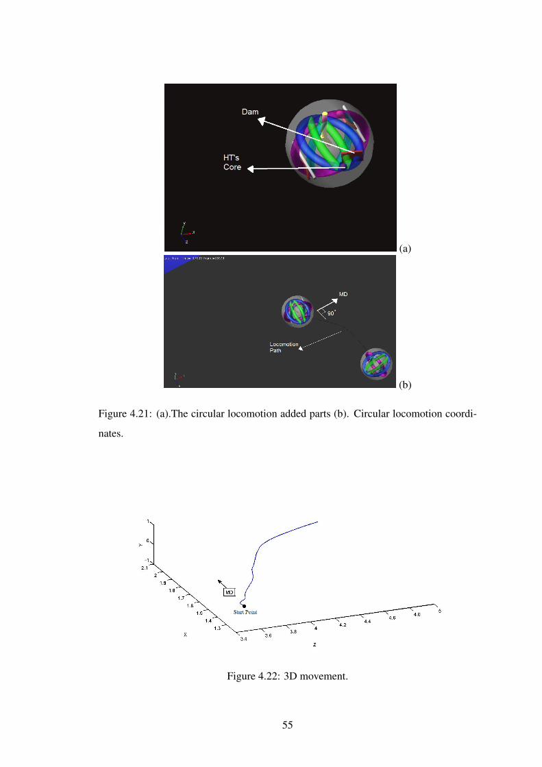
(a)
(b)
Figure 4.21: (a).The circular locomotion added parts (b). Circular locomotion coordi-
nates.
Figure 4.22: 3D movement.
55
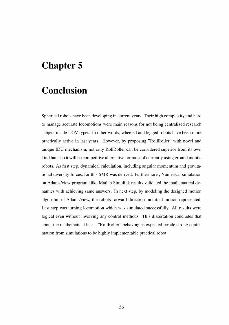
Chapter 5
Conclusion
Spherical robots have been developing in current years. Their high complexity and hard
to manage accurate locomotions were main reasons for not being centralized research
subject inside UGV types. In other words, wheeled and legged robots have been more
practically active in last years. However, by proposing ”RollRoller” with novel and
unique IDU mechanism, not only RollRoller can be considered superior from its own
kind but also it will be competitive alternative for most of currently using ground mobile
robots. As first step, dynamical calculation, including angular momentum and gravita-
tional diversity forces, for this SMR was derived. Furthermore , Numerical simulation
on Adams/view program alike Matlab Simulink results validated the mathematical dy-
namics with achieving same answers. In next step, by modeling the designed motion
algorithm in Adams/view, the robots forward direction modified motion represented.
Last step was turning locomotion which was simulated successfully. All results were
logical even without involving any control methods. This dissertation concludes that
about the mathematical basis, ”RollRoller” behaving as expected beside strong confir-
mation from simulations to be highly implementable practical robot.
56

Chapter 6
Future Work
Due to novelty of ”RollRoller”, there are many cases that will be considered, from mak-
ing the robot to advancing nonholonomic mathematical analysis and designing suited
control methods (i.e. Hybrid control). As first priority ”RollRoller” has been designing
for implementation to real world including: air producer actuator design, 3D printing of
features, embedded system programing and sensor calibration. Additionally, the robot
dynamics will be integrated with advance controllers to involve disturbance to system
since there is high likelihood of disturbance or exhaustion existence in pressurized air
input, even though the sphere’s inner body is completely isolated with outer space.
Eventually, other advance motions such as angular locomotion and jumping activity
will be main subject of future paper publications to let robot utilizes best out of itself.
This robot is proposed to be an alternative exploration and rescue mobile robot within
these years, however it just requires serious research basis to completely utilize the best
performs of it.
57
REFERENCES
[1] G. Campion, G. Bastin, and B. Dandrea-Novel, ”Structural properties and classifi-
cation of kinematic and dynamic models of wheeled mobile robots,” IEEE Trans-
actions on Robotics and Automation, vol. 12, pp. 47-62, 1996.
[2] H.W. Stone, ”Mars pathfinder microrover: A low-cost”,low-power spacecraft,
in: Proceedings of the 1996 AIAA Forum on Advanced Developments in Space
Robotics, Madison, WI, 1996.
[3] A. Kemurdjian, V. Gromov, V. Mishkinyuk, V. Kucherenko, and P. Sologub,
”Small Marsokhod configuration,” 1992. Proceedings., 1992 IEEE International
Conference on Robotics and Automation, pp. 165-168 vol.1, 1992.
[4] J. B. R. Volpe, T. Ohm, R. Ivlev, ”Rocky 7: A next generation Mars rover proto-
type,” Journal of Advanced Robotics 11, vol. 4, pp. 341358, 1997.
[5] Y. K. T. Kubota, Y. Kunii, I. Natakani, ”Micro-planetary rover Micro5,” Fifth
International Symposium on Artificial Intelligence, Robotics and Automation in
Space, pp. 373378, 1999.
[6] S. S. I. Leppnen, A. Halme, ”WorkPartner HUT Automations new hybrid walking
machine,” CLAWAR98 First International Symposium, 1998.
[7] F. C. M. Lauria, P.-A. Maeusli, M. Van Winnendael, R. and R. S. Bertrand, ”
Design and control of an innovative micro-rover,” the Fifth ESA Workshop on
Advanced Space Technologies for Robotics and Automation, 1998.
[8] E. Tunstel, ”Evolution of autonomous self-righting behaviors for articulated
Nanorovers,” Fifth International Symposium on Artificial Intelligence, Robotics
and Automation in Space, pp. 341346, 1999.
58
[9] C. Yu-huan, N. Shiroma, H. Igarashi, N. Sato, M. Inami, and F. Matsuno, ”FUMA:
environment information gathering wheeled rescue robot with one-DOF arm,” in
Safety, Security and Rescue Robotics, Workshop, 2005 IEEE International, pp.
81-86, 2005.
[10] G. V. M. Van Winnendael, R. Bertrand, R. Rieder, ”Nanokhod microrover heading
towards Mars,” Fifth International Symposium on Artificial Intelligence, 1999, pp.
6976.
[11] N. Shiroma, C. Yu-huan, M. Zi, I. Kawabuchi, and F. Matsuno, ”Development
and Control of a High Maneuverability Wheeled Robot with Variable-Structure
Functionality,” 2006 IEEE/RSJ International Conference on Intelligent Robots and
Systems, pp. 4000-4005, 2006.
[12] S. Nakajima, ”Concept of a novel four-wheel-type mobile robot for rough terrain,
RT-Mover,” IROS 2009. IEEE/RSJ International Conference on Intelligent Robots
and Systems, pp. 3257-3264, 2009.
[13] T. McGeer, ”Passive Dynamic Walking,” The International Journal of Robotics
Research, vol. 9, pp. 62-82, April 1, 1990.
[14] A. Takanishi, M. Ishida, Y. Yamazaki, and I. Kato, ”REALIZATION OF DY-
NAMIC WALKING BY THE BIPED WALKING ROBOT WL-10RD,” pp. 459-
466, 1985.
[15] K. Hirai, M. Hirose, Y. Haikawa, and T. Takenaka, ”The development of Honda
humanoid robot,” 1998 IEEE International Conference on Robotics and Automa-
tion, pp. 1321-1326, vol.2, 1998.
[16] C. Chevallereau, G. Abba, Y. Aoustin, F. Plestan, E. R. Westervelt, C. Canudas-
de-Wit, et al., ”RABBIT: a testbed for advanced control theory,” Control Systems,
IEEE, vol. 23, pp. 57-79, 2003.
[17] K. Kaneko, F. Kanehiro, S. Kajita, H. Hirukawa, T. Kawasaki, M. Hirata, et al.,
”Humanoid robot HRP-2,” ICRA ’04. IEEE International Conference on Robotics
and Automation, pp. 1083-1090 Vol.2, 2004.
59

[18] M. Wisse, A. L. Schwab, and F. C. T. V. D. Helm, ”Passive dynamic walking
model with upper body,” Robotica, vol. 22, pp. 681-688, 2004.
[19] S. Kajita, F. Kanehiro, K. Kaneko, K. Fujiwara, K. Harada, K. Yokoi, et al., ”Biped
walking pattern generation by using preview control of zero-moment point,” 2003.
Proceedings. ICRA ’03. IEEE International Conference on Robotics and Automa-
tion, pp. 1620-1626 vol.2, 2003.
[20] R. B. McGhee and A. L. Pai, ”An approach to computer control for legged vehi-
cles,” Journal of Terramechanics, vol. 11, pp. 9-27, 1974.
[21] D. J. Todd, ”Machines that walk: The adaptive suspension vehicle, S. M. Song
and K. J. Waldron, The MIT Press, Cambridge, MA, 1989, ISBN 0-262-19274-
8,” International Journal of Adaptive Control and Signal Processing, vol. 4, pp.
247-247, 1990.
[22] S. Hirose, K. Yoneda, and H. Tsukagoshi, ”TITAN VII: quadruped walking and
manipulating robot on a steep slope,” Proceedings 1997 IEEE International Con-
ference on Robotics and Automation, pp. 494-500 vol.1, 1997.
[23] U. Saranli, M. Buehler, and D. E. Koditschek, ”RHex: A Simple and Highly Mo-
bile Hexapod Robot,” The International Journal of Robotics Research, vol. 20, pp.
616-631, July 1, 2001.
[24] D. Spenneberg, K. McCullough, and F. Kirchner, ”Stability of walking in a multi-
legged robot suffering leg loss,” Proceedings. ICRA ’04. 2004 IEEE International
Conference on Robotics and Automation, pp. 2159-2164 Vol.3, 2004.
[25] S. Hirose, ”Biologically Inspired Robots: Snake-Like Locomotors and Manipula-
tors,”, Oxford University, 1993.
[26] S. Wakimoto, J. Nakajima, M. Takata, T. Kanda, and K. Suzumori, ”A micro
snake-like robot for small pipe inspection,” MHS Proceedings of 2003 Interna-
tional Symposium on Micromechatronics and Human Science, pp. 303-308, 2003.
[27] M. Mori and S. Hirose, ”Three-dimensional serpentine motion and lateral rolling
by active cord mechanism ACM-R3,” 2002. IEEE/RSJ International Conference
on Intelligent Robots and Systems, pp. 829-834, vol.1, 2002.
60

[28] Y. Changlong, M. Shugen, L. Bin, L. Hongjun, and W. Hequan, ”Development of
a 3D Snake-like Robot: Perambulator-II,” 2007. ICMA 2007. International Con-
ference on Mechatronics and Automation, pp. 117-122, 2007.
[29] D. L. Hu, J. Nirody, T. Scott, and M. J. Shelley, ”The mechanics of slithering
locomotion,” Proceedings of the National Academy of Sciences, June 8, 2009.
[30] S. R. Taal, H. Yamada, and S. Hirose, ”3 axial force sensor for a semi-autonomous
snake robot,” 2009. ICRA ’09. IEEE International Conference on Robotics and
Automation, pp. 4057-4062, 2009.
[31] G. Junyao, G. Xueshan, Z. Wei, Z. Jianguo, and W. Boyu, ”Design and research
of a new structure rescue snake robot with all body drive system,” 2008. ICMA
2008. IEEE International Conference on Mechatronics and Automation, pp. 119-
124, 2008.
[32] A. Halme, T. Schonberg, and W. Yan, ”Motion control of a spherical mobile
robot,” AMC ’96-MIE. Proceedings., 4th International Workshop on Advanced
Motion Control, pp. 259-264 vol.1, 1996.
[33] A. Bicchi, A. Balluchi, D. Prattichizzo, and A. Gorelli, ”Introducing the ”SPHER-
ICLE”: an experimental testbed for research and teaching in nonholonomy,” In-
ternational Conference on Robotics and Automation, pp. 2620-2625, vol.3, 1997.
[34] T. Das and R. Mukherjee, ”Exponential stabilization of the rolling sphere,” Auto-
matica, vol. 40, pp. 1877-1889, 2004.
[35] Z. Bo, L. Mantian, Y. Haitao, H. Haiyan, and S. Lining, ”Dynamics and motion
control of a two pendulums driven spherical robot,” 2010 IEEE/RSJ International
Conference on Intelligent Robots and Systems (IROS), pp. 147-153, 2010.
[36] M. Ishikawa, R. Kitayoshi, and T. Sugie, ”Volvot : A spherical mobile robot
with eccentric twin rotors,” 2011 IEEE International Conference on Robotics and
Biomimetics (ROBIO), pp. 1462-1467, 2011.
[37] R. Mukherjee, M. A. Minor, and J. T. Pukrushpan, ”Simple motion planning
strategies for spherobot: a spherical mobile robot,” 1999. Proceedings of the 38th
IEEE Conference on Decision and Control, , pp. 2132-2137, vol.3, 1999.
61

[38] A. Amir Homayoun Javadi and P. Mojabi, ”Introducing August: a novel strat-
egy for an omnidirectional spherical rolling robot,” 2002. Proceedings. ICRA
’02. IEEE International Conference on Robotics and Automation, pp. 3527-3533,
vol.4, 2002.
[39] A. Amir Homayoun Javadi and P. Mojabi, ”Introducing Glory: A Novel Strategy
for an Omnidirectional Spherical Rolling Robot,” Journal of Dynamic Systems,
Measurement, and Control, vol. 126, p. 678, 2004.
[40] S. Bhattacharya and S. K. Agrawal, ”Spherical rolling robot: a design and mo-
tion planning studies,” IEEE Transactions on Robotics and Automation, pp. 835-
839,vol. 16, 2000.
[41] S. Guanghui, Z. Qiang, and C. Yao, ”Motion control of spherical robot based on
conservation of angular momentum,” 2009. ICMA 2009. International Conference
on Mechatronics and Automation, pp. 599-604, 2009.
[42] G. C. Schroll, ”Design of a spherical vehicle with flywheel momentum storage
for high torque capabilities,” bachelor of science thesis, Massachusetts Institute of
Technology, Massachusetts Institute of Technology, 2008.
[43] Q. Jia, Y. Zheng, H. Sun, H. Cao, and H. Li, ”Motion control of a novel spherical
robot equipped with a flywheel,” 2009. ICIA ’09. International Conference on
Information and Automation, pp. 893-898, 2009.
[44] Y. Sugiyama, A. Shiotsu, M. Yamanaka, and S. Hirai, ”Circular/Spherical Robots
for Crawling and Jumping,” 2005. ICRA 05. Proceedings of the 2005 IEEE Inter-
national Conference on Robotics and Automation, pp. 3595-3600, 2005.
[45] C. C. Phipps, B. E. Shores, and M. A. Minor, ”Design and Quasi-Static Locomo-
tion Analysis of the Rolling Disk Biped Hybrid Robot,” Robotics, IEEE Transac-
tions on, vol. 24, pp. 1302-1314, 2008.
[46] M. Artusi, M. Potz, J. Aristizabal, C. Menon, S. Cocuzza, and S. Debei, ”Elec-
troactive Elastomeric Actuators for the Implementation of a Deformable Spherical
Rover,” IEEE/ASME Transactions on Mechatronics, vol. 16, pp. 50-57, 2011.
62
[47] A. Behar, J. Matthews, F. Carsey, and J. Jones, ”NASA/JPL Tumbleweed polar
rover,” 2004. Proceedings. 04 IEEE on Aerospace Conference, p. 395 Vol.1, 2004.
[48] E. Kayacan, Z. Y. Bayraktaroglu, and W. Saeys, ”Modeling and control of a spher-
ical rolling robot: a decoupled dynamics approach,” Robotica, vol. 30, pp. 671-
680, 2012.
[49] I. Bizyaev, A. Borisov, and I. Mamaev, ”The dynamics of nonholonomic sys-
tems consisting of a spherical shell with a moving rigid body inside,” Regular and
Chaotic Dynamics, vol. 19, pp. 198-213, 2014.
[50] R. A. Serway,” Physics for Scientists and Engineers,” Saunders College Publish-
ing, 1986.
[51] J. Bethune, ”Engineering Design and Graphics with Solidworks: SolidWorks,”
2012.
[52] Adams Co-operation, ” Basic ADAMS Full Simulation Package Training Guide,”
Vol. 12 , 2002.
[53] S. Mahboubi, M. Seyyed Fakhrabadi, and A. Ghanbari, ”Design and Implementa-
tion of a Novel Spherical MobileRobot,” Journal of Intelligent and Robotic Sys-
tems, vol. 71, pp. 43-64, 2013.
[54] A. Morinaga, M. Svinin, and M. Yamamoto, ”A Motion Planning Strategy for a
Spherical Rolling Robot Driven by Two Internal Rotors,” Robotics, IEEE Trans-
actions on, vol. 30, pp. 993-1002, 2014.
63
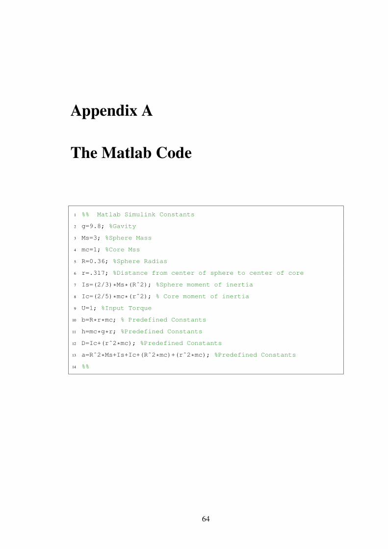
Appendix A
The Matlab Code
1 %% Matlab Simulink Constants
2 g=9.8; %Gavity
3 Ms=3; %Sphere Mass
4 mc=1; %Core Mss
5 R=0.36; %Sphere Radias
6 r=.317; %Distance from center of sphere to center of core
7 Is=(2/3)*Ms*(Rˆ2); %Sphere moment of inertia
8 Ic=(2/5)*mc*(rˆ2); % Core moment of inertia
9 U=1; %Input Torque
10 b=R*r*mc; % Predefined Constants
11 h=mc*g*r; %Predefined Constants
12 D=Ic+(rˆ2*mc); %Predefined Constants
13 a=Rˆ2*Ms+Is+Ic+(Rˆ2*mc)+(rˆ2*mc); %Predefined Constants
14 %%
64
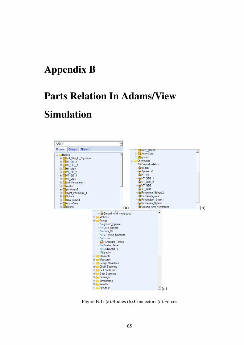
Appendix B
Parts Relation In Adams/View
Simulation
(a) (b)
(c)
Figure B.1: (a).Bodies (b).Connectors (c).Forces
65

(a) (b)
(c) (d)
Figure B.2: Normal Locomotion Definition: (a).Bodies (b).Connectors (c).Forces part
1 (d). Forces part 2
66
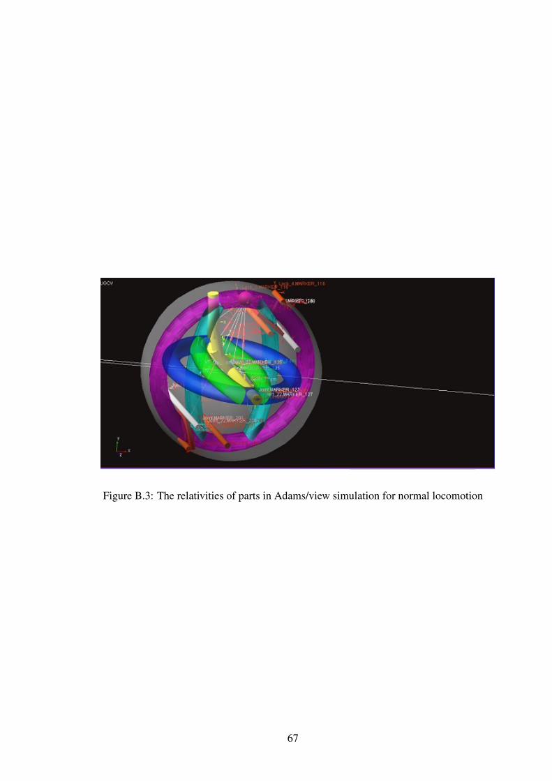
Figure B.3: The relativities of parts in Adams/view simulation for normal locomotion
67

(a) (b)
(c) (d)
Figure B.4: Circular Motion Definition: (a).Bodies (b).Connectors (c).Forces part 1 (d).
Forces part 2 68
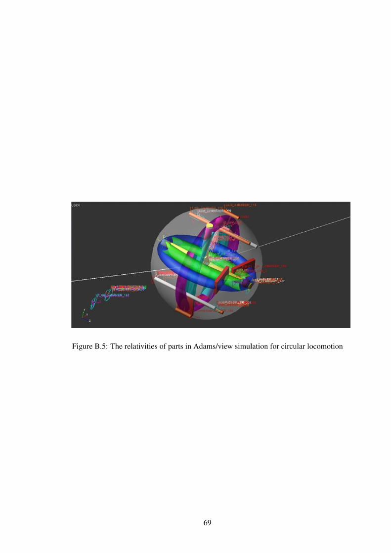
Figure B.5: The relativities of parts in Adams/view simulation for circular locomotion
69