Automatic Building of Structured ... - perso.liris.cnrs.fr · an automatic building of the model,...
11
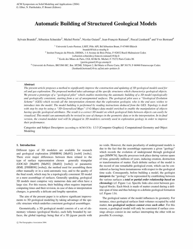
ACM Symposium on Solid Modeling and Applications (2004) G. Elber, N. Patrikalakis, P. Brunet (Editors) Automatic Building of Structured Geological Models Sylvain Brandel 1 , Sébastien Schneider 2 , Michel Perrin 3 , Nicolas Guiard 3 , Jean-François Rainaud 2 , Pascal Lienhardt 4 and Yves Bertrand 4 1 Université Louis-Pasteur, LSIIT, Pôle API, Bd Sébastien Brant, F-67400 Illkirch [email protected] 2 Institut Français du Pétrole, DISMA, 1-4 Avenue de Bois-Préau, F-92852 Rueil-Malmaison Cedex {sebastien.schneider,j-francois.rainaud}@ifp.fr 3 Ecole des Mines de Paris, CGI, 60 Bd St. Michel, F-75272 Paris Cedex 06 {perrin,guiard}@cge.ensmp.fr 4 Université de Poitiers, IRCOM-SIC, Bat. SP2MI, Téléport 2, Bd Marie et Pierre Curie, BP 30179, F-86960 Futuroscope Cedex {lienhardt,bertrand}@sic.sp2mi.univ-poitiers.fr Abstract The present article proposes a method to significantly improve the construction and updating of 3D geological models used for oil and gas exploration. The proposed method takes advantage of the specific structures which characterize geological objects. We present a prototype of a “geological pilot” which enables monitoring the automatic building of a 3D model topologically and geologically consistent, starting from a set of unsegmented surfaces. The geological pilot uses a “Geological Evolution Scheme” (GES) which records all the interpretation elements that the exploration geologist, who is the end user, wishes to introduce into the model. The model building is performed by reading instructions deduced from the GES. Topology is dealt with step by step by using a “3D Generalized Maps” (3-G-Maps) data model enriched to enable the manipulation of objects having specific geological attributes. The result is a correct 3D model on which geological links between objects can easily be visualized. This model can automatically be revised in case of changes in the geometric data or in the interpretation. In its final version, the created modular tool will be plugged in 3D modelers currently used in exploration geology in order to improve their performance. Categories and Subject Descriptors (according to ACM CCS): I.3.5 [Computer Graphics]: Computational Geometry and Object Modeling 1. Introduction Different types of 3D modelers are available for research and geological exploration [FHHR98] [Mal92] [webf] [webc]. There exist major differences between them related to the type of surface representation chosen generally triangular (GOCAD [Mal89] [Mal92] [Mal02] [webe]) or parametric (RML [FHHR98] [weba]), the method used for assembling them either manually or in a semi-automatic way, and to the quality of the final result, which may be a topologically consistent 3D model or a mere assemblage of surfaces. Generally speaking, geological 3D models must comprise very numerous data and often have a large size. For this reason, their building often requires important computing times and their revision, in case of data or interpretation changes, is generally a delicate and lengthy operation. The aim of the present paper is to achieve significant improve- ments to 3D geological modeling by taking advantage of the spe- cific structure which underlies consistent geological assemblages. Geometrically, a 3D geological model consists of a set of ele- mentary volumes (geological blocks), each fully bounded by sur- faces, the global topology being that of a 3D jigsaw puzzle with no voids. However, the main peculiarity of underground models is due to the fact that the assemblage represents a given “geology” which records the evolution of underground through geological ages [HMW76]. Specific processes took place during various spans of time, generally millions of years, inducing creation, destruction or transformation of matter. Each definite surface of the model is the record of one remarkable geological event, which can be con- sidered as having been instantaneous with respect to the geological time scale. Consequently, before building a model, the geologist interprets the “geology” to be represented by establishing between the various surfaces a total or partial order relationship based on chronology (cf. Figure 1.a). Specific links also exist between geo- logical blocks. Each block is made of matter created during a defi- nite span of time and thus belongs to a definite geological formation (cf. Figure 1.b). The geological nature of the model influences its geometry. For instance, since geological surfaces limit volumes occupied by solid matter, two geological surfaces cannot cross each other. For this reason, a geological model will only be consistent if surface cros- sings always consist in one surface interrupting the other with no possible X-crossings. c The Eurographics Association 2004.
Transcript of Automatic Building of Structured ... - perso.liris.cnrs.fr · an automatic building of the model,...
ACM Symposium on Solid Modeling and Applications (2004)G. Elber, N. Patrikalakis, P. Brunet (Editors)
Automatic Building of Structured Geological Models
Sylvain Brandel1, Sébastien Schneider2, Michel Perrin3, Nicolas Guiard3, Jean-François Rainaud2, Pascal Lienhardt4 and Yves Bertrand4
1 Université Louis-Pasteur, LSIIT, Pôle API, Bd Sébastien Brant, F-67400 [email protected]
2 Institut Français du Pétrole, DISMA, 1-4 Avenue de Bois-Préau, F-92852 Rueil-Malmaison Cedex{sebastien.schneider,j-francois.rainaud}@ifp.fr
3 Ecole des Mines de Paris, CGI, 60 Bd St. Michel, F-75272 Paris Cedex 06{perrin,guiard}@cge.ensmp.fr
4 Université de Poitiers, IRCOM-SIC, Bat. SP2MI, Téléport 2, Bd Marie et Pierre Curie, BP 30179, F-86960 Futuroscope Cedex{lienhardt,bertrand}@sic.sp2mi.univ-poitiers.fr
AbstractThe present article proposes a method to significantly improve the construction and updating of 3D geological models used foroil and gas exploration. The proposed method takes advantage of the specific structures which characterize geological objects.We present a prototype of a “geological pilot” which enables monitoring the automatic building of a 3D model topologicallyand geologically consistent, starting from a set of unsegmented surfaces. The geological pilot uses a “Geological EvolutionScheme” (GES) which records all the interpretation elements that the exploration geologist, who is the end user, wishes tointroduce into the model. The model building is performed by reading instructions deduced from the GES. Topology is dealtwith step by step by using a “3D Generalized Maps” (3-G-Maps) data model enriched to enable the manipulation of objectshaving specific geological attributes. The result is a correct 3D model on which geological links between objects can easily bevisualized. This model can automatically be revised in case of changes in the geometric data or in the interpretation. In its finalversion, the created modular tool will be plugged in 3D modelers currently used in exploration geology in order to improvetheir performance.
Categories and Subject Descriptors (according to ACM CCS): I.3.5 [Computer Graphics]: Computational Geometry and ObjectModeling
1. Introduction
Different types of 3D modelers are available for researchand geological exploration [FHHR98] [Mal92] [webf] [webc].There exist major differences between them related to thetype of surface representation chosen generally triangular(GOCAD [Mal89] [Mal92] [Mal02] [webe]) or parametric(RML [FHHR98] [weba]), the method used for assembling themeither manually or in a semi-automatic way, and to the quality ofthe final result, which may be a topologically consistent 3D modelor a mere assemblage of surfaces. Generally speaking, geological3D models must comprise very numerous data and often have alarge size. For this reason, their building often requires importantcomputing times and their revision, in case of data or interpretationchanges, is generally a delicate and lengthy operation.
The aim of the present paper is to achieve significant improve-ments to 3D geological modeling by taking advantage of the spe-cific structure which underlies consistent geological assemblages.
Geometrically, a 3D geological model consists of a set of ele-mentary volumes (geological blocks), each fully bounded by sur-faces, the global topology being that of a 3D jigsaw puzzle with
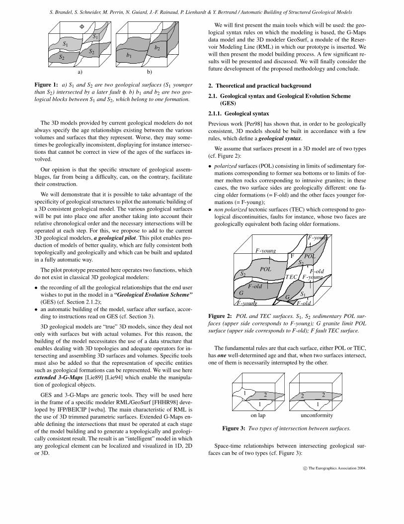
no voids. However, the main peculiarity of underground models isdue to the fact that the assemblage represents a given “geology”which records the evolution of underground through geologicalages [HMW76]. Specific processes took place during various spansof time, generally millions of years, inducing creation, destructionor transformation of matter. Each definite surface of the model isthe record of one remarkable geological event, which can be con-sidered as having been instantaneous with respect to the geologicaltime scale. Consequently, before building a model, the geologistinterprets the “geology” to be represented by establishing betweenthe various surfaces a total or partial order relationship based onchronology (cf. Figure 1.a). Specific links also exist between geo-logical blocks. Each block is made of matter created during a defi-nite span of time and thus belongs to a definite geological formation(cf. Figure 1.b).
The geological nature of the model influences its geometry. Forinstance, since geological surfaces limit volumes occupied by solidmatter, two geological surfaces cannot cross each other. For thisreason, a geological model will only be consistent if surface cros-sings always consist in one surface interrupting the other with nopossible X-crossings.
c© The Eurographics Association 2004.
S. Brandel, S. Schneider, M. Perrin, N. Guiard, J.-F. Rainaud, P. Lienhardt & Y. Bertrand / Automatic Building of Structured Geological Models
Φ
b2
a) b)
S1
S2b1
S2
S1
Figure 1: a) S1 and S2 are two geological surfaces (S1 youngerthan S2) intersected by a later fault φ. b) b1 and b2 are two geo-logical blocks between S1 and S2, which belong to one formation.
The 3D models provided by current geological modelers do notalways specify the age relationships existing between the variousvolumes and surfaces that they represent. Worse, they may some-times be geologically inconsistent, displaying for instance intersec-tions that cannot be correct in view of the ages of the surfaces in-volved.
Our opinion is that the specific structure of geological assem-blages, far from being a difficulty, can, on the contrary, facilitatetheir construction.
We will demonstrate that it is possible to take advantage of thespecificity of geological structures to pilot the automatic building ofa 3D consistent geological model. The various geological surfaceswill be put into place one after another taking into account theirrelative chronological order and the necessary intersections will beoperated at each step. For this, we propose to add to the current3D geological modelers, a geological pilot. This pilot enables pro-duction of models of better quality, which are fully consistent bothtopologically and geologically and which can be built and updatedin a fully automatic way.
The pilot prototype presented here operates two functions, whichdo not exist in classical 3D geological modelers:
• the recording of all the geological relationships that the end userwishes to put in the model in a “Geological Evolution Scheme”(GES) (cf. Section 2.1.2);
• an automatic building of the model, surface after surface, accor-ding to instructions read on GES (cf. Section 3).
3D geological models are “true” 3D models, since they deal notonly with surfaces but with actual volumes. For this reason, thebuilding of the model necessitates the use of a data structure thatenables dealing with 3D topologies and adequate operators for in-tersecting and assembling 3D surfaces and volumes. Specific toolsmust also be added so that the representation of specific entitiessuch as geological formations can be represented. We will use hereextended 3-G-Maps [Lie89] [Lie94] which enable the manipula-tion of geological objects.
GES and 3-G-Maps are generic tools. They will be used herein the frame of a specific modeler RML/GeoSurf [FHHR98] deve-loped by IFP/BEICIP [weba]. The main characteristic of RML isthe use of 3D trimmed parametric surfaces. Extended G-Maps en-able defining the intersections that must be operated at each stageof the model building and to generate a topologically and geologi-cally consistent result. The result is an “intelligent” model in whichany geological element can be localized and visualized in 1D, 2Dor 3D.
We will first present the main tools which will be used: the geo-logical syntax rules on which the modeling is based, the G-Mapsdata model and the 3D modeler GeoSurf, a module of the Reser-voir Modeling Line (RML) in which our prototype is inserted. Wewill then present the model building process. A few significant re-sults will be presented and discussed. We will finally consider thefuture development of the proposed methodology and conclude.
2. Theoretical and practical background
2.1. Geological syntax and Geological Evolution Scheme(GES)
2.1.1. Geological syntax
Previous work [Per98] has shown that, in order to be geologicallyconsistent, 3D models should be built in accordance with a fewrules, which define a geological syntax.
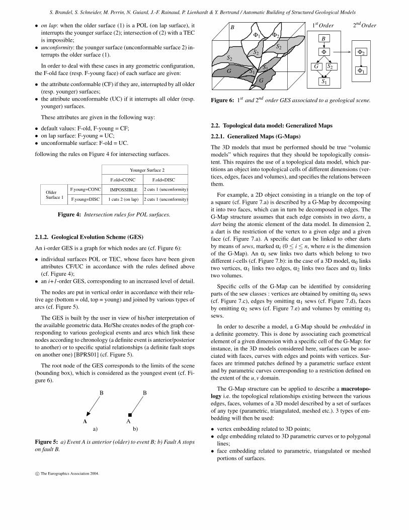
We assume that surfaces present in a 3D model are of two types(cf. Figure 2):
• polarized surfaces (POL) consisting in limits of sedimentary for-mations corresponding to former sea bottoms or to limits of for-mer molten rocks corresponding to intrusive granites; in thesecases, the two surface sides are geologically different: one fa-cing older formations (= F-old) and the other faces younger for-mations (= F-young);
• non polarized tectonic surfaces (TEC) which correspond to geo-logical discontinuities, faults for instance, whose two faces aregeologically equivalent both facing older formations.
GG
S2
F
S2POL
F-young
F-old
T EC
F-old
S1
F-youngF-old
F-young
POL
F-young
Figure 2: POL and TEC surfaces. S1, S2 sedimentary POL sur-faces (upper side corresponds to F-young); G granite limit POLsurface (upper side corresponds to F-old); F fault TEC surface.
The fundamental rules are that each surface, either POL or TEC,has one well-determined age and that, when two surfaces intersect,one of them is necessarily interrupted by the other.
unconformityon lap
21 2
1
2
1
Figure 3: Two types of intersection between surfaces.
Space-time relationships between intersecting geological sur-faces can be of two types (cf. Figure 3):
c© The Eurographics Association 2004.
S. Brandel, S. Schneider, M. Perrin, N. Guiard, J.-F. Rainaud, P. Lienhardt & Y. Bertrand / Automatic Building of Structured Geological Models
• on lap: when the older surface (1) is a POL (on lap surface), itinterrupts the younger surface (2); intersection of (2) with a TECis impossible;
• unconformity: the younger surface (unconformable surface 2) in-terrupts the older surface (1).
In order to deal with these cases in any geometric configuration,the F-old face (resp. F-young face) of each surface are given:
• the attribute conformable (CF) if they are, interrupted by all older(resp. younger) surfaces;
• the attribute unconformable (UC) if it interrupts all older (resp.younger) surfaces.
These attributes are given in the following way:
• default values: F-old, F-young = CF;• on lap surface: F-young = UC;• unconformable surface: F-old = UC.
following the rules on Figure 4 for intersecting surfaces.
F.young=CONC IMPOSSIBLE
F.old=CONC F.old=DISC
2 cuts 1 (unconformity)
2 cuts 1 (unconformity)Surface 1 F.young=DISC 1 cuts 2 (on lap)Older
Younger Surface 2
Figure 4: Intersection rules for POL surfaces.
2.1.2. Geological Evolution Scheme (GES)
An i-order GES is a graph for which nodes are (cf. Figure 6):
• individual surfaces POL or TEC, whose faces have been givenattributes CF/UC in accordance with the rules defined above(cf. Figure 4);
• an i+1-order GES, corresponding to an increased level of detail.
The nodes are put in vertical order in accordance with their rela-tive age (bottom = old, top = young) and joined by various types ofarcs (cf. Figure 5).
The GES is built by the user in view of his/her interpretation ofthe available geometric data. He/She creates nodes of the graph cor-responding to various geological events and arcs which link thesenodes according to chronology (a definite event is anterior/posteriorto another) or to specific spatial relationships (a definite fault stopson another one) [BPRS01] (cf. Figure 5).
The root node of the GES corresponds to the limits of the scene(bounding box), which is considered as the youngest event (cf. Fi-gure 6).
Aa) b)
B B
A
Figure 5: a) Event A is anterior (older) to event B; b) Fault A stopson fault B.
B
S2S2
S2
G
G
2ndOrder
B
Φ Φ2
1stOrder
Φ1 Φ2
S1S1 S2G
S1
Φ1
Figure 6: 1st and 2nd order GES associated to a geological scene.
2.2. Topological data model: Generalized Maps
2.2.1. Generalized Maps (G-Maps)
The 3D models that must be performed should be true “volumicmodels” which requires that they should be topologically consis-tent. This requires the use of a topological data model, which par-titions an object into topological cells of different dimensions (ver-tices, edges, faces and volumes), and specifies the relations betweenthem.
For example, a 2D object consisting in a triangle on the top ofa square (cf. Figure 7.a) is described by a G-Map by decomposingit into two faces, which can in turn be decomposed in edges. TheG-Map structure assumes that each edge consists in two darts, adart being the atomic element of the data model. In dimension 2,a dart is the restriction of the vertex to a given edge and a givenface (cf. Figure 7.a). A specific dart can be linked to other dartsby means of sews, marked αi (0 ≤ i ≤ n, where n is the dimensionof the G-Map). An αi sew links two darts which belong to twodifferent i-cells (cf. Figure 7.b): in the case of a 3D model, α0 linkstwo vertices, α1 links two edges, α2 links two faces and α3 linkstwo volumes.
Specific cells of the G-Map can be identified by consideringparts of the sew classes : vertices are obtained by omitting α0 sews(cf. Figure 7.c), edges by omitting α1 sews (cf. Figure 7.d), facesby omitting α2 sews (cf. Figure 7.e) and volumes by omitting α3sews.
In order to describe a model, a G-Map should be embedded ina definite geometry. This is done by associating each geometricalelement of a given dimension with a specific cell of the G-Map: forinstance, in the 3D models considered here, surfaces can be asso-ciated with faces, curves with edges and points with vertices. Sur-faces are trimmed patches defined by a parametric surface extentand by parametric curves corresponding to a restriction defined onthe extent of the u,v domain.
The G-Map structure can be applied to describe a macrotopo-logy i.e. the topological relationships existing between the variousedges, faces, volumes of a 3D model described by a set of surfacesof any type (parametric, triangulated, meshed etc.). 3 types of em-bedding will then be used:
• vertex embedding related to 3D points;• edge embedding related to 3D parametric curves or to polygonal
lines;• face embedding related to parametric, triangulated or meshed
portions of surfaces.
c© The Eurographics Association 2004.
S. Brandel, S. Schneider, M. Perrin, N. Guiard, J.-F. Rainaud, P. Lienhardt & Y. Bertrand / Automatic Building of Structured Geological Models
dart
Vertex Orbit Edge Orbit Face Orbit
α1 relationsα2 relations
α0 relations
b)a)
d)c) e)
Figure 7: 2-G-Maps description: a) darts corresponding to geo-metric object; b) relations between darts; c) vertex orbit; d) edgeorbit; e) face orbit.
In the case of a model consisting of triangulated or meshed sur-faces, the G-Map structure can also be applied to describe the re-lationships between the various elementary edges and triangular orpolyhedral surfaces (microtopology) (cf. Figure 8).
a) b)
Figure 8: a) Macrotopological and b) microtopological descrip-tion of a parametric surface divided in two patches.
2.2.2. Extension for describing geological relationships
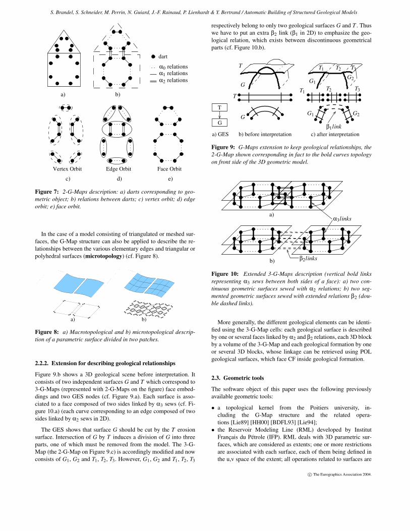
Figure 9.b shows a 3D geological scene before interpretation. Itconsists of two independent surfaces G and T which correspond to3-G-Maps (represented with 2-G-Maps on the figure) face embed-dings and two GES nodes (cf. Figure 9.a). Each surface is asso-ciated to a face composed of two sides linked by α3 sews (cf. Fi-gure 10.a) (each curve corresponding to an edge composed of twosides linked by α2 sews in 2D).
The GES shows that surface G should be cut by the T erosionsurface. Intersection of G by T induces a division of G into threeparts, one of which must be removed from the model. The 3-G-Map (the 2-G-Map on Figure 9.c) is accordingly modified and nowconsists of G1, G2 and T1, T2, T3. However, G1, G2 and T1, T2, T3
respectively belong to only two geological surfaces G and T . Thuswe have to put an extra β2 link (β1 in 2D) to emphasize the geo-logical relation, which exists between discontinuous geometricalparts (cf. Figure 10.b).
c) after interpretationb) before interpretation
T
G
a) GES
T
G
G
T3
T1T2 T3
G1
G1
T
β1link
T1
G2
G2
T2
Figure 9: G-Maps extension to keep geological relationships, the2-G-Map shown corresponding in fact to the bold curves topologyon front side of the 3D geometric model.
a)α3links
β2linksb)
Figure 10: Extended 3-G-Maps description (vertical bold linksrepresenting α3 sews between both sides of a face): a) two con-tinuous geometric surfaces sewed with α2 relations; b) two seg-mented geometric surfaces sewed with extended relations β2 (dou-ble dashed links).
More generally, the different geological elements can be identi-fied using the 3-G-Map cells: each geological surface is describedby one or several faces linked by α2 and β2 relations, each 3D blockby a volume of the 3-G-Map and each geological formation by oneor several 3D blocks, whose linkage can be retrieved using POLgeological surfaces, which face CF inside geological formation.
2.3. Geometric tools
The software object of this paper uses the following previouslyavailable geometric tools:
• a topological kernel from the Poitiers university, in-cluding the G-Map structure and the related opera-tions [Lie89] [HH00] [BDFL93] [Lie94];
• the Reservoir Modeling Line (RML) developed by InstitutFrançais du Pétrole (IFP). RML deals with 3D parametric sur-faces, which are considered as extents; one or more restrictionsare associated with each surface, each of them being defined inthe u,v space of the extent; all operations related to surfaces are
c© The Eurographics Association 2004.
S. Brandel, S. Schneider, M. Perrin, N. Guiard, J.-F. Rainaud, P. Lienhardt & Y. Bertrand / Automatic Building of Structured Geological Models
operated on the restrictions and thus correspond to 2D opera-tions.
RML uses a few features of CAS.CADE, a huge CAD librarydeveloped by MATRA-DATAVISION in 1993 [webb] to manageall geometrical operations involving parametric surfaces. This en-ables consideration of intensively deformed surfaces that can be inoverlapping position, a common case in geology. Its main advan-tages are robustness and stability. Moreover, parametric surfacesenable dealing with incertitudes in a very flexible way. However,computing time can be rather long when high precision is required.CAS.CADE is now available in open source [webb].
G-Maps and CAS.CADE libraries are used together, CAS.CADE objects corresponding to the embedding of G-Maps objects.
3. Model building
3.1. Overall model building methodology
The overall methodology proposed here involves the four main fol-lowing operations:
1. data input and GES building;2. determination of the intersections to be performed;3. fault preprocessing;4. model building (involving at each stage surface intersection and
removal of all undesired parts).
3.1.1. Data input and GES building
Initial surfaces are assumed to be continuous, unstructured and geo-metrically independent from one another, possible intersections be-tween them being ignored.
The GES must be built by the user before the building of themodel itself. For this, he/she must define the relative age order ofthe various geological surfaces and define the properties of eachof them: POL or TEC and in the case of a POL surface, CF orUC. He/She also specifies the links between the various geologicalsurfaces and the various files describing their geometries (cf. Fi-gure 11).
For the moment, the above operations are executed manually.However, an independent user interface is presently being built andwill allow to define the links and properties of the various geo-logical surfaces, and to insert them in a GES that will be built au-tomatically [BHB03].
F B
F
H
H
B
Figure 11: Data input: two unsegmented geological surfaces Fand H and the corresponding GES. Each arrow goes from theyounger surface to the older one.
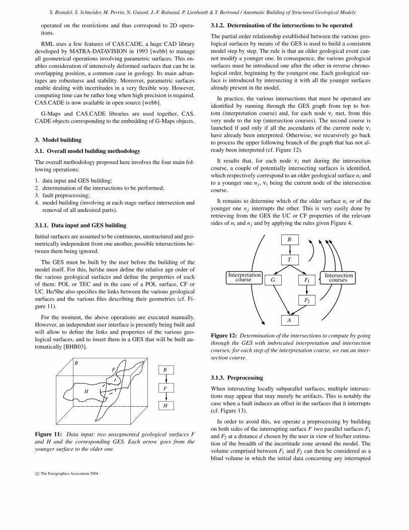
3.1.2. Determination of the intersections to be operated
The partial order relationship established between the various geo-logical surfaces by means of the GES is used to build a consistentmodel step by step. The rule is that an older geological event can-not modify a younger one. In consequence, the various geologicalsurfaces must be introduced one after the other in reverse chrono-logical order, beginning by the youngest one. Each geological sur-face is introduced by intersecting it with all the younger surfacesalready present in the model.
In practice, the various intersections that must be operated areidentified by running through the GES graph from top to bot-tom (interpretation course) and, for each node νi met, from thisvery node to the top (intersection courses). The second course islaunched if and only if all the ascendants of the current node νihave already been interpreted. Otherwise, we recursively go backto process the upper following branch of the graph that has not al-ready been interpreted (cf. Figure 12).
It results that, for each node νi met during the intersectioncourse, a couple of potentially intersecting surfaces is identified,which respectively correspond to an older geological surface ni andto a younger one n j , νi being the current node of the intersectioncourse.
It remains to determine which of the older surface ni or of theyounger one n j interrupts the other. This is very easily done byretrieving from the GES the UC or CF properties of the relevantsides of ni and n j and by applying the rules given Figure 4.
B
T
F1G
F2
A
Interpretationcourse
Intersectioncourses
Figure 12: Determination of the intersections to compute by goingthrough the GES with imbricated interpretation and intersectioncourses; for each step of the interpretation course, we run an inter-section course.
3.1.3. Preprocessing
When intersecting locally subparallel surfaces, multiple intersec-tions may appear that may merely be artifacts. This is notably thecase when a fault induces an offset in the surfaces that it interrupts(cf. Figure 13).
In order to avoid this, we operate a preprocessing by buildingon both sides of the interrupting surface F two parallel surfaces F1and F2 at a distance d chosen by the user in view of his/her estima-tion of the breadth of the incertitude zone around the model. Thevolume comprised between F1 and F2 can then be considered as ablind volume in which the initial data concerning any interrupted
c© The Eurographics Association 2004.
S. Brandel, S. Schneider, M. Perrin, N. Guiard, J.-F. Rainaud, P. Lienhardt & Y. Bertrand / Automatic Building of Structured Geological Models
surface H can be considered as no longer valid. In practice, thismay sometimes induce the splitting of H into different parts thatmust be sewn by β2 topological relations in order to express thatthey are parts of one geological surface (cf. Figure 13).
H
H
F
F1
F2
Figure 13: The preprocessing stage.
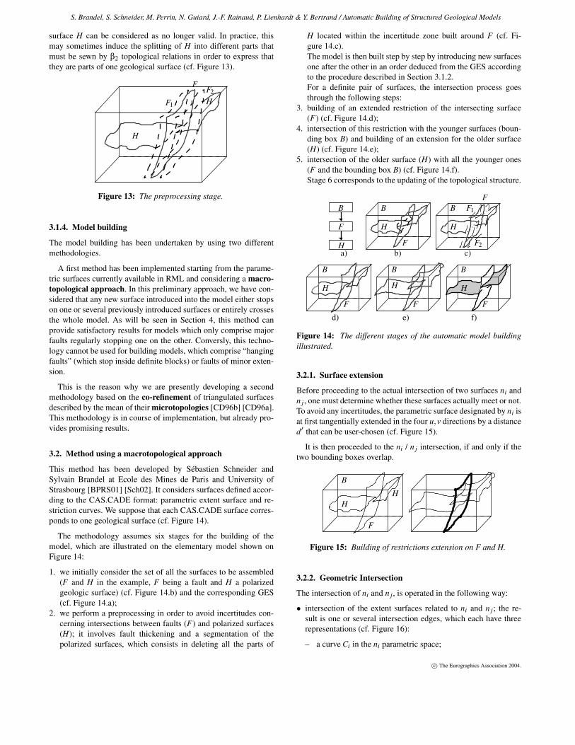
3.1.4. Model building
The model building has been undertaken by using two differentmethodologies.
A first method has been implemented starting from the parame-tric surfaces currently available in RML and considering a macro-topological approach. In this preliminary approach, we have con-sidered that any new surface introduced into the model either stopson one or several previously introduced surfaces or entirely crossesthe whole model. As will be seen in Section 4, this method canprovide satisfactory results for models which only comprise majorfaults regularly stopping one on the other. Conversly, this techno-logy cannot be used for building models, which comprise “hangingfaults” (which stop inside definite blocks) or faults of minor exten-sion.
This is the reason why we are presently developing a secondmethodology based on the co-refinement of triangulated surfacesdescribed by the mean of their microtopologies [CD96b] [CD96a].This methodology is in course of implementation, but already pro-vides promising results.
3.2. Method using a macrotopological approach
This method has been developed by Sébastien Schneider andSylvain Brandel at Ecole des Mines de Paris and University ofStrasbourg [BPRS01] [Sch02]. It considers surfaces defined accor-ding to the CAS.CADE format: parametric extent surface and re-striction curves. We suppose that each CAS.CADE surface corres-ponds to one geological surface (cf. Figure 14).
The methodology assumes six stages for the building of themodel, which are illustrated on the elementary model shown onFigure 14:
1. we initially consider the set of all the surfaces to be assembled(F and H in the example, F being a fault and H a polarizedgeologic surface) (cf. Figure 14.b) and the corresponding GES(cf. Figure 14.a);
2. we perform a preprocessing in order to avoid incertitudes con-cerning intersections between faults (F) and polarized surfaces(H); it involves fault thickening and a segmentation of thepolarized surfaces, which consists in deleting all the parts of
H located within the incertitude zone built around F (cf. Fi-gure 14.c).The model is then built step by step by introducing new surfacesone after the other in an order deduced from the GES accordingto the procedure described in Section 3.1.2.For a definite pair of surfaces, the intersection process goesthrough the following steps:
3. building of an extended restriction of the intersecting surface(F) (cf. Figure 14.d);
4. intersection of this restriction with the younger surfaces (boun-ding box B) and building of an extension for the older surface(H) (cf. Figure 14.e);
5. intersection of the older surface (H) with all the younger ones(F and the bounding box B) (cf. Figure 14.f).Stage 6 corresponds to the updating of the topological structure.
F
B B
BBB
H
F
H
H
B
F
H
F1
F2
H
F F F
H
b) c)a)
d) e) f)
Figure 14: The different stages of the automatic model buildingillustrated.
3.2.1. Surface extension
Before proceeding to the actual intersection of two surfaces ni andn j , one must determine whether these surfaces actually meet or not.To avoid any incertitudes, the parametric surface designated by ni isat first tangentially extended in the four u,v directions by a distanced′ that can be user-chosen (cf. Figure 15).
It is then proceeded to the ni / n j intersection, if and only if thetwo bounding boxes overlap.
H
B
H
F
Figure 15: Building of restrictions extension on F and H.
3.2.2. Geometric Intersection
The intersection of ni and n j , is operated in the following way:
• intersection of the extent surfaces related to ni and n j; the re-sult is one or several intersection edges, which each have threerepresentations (cf. Figure 16):
– a curve Ci in the ni parametric space;
c© The Eurographics Association 2004.
S. Brandel, S. Schneider, M. Perrin, N. Guiard, J.-F. Rainaud, P. Lienhardt & Y. Bertrand / Automatic Building of Structured Geological Models
– a curve C j in the n j parametric space;– a 3D parametric curve C3D.
• in each of the ni and n j parametric spaces, intersection of Ci (respC j) with the ni (resp n j) restriction curves;
• removal of one portion of the surface ni or n j which is interruptedby the other. Assuming that the interrupted surface is ni, we keepthe portion of ni containing original data.
Ci
nirestriction
ni
n jn jrestriction
C jC3D
Figure 16: Geometric intersections between surfaces and then be-tween restrictions.
3.2.3. Updating of the G-Map structure
After having performed all the intersections of the geological sur-faces corresponding to a node νi with all the younger surfaces n j ,it is necessary to update the G-Map structure in order to insert theni surface itself and all the divisions that ni has induced on the n jsurfaces in the model. The updated G-Map structure is obtainedby refining the new topological faces created by the intersectionand by updating their embeddings. This is performed with specificalgorithms developed in [Sch02].
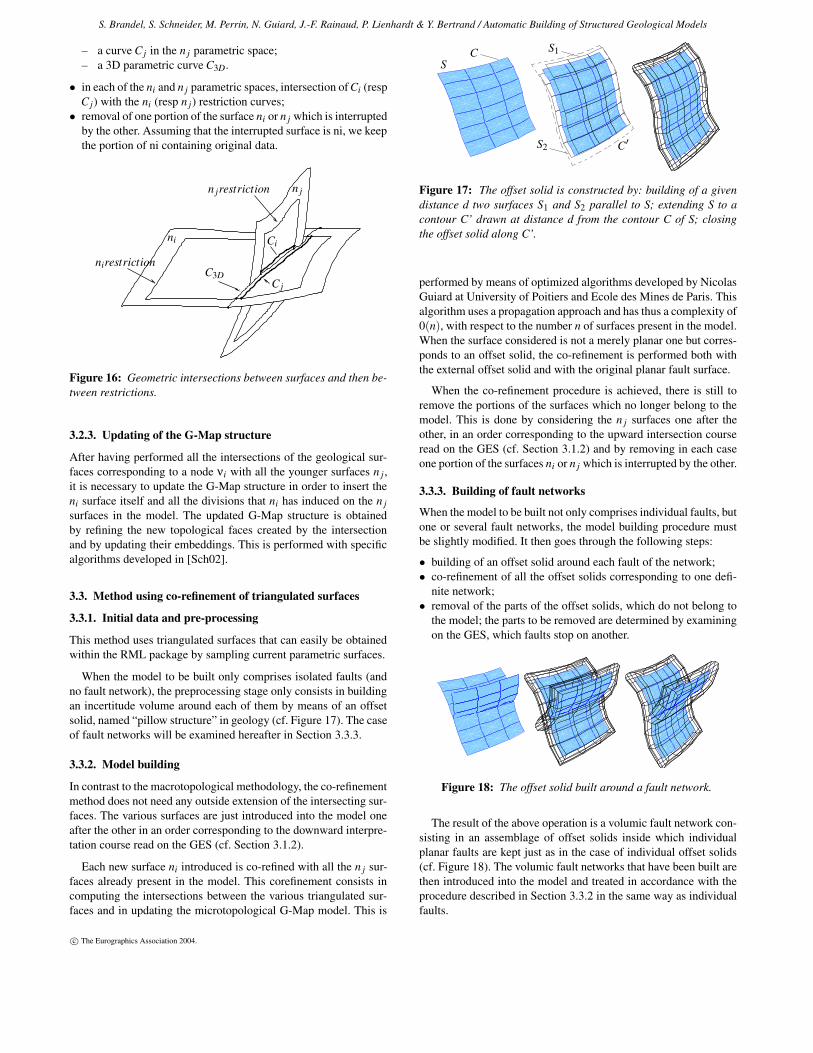
3.3. Method using co-refinement of triangulated surfaces
3.3.1. Initial data and pre-processing
This method uses triangulated surfaces that can easily be obtainedwithin the RML package by sampling current parametric surfaces.
When the model to be built only comprises isolated faults (andno fault network), the preprocessing stage only consists in buildingan incertitude volume around each of them by means of an offsetsolid, named “pillow structure” in geology (cf. Figure 17). The caseof fault networks will be examined hereafter in Section 3.3.3.
3.3.2. Model building
In contrast to the macrotopological methodology, the co-refinementmethod does not need any outside extension of the intersecting sur-faces. The various surfaces are just introduced into the model oneafter the other in an order corresponding to the downward interpre-tation course read on the GES (cf. Section 3.1.2).
Each new surface ni introduced is co-refined with all the n j sur-faces already present in the model. This corefinement consists incomputing the intersections between the various triangulated sur-faces and in updating the microtopological G-Map model. This is
SC S1
S2 C′
Figure 17: The offset solid is constructed by: building of a givendistance d two surfaces S1 and S2 parallel to S; extending S to acontour C’ drawn at distance d from the contour C of S; closingthe offset solid along C’.
performed by means of optimized algorithms developed by NicolasGuiard at University of Poitiers and Ecole des Mines de Paris. Thisalgorithm uses a propagation approach and has thus a complexity of0(n), with respect to the number n of surfaces present in the model.When the surface considered is not a merely planar one but corres-ponds to an offset solid, the co-refinement is performed both withthe external offset solid and with the original planar fault surface.
When the co-refinement procedure is achieved, there is still toremove the portions of the surfaces which no longer belong to themodel. This is done by considering the n j surfaces one after theother, in an order corresponding to the upward intersection courseread on the GES (cf. Section 3.1.2) and by removing in each caseone portion of the surfaces ni or n j which is interrupted by the other.
3.3.3. Building of fault networks
When the model to be built not only comprises individual faults, butone or several fault networks, the model building procedure mustbe slightly modified. It then goes through the following steps:
• building of an offset solid around each fault of the network;• co-refinement of all the offset solids corresponding to one defi-
nite network;• removal of the parts of the offset solids, which do not belong to
the model; the parts to be removed are determined by examiningon the GES, which faults stop on another.
Figure 18: The offset solid built around a fault network.
The result of the above operation is a volumic fault network con-sisting in an assemblage of offset solids inside which individualplanar faults are kept just as in the case of individual offset solids(cf. Figure 18). The volumic fault networks that have been built arethen introduced into the model and treated in accordance with theprocedure described in Section 3.3.2 in the same way as individualfaults.
c© The Eurographics Association 2004.
S. Brandel, S. Schneider, M. Perrin, N. Guiard, J.-F. Rainaud, P. Lienhardt & Y. Bertrand / Automatic Building of Structured Geological Models
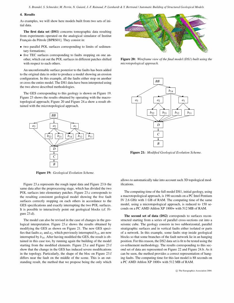
4. Results
As examples, we will show here models built from two sets of ini-tial data.
The first data set (DS1) concerns tomographic data resultingfrom experiments operated on the analogical simulator of InstitutFrançais du Pétrole [BPRS01]. They consist in:
• two parallel POL surfaces corresponding to limits of sedimen-tary formations;
• five TEC surfaces corresponding to faults stopping on one an-other, which cut out the POL surfaces in different patches shiftedwith respect to each others.
An unconformable surface posterior to the faults has been addedto the original data in order to produce a model showing an erosionconfiguration. In this example, all the faults either stop on anotheror cross the entire model. The DS1 data have been interpreted usingthe two above described methodologies.
The GES corresponding to this geology is shown on Figure 19.Figure 23 shows the results obtained by operating with the macro-topological approach; Figure 20 and Figure 24.a show a result ob-tained with the microtopological approach.
a3 a2
b12
a1
D
C
B
BB
b22 b14 b11b21
Figure 19: Geological Evolution Scheme.
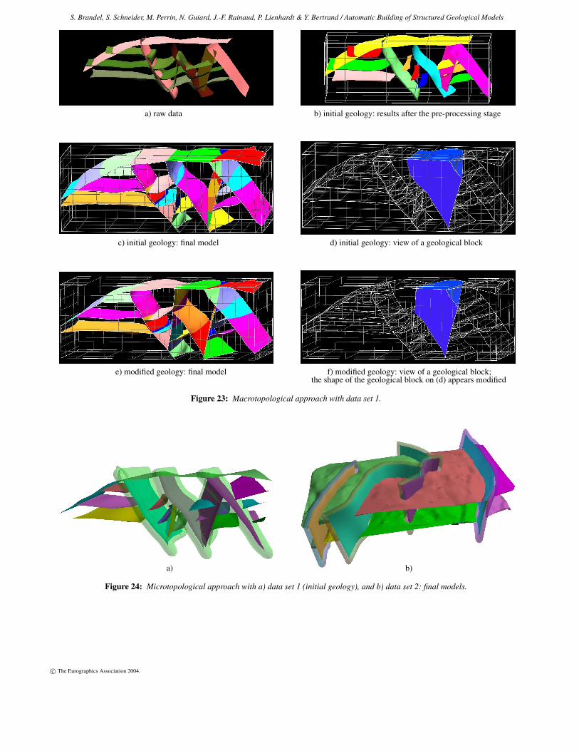
Figure 23.a represents the rough input data and Figure 23.b thesame data after the preprocessing stage, which has divided the twoPOL surfaces into elementary patches. Figure 23.c corresponds tothe resulting consistent geological model showing the five faultsurfaces correctly stopping on each others in accordance to theGES specifications and exactly interrupting the two POL surfaces.It is possible to interactively point out geological blocks (cf. Fi-gure 23.d).
The model can also be revised in the case of changes in the geo-logical interpretation. Figure 23.e shows the results obtained bymodifying the GES as shown on Figure 21. The new GES speci-fies that faults a1 and a2, which previously interrupted b14, are nowinterrupted by b14. After having modified the GES, the result is ob-tained in this case too, by running again the building of the modelstarting from the modified elements. Figure 23.e and Figure 23.fshow that the change in the GES has induced severe modificationsin the topology. Particularly, the shape of the bloc on Figure 23.fdiffers near the fault on the middle of the scene. This is an out-standing result, the method that we propose being the only which
Figure 20: Wireframe view of the final model (DS1) built using themicrotopological approach.
B
C
D
a3
BB
b14
a2
b22 b21 b12 b11
a1
Figure 21: Modified Geological Evolution Scheme.
allows to automatically take into account such 3D topological mod-ifications.
The computing time of the full model DS1, initial geology, usinga macrotopological approach, is 190 seconds on a PC Intel PentiumIV 2.6 GHz with 1 GB of RAM. The computing time of the samemodel, using a microtopological approach, is reduced to 150 se-conds on a PC AMD Athlon XP 1800+ with 512 MB of RAM.
The second set of data (DS2) corresponds to surfaces recon-structed starting from a series of parallel cross-sections cut into aseismic cube. The geology consists in two subhorizontal, parallelstratigraphic surfaces and in vertical faults either isolated or partsof a network. In this example, some faults stop inside geologicalblocks so that some branches of the fault network lie in an hangingposition. For this reason, the DS2 data set is fit to be tested using theco-refinement methodology. The results corresponding to this sec-ond set of data are represented on Figure 22 and Figure 24.b. As itcan be seen, the method provides a correct representation of hang-ing faults. The computing time for this last model is 88 seconds ona PC AMD Athlon XP 1800+ with 512 MB of RAM.
c© The Eurographics Association 2004.
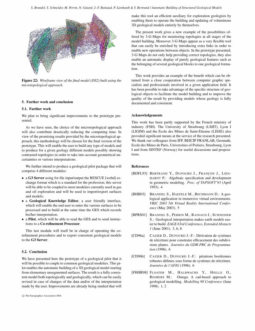
S. Brandel, S. Schneider, M. Perrin, N. Guiard, J.-F. Rainaud, P. Lienhardt & Y. Bertrand / Automatic Building of Structured Geological Models
Figure 22: Wireframe view of the final model (DS2) built using themicrotopological approach.
5. Further work and conclusion
5.1. Further work
We plan to bring significant improvements to the prototype pre-sented.
As we have seen, the choice of the microtopological approachwill also contribute drastically reducing the computing time. Inview of the promising results provided by the microtopological ap-proach, this methodology will be chosen for the final version of theprototype. This will enable the user to build any type of models andto produce for a given geology different models possibly showingcontrasted topologies in order to take into account geometrical un-certainties or various interpretations.
We further intend to produce a geological pilot package that willcomprise 4 different modules:
• a G3 Server using for file input/output the RESCUE [webd] ex-change format which is a standard for the profession; this serverwill be able to be coupled to most modelers currently used in gasand oil exploration and will be used to import/export surfacesand models;
• a Geological Knowledge Editor, a user friendly interface,which will enable the end user to enter the various surfaces to beprocessed and to build at the same time the GES which recordshis/her interpretation;
• a Pilot, which will be able to read the GES and to send instruc-tions to a Co-refinement Processor.
This last module will itself be in charge of operating the co-refinement procedures and to export consistent geological modelsto the G3 Server.
5.2. Conclusion
We have presented here the prototype of a geological pilot that itwill be possible to couple to common geological modelers. This pi-lot enables the automatic building of a 3D geological model startingfrom elementary unsegmented surfaces. The result is a fully consis-tent model both topologically and geologically, which can be easilyrevised in case of changes of the data and/or of the interpretationmade by the user. Improvements are already being studied that will
make this tool an efficient auxiliary for exploration geologists byenabling them to operate the building and updating of voluminous3D geological models entirely by themselves.
The present work gives a new example of the possibilities of-fered by 3-G-Maps for monitoring topologies at all stages of themodel building. Moreover 3-G-Maps appear as a very flexible toolthat can easily be enriched by introducing extra links in order toenable new operations between objects. In the prototype presented,3-G-Maps do not only help providing correct topologies, they alsoenable an automatic display of purely geological features such asthe belonging of several geological blocks to one geological forma-tion.
This work provides an example of the benefit which can be ob-tained from a close cooperation between computer graphic spe-cialists and professionals involved in a given application field. Ithas been possible to take advantage of the specific structure of geo-logical objects to facilitate the model building and to improve thequality of the result by providing models whose geology is fullydocumented and consistent.
Acknowledgements
This work has been partly supported by the French ministry ofindustry (FSH). The University of Strasbourg (LSIIT), Lyon I(LIGIM) and the Ecole des Mines de Saint-Etienne (LISSE) alsoprovided significant means at the service of the research presented.We thank our colleagues from IFP, BEICIP FRANLAB, Geomath,Ecole des Mines de Paris, Universities of Poitiers, Strasbourg, LyonI and from SINTEF (Norway) for useful discussions and proposi-tions.
References
[BDFL93] BERTRAND Y., DUFOURD J., FRANÇON J., LIEN-HARDT P.: Algebraic specification and developmentin geometric modeling. Proc. of TAPSOFT’93 (April1993). 4
[BHB03] BRANDEL S., HAEFELE M., BECHMANN D.: A geo-logical application in immersive virtual environments.VRIC 2003 5th Virtual Reality International Confer-ence (May 2003). 5
[BPRS01] BRANDEL S., PERRIN M., RAINAUD J., SCHNEIDER
S.: Geological interpretation makes earth models eas-ier to build. EAGE 63rd Conference, Extended Abstacts1 (June 2001). 3, 6, 8
[CD96a] CAZIER D., DUFOURD J.-F.: Dérivation de systèmesde réécriture pour construire efficacement des subdivi-sions planes. Journées du GDR-PRC de Programma-tion (1996). 6
[CD96b] CAZIER D., DUFOURD J.-F.: pérations booléennesrobustes définies sous forme de systèmes de réécriture.Journées de l’AFIG (1996). 6
[FHHR98] FLOATER M., HALBWACHS Y., HJELLE O.,REIMERS M.: Omega: A cad-based approach togeological modelling. Modelling 98 Conference (June1998). 1, 2
c© The Eurographics Association 2004.
S. Brandel, S. Schneider, M. Perrin, N. Guiard, J.-F. Rainaud, P. Lienhardt & Y. Bertrand / Automatic Building of Structured Geological Models
[HH00] HALBWACHS Y., HJELLE O.: Generalized maps ingeological modeling: Object-oriented design of topo-logical kernels. Advances in Software Tools for Scien-tific Computing 10, 1 (2000), 339–356. 4
[HMW76] HOBBS B., MEANS W., WILLIAMS P.: An Outline ofStructural Geology. Wiley and sons, 1976. 1
[Lie89] LIENHARDT P.: Subdivision of n-dimensional spacesand n-dimensional generalized maps. In 5th ACM Sym-posium on Computational Geometry (1989), 228–236.2, 4
[Lie94] LIENHARDT P.: N-dimensional generalized combina-torial maps and cellular quasi-manifolds. Journal ofComputational Geometry and Applications 4, 3 (1994),275–324. 2, 4
[Mal89] MALLET J.-L.: Discrete smooth interpolation in geo-metric modeling. ACM-Transactions on Graphics 8, 2(1989), 121–144. 1
[Mal92] MALLET J.-L.: Gocad: a computer-aided design pro-gram for geological applications. Three-DimensionalModeling with Geoscientific Information Systems 354(1992), 123–142. 1
[Mal02] MALLET J.-L.: Geomodeling. Oxford UniversityPress, 2002. 1
[Per98] PERRIN M.: Geological consistency: an opportunityfor safe surface assembly and quick model exploration.3D Modeling of Natural Objects, A Challenge for the2000’s 3, 4-5 (June 1998). 2
[Sch02] SCHNEIDER S.: Pilotage automatique de la construc-tion de modèles géologiques surfaciques. PhD thesis,Université Jean Monnet and Ecole des Mines de Saint-Etienne, 2002. 6, 7
[weba] WEBSITE: The beicip web site. World Wide Web doc-ument at http://www.beicip.com/. 1, 2
[webb] WEBSITE: The cas.cade web site. World Wide Webdocument at http://www.opencascade.org/. 5
[webc] WEBSITE: The earthvision web site. World Wide Webdocument at http://www.dgi.com/. 1
[webd] WEBSITE: The file exchange format rescue. WorldWide Web document at http://www.posc.org/rescue/. 9
[webe] WEBSITE: The gocad web site. World Wide Web doc-ument at http://www.gocad.com/. 1
[webf] WEBSITE: The landmark web site. World Wide Webdocument at http://www.lgc.com/. 1
c© The Eurographics Association 2004.
S. Brandel, S. Schneider, M. Perrin, N. Guiard, J.-F. Rainaud, P. Lienhardt & Y. Bertrand / Automatic Building of Structured Geological Models
the shape of the geological block on (d) appears modified
c) initial geology: final model d) initial geology: view of a geological block
b) initial geology: results after the pre-processing stagea) raw data
e) modified geology: final model f) modified geology: view of a geological block;
Figure 23: Macrotopological approach with data set 1.
a) b)
Figure 24: Microtopological approach with a) data set 1 (initial geology), and b) data set 2: final models.
c© The Eurographics Association 2004.