Automatic Adjustment of Phase Shifting Transformers...
15
149 Automatic Adjustment of Phase Shifting Transformers – the Ability to Control the Active Power Flow in International Exchange Lines Authors Ksawery Opala Tomasz Ogryczak Keywords phase shifting transformers, control system, active power flow control Abstract The authors presented the characteristics of Mikułowa substation in terms of its location and grid connections, brief functional description of its automatic controls, and the results of tests of the automatic control of four phase shifting transformers installed in Mikułowa – Hagenwerder international exchange lines. The tests were carried out as part of the phase shifting transformers’ commissioning at Mikułowa substation in 2016. These results allow one to verify the actual range of control of active power flow between the power system of Poland and Germany, and the control’s effect on the power flow in the NPS. This is the first such installation on a cross-border interconnection in Poland. So far the active power flow in the National Power System (NPS) has never been altered with the use of phase shifting transformers. DOI: 10.12736/issn.2300-3022.2017212 Received: 15.02.2017 Accepted: 27.03.2017 Available online: 30.06.2017 1. Introduction The origin of this article was the practical experience related to the installation of four phase shifting transformers, rated at 1,200 MVA each, at the Mikułowa substation. Phase shifting transformers with such rated power that have not been used in the NPS before. Yet they are operated in foreign power systems, e.g. in Germany – at Diele substation. The phase shifting trans- formers (PSTs) have been installed in two 400 kV Mikułowa – Hagenwerder international exchange lines to control the active power flow. The PSTs (Fig. 1) are practically symmetrical (sides: Source – S and Load – L) and each of them consists of two sepa- rate transformers: series and exciter. Both windings of the exciter transformer are star-connected. Its primary winding is powered from the grid and the secondary winding interoperates with the on-load tap-changer. The series transformer’s secondary winding, which generates the booster voltage, is connected in series with the line, in which the voltage phase shift is controlled. The full line current flows also through the winding. The series transformer’s primary winding is, however, delta-connected (which provides a voltage shift of π/2) and is powered from the exciter transformer’s control winding [1]. The control of active power flow through the phase shifting transformers consists in changing the flow without changing the aggregate power output to the grid. The known dependency is used here, which determines the active power flow in a single inductive branch. It has the following form [2]: (1) where: P – active power outgoing from the branch, U i , U j – at beginning and end of the branch, δ – load angle (difference of node voltage arguments at the beginning and end of the branch, δ = δ i – δ j ). The active power flow control with phase shifting transformers consists in changing the load angle by changing the tap posi- tion in the exciter transformer’s secondary winding. The phase shifting transformers at Mikułowa substation have 65 control steps (±32 taps), with which the value and direction of the active power flow in MIK-HAG (Mikułowa-Hagenwerder) line can be changed. They are provided with two interoperable Reinhausen tap changers. The first on-load tap changer (OLTC) adjusts the tap positions in the range of 0... 32 and is located at the exciter K. Opala, T. Ogryczak | Acta Energetica 2/31 (2017) | 149–157
Transcript of Automatic Adjustment of Phase Shifting Transformers...

149
Automatic Adjustment of Phase Shifting Transformers – the Ability to Control the Active Power Flow in International Exchange Lines
AuthorsKsawery OpalaTomasz Ogryczak
Keywordsphase shifting transformers, control system, active power flow control
AbstractThe authors presented the characteristics of Mikułowa substation in terms of its location and grid connections, brief functional description of its automatic controls, and the results of tests of the automatic control of four phase shifting transformers installed in Mikułowa – Hagenwerder international exchange lines. The tests were carried out as part of the phase shifting transformers’ commissioning at Mikułowa substation in 2016. These results allow one to verify the actual range of control of active power flow between the power system of Poland and Germany, and the control’s effect on the power flow in the NPS. This is the first such installation on a cross-border interconnection in Poland. So far the active power flow in the National Power System (NPS) has never been altered with the use of phase shifting transformers.
DOI: 10.12736/issn.2300-3022.2017212
Received: 15.02.2017Accepted: 27.03.2017Available online: 30.06.2017
1. IntroductionThe origin of this article was the practical experience related to the installation of four phase shifting transformers, rated at 1,200 MVA each, at the Mikułowa substation. Phase shifting transformers with such rated power that have not been used in the NPS before. Yet they are operated in foreign power systems, e.g. in Germany – at Diele substation. The phase shifting trans-formers (PSTs) have been installed in two 400 kV Mikułowa – Hagenwerder international exchange lines to control the active power flow. The PSTs (Fig. 1) are practically symmetrical (sides: Source – S and Load – L) and each of them consists of two sepa-rate transformers: series and exciter.Both windings of the exciter transformer are star-connected. Its primary winding is powered from the grid and the secondary winding interoperates with the on-load tap-changer. The series transformer’s secondary winding, which generates the booster voltage, is connected in series with the line, in which the voltage phase shift is controlled. The full line current flows also through the winding. The series transformer’s primary winding is, however, delta-connected (which provides a voltage shift of π/2) and is powered from the exciter transformer’s control winding [1].
The control of active power flow through the phase shifting transformers consists in changing the flow without changing the aggregate power output to the grid. The known dependency is used here, which determines the active power flow in a single inductive branch. It has the following form [2]:
(1)
where: P – active power outgoing from the branch, Ui, Uj – at beginning and end of the branch, δ – load angle (difference of node voltage arguments at the beginning and end of the branch, δ = δi – δj).The active power flow control with phase shifting transformers consists in changing the load angle by changing the tap posi-tion in the exciter transformer’s secondary winding. The phase shifting transformers at Mikułowa substation have 65 control steps (±32 taps), with which the value and direction of the active power flow in MIK-HAG (Mikułowa-Hagenwerder) line can be changed.They are provided with two interoperable Reinhausen tap changers. The first on-load tap changer (OLTC) adjusts the tap positions in the range of 0... 32 and is located at the exciter
K. Opala, T. Ogryczak | Acta Energetica 2/31 (2017) | 149–157

150
transformer (Fig. 1). The second ARS (Advance Retard Switch) is responsible for widening the control scope from Advance – the direction of increasing active power import to Retard – increasing exports. The active power flow directions and values depending on the ARS and OLTC tap-changer positions are shown in Fig. 2.To change the Advance/Retard direction, OLTC taps should be changed one by one in the direction of tap 0. The Advance/Retard
control direction will change automatically upon OLTC transition from 0R to 1A or from 0A to 1R [3]. Changing OLTC tap positions should be continued until the desired position is reached.
2. Mikułowa node (MIK) specificationMikułowa 400/220/110 kV substation is located near the Polish-German border in the vicinity of Turów Power Plant (ca. 30 km
Fig. 1. Connections between the exciter and series transformers of the Siemens Weiz phase shifter in Mikułowa substation [3]
K. Opala, T. Ogryczak | Acta Energetica 2/31 (2017) | 149–157

151
away). The substation is directly connected with two 400 kV lines (36 km) with Hagenwerder substation in Germany. In the line’s circuit labelled as HAG567, two PST1 and PST2 phase shifting transformers are installed in series. Similarly, two phase shifter PST3 and PST4 are installed in the line’s HAG568 circuit. The 400 kV switchgear is also connected with a single line to Czarna substation (Fig. 3).At present generators G2, G3, G4, G5, and G6 are connected to the Mikułowa 220 kV switchgear, and generator G1 is connected to the Turów Power Plant 110 kV switchgear.At 400/220/110 kV Mikułowa substation AT1 and AT2 400/220 kV, 500 MVA autotransformers, and AT3 and AT4 220/110 kV, 160 MVA autotransformers are operated.There are also two 500 MVA phase shifting transformers TD1 and TD2. TD1 and TD2 are located on the side of the lower 220 kV winding of autotransformers AT1 and AT2, respectively.
3. SSPF phase shifting transformers control systemThe SSPF monitors the status of the 567 and 568 lines’ topolo-gies and the SP coupler in the Mikułowa substation (Fig. 4) and matches its mode of operation to the current operating condi-tion (switches, measurements from current and voltage trans-formers). Circuits for the current and voltage measurements and the switch status representation are output directly to the SSPF (Fig. 5). Likewise, the PST1–PST4 tap positions are controlled directly through the SSPF output contacts [4].The SSPF is the source of the signals which allows for switching on the 567 and 568 lines and the coupler. These signals from SSPF are used by the SSiN system. For external technical reasons, no measurements and representations from the Hagenwerder substation side are available to the SSPF. For this reason, it was assumed that the HAG567 and HAG568 lines are permanently connected at the Hagenwerder 380 kV switchgear.
Fig. 2. Tap changer adjustment for active power flow control. Hence, the maximum active power import can be obtained in position 32A, and the maximum export in position 32R
Fig. 3. MIK control node topology
K. Opala, T. Ogryczak | Acta Energetica 2/31 (2017) | 149–157

152
Control parameters:• EpsP – dead zone of active power setpoint Pzad• DeadTime – time [s], for which SSPF’s automatic operation is
stopped
• RatioDif – permissible tap ratio difference between lines• UnderVLock value – undervoltage lock value• OverVLock value – overvoltage lock value• OvercurrentLock value – overcurrent lock value.
Fig. 4. Current and voltage transformers and switches, whose status is forwarded to SSPF
Fig. 5. SSPF hardware configuration
K. Opala, T. Ogryczak | Acta Energetica 2/31 (2017) | 149–157

153
The system performs control tasks based on the control param-eters set locally from the SSPF terminal or the substation’s SSIN computer system terminal, or remotely from the regional/ national power dispatch level using the DYSTER system. The SSPF terminal in the station serves to locally enter the control setpoints, to control, and graphically render the SSPF control process performance. The presentation of the results in the simplified SSPF functional diagram (SSPF control screen – Fig. 6) consists in the display of the actual voltages, power, tap numbers, ARS positions, setpoints, messages and signalling. Detailed read-ings of the measurement from transformers in individual bays are shown on the measurement screen (Fig. 7).The SSPF operation is remotely controlled and supervised from the regional/national power dispatch level through the DYSTER system terminal with the same SSPF handling functionality as that of the local terminal in the substation.The connection of the substation’s SSPF system with SSiN is redundant and enables the transmission of the control process related data and the retrieval of SSiN setpoint data for the control process. The SSNN provides the communication with the regional/national power dispatch level.
4. SSPF operation descriptionThe SSPF system is designed for automatic management of the Mikułowa substation operation in the following areas:• maintaining a setpoint of active power flow through the
substation’s phase shifting transformers – criterion P• control of the phase shifting transformers tap positions
(setting the PSTs tap number setpoint and/or tap position control up/down) – criterion Z.
No asymmetric PST operation (1-0, 2-0 and 2-1) is permitted in the SSPF automatic adjustment mode. The criterion P (according to active power setpoint Pzad) is the basic condition of automatic
operation. With criterion P, the control system (SSPF) task is to maintain the active power setpoint Pzad for the MIK node, and to maintain the appropriate flows in 400 kV MIK-HAG lines, e.g. to avoid circular power flows.No PST operation with various automatic (with SSPF) and manual (without SSPF) control modes is allowed. When this happens, then PF, which is in automatic mode, will be automatically excluded from it by SSPF. Example: Both PSTs are set for auto-matic operation in each line; if then one of them is switched to manual operation, then the other PSTs automatic operation will be blocked.The SSPF detects undesired operating conditions of the phase shifters operating in HAG 567 and HAG 568 lines. Upon detec-tion of such a condition, the SSPF generates the warning signals shown below (Fig. 7):1. Unsymmetrical operation of HAG 567/568 lines – notice of
asymmetry (1–0, 2–0, 2–1) operation of HAG 567 and HAG 568 lines
2. Unsymmetrical configuration of HAG 567 line – notice of asymmetry of switched-off HAG 567 line with respect to switched-on HAG 568 line
3. Unsymmetrical configuration of HAG 568 line – notice of asymmetry of switched-off HAG 568 line with respect to switched-on HAG 567 line
4. RatioDif overrun for HAG567/568 – notice of aggregate mismatch of taps between the lines
5. RatioDif overrun for PF1-PF2 – notice of mismatch of the taps of PF1 and PF2 phase shifters (in HAG 567 line)
6. RatioDif overrun for PF3-PF4 – notice of mismatch of the taps of PF3 and PF4 phase shifters (in HAG 568 line).
SSPF operation rules under criterion ZThe SSPF enables a change of the PSTs OLTC tap positions by setting the tap number or moving the tap up/tap down arrows.
Fig. 6. SSPF control screen
K. Opala, T. Ogryczak | Acta Energetica 2/31 (2017) | 149–157

154
The OLTC tap number setpoints range from –32 to +32 (from 32 Retard to 32 Advance).The SSPF (for all PSTs) performs sequential control simultane-ously in pairs: PST1 and PST3 and PST2 and PST4.1. With one, either HAG 567 or 568, line in operation, when taps
are changed by setting a tap number in a phase shifting trans-former in a line, the SSPF transfers the tap position setpoint also to the other PST in the line.
2. With both HAG 567 and 568 lines in operation, when taps are changed by setting a tap number for a PST in one of line, the SSPF transfers the setpoint also to all other PSTs in the both line circuits.
3. With the tap up/tap down arrows, taps are changed on each PST individually. Any tap number change so affected also changes the setpoint of the PST.
4. The SSPF prevents setting a tap number for a change larger than by one tap step – such a larger change would require subsequent setting of setpoints by one higher than the current tap position.
SSPF operation rules under criterion PThe SSPF system allows to change the actual active power flow in HAG567 and HAG568 lines by pre-setting its setpoint value Pzad. The power setpoints range from –1,170 MW to +1,170 MW. A power setpoint is assigned to each of HAG567 and HAG568 lines (Fig. 6). When the lines are operated in parallel, entering a new setpoint for either line assigns it to the other line too.The actual power flow through a line (PST) may be different from the setpoint by the SSPF system’s deadband, which is epsP +/–30 MW. For example, for power setpoint 1,170 MW the resulting power flow through the shifter will range from 1,140 MW to 1,200 MW. To change the active power flow direction, the power setpoint should be entered with the appropriate sign, “+” for imported power and “-” for exported power, respectively.
The SSPF changes the tap positions by one at a time towards the set setpoint. The Advance/Retard control directions toggle auto-matically upon a tap change from 0R to 1A or 0A to 1R by the OLTC. Then the SSPF keeps on changing the OLTC taps until the power setpoint is reached.The SSPF (for all PSTs) performs sequential control simultane-ously in pairs: PST1 and PST3, and PST2 and PST4, changing their position by one at a time.
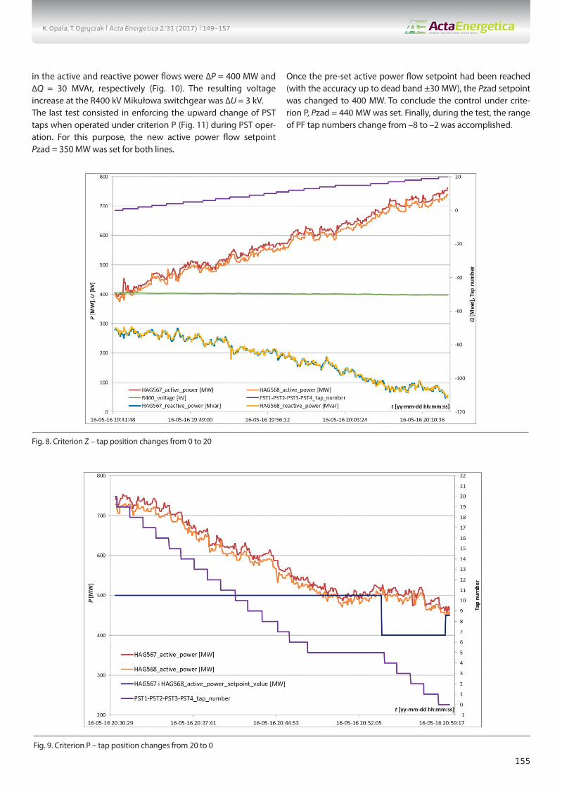
5. Results of phase shifter performance testsThe active power flow control with phase shifting transformers was tested on May 16, 2016 as part of the SSPF acceptance tests. Four PST1–PST4 were operated during the tests. Both HAG567 and HAG568 were operated in parallel – connected to the R400 kV Mikułowa and R380 kV Hagenwerder switchgear.The first test consisted in a change of PSTs taps from 0 to 20 under criterion Z. The test is shown in Fig. 8. The resulting aggre-gate (HAG567 and HAG568) ranges of changes in the active and reactive power flows were 700 MW and 80 MVAr, respectively. The resulting voltage change at the R400 kV Mikułowa switch-gear was 6.5 kV.The next test consisted in changing the criterion from Z to P, and setting power setpoint Pzad = 500 MW for each line. This enforced the reverse change of the PST taps from posi-tion 20 (Fig. 9). Once the expected active power flow had been reached (with the accuracy up to dead band ±30 MW), the setpoint Pzad was changed to 400 MW. This was to force the PST tap position change to the initial zero. When the PST zero tap had been reached, the setpoint Pzad was changed to 450 MW to stop the control under criterion P.Then the control under criterion Z was tested, with negative tap positions (ARS switch position = Retard) from 0 to –10. The resulting aggregate (HAG567 and HAG568) ranges of changes
Fig. 7. Screen of all available SSPF measurements
K. Opala, T. Ogryczak | Acta Energetica 2/31 (2017) | 149–157
155
in the active and reactive power flows were ∆P = 400 MW and ∆Q = 30 MVAr, respectively (Fig. 10). The resulting voltage increase at the R400 kV Mikułowa switchgear was ∆U = 3 kV.The last test consisted in enforcing the upward change of PST taps when operated under criterion P (Fig. 11) during PST oper-ation. For this purpose, the new active power flow setpoint Pzad = 350 MW was set for both lines.
Once the pre-set active power flow setpoint had been reached (with the accuracy up to dead band ±30 MW), the Pzad setpoint was changed to 400 MW. To conclude the control under crite-rion P, Pzad = 440 MW was set. Finally, during the test, the range of PF tap numbers change from –8 to –2 was accomplished.
Fig. 8. Criterion Z – tap position changes from 0 to 20
Fig. 9. Criterion P – tap position changes from 20 to 0
K. Opala, T. Ogryczak | Acta Energetica 2/31 (2017) | 149–157

156
6. SummaryThe installation of four PSTs in the international exchange lines allows efficient control of the active power flow between the grids managed by the Polish grid operator (PSE SA) and the German grid operator (50Hertz). The SSPF system implemented by the Institute of Power Engineering is an effective tool for the
automatic control of the active power flow. In addition, the SSPF monitors the operating status of all PSTs and counteracts the uncontrolled switching operations of HAG567 and HAG568 lines on the Mikułowa substation side.The completed tests allowed verifying the estimated control capacity of the PSTs. Under the test conditions, the average
Fig. 10. Criterion Z – tap position changes from 0 to –10
Fig. 11. Criterion P – tap position changes from –8 to –2
K. Opala, T. Ogryczak | Acta Energetica 2/31 (2017) | 149–157
157
change by. ca. 40 MW/tap and 0.35 kV/tap was achieved. In addi-tion, it has been observed that with an active power flow change also the reactive power flow changes by ca. 10%.The actual conditions and grid constraints did not allow to test the PST control capacity over the full tap adjustment range (from –32 to 32).The test results and the 50Hertz operator’s experience with similar phase shifters in Diele substation are sufficient to adopt linear extrapolation of the obtained characteristics for the remaining PST control range.
REFERENCES
1. Kocot H. et al., “Dobór głównych parametrów przesuwników fazowych dla zachodnich połączeń transgranicznych KSE” [Selection of main parameters of phase shifting transformers for NPS’ western cross-border interconnections], Przegląd Elektrotechniczny, Vol. 90, No. 4, 2014.
2. Korab R., Owczarek R., “Kształtowanie transgranicznych przepływów mocy z wykorzystaniem transformatorów z regulacją poprzeczną” [Control of cross-border power flows with lateral controller transfor-mers], Energetyka, No. 5, 2011.
3. “Performance specification customer order PST PSE Polen”, Maschinenfabrik Reinhausen GmbH, Regensburg, Germany, 2015.
4. “Draft of the futures of the usage of a Tapcon 260 at a phase shifter”, VA TECH Elin Transformatoren GmbH & Co, Weiz, Austria, 2005.
Ksawery OpalaGdańsk Branch of the Institute of Power Engineering
e-mail: [email protected]
Graduated from Gdańsk University of Technology – Faculty of Electrical and Control Engineering and Faculty of Management and Economics. Completed post-graduate
Studies in Nuclear Power Engineering at the Faculty of Electric Engineering and Automatics at his alma mater. Since 2001 a research assistant in the Gdańsk Branch of
the Institute of Power Engineering. His area of interest includes ARNE and ARST automatic control, areal voltage and reactive power control, power grid performance
analysis and flow calculations. He developed the control concept and was involved in the implementation of the Phase Shifter Control System at Mikułowa substation,
and many ARST/ARNE systems in the NPS.
Tomasz OgryczakGdańsk Branch of the Institute of Power Engineering
e-mail: [email protected]
Graduated from Gdańsk University of Technology, Faculty of Electronics, and from post-graduate Studies of Law and Management, Faculty of Management and
Economics. Since 1995 in the Gdańsk Branch of the Institute of Power Engineering, where he deals with the development and implementation of automatic voltage
and reactive control systems for power plants, and transmission and distribution grids. Currently employed as manager of the Power System Automation Department.
He continues his previous research activities, additionally expanded to include innovative power grid operation management support systems, deployment and
management of smart grids and automation systems for wind farms and other renewable energy sources.
K. Opala, T. Ogryczak | Acta Energetica 2/31 (2017) | 149–157

158
PL
Automatyczne sterowanie przesuwnikami fazowymi – możliwości regulacji przepływu mocy czynnej w liniach wymiany międzynarodowej
AutorzyKsawery Opala Tomasz Ogryczak
Słowa kluczoweprzesuwnik fazowy, system sterowania, regulacja przepływu mocy czynnej
StreszczenieAutorzy przedstawili charakterystykę stacji elektroenergetycznej Mikułowa ze względu na jej lokalizację i powiązania sieciowe, skrócony opis funkcjonalny zastosowanej automatyki oraz wyniki badań działania układu automatycznej regulacji czterech przesuwników fazowych zainstalowanych w liniach wymiany międzynarodowej Mikułowa – Hagenwerder. Badania wykonano w ramach prac uruchomieniowych przesuwników fazowych prowadzonych w SE Mikułowa w 2016 roku. Wyniki te pozwalają zweryfikować rzeczywisty zakres regulacji przepływu mocy czynnej pomiędzy systemem elektroenergetycznym Polski i Niemiec oraz wpływ regulacji na rozpływ mocy czynnej w KSE. Jest to pierwsza tego typu instalacja na połączeniu transgranicznym w Polsce. Zmiana przepływu mocy czynnej z wykorzystaniem przesuwników fazowych nie była dotychczas stosowana w Krajowym Systemie Elektroenergetycznym (KSE).
Data wpływu do redakcji: 15.02.2017Data akceptacji artykułu: 27.03.2017Data publikacji online: 30.06.2017
1. WprowadzenieGenezą powstania niniejszego artykułu były doświadczenia praktyczne związane z insta-lacją czterech przesuwników fazowych, o mocy znamionowej 1200 MVA każdy, w stacji elektroenergetycznej Mikułowa. Przesuwniki fazowe o takiej mocy znamio-nowej są urządzeniami, które nie były dotychczas stosowane w KSE. Pracują nato-miast w zagranicznych systemach energe-tycznych, np. w Niemczech – stacja elektro-energetyczna Diele. Przesuwniki fazowe – PF (ang. Phase Shifting Transformer – PST) zainstalowano w dwóch liniach wymiany międzynaro-dowej Mikułowa – Hagenwerder 400 kV, w celu regulacji przepływu mocy czynnej. Zastosowane PF (rys. 1) są praktycznie symetryczne (strona: Source – S i Load – L) i każdy z nich składa się z dwóch osob-nych transformatorów (series – szeregowy i exciter – wzbudzający). Transformator wzbudzający TW ma oba uzwojenia połączone w gwiazdę. Uzwojenie pierwotne TW jest zasilane z sieci, a uzwo-jenie wtórne współpracuje z przełącznikiem zaczepów pod obciążeniem. Uzwojenie wtórne transformatora szeregowego TS, wytwarzające napięcie dodawcze, jest włączone w szereg z linią, w której regu-luje się przesunięcie fazowe napięcia. Przez uzwojenie przepływa pełny prąd linii. Uzwojenie pierwotne TS jest natomiast połączone w trójkąt (co zapewnia przesu-nięcie napięć o π/2) i jest zasilane z uzwo-jenia regulacyjnego transformatora wzbu-dzającego [1]. Regulacja przepływu mocy czynnej przez przesuwniki fazowe polega na zmianie rozpływu bez zmiany sumarycznej mocy wytwarzanej w sieci. Wykorzystana jest tutaj znana zależność określająca prze-pływ mocy czynnej przez pojedynczą gałąź
o charakterze indukcyjnym. Ma ona nastę-pującą postać [2]:
(1)
gdzie: P – moc czynna wypływająca z rozpa-trywanej gałęzi, Ui, Uj – moduły napięć na początku i końcu gałęzi, δ – kąt obcią-żenia (różnica argumentów napięć węzło-wych na początku i końcu gałęzi, δ = δi – δj).Regulacja przepływu mocy czynnej przez przesuwniki fazowe polega na zmianie wartości kąta obciążenia poprzez zmianę numeru zaczepu w uzwojeniu wtórnym TW. Zainstalowane w SE Mikułowa PF posiadają 65 stopni regulacji (±32 zaczepy), dzięki którym możliwa jest zmiana wartości, jak i kierunku mocy czynnej płynącej w linii MIK-HAG (Mikułowa–Hagenwerder).PF posiadają dwa przełączniki zaczepów firmy Reinhausen współpracujące ze sobą. Pierwszy przełącznik OLTC (On-Load Tap Changer) zmienia położenie numeru zaczepu w zakresie 0… 32 i jest zlokalizo-wany przy TW (rys. 1). Natomiast drugi przełącznik ARS (Advance Retard Switch) odpowiada za poszerzenie zakresu regula-cyjnego z Advance – kierunek zwiększania importu mocy czynnej na Retard – wzrost eksportu. Kierunki i wartość przepływu mocy czynnej w zależności od zmian poło-żenia przełączników zaczepów ARS i OLTC przedstawiono na rys. 2.Aby zmienić kierunek Advance/Retard należy zmieniać zaczep PPZ stopniowo o jeden, w kierunku zaczepu 0. Zmiana kierunku sterowania Advance/Retard nastąpi automatycznie w chwili przej-ścia przez PPZ z pozycji 0R na 1A lub 0A na 1R [3]. Należy kontynuować zmianę zaczepów PPZ aż do osiągnięcia żądanej pozycji PPZ.
2. Charakterystyka węzła Mikułowa (MIK)Stacja elektroenergetyczna Mikułowa 400/220/110 kV jest położona przy granicy polsko-niemieckiej w pobliżu Elektrowni Turów (ok. 30 km). Stacja połączona jest bezpośrednio dwoma liniami 400 kV (o długości 36 km) ze stacją niemiecką Hagenwerder. W torze linii, oznaczonej jako HAG567, zainstalowano szeregowo dwa przesuwniki fazowe PF1 i PF2. Analogicznie w torze linii HAG568 zainstalowano szere-gowo dwa przesuwniki fazowe PF3 i PF4. Rozdzielnia 400 kV połączona jest również pojedynczą linią za stacją Czarna (rys. 3). Aktualnie do rozdzielni 220 kV przyłą-czone są generatory: G2, G3, G4, G5, G6, natomiast do rozdzielni 110 kV Elektrowni Turów przyłączony jest generator G1.W s t a c j i e l e k t r o e n e r g e t y c z n e j 400/220/110 kV Mikułowa pracują: auto-transformatory AT1 i AT2 400/220 kV o mocy znamionowej Sn = 500 MVA oraz autotransformatory AT3 i AT4 220/110 kV o mocy znamionowej Sn = 160 MVA. W stacji pracują także przesuwniki fazowe oznaczone jako TD1 i TD2 o mocy znamio-nowej Sn = 500 MVA. TD1 i TD2 zlokali-zowane są po stronie dolnego uzwojenia 220 kV autotransformatorów odpowiednio AT1 i AT2.
3. System sterowania przesuwników fazowych SSPF SSPF monitoruje stan topologii linii 567 i 568 oraz sprzęgła SP w stacji Mikułowa (rys. 4) i dobiera sposób działania do aktual-nego stanu pracy (łączniki, pomiary z prze-kładników prądowych i napięciowych). Obwody pomiarów prądowych i napięcio-wych oraz odwzorowania stanu położenia łączników koniecznych do poprawnej pracy układu są doprowadzone bezpośrednio do SSPF (rys. 5). Podobnie sterowanie
This is a supporting translation of the original text published in this issue of “Acta Energetica” on pages 149–157. When referring to the article please refer to the original text.
K. Opala, T. Ogryczak | Acta Energetica 2/31 (2017) | translation 149–157

159
PL
zmianą zaczepów przesuwników PF1 – PF4 realizowane jest bezpośrednio poprzez styki wyjściowe SSPF [4].SSPF jest źródłem sygnałów zezwalających na załączenie linii 567 i 568 oraz sprzęgła, które są wykorzystywane przez system SSiN. Z powodów zewnętrznych problemów technicznych SSPF nie dysponuje pomia-rami i odwzorowaniami ze strony stacji Hagenwerder. Z tego powodu przyjęto, że linie HAG567 i HAG568 są stale połą-czone w rozdzielni 380 kV Hagenwerder.Parametry regulacji: • EpsP – strefa nieczułości wartości zadanej
mocy czynnej Pzad• DeadTime – okres czasu [s], na który
zatrzymana jest praca automatyczna SSPF• RatioDiff – dopuszczalna różnica prze-
kładni pomiędzy liniami• UnderVLock value – wartość blokady
podnapięciowej• OverVLock value – wartość blokady
nadnapięciowej• OvecurrentLock value – wartość blokady
nadprądowej. Zadania regulacyjne realizowane są przez system w oparciu o parametry regulacji zadawane lokalnie z terminalu SSPF lub terminalu systemu komputerowego SSiN stacji, czy też zdalnie z poziomu ODM/KDM za pomocą systemu DYSTER. Terminal SSPF w stacji służy do miejscowego wpro-wadzania wartości zadanych procesu regu-lacji, sterowania oraz graficznej prezentacji działania procesu regulacji SSPF. Prezentacja wyników na uproszczonym schemacie funk-cjonalnym SSPF (ekran regulacji SSPF – rys. 6) polega na wyświetlaniu bieżących wartości napięć, mocy, numerów zaczepów, pozycji ARS, wartości zadanych, komuni-katów i sygnalizacji. Szczegółowe odczyty pomiarów z przekładników w poszczegól-nych polach umieszczone są na ekranie pomiarów (rys. 7).Zdalne sterowanie i nadzór nad działaniem SSPF realizowany jest z poziomu ODM/KDM za pomocą systemu DYSTER poprzez terminal o takiej samej funkcjonalności w zakresie obsługi SSPF, jak terminal lokalny w stacji.Połączenie systemu SSPF stacji z SSiN jest redundantne i umożliwia przekazywanie danych związanych z procesem regulacji oraz pobieranie danych z SSiN w zakresie wartości zadanych dla procesu regulacji. Poprzez SSiN realizowana jest komunikacja z ośrodkami nadrzędnymi ODM/KDM.
4. Opis działania SSPFSystem SSPF przeznaczony jest do automa-tycznego prowadzenia ruchu SE Mikułowa w następującym zakresie:• utrzymywanie zadanego poziomu mocy
czynnej przepływającej przez przesuwniki fazowe stacji – kryterium P
• sterowanie zaczepami przesuw-ników fazowych (ustawianie zada-nego numeru zaczepu przesuw-nika i/lub realizacja sterowań zaczep w górę/ dół) – kryterium Z.
Nie dopuszcza się asymetrycznej pracy PF (1-0, 2-0 i 2-1) w trybie automatycznej regu-lacji SSPF. Kryterium P (wg zadanej mocy czynnej Pzad) jest podstawowym warun-kiem pracy automatycznej. W kryterium P zadaniem systemu sterowania (SSPF) jest
Rys. 1. Schemat połączeń pomiędzy TW i TS przesuwnika fazowego produkcji Siemens Weiz, zastosowanego w SE Mikułowa [3]
Rys. 2. Sterowanie przełącznikiem zaczepów w celu regulacji przepływu mocy czynnej. Stąd maksymalny import mocy czynnej można uzyskać w położeniu 32A, a maksymalny eksport w położeniu 32R
This is a supporting translation of the original text published in this issue of “Acta Energetica” on pages 149–157. When referring to the article please refer to the original text.
K. Opala, T. Ogryczak | Acta Energetica 2/31 (2017) | translation 149–157

160
PL
utrzymanie zadanej mocy czynnej Pzad dla węzła MIK oraz utrzymywanie odpo-wiednich przepływów w linach 400 kV MIK-HAG, np. unikanie wystąpienia krążenia mocy.Nie dopuszcza się pracy PF z różnymi trybami regulacji automatycznej (SSPF) i ręcznej (bez SSPF). Gdy zaistnieje taki przypadek, to PF, który jest w trybie pracy automatycznej, pozostanie wyłączony z pracy automatycznej przez SSPF. Przykład: Obydwa PF załączone do pracy automa-tycznej w danej linii; jeżeli następnie jeden z nich zostanie przełączony do pracy ręcznej, to praca automatyczna drugiego zostanie zablokowana.System SSPF wykrywa niepożądane stany pracy przesuwników fazowych pracujących w linii HAG 567 i HAG 568. Po wykryciu takich stanów SSPF generuje przedstawione poniżej sygnały ostrzeżeń (rys. 7):1. N i e s y m e t r y c z n a p r a c a l i n i i
HAG567/568 – informacja o niesyme-trycznej (1-0, 2-0, 2-1) pracy linii HAG 567 i HAG 568
2. Niesymetryczna konfiguracja linii HAG567 – informacja o niesymetrii wyłączonej linii HAG 567 w stosunku do załączonej linii HAG 568
3. Niesymetryczna konfiguracja linii HAG568 – informacja o niesymetrii wyłączonej linii HAG 568 w stosunku do załączonej linii HAG 567
4. Pr z e k ro c z en i e R at i o D i f f d l a HAG567/568 – informacja o suma-rycznym rozstrojeniu zaczepów pomiędzy liniami
5. Przekroczenie RatioDiff dla PF1-PF2 – informacja o rozstrojeniu zaczepów prze-suwników PF1 i PF2 (w linii HAG 567)
6. Przekroczenie RatioDiff dla PF3-PF4 – informacja o rozstrojeniu zaczepów prze-suwników PF3 i PF4 (w linii HAG 568).
Zasady pracy SSPF w kryterium ZSSPF umożliwia zmianę pozycji PPZ na przesuwnikach poprzez zadawanie numeru zaczepu lub sterowanie strzał-kami zaczep w górę / zaczep w dół. Zakres nastawień zadanych numerów zaczepów PPZ wynosi od –32 do +32 (od 32 Retard do 32 Advance).
Rys. 3. Topologia węzła regulacyjnego MIK
Rys. 4. Przekładniki prądowe i napięciowe oraz łączniki, których stan doprowadzony jest do SSPF
Rys. 5. Konfiguracja sprzętowa SSPF
This is a supporting translation of the original text published in this issue of “Acta Energetica” on pages 105–110. When referring to the article please refer to the original text.This is a supporting translation of the original text published in this issue of “Acta Energetica” on pages 149–157. When referring to the article please refer to the original text.
K. Opala, T. Ogryczak | Acta Energetica 2/31 (2017) | translation 149–157

161
PL
Układ SSPF (dla pracy wszystkich PF) wyko-nuje sterowania sekwencyjne jednocześnie parami: PF1 i PF3 oraz PF2 i PF4. 1. W układzie pracy jednej linii HAG 567
lub 568, w przypadku zmiany zaczepów wykonywanej przez zadawanie numeru zaczepów na jednym z przesuwników w danej linii, układ SSPF powoduje prze-pisanie tej samej wartości zadanej także dla drugiego przesuwnika w tej linii.
2. W układzie pracy obu linii HAG 567 i 568, w przypadku zmiany zaczepów wykonywanej przez zadawanie numeru zaczepów na jednym z przesuwników w jednej z linii, układ SSPF powoduje przepisanie tej samej wartości zadanej także dla wszystkich pozostałych prze-suwników w obu torach linii.
3. Zmianę zaczepów strzałkami zaczep w górę / zaczep w dół wykonuje się indy-widulanie na każdym z przesuwników z osobna. Zmiana numeru zaczepu wyko-nana w ten sposób powoduje także zmianę wartości zadanej danego przesuwnika.
4. Układ SSPF uniemożliwia zadanie numeru zaczepów większej niż zmiana o jeden zaczep – zmiana o więcej numerów zaczepów wymaga kolejno zadawania wartości większej o jeden numer od bieżącego zaczepu.
Zasady pracy układu SSPF w kryterium PUkład SSPF umożliwia zmianę aktualnego przesyłu mocy czynnej w liniach HAG567 i HAG568 poprzez zadawanie wartości mocy Pzad. Zakres zadawania wartości mocy wynosi od –1170 MW do +1170 MW. Moc zadana przypisana jest do każdej z linii HAG567 i HAG568 (rys. 6). W przypadku pracy równoległej linii wprowadzenie nowej wartości zadanej dla jednej z linii powoduje przepisanie tej wartości zadanej dla drugiej linii.Rzeczywista wartość mocy przepływającej przez linię (przesuwniki) może się różnić od zadanej o wartość strefy nieczułości układu SSPF, która wynosi epsP +/– 30 MW. Np. dla wartości zadawanej mocy 1170 MW wynikowa moc przepływająca przez prze-suwnik będzie się zawierać w zakresie od 1140 MW do 1200 MW.Aby zmienić kierunek przepływu mocy czynnej, należy zadać wartości mocy z odpowiednim znakiem, odpowiednio „+” dla mocy importowanej i „–” dla mocy eksportowanej.Układ SSPF zmienia pozycje zaczepów co jeden zaczep w kierunku osiągnięcia nasta-wionej zadanej wartości mocy. Zmiana kierunku sterowania Advance/Retard nastę-puje automatycznie w chwili przełączenia przez PPZ zaczepu z 0R na 1A lub z 0A na 1R. Następnie układ SSPF kontynuuje zmianę zaczepów PPZ aż do osiągnięcia zadanej wartości mocy.Układ SSPF (dla pracy wszystkich PF) wyko-nuje sterowania sekwencyjne jednocześnie parami: PF1 i PF3 oraz PF2 i PF4, zmieniając w jednym kroku pozycję o jeden zaczep.
5. Wyniki badań pracy przesuwników fazowychPróbę regulacji przepływu mocy czynnej z wykorzystaniem przesuwników fazowych wykonano 16 maja 2016 roku w ramach
Rys. 6. Ekran regulacji SSPF
Rys. 7. Ekran wszystkich dostępnych pomiarów SSPF
Rys. 8. Kryterium Z – zakres zmiany zaczepów od 0 do 20
This is a supporting translation of the original text published in this issue of “Acta Energetica” on pages 105–110. When referring to the article please refer to the original text.This is a supporting translation of the original text published in this issue of “Acta Energetica” on pages 149–157. When referring to the article please refer to the original text.
K. Opala, T. Ogryczak | Acta Energetica 2/31 (2017) | translation 149–157

162
PL
testów odbiorczych układu SSPF. Podczas prób pracowały cztery przesuwniki PF1 – PF4. Obie linie HAG567 i HAG568 praco-wały równolegle – połączone w rozdzielni R400 kV Mikułowa oraz R380 kV Hagenwerder. Pierwsza próba polegała na zmianie w kryterium Z zaczepów PF od wartości 0 do 20. Przebieg próby zaprezentowano na rys. 8. Uzyskany sumaryczny (linia HAG567 i HAG568) zakres zmian prze-pływu mocy czynnej wynosi 700 MW, mocy biernej 80 Mvar. Zmiana wartości napięcia na rozdzielni R400 kV Mikułowa wyniosła 6,5 kV.Kolejna próba polegała na zmianie kryte-rium z Z na P i wymuszeniu wartości zadanej Pzad = 500 MW dla każdej z linii. Dzięki temu wymuszono powrotną zmianę zaczepów PF z pozycji 20 (rys. 9). Po osią-gnięciu oczekiwanej wartości przepływu mocy czynnej (z dokładnością do strefy nieczułości ±30 MW) dokonano zmiany Pzad na 400 MW. Miało to na celu wymu-szenie osiągnięcia przez PF wyjściowej pozycji zerowej zaczepów. Po uzyskaniu zerowego zaczepu przez PF zmieniono wartość Pzad na 450 MW, aby przerwać regulację w kryterium P.Następnie przeprowadzono próbę regulacji w kryterium Z w zakresie zaczepów ujem-nych (pozycja przełącznika ARS = Retard) od 0 do –10. Osiągnięto sumaryczną (w obu liniach) zmianę przepływu mocy czynnej ∆P = 400 MW oraz mocy biernej ∆Q = 30 Mvar (rys. 10). Uzyskany podczas próby przyrost napięcia dla rozdzielni R400 Mikułowa wyniósł ∆U = 3 kV.Ostatnia próba polegała na wymuszeniu podczas pracy PF w kryterium P zmiany zaczepów w górę (rys. 11). W tym celu przy-jęto nową wartość zadaną przepływu mocy czynnej (dla obu linii) Pzad = 350 MW. Po osiągnięciu zadanej wartości przepływu mocy czynnej (z dokładnością do strefy nieczułości ±30 MW) dokonano zmiany Pzad na 400 MW. W celu zakończenia regu-lacji, w kryterium P przyjęto Pzad = 440 MW. Ostatecznie podczas próby osiągnięto zakres zmian numerów zaczepów PF od –8 do –2.
6. PodsumowanieInstalacja czterech PF w liniach wymiany międzynarodowej pozwala na skuteczne kształtowanie poziomu przepływu mocy czynnej, pomiędzy sieciami zarządzanymi przez operatora sieci polskiej (PSE SA) i niemieckiej (50Hertz). Wdrożony przez Instytut Energetyki układ SSPF jest skutecznym narzędziem pozwalającym na prowadzenie automatycznej regulacji przepływu mocy czynnej. Dodatkowo SSPF kontroluje stan pracy wszystkich PF oraz przeciwdziała niekontrolowanym opera-cjom łączeniowym linii HAG567 i HAG568 po stronie SE Mikułowa. Przeprowadzone próby pozwoliły urealnić szacowane dotąd możliwości regulacyjne zainstalowanych PF. W badanych warun-kach osiągnięto średnią zmianę ok. 40 MW/zaczep i 0,35 kV/ zaczep. Dodatkowo zaob-serwowano, że zmiana wartości przepływu mocy czynnej wywołuje ok. 10-proc. zmianę przepływu mocy biernej.
Rys. 9. Kryterium P – zakres zmiany zaczepów od 20 do 0
Rys. 11. Kryterium P – zakres zmiany zaczepów od –8 do –2
Rys. 10. Kryterium Z – zakres zmiany zaczepów od 0 do –10
This is a supporting translation of the original text published in this issue of “Acta Energetica” on pages 105–110. When referring to the article please refer to the original text.This is a supporting translation of the original text published in this issue of “Acta Energetica” on pages 149–157. When referring to the article please refer to the original text.
K. Opala, T. Ogryczak | Acta Energetica 2/31 (2017) | translation 149–157
163
PL
Bieżące warunki i ograniczenia sieciowe nie pozwoliły na zbadanie możliwości regulacji PF w pełnym zakresie regulacji (od zaczepu –32 do 32). Wyniki z prób oraz doświad-czenia operatora 50Hertz z podobnymi przesuwnikami w SE Diele są wystarczające do przyjęcia liniowej ekstrapolacji uzyska-nych charakterystyk dla pozostałego zakresu regulacji PF.
Bibliografia
1. Kocot H. i in., Dobór głównych parame-trów przesuwników fazowych dla zachod-nich połączeń transgranicznych KSE, Przegląd Elektrotechniczny 2014, r. 90, nr 4.
2. Korab R., Owczarek R., Kształtowanie transgranicznych przepływów mocy z wykorzystaniem transformatorów
z regulacją poprzeczną, Energetyka 2011, nr 5.
3. Performance specification customer order PST PSE Polen, Maschinenfabrik Reinhausen GmbH, Regensburg, Germany, 2015.
4. Draft of the futures of the usage of a Tapcon 260 at a phase shifter, VA TECH Elin Transformatoren GmbH & Co, Weiz, Austria, 2005.
Ksawery Opala mgr inż.Instytut Energetyki Instytut Badawczy Oddział Gdańske-mail: [email protected] Absolwent studiów magisterskich na Politechnice Gdańskiej – Wydział Elektrotechniki i Automatyki oraz Wydział Zarządzania i Ekonomii. Ukończył podyplomowe Studium Energetyki Jądrowej na Wydziale Elektrotechniki i Automatyki macierzystej uczelni. Od 2001 roku jest zatrudniony w Instytucie Energetyki Oddział Gdańsk na stanowisku asystenta. Obszar zainteresowań obejmuje automatykę regulacyjną ARNE i ARST, obszarową regulację napięcia i mocy biernej, analizy stanu pracy sieci elektroenergetycznej i obliczenia rozpływowe. Opracował koncepcję regulacji oraz zajmował się wdrożeniem Systemu Sterownia Przesuwnikami Fazowymi Mikułowa oraz wielu układów ARST/ARNE w KSE.
Tomasz Ogryczak mgr inż.Instytut Energetyki Instytut Badawczy Oddział Gdańske-mail: [email protected] Absolwent Politecniki Gdańskiej – ukończył studia magisterskie na Wydziale Elektroniki oraz podyplomowe Studium Prawno-Menedżerskie na Wydziale Zarządzania i Ekonomii. Od 1995 roku pracuje w Instytucie Energetyki Oddział Gdańsk, gdzie zajmuje się rozwojem i wdrażaniem układów automatycznej regulacji napięcia i mocy biernej stosowanych w elektrowniach, sieci przesyłowej oraz w sieciach dystrybucyjnych. Obecnie jest zatrudniony na stanowisku kierownika Zakładu Automatyki Systemów Elektroenergetycznych. Kontynuuje dotychczasową działalność dodatkowo rozszerzoną o innowacyjne systemy wspomagania prowadzenia ruchu sieci energetycznych, zagadnienia związane z wdrażaniem i zarządzaniem sieciami inteligentnymi oraz układami automa-tyki dla farm wiatrowych i innych odnawialnych źródeł energii.
This is a supporting translation of the original text published in this issue of “Acta Energetica” on pages 105–110. When referring to the article please refer to the original text.This is a supporting translation of the original text published in this issue of “Acta Energetica” on pages 149–157. When referring to the article please refer to the original text.
K. Opala, T. Ogryczak | Acta Energetica 2/31 (2017) | translation 149–157