Automated Steering System of Tractor and Other Self ...
14
Automated Steering System of Tractor and Other Self- propelled Agricultural Machineries, Using Visible Cable M.H. Aghkhani 1 ; M.H. Abbaspour-fard 1 ; I. Saedi 1 1 Dept. of Farm Machinery Engineering, College of Agriculture, Ferdowsi University of Mashhad, IRAN Corresponding author: M.H. Aghkhani Tel: 00989153114106 H U ir . ac . um @ aghkhani U [email protected] 57
Transcript of Automated Steering System of Tractor and Other Self ...
Automated Steering System of Tractor and Other Self-propelled Agricultural Machineries, Using Visible Cable
M.H. Aghkhani1; M.H. Abbaspour-fard1; I. Saedi1
1 Dept. of Farm Machinery Engineering, College of Agriculture, Ferdowsi University of Mashhad, IRAN
Corresponding author:
M.H. Aghkhani
Tel: 00989153114106
HUir .ac.um@aghkhaniU [email protected]
57

Abstract:
There have been numerous works dealing with precise and automated steering of off-
road vehicles and agricultural machineries, but due to drawbacks such as cost and
technological limitations, they mostly have not been welcomed or popularized. In this
study, an interchangeable system, with fairly low cost, and moderate technological
requirements was developed, constructed and tested which can be installed on most
agricultural tractors, and other off-road, self-propelled machineries. The system
comprised of a cable-spreading unit with a slim steel cable, a fifth-wheel (or ground-
wheel) with some cable-positioning sensors, a control unit and processor along with an
electro-mechanical steering wheel driver. To steer on a predefined path, the vehicle
should be initially steered manually on the first path. On subsequent pass, automatic
steering is obtained by putting the fifth-wheel on the previously put down-cable. A
prototype of this system was fabricated and installed on a MF285 tractor with
intentional accuracy of ± 2.5 centimeters. The overall offset deviation (error) from the
desired path was ± 2.6 cm/m and ± 2.4 cm/m of longitudinal path, on soil and asphalt
surfaces, respectively. However, this can be diminished through design characteristics
modification such as using a narrower position sensors. In large fields and long paths,
an accurate steering with the least tiredness, as well as more attention on implement
adjustments and performance instead of vehicle driving would be achieved.
Keywords: automated steering, off-road vehicles, self-propelled machinery.
58
Introduction: Automated steering of vehicles has always been a great hope of human beings. In this regard, the automated steering of mobile agricultural machines attached to tractors has the most importance and preference. This is mainly due to simultaneous driving and attention on implement adjustments and overall performances as well as experiencing harsh fields’ conditions. Furthermore, precise field steering of agricultural machinery would directly affect on overall efficiency and production improvement as well as primary resources saving. This is of much more importance in planting equipments. Precise steering of planting machineries would ensures optimal utilization of land, water, seed and fertilizers in addition to providing best conditions for plant growth and also precise operation of subsequent equipments. Since there is no mark on recently tilled fields, precise steering of planting equipments is much more difficult. Currently, the operator follows the planting pattern by steering the tractor in such a manner the middle of supposed tractor or one of its front wheel lies on the groove (guide path) previously generated by marker, so parallel trajectories with predefined distance would be achieved. However, the guiding performance of operator on the marked path is affected by path width, the front wheel width, operator's tiredness beside simultaneous awareness on both forward movement and the implement performance. Therefore, lack of operator guiding performance results in row width alteration, which in turn leads to both land wastage, and, production efficiency reduction. Moreover, any deviation from optimal row width will encounter the operation of succeeding machineries such as cultivators and harvesters (specifically beet-like harvesters) with some difficulties and also the associated land and yield wastes. Several attempts have been made in laboratory scale for automatic or semi-automatic steering of agricultural machinery, but for some reasons none of them were commercially developed. The first design for tractor steering was patented by Willrodt [13]. In this plan, tractor was steered by means of a mechanical system (in-furrow movements of a wheel) which activated via a transmitted mechanical command. Kirk [10] developed a tractor automated steering system based on “furrow trace”. A furrow was generated at the first path by a furrower installed on a tractor or a farm machine. This design was similar to Willrodt’s in all aspects but the steering wheel activated through an electromechanical mechanism. Clockwise or anti-clockwise turning of electromotor installed on steering rod was actuated through a mechanical sensor with a two-way switch. This system was efficient enough, but the problem of making furrow on soil limited it only to tillage processes. Also, installing a furrower at the right side of tractor or farm machine needs further arrangements (Fig.1a). The idea of using hidden (buried) cable for automatic steering of machinery was first proposed by Brook [6], which was then taken into consideration by others. In this system the hidden cables with a low current are buried in predetermined distances in subsurface soil. An electro magnetic sensor senses the magnetic field generated around the cable, so commanded the steering system to trace the cable (Fig.1b).
59
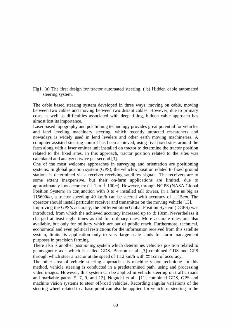
Fig1. (a) The first design for tractor automated steering, ( b) Hidden cable automated steering system.
The cable based steering system developed in three ways: moving on cable, moving between two cables and moving between two distant cables. However, due to primary costs as well as difficulties associated with deep tilling, hidden cable approach has almost lost its importance. Laser based topography and positioning technology provides great potential for vehicles and land leveling machinery steering, which recently attracted researchers and nowadays is widely used in lend levelers and other earth moving machineries. A computer assisted steering control has been achieved, using five fixed sites around the farm along with a laser emitter unit installed on tractor to determine the tractor position related to the fixed sites. In this approach, tractor position related to the sites was calculated and analyzed twice per second [3]. One of the most welcome approaches in surveying and orientation are positioning systems. In global position system (GPS), the vehicle's position related to fixed ground stations is determined via a receiver receiving satellites' signals. The receivers are to some extent inexpensive, but their on-farm applications are limited, due to approximately low accuracy ( 1 to ± ± 100m). However, through NGPS (NASA Global Position System) in conjunction with 3 to 4 installed tall towers, in a farm as big as 115600ha, a tractor speeding 40 km/h can be steered with accuracy of ± 15cm. The operator should install particular receiver and transmitter on the moving vehicle [13]. Improving the GPS’s accuracy, the Differentiation Global Position System (DGPS) was introduced, from which the achieved accuracy increased up to ± 10cm. Nevertheless it charged at least eight times as did for ordinary ones. More accurate ones are also available, but only for military which are out of public reach. Furthermore, technical, economical and even political restrictions for the information received from this satellite system, limits its application only to very large scale lands for farm management purposes in precision farming. There also is another positioning system which determines vehicle's position related to geomagnetic axis which is called GDS. Benson et al. [3] combined GDS and GPS through which steer a tractor at the speed of 1.12 km/h with ± 1cm of accuracy. The other area of vehicle steering approaches is machine vision technique. In this method, vehicle steering is conducted in a predetermined path, using and processing video images. However, this system can be applied in vehicle steering on traffic roads and markable paths [5, 7, 9, and 12]. Noguchi et al. [11] combined GDS, GPS and machine vision systems to steer off-road vehicles. Recording angular variations of the steering wheel related to a base point can also be applied for vehicle re-steering in the
60
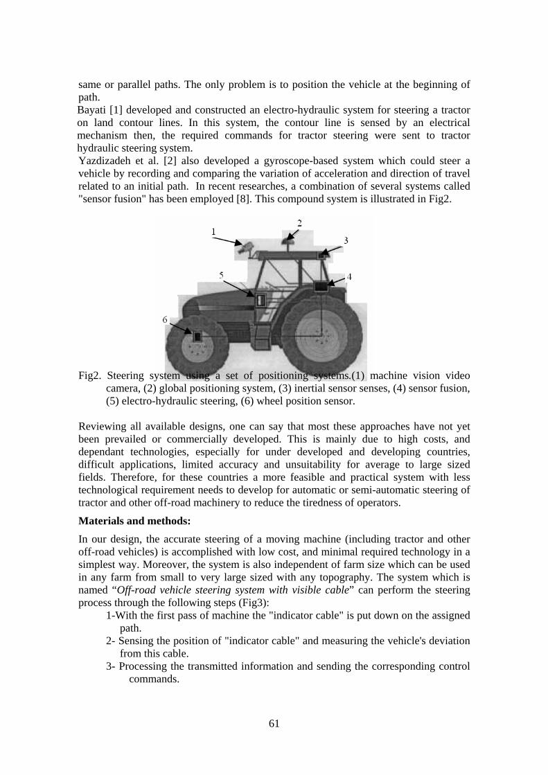
same or parallel paths. The only problem is to position the vehicle at the beginning of path. Bayati [1] developed and constructed an electro-hydraulic system for steering a tractor on land contour lines. In this system, the contour line is sensed by an electrical mechanism then, the required commands for tractor steering were sent to tractor hydraulic steering system. Yazdizadeh et al. [2] also developed a gyroscope-based system which could steer a vehicle by recording and comparing the variation of acceleration and direction of travel related to an initial path. In recent researches, a combination of several systems called "sensor fusion" has been employed [8]. This compound system is illustrated in Fig2.
Fig2. Steering system using a set of positioning systems.(1) machine vision video
camera, (2) global positioning system, (3) inertial sensor senses, (4) sensor fusion, (5) electro-hydraulic steering, (6) wheel position sensor.
Reviewing all available designs, one can say that most these approaches have not yet been prevailed or commercially developed. This is mainly due to high costs, and dependant technologies, especially for under developed and developing countries, difficult applications, limited accuracy and unsuitability for average to large sized fields. Therefore, for these countries a more feasible and practical system with less technological requirement needs to develop for automatic or semi-automatic steering of tractor and other off-road machinery to reduce the tiredness of operators.
Materials and methods: In our design, the accurate steering of a moving machine (including tractor and other off-road vehicles) is accomplished with low cost, and minimal required technology in a simplest way. Moreover, the system is also independent of farm size which can be used in any farm from small to very large sized with any topography. The system which is named “Off-road vehicle steering system with visible cable” can perform the steering process through the following steps (Fig3):
1-With the first pass of machine the "indicator cable" is put down on the assigned path.
2- Sensing the position of "indicator cable" and measuring the vehicle's deviation from this cable.
3- Processing the transmitted information and sending the corresponding control commands.
61
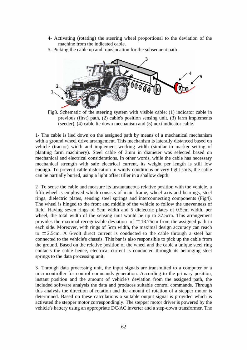
4- Activating (rotating) the steering wheel proportional to the deviation of the machine from the indicated cable.
5- Picking the cable up and translocation for the subsequent path.
3
Fig3. Schematic of the steering system with visible cable: (1) indicator cable in
previous (first) path, (2) cable's position sensing unit, (3) farm implements (seeder), (4) cable lie down mechanism and (5) next indicator cable.
1- The cable is lied down on the assigned path by means of a mechanical mechanism with a ground wheel drive arrangement. This mechanism is laterally distanced based on vehicle (tractor) width and implement working width (similar to marker setting of planting farm machinery). Steel cable of 3mm in diameter was selected based on mechanical and electrical considerations. In other words, while the cable has necessary mechanical strength with safe electrical current, its weight per length is still low enough. To prevent cable dislocation in windy conditions or very light soils, the cable can be partially buried, using a light offset tiller in a shallow depth. 2- To sense the cable and measure its instantaneous relative position with the vehicle, a fifth-wheel is employed which consists of main frame, wheel axis and bearings, steel rings, dielectric plates, sensing steel springs and interconnecting components (Fig4). The wheel is hinged to the front and middle of the vehicle to follow the unevenness of field. Having seven rings of 5cm width and 5 dielectric plates of 0.5cm width, per wheel, the total width of the sensing unit would be up to 37.5cm. This arrangement provides the maximal recognizable deviation of ± 18.75cm from the assigned path in each side. Moreover, with rings of 5cm width, the maximal design accuracy can reach to 2.5cm. A 6-volt direct current is conducted to the cable through a steel bar connected to the vehicle's chassis. This bar is also responsible to pick up the cable from the ground. Based on the relative position of the wheel and the cable a unique steel ring contacts the cable hence, electrical current is conducted through its belonging steel springs to the data processing unit.
±
3- Through data processing unit, the input signals are transmitted to a computer or a microcontroller for control commands generation. According to the primary position, instant position and the amount of vehicle's deviation from the assigned path, the included software analysis the data and produces suitable control commands. Through this analysis the direction of rotation and the amount of rotation of a stepper motor is determined. Based on these calculations a suitable output signal is provided which is activated the stepper motor correspondingly. The stepper motor driver is powered by the vehicle's battery using an appropriate DC/AC inverter and a step-down transformer. The
5
4
1 2
62

current needed for the computer and the input current to the cable is also supplied in like manner. In the primary laboratory design of the system a laptop was employed to get the optimal adjustments. The provision was made to replace the laptop with a microcontroller, subsequent to the primary experimental methods of the system. The software is also transferred (programmed) to the microcontroller. The fifth-wheel and its components are shown schematically in Fig4 and the flow diagram of the control circuit is also illustrated in Fig6. A 6-volt current is entered to the lied-down cable through a steel bar, then passed on to the steel springs and finally conducted to the circuit input port (3 in Fig5) and then to the processing unit.
Fig4. Fifth-wheel. a) Virtual figure and components: 1- fixed chassis, 2- hinged frame, 3- Teflon circular plates, 4- steel drums, 5- Teflon rod for supporting the connecting springs, 6- steel springs, 7- steel supporting disks, 8- bearing, 9- rotating shaft.
a b
b) Actual figure.
Fig5. Flow diagram of control circuit: (1) lied-down cable, (2) fifth-wheel and its position sensors, (3) input port and the middle circuit, (4) processing unit (computer or microcontroller), (5) power supply unit, (6) stepper motor driver,(7) stepper motor, (8) steering wheel and its belt drive mechanism, (9) electrical current path, (10) control current path.
Subsequent to data processing (No. 4 in Fig5) the instant relative position of the vehicle with the optimal path (predefined) is determined and accordingly an appropriate control command for activating the stepper motor driver is generated (No. 6 in Fig5) and then enters to the steering driver section through exit-port of the circuit. The required electrical current is prepared in electrical power supply unit (No. 5 in Fig5). At the first stage, 12v DC of the vehicle's battery is inverted to 220v AC. This was mainly due to laptop electrical requirement. To provide the activation current for the stepper motor,
63
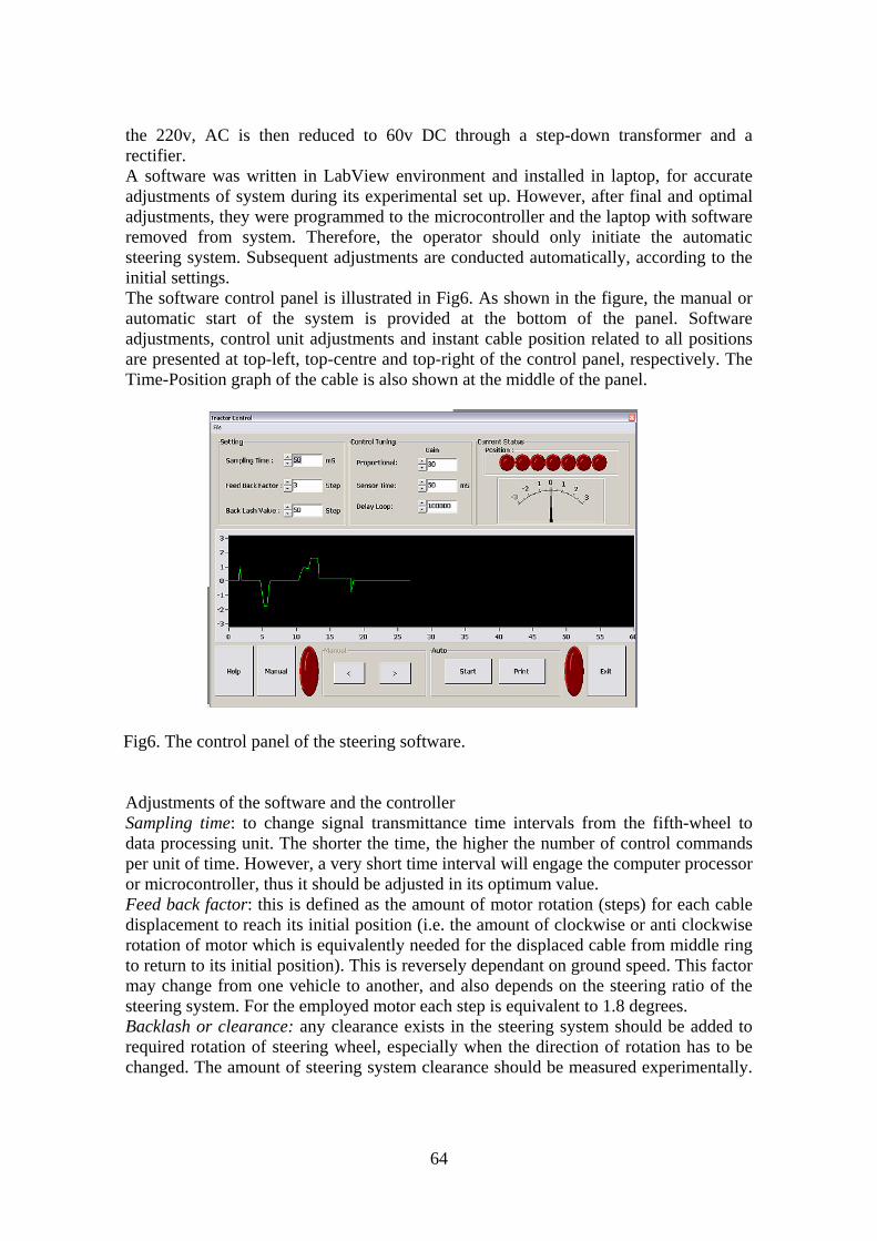
the 220v, AC is then reduced to 60v DC through a step-down transformer and a rectifier. A software was written in LabView environment and installed in laptop, for accurate adjustments of system during its experimental set up. However, after final and optimal adjustments, they were programmed to the microcontroller and the laptop with software removed from system. Therefore, the operator should only initiate the automatic steering system. Subsequent adjustments are conducted automatically, according to the initial settings. The software control panel is illustrated in Fig6. As shown in the figure, the manual or automatic start of the system is provided at the bottom of the panel. Software adjustments, control unit adjustments and instant cable position related to all positions are presented at top-left, top-centre and top-right of the control panel, respectively. The Time-Position graph of the cable is also shown at the middle of the panel.
Fig6. The control panel of the steering software.
Adjustments of the software and the controller Sampling time: to change signal transmittance time intervals from the fifth-wheel to data processing unit. The shorter the time, the higher the number of control commands per unit of time. However, a very short time interval will engage the computer processor or microcontroller, thus it should be adjusted in its optimum value. Feed back factor: this is defined as the amount of motor rotation (steps) for each cable displacement to reach its initial position (i.e. the amount of clockwise or anti clockwise rotation of motor which is equivalently needed for the displaced cable from middle ring to return to its initial position). This is reversely dependant on ground speed. This factor may change from one vehicle to another, and also depends on the steering ratio of the steering system. For the employed motor each step is equivalent to 1.8 degrees. Backlash or clearance: any clearance exists in the steering system should be added to required rotation of steering wheel, especially when the direction of rotation has to be changed. The amount of steering system clearance should be measured experimentally.
64
With this adjustment, the additional rotation of the stepper motor correspond to the steering system clearance can be compensated. Gain of control unit: in the original version of the software, a PID controller (combination of proportional, differential and integral control) was provided. However, further investigations revealed that the proportional system can provide the best response. Hence, with this factor the gain of the proportional controller can be adjusted. Sensing time: signal sending time interval from sensors (fifth-wheel) to control system is adjusted at this section. This interval MUST set smaller than or equals to sampling time. Loop delay: the time interval between two subsequent output commands after data processing is called loop delay which is calculated by unit counter of processing unit. This delay is set according to steering driver specifications and technical characteristics of processing unit. 4- To activate the steering unit, the controller’s commands can be applied at different parts of steering system. Furthermore, mechanical, hydraulic, or even pneumatic actuators are also possible. However, the best location to apply the control commands was found the steering wheel rod, and the economical, appropriate and feasible driver was found an electrical motor. Thus, a stepper motor was employed to activate the steering wheel. The motor was selected based on the required moment to rotate MF285 steering wheel rod. The moment was measured on different lands (tilled and untilled soil and asphalt) using a torque-meter installed on the steering wheel rod. A timing belt (toothed) was employed for a positive and slip-free transmission of rotation from electromotor to the steering rod. The gear ratio between electromotor and the steering rod was chosen as three (%300 increase in torque). The electromotor was installed on an adjustable frame and attached to the body of tractor. According to the system methodology, the first-path lied-down cable which is sensed during the second-path can be reused on one side of the tractor at the predefined distance for the third path. Alternatively, the sensed cable (second-path cable) can be picked up and a third-cable can be lied-down. In the former case, the picked up cable is simultaneously replaced to the right or left side of tractor at a desirable distance, using a simple mechanism. In the latter case, two cables of equal, predetermined length is required. The first cable is lied-down on the first path and then sensed on the second path and finally rewind by a rotating reel which is powered by the fifth-wheel. The second cable is simultaneously lied-down on the known distance by the aforesaid mechanism. At the end of second path, the rewind cable is displaced to the predefined path on the ground. According to the geometry of the land and the travel distances enough cables with right lengths should be provided. In order to assess the capabilities of system, a prototype of the innovative design was fabricated. After constructing the prototype and its software and prior to final installations, some preliminary tests were performed in a static condition. These tests were conducted while tractor’s front wheels were jacked up, and mainly for the purpose of overall system’s performance evaluation, troubleshooting and obtaining optimum system’s settings. Subsequently the system was assembled on a MF 285 tractor for further experimental evaluation (Fig7). System evaluation a) Preliminary settings According to the technical specifications of tractor and its steering system such as wheel castor angle, steering ratio and steering clearance, some preliminary settings have to be
65
conducted. Hence, the tractor was steered with the automatic steering system on a 50-meter length testing path at 1, 2 and 3 km/h ground speeds and the best software adjustments were achieved. Because of limitations regarding to the dimensions of test area, the maximum ground speed was limited to 3 km/h. Since there were 6 independent variables in the software, impact analysis of each of them on system performance and tractor steering was crucial. In this study the best system settings were obtained based on some comparative measurements; however, for an accurate analysis of the impacts a complete experimental design is required. To determine steering inaccuracies, a 60-meter path was marked and then divided into portions of one meter. Subsequently a 70-meter cable was lied down on this path. The tractor and its fifth wheel were located on the cable. The first few meters were neglected for system stability due to steering clearance and fitting on the cable. The traveled path should have been marked, in order to compare with the assigned path. To compare the paths two methods, namely mechanical marking and water sprinkling were employed. In mechanical approach a metal disk was exactly installed on the middle and rear of the tractor which could scratch the land while traveling. This trace was compared with the marked path. However, this method had three disadvantages; firstly, it faded away some parts of the original path so the comparison of the paths encountered with some difficulties, secondly, it was not properly visible on asphalt (one of the test surfaces), and finally it made a tiny furrow-like contour on the soil surface and should be vanished for the next run which was time consuming and laborious. The second approach, utilizing a water jet from a reservoir was finally chosen. Water was gravitationally poured through a nozzle on the ground which made a fine visible line as traveled path. In order to create a visible and continuous line, the flow rate of nozzle was adjustable and increased with increasing the ground speed. The nozzle was set close to the ground (approximately 2cm height) to reduce water vaporization. The accuracy of this method was satisfactory however, in a warm condition with higher temperature recording of the distances between traveled and assigned paths should be carried out quickly. b) Measurement of steering inaccuracies Having established the best software preliminary settings, the recording of accurate deviation of traveled path from the assigned path was conducted on a 50-meter path, with three different ground speeds, namely, 1, 2 and 3 km/h on both asphalt and tilled lands. Experiments were performed with 3 and 2 replications on asphalt and soil lands, respectively. Inaccuracies were recorded in centimeters per unit length of path. Since the accuracy and sensitivity of the tractor’s speedometer was very low, some speed tests were carried out at known gears and engine speeds prior to the main experiments. So the experiments, operator should only adjust the predefined gear and engine speed in order to apply the selected travel speeds. To show system capabilities independent of operator skillfulness, several operators with different level of driving ability were employed for the experiments. Fig9 shows the experimental setup on an asphalt surface.
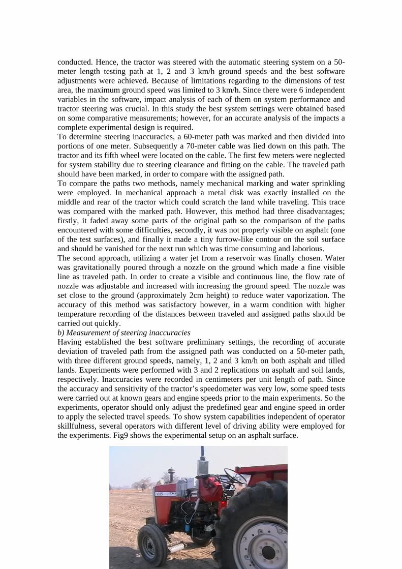
66
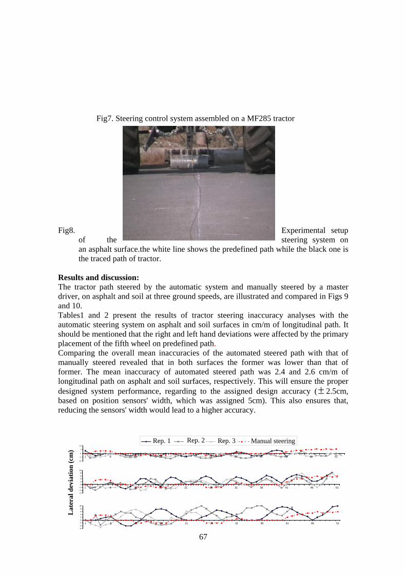
Fig7. Steering control system assembled on a MF285 tractor
Fig8. Experimental setup of the steering system on an asphalt surface.the white line shows the predefined path while the black one is the traced path of tractor.
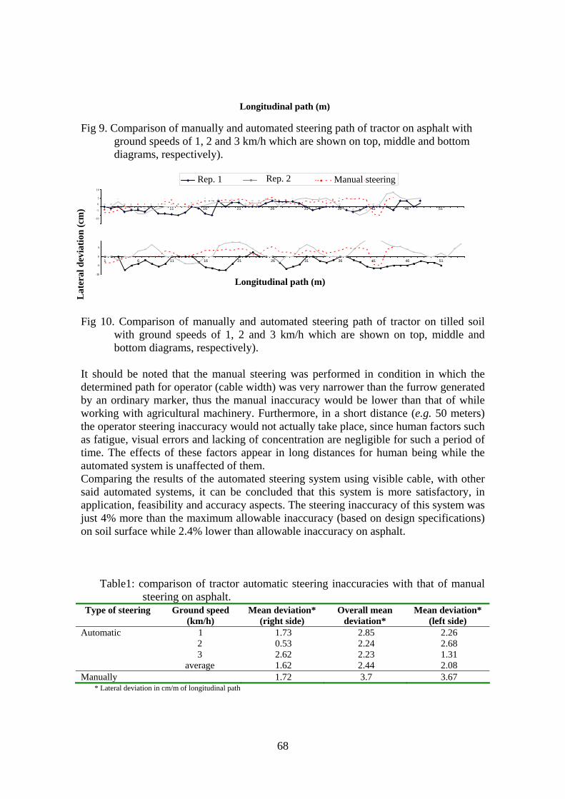
Results and discussion: The tractor path steered by the automatic system and manually steered by a master driver, on asphalt and soil at three ground speeds, are illustrated and compared in Figs 9 and 10. Tables1 and 2 present the results of tractor steering inaccuracy analyses with the automatic steering system on asphalt and soil surfaces in cm/m of longitudinal path. It should be mentioned that the right and left hand deviations were affected by the primary placement of the fifth wheel on predefined path. Comparing the overall mean inaccuracies of the automated steered path with that of manually steered revealed that in both surfaces the former was lower than that of former. The mean inaccuracy of automated steered path was 2.4 and 2.6 cm/m of longitudinal path on asphalt and soil surfaces, respectively. This will ensure the proper designed system performance, regarding to the assigned design accuracy ( 2.5cm, based on position sensors' width, which was assigned 5cm). This also ensures that, reducing the sensors' width would lead to a higher accuracy.
±
-6-4-202468
10
1 6 11 16 21 26 31 36 41 46 51
Lat
eral
dev
iatio
n (c
m)
-10
-5
0
5
10
1 6 11 16 21 26 31 36 41 46 51
Rep. 1 Rep. 2 Rep. 3 Manual steering
108
46
20
1 6 11 16 21 26 31 36 41 46 51-2-4-6
67
Longitudinal path (m)
Fig 9. Comparison of manually and automated steering path of tractor on asphalt with ground speeds of 1, 2 and 3 km/h which are shown on top, middle and bottom diagrams, respectively).
-10
-5
0
5
1 6 11 16 21 26 31 36 41 46 51
10
Fig 10. Comparison of manually and automated steering path of tractor on tilled soil
with ground speeds of 1, 2 and 3 km/h which are shown on top, middle and bottom diagrams, respectively).
It should be noted that the manual steering was performed in condition in which the determined path for operator (cable width) was very narrower than the furrow generated by an ordinary marker, thus the manual inaccuracy would be lower than that of while working with agricultural machinery. Furthermore, in a short distance (e.g. 50 meters) the operator steering inaccuracy would not actually take place, since human factors such as fatigue, visual errors and lacking of concentration are negligible for such a period of time. The effects of these factors appear in long distances for human being while the automated system is unaffected of them. Comparing the results of the automated steering system using visible cable, with other said automated systems, it can be concluded that this system is more satisfactory, in application, feasibility and accuracy aspects. The steering inaccuracy of this system was just 4% more than the maximum allowable inaccuracy (based on design specifications) on soil surface while 2.4% lower than allowable inaccuracy on asphalt.
Table1: comparison of tractor automatic steering inaccuracies with that of manual steering on asphalt.
Type of steering Ground speed (km/h)
Mean deviation* (right side)
Overall mean deviation*
Mean deviation* (left side)
1 1.73 2.85 2.26 2 0.53 2.24 2.68 3 2.62 2.23 1.31
Automatic
average 1.62 2.44 2.08 Manually 1.72 3.7 3.67 * Lateral deviation in cm/m of longitudinal path
-10
-5
0
5
1 6 11 16 21 26 31 36 41 46 51
Rep. 1 Rep. 2 Manual steering10
5
0
1 6 11 16 21 26 31 36 41 46 51
Lat
eral
dev
iatio
n (c
m) -5
-10
Longitudinal path (m)
68
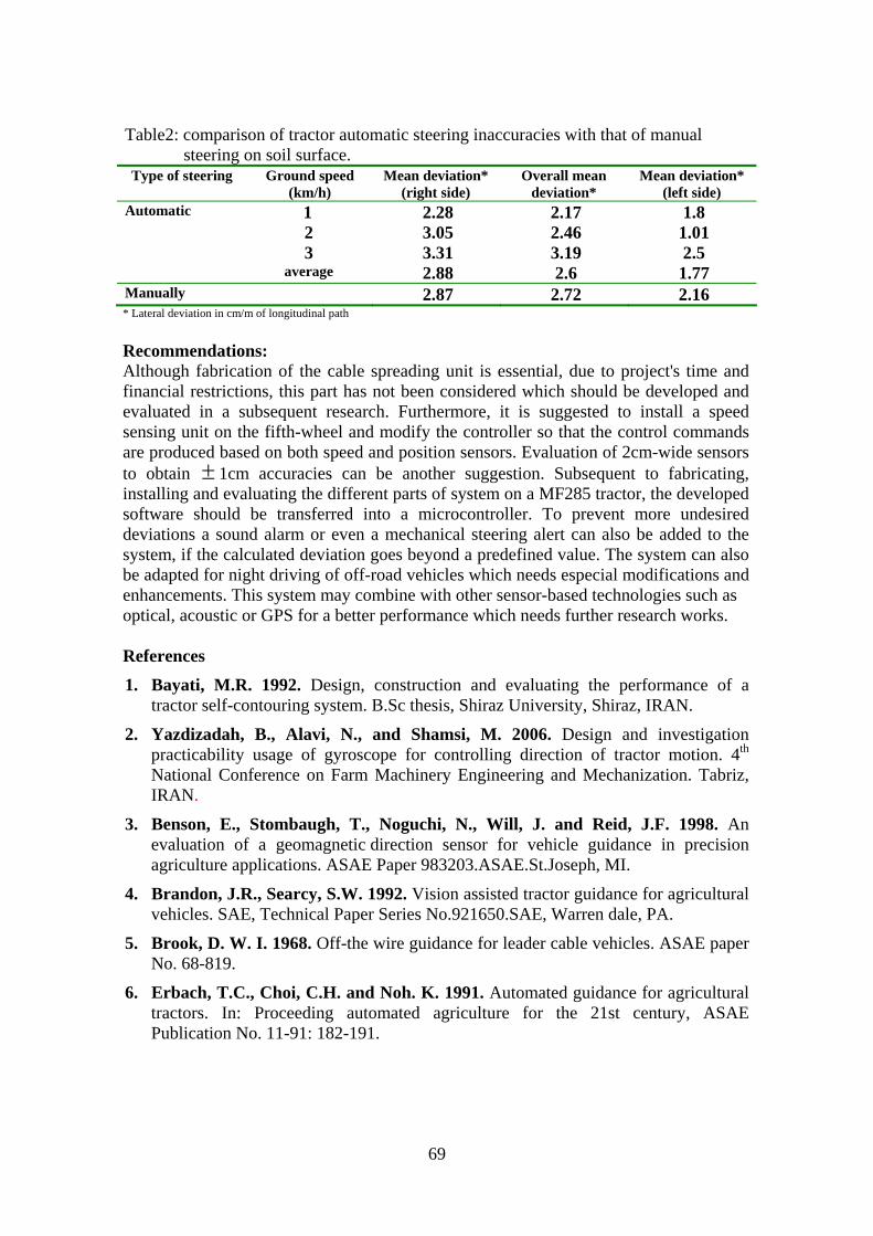
Table2: comparison of tractor automatic steering inaccuracies with that of manual steering on soil surface.
Type of steering Ground speed (km/h)
Mean deviation* (right side)
Overall mean deviation*
Mean deviation* (left side)
1 2.28 2.17 1.8 2 3.05 2.46 1.01 3 3.31 3.19 2.5
Automatic
average 2.88 2.6 1.77 Manually 2.87 2.72 2.16 * Lateral deviation in cm/m of longitudinal path Recommendations: Although fabrication of the cable spreading unit is essential, due to project's time and financial restrictions, this part has not been considered which should be developed and evaluated in a subsequent research. Furthermore, it is suggested to install a speed sensing unit on the fifth-wheel and modify the controller so that the control commands are produced based on both speed and position sensors. Evaluation of 2cm-wide sensors to obtain ± 1cm accuracies can be another suggestion. Subsequent to fabricating, installing and evaluating the different parts of system on a MF285 tractor, the developed software should be transferred into a microcontroller. To prevent more undesired deviations a sound alarm or even a mechanical steering alert can also be added to the system, if the calculated deviation goes beyond a predefined value. The system can also be adapted for night driving of off-road vehicles which needs especial modifications and enhancements. This system may combine with other sensor-based technologies such as optical, acoustic or GPS for a better performance which needs further research works. References 1. Bayati, M.R. 1992. Design, construction and evaluating the performance of a
tractor self-contouring system. B.Sc thesis, Shiraz University, Shiraz, IRAN.
2. Yazdizadah, B., Alavi, N., and Shamsi, M. 2006. Design and investigation practicability usage of gyroscope for controlling direction of tractor motion. 4th National Conference on Farm Machinery Engineering and Mechanization. Tabriz, IRAN.
3. Benson, E., Stombaugh, T., Noguchi, N., Will, J. and Reid, J.F. 1998. An evaluation of a geomagnetic direction sensor for vehicle guidance in precision agriculture applications. ASAE Paper 983203.ASAE.St.Joseph, MI.
4. Brandon, J.R., Searcy, S.W. 1992. Vision assisted tractor guidance for agricultural vehicles. SAE, Technical Paper Series No.921650.SAE, Warren dale, PA.
5. Brook, D. W. I. 1968. Off-the wire guidance for leader cable vehicles. ASAE paper No. 68-819.
6. Erbach, T.C., Choi, C.H. and Noh. K. 1991. Automated guidance for agricultural tractors. In: Proceeding automated agriculture for the 21st century, ASAE Publication No. 11-91: 182-191.
69

70
7. Reid, J. F., Zhang, Q., Noguchi, N. and Dickson, M. 2000.Agricultural automatic guidance research in North America. Computers and Electronics in Agriculture,25: 155–167
8. Fehr, B.W., Gerrish, J.B., 1995.Vision-guided row crop, follower. Apply. Eng. Agric. 11 (4), 613-620.
9. Kirk, T.G., 1974. A Furrow-Following Tractor Guidance System, M.Sc. Thesis, Department of Mechanical Engineering , University of Saskatchewan, Canada.
10. Noguchi, N., Reid, J.F., Benson, E., Will J. and Stombaugh. T., 1998. Vehicle automation system based on multi-sensor integration. ASAE Paper No. 983111.
11. Ollis, M. and Stentz, A. 1997.Vision-based perception for an automated harvester. IEEE International on Robotics and Intelligent Machines in Agriculture. ASAE, St.Joseph, MI.pp.30 –41.
12. Willrodt, F. L. 1924. Steering attachment for tractors. U. S. Patent No.150670