Automated Method Scouting - Thermo Fisher Scientific · PDF filecut the tubing with a sharp...
17
Automated Method Scouting Quick Installation Guide Thermo Scientific Dionex UltiMate 3000 LC, RSLC, Bio RS and Dual Gradient Systems P/N 4823.0205 Revision B December 2014
Transcript of Automated Method Scouting - Thermo Fisher Scientific · PDF filecut the tubing with a sharp...

Automated Method Scouting
Quick Installation Guide Thermo Scientific Dionex UltiMate 3000
LC, RSLC, Dual Gradient Systems and BioRS
P/N 4823.0205 Revision B December 2014
Automated Method Scouting
Quick Installation Guide Thermo Scientific Dionex UltiMate 3000
LC, RSLC, Bio RS and Dual Gradient Systems
P/N 4823.0205 Revision B December 2014
Quick Installation Guide Automated Method Scouting
T h e r m o F i s h e r S c i e n t i f i c P a g e | i
Considerations All information in this manual is subject to change without notice and does not represent a commitment on the part of Thermo Fisher Scientific. UltiMate™, Chromeleon™, Viper™, and nanoViper™ are trademarks of Thermo Fisher Scientific and its subsidiaries. Any other mentioned trade or company name(s) are subject to the copyright and the property and trademark rights of the respective companies. All rights reserved including those for photomechanical reproduction and storage on electronic media. Without the written permission of Thermo Fisher Scientific, no part of this publication may be reproduced in any form (by means of photocopy, microfilm, or any other process) for any purpose or processed, copied, transmitted, or distributed in any other form.
How to use this Manual These Quick Installation Guides describe how to assemble a dedicated Thermo Scientific Dionex UltiMate 3000 system with Thermo Scientific Dionex UHPLC+ Solution hardware. It is assumed that the individual using this manual has a sufficient training in the use of UltiMate™ 3000 systems, is aware of the potential hazards including (but not limited to) electrical hazards, chemical solvent hazards, exposure to UV radiation, and exposure to pressurized solvents. The layout of this manual is designed to provide quick reference to the sections of interest. However, a review of the whole manual is recommended to obtain a full understanding of the Dionex UHPLC+ Solution and to operate the modified instrument properly. This manual is provided as state-of-the-art. Every effort has been made to supply complete and accurate information. All technical specifications and programs have been developed with the utmost care. However, Thermo Fisher Scientific assumes no responsibility and cannot be held liable for any errors, omissions, damage or loss that might result from any use of this manual or the information contained therein. We appreciate your help in eliminating any errors that may appear in this document. The Tip and Note signs shown below are included in various locations in this manual and provide the following information:
Tip: Indicates general information intended to optimize the workflow or indicates additional information.
Note: Indicates specific information intended to run the UHPLC+ Solution properly.
All UHPLC+ Solution Kits are delivered (besides Viper™ capillaries and other equipment) with a printed Quick Installation Guide and a printed laminated Flow Scheme Card. The kit also contains an appropriate UHPLC+ Solution CD with digital versions of those manuals described above, Operating Instructions, and demo data.

Automated Method Scouting Quick Installation Guide
ii | P a g e T h e r m o F i s h e r S c i e n t i f i c
Table of Contents
Considerations ....................................................................................... i
How to use this Manual ......................................................................... i
Table of Contents .................................................................................. ii
1. Introduction ..................................................................................... 1
1.1 Viper UHPLC+ Solution Kits ......................................................................... 1
1.2 Typical System Setups ................................................................................. 2
1.2.1 Single-Stack .............................................................................................. 2
1.2.2 Dual-Stack ................................................................................................ 2
1.3 Connecting the Eluent Line to the Solvent Reservoir ................................... 3
1.4 Viper Capillaries ........................................................................................... 4
1.5 nanoViper Capillaries ................................................................................... 4
1.6 Viper Labeling .............................................................................................. 4
1.7 Tightening a Viper ........................................................................................ 5
1.8 Eluent Conditioner ........................................................................................ 5
2. Automated Method Scouting ......................................................... 6
2.1 Benefit of Automated Method Scouting ........................................................ 6
2.2 Scope of Delivery ......................................................................................... 6
2.3 Stacking the Modules ................................................................................... 8
2.4 Flow Schematics .......................................................................................... 8
3. Extension Kit for Automated Method Scouting .......................... 10
3.1 Benefit of the Extension Kit for Automated Method Scouting ..................... 10
3.2 Scope of Delivery ....................................................................................... 10
3.3 Stacking the Modules with Extension Kit .................................................... 12
3.4 Flow Schematics with Extension Kit ........................................................... 13
Quick Installation Guide Automated Method Scouting
T h e r m o F i s h e r S c i e n t i f i c P a g e | 1
1. Introduction Thermo Fisher Scientific has developed a number of Dionex UHPLC+ Solutions to obtain the following benefits:
Combining the advanced features of UHPLC+ focused UltiMate 3000 hardware, Chromeleon Chromatography Data System software, and Viper UHPLC+ Solutions Kits.
The best possible synergy of performance, reliability and ease-of-operation of UHPLC+ focused UltiMate 3000 system(s).
Solving typical analytical challenges, such as method development, sample preparation, or increasing throughput and productivity.
All Viper UHPLC+ Solution Kits are predominantly designed for use with column lengths of up to 250 mm and work for the given chromatographic scenario of Chapter 2, which provides the recommended schematic system setup(s).
1.1 Viper UHPLC+ Solution Kits
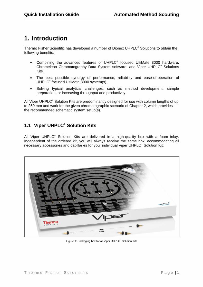
All Viper UHPLC+ Solution Kits are delivered in a high-quality box with a foam inlay. Independent of the ordered kit, you will always receive the same box, accommodating all necessary accessories and capillaries for your individual Viper UHPLC+ Solution Kit.
Figure 1: Packaging box for all Viper UHPLC
+ Solution Kits
Automated Method Scouting Quick Installation Guide
2 | P a g e T h e r m o F i s h e r S c i e n t i f i c
1.2 Typical System Setups
1.2.1 Single-Stack
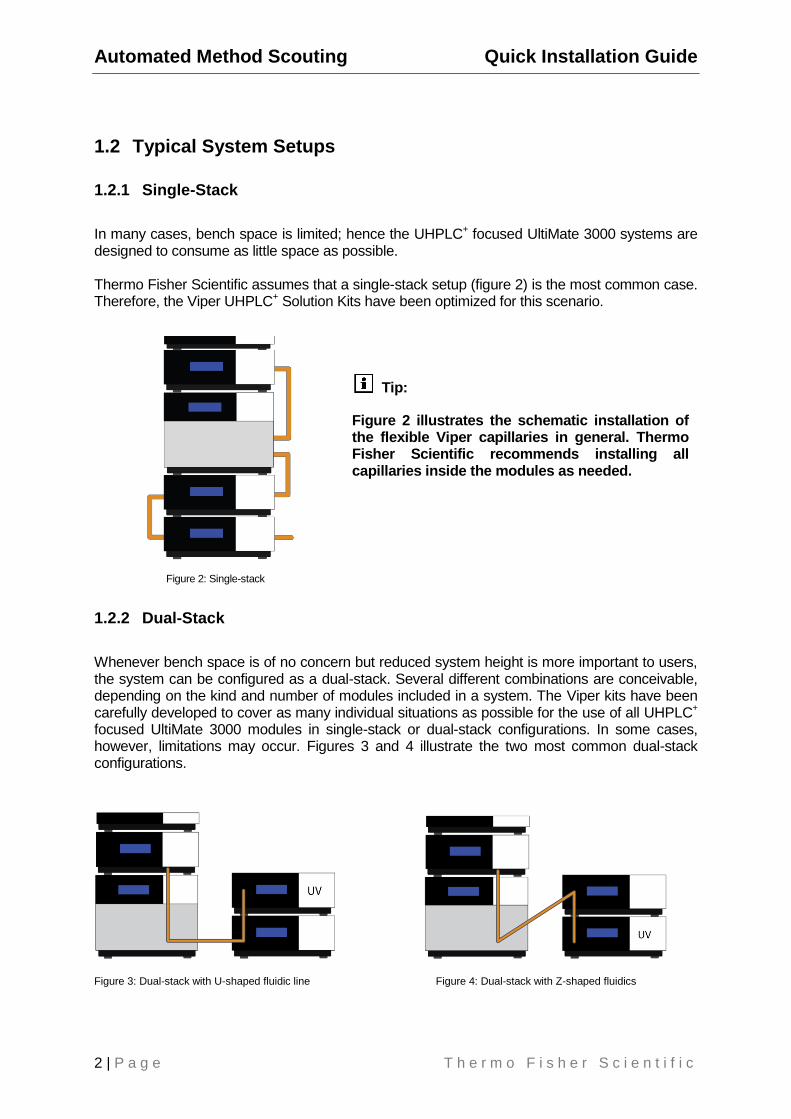
In many cases, bench space is limited; hence the UHPLC+ focused UltiMate 3000 systems are designed to consume as little space as possible. Thermo Fisher Scientific assumes that a single-stack setup (figure 2) is the most common case. Therefore, the Viper UHPLC+ Solution Kits have been optimized for this scenario.
Figure 2: Single-stack
1.2.2 Dual-Stack
Whenever bench space is of no concern but reduced system height is more important to users, the system can be configured as a dual-stack. Several different combinations are conceivable, depending on the kind and number of modules included in a system. The Viper kits have been carefully developed to cover as many individual situations as possible for the use of all UHPLC+ focused UltiMate 3000 modules in single-stack or dual-stack configurations. In some cases, however, limitations may occur. Figures 3 and 4 illustrate the two most common dual-stack configurations.
Figure 3: Dual-stack with U-shaped fluidic line Figure 4: Dual-stack with Z-shaped fluidics
Tip:
Figure 2 illustrates the schematic installation of the flexible Viper capillaries in general. Thermo Fisher Scientific recommends installing all capillaries inside the modules as needed.
Quick Installation Guide Automated Method Scouting
T h e r m o F i s h e r S c i e n t i f i c P a g e | 3
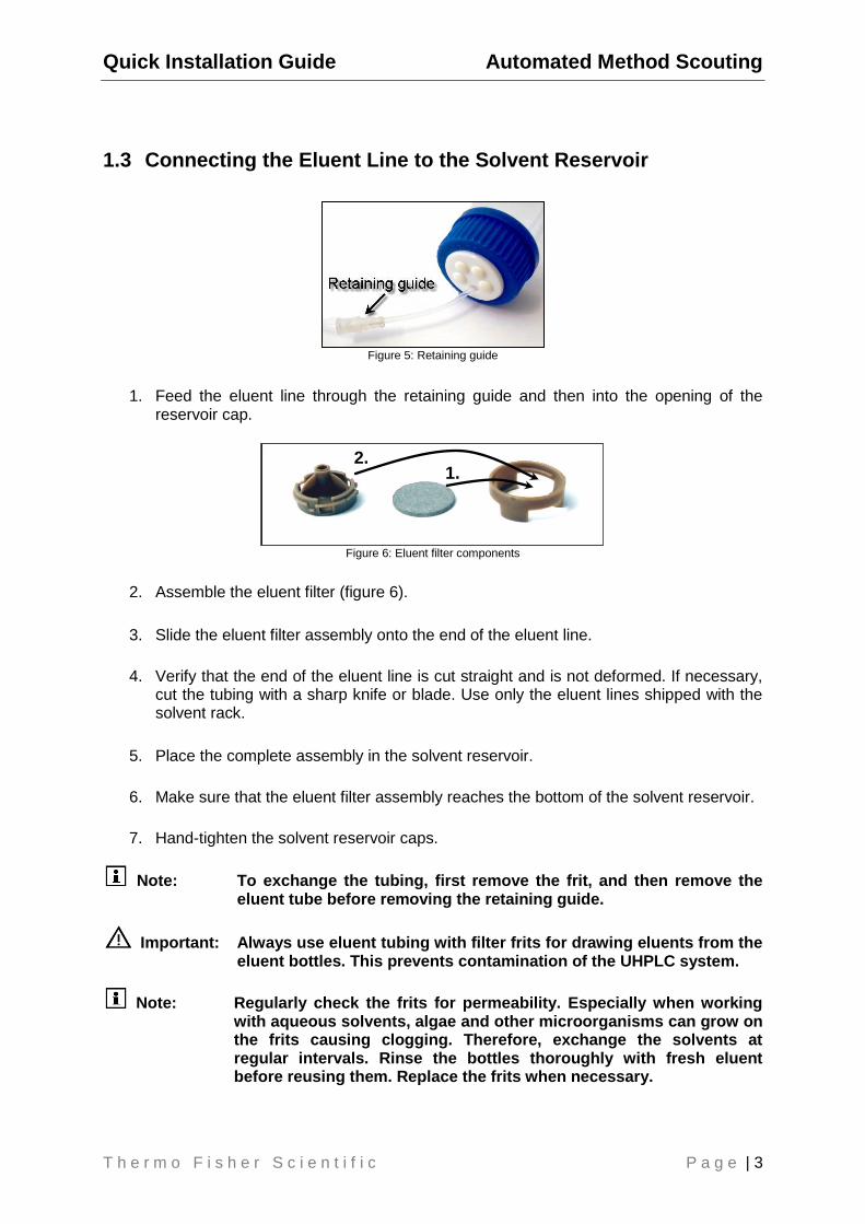
1.3 Connecting the Eluent Line to the Solvent Reservoir
Figure 5: Retaining guide
1. Feed the eluent line through the retaining guide and then into the opening of the reservoir cap.
Figure 6: Eluent filter components
2. Assemble the eluent filter (figure 6).
3. Slide the eluent filter assembly onto the end of the eluent line.
4. Verify that the end of the eluent line is cut straight and is not deformed. If necessary, cut the tubing with a sharp knife or blade. Use only the eluent lines shipped with the solvent rack.
5. Place the complete assembly in the solvent reservoir.
6. Make sure that the eluent filter assembly reaches the bottom of the solvent reservoir.
7. Hand-tighten the solvent reservoir caps.
Note: To exchange the tubing, first remove the frit, and then remove the eluent tube before removing the retaining guide.
Important: Always use eluent tubing with filter frits for drawing eluents from the eluent bottles. This prevents contamination of the UHPLC system.
Note: Regularly check the frits for permeability. Especially when working with aqueous solvents, algae and other microorganisms can grow on the frits causing clogging. Therefore, exchange the solvents at regular intervals. Rinse the bottles thoroughly with fresh eluent before reusing them. Replace the frits when necessary.
1. 2.
Automated Method Scouting Quick Installation Guide
4 | P a g e T h e r m o F i s h e r S c i e n t i f i c
1.4 Viper Capillaries
When working with small column volumes, capillaries and connections require special attention. But even with conventional columns and moderate pressures, mediocre connections can cause retention time shifts and peak distortions. Conventional stainless steel HPLC connectors use a ferrule and a nut to establish connections. A flaw of the conventional design is that a void volume-free connection is not guaranteed, particularly when changing the tubing between differently shaped threads (e.g., when changing a column). Viper connectors provide virtually zero dead volume by sealing at the tubing tip, hence ensuring optimized connections of conventional HPLC and modern UHPLC systems without any additional tools.
Even though Viper withstands UHPLC backpressures of up to 1,250 bar (17,400 psi) for stainless steel and 1,500 bar (22,000 psi) for MP35N™ capillaries, it is a finger-tight fitting system, which requires only small torques to seal, and is compatible with third-party valves and unions.
1.5 nanoViper Capillaries
When working with capillary and nano LC, a single bad capillary connection can cause the difference between quality results and a failed experiment. The typical low flow rates in these applications make them exceptionally sensitive to dead volumes. Even when the nut, ferrule, PEEK sleeve, and column have been connected dead-volume free, care must be taken to not over-tighten and damage the fused silica or, worse, the separation column. Remedying this, nanoViper is a finger-tight connection system for nano LC connections which eliminates the assembly of PEEK sleeve connections. It is preassembled to maximize ease-of-use. The nanoViper fitting is capable of withstanding pressures up to 1,034 bar (14,500 psi), and is compatible with third-party valves and unions.
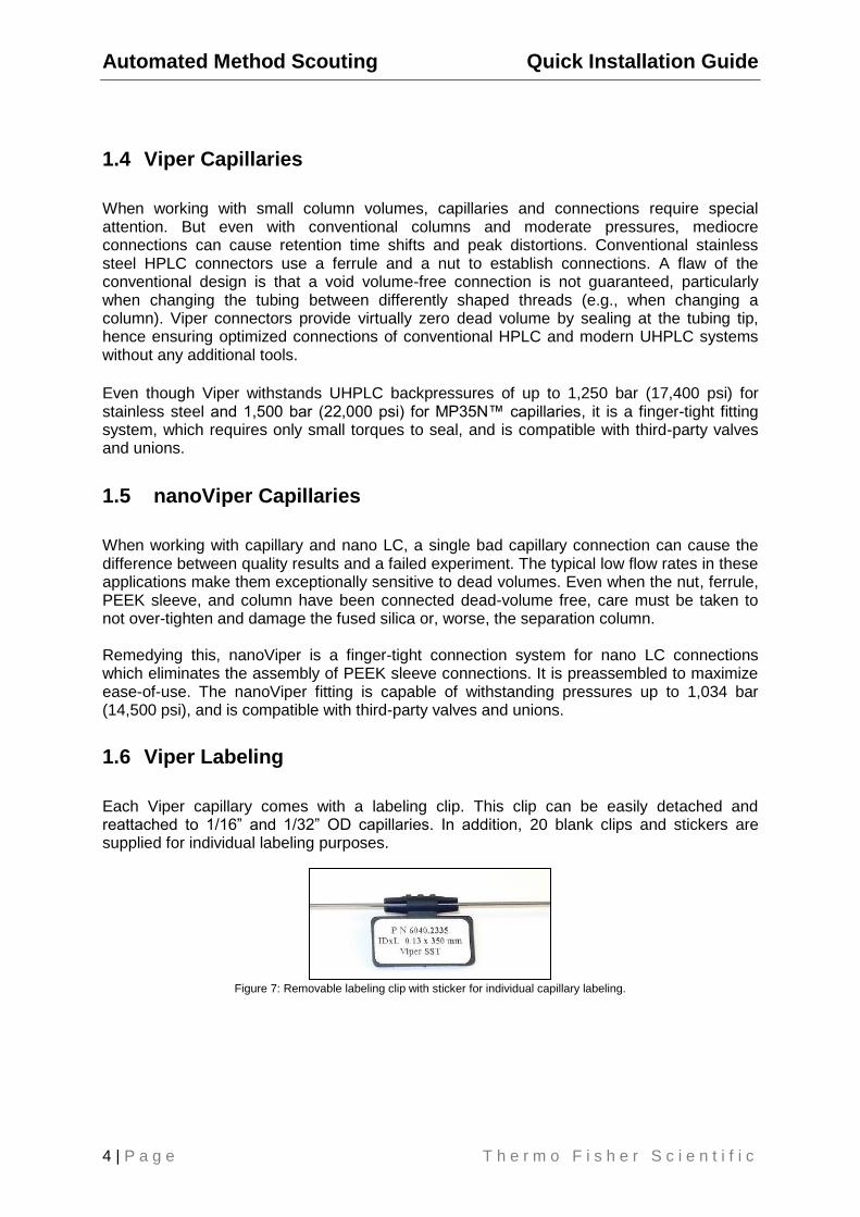
1.6 Viper Labeling
Each Viper capillary comes with a labeling clip. This clip can be easily detached and reattached to 1/16” and 1/32” OD capillaries. In addition, 20 blank clips and stickers are supplied for individual labeling purposes.
Figure 7: Removable labeling clip with sticker for individual capillary labeling.
Quick Installation Guide Automated Method Scouting
T h e r m o F i s h e r S c i e n t i f i c P a g e | 5
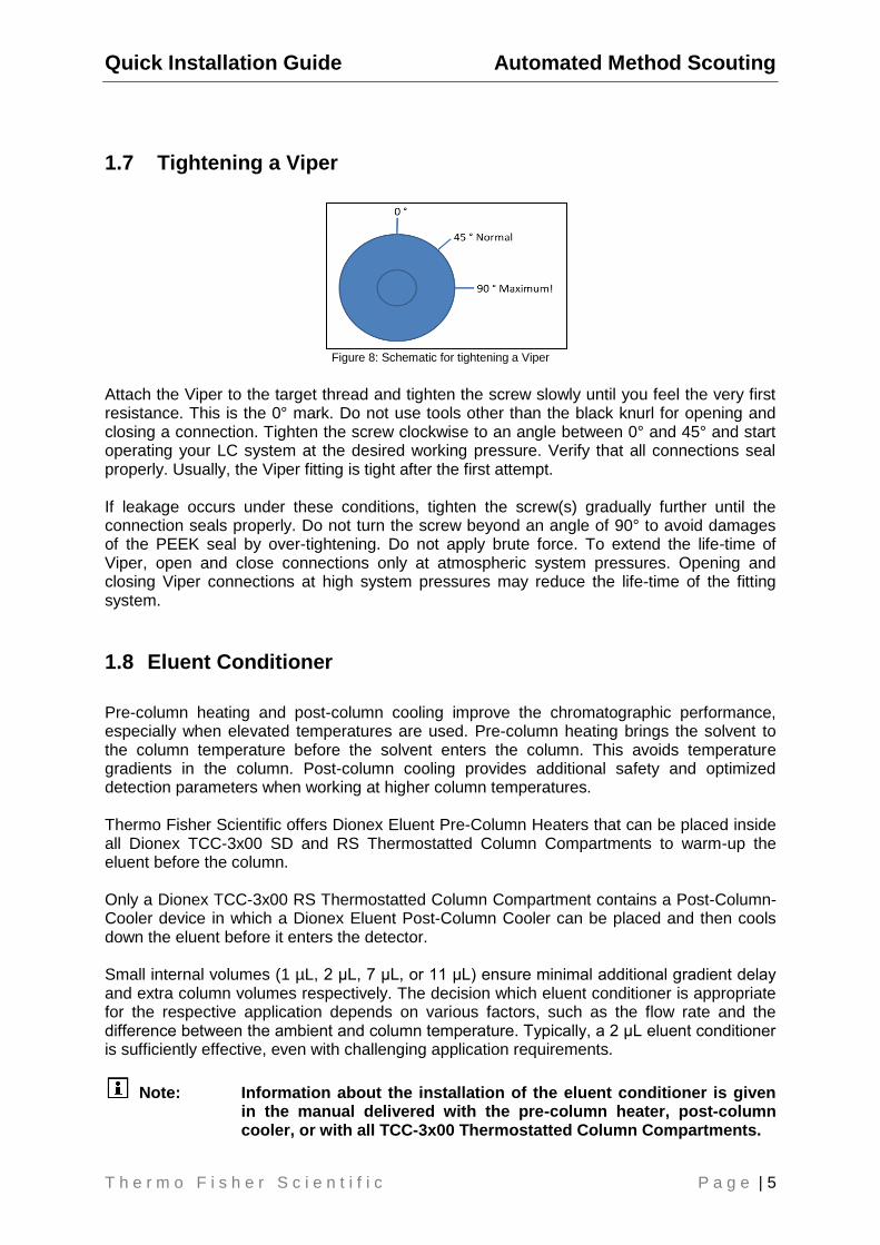
1.7 Tightening a Viper
Figure 8: Schematic for tightening a Viper
Attach the Viper to the target thread and tighten the screw slowly until you feel the very first resistance. This is the 0° mark. Do not use tools other than the black knurl for opening and closing a connection. Tighten the screw clockwise to an angle between 0° and 45° and start operating your LC system at the desired working pressure. Verify that all connections seal properly. Usually, the Viper fitting is tight after the first attempt. If leakage occurs under these conditions, tighten the screw(s) gradually further until the connection seals properly. Do not turn the screw beyond an angle of 90° to avoid damages of the PEEK seal by over-tightening. Do not apply brute force. To extend the life-time of Viper, open and close connections only at atmospheric system pressures. Opening and closing Viper connections at high system pressures may reduce the life-time of the fitting system.
1.8 Eluent Conditioner
Pre-column heating and post-column cooling improve the chromatographic performance, especially when elevated temperatures are used. Pre-column heating brings the solvent to the column temperature before the solvent enters the column. This avoids temperature gradients in the column. Post-column cooling provides additional safety and optimized detection parameters when working at higher column temperatures. Thermo Fisher Scientific offers Dionex Eluent Pre-Column Heaters that can be placed inside all Dionex TCC-3x00 SD and RS Thermostatted Column Compartments to warm-up the eluent before the column. Only a Dionex TCC-3x00 RS Thermostatted Column Compartment contains a Post-Column-Cooler device in which a Dionex Eluent Post-Column Cooler can be placed and then cools down the eluent before it enters the detector. Small internal volumes (1 µL, 2 μL, 7 μL, or 11 μL) ensure minimal additional gradient delay and extra column volumes respectively. The decision which eluent conditioner is appropriate for the respective application depends on various factors, such as the flow rate and the difference between the ambient and column temperature. Typically, a 2 μL eluent conditioner is sufficiently effective, even with challenging application requirements.
Note: Information about the installation of the eluent conditioner is given in the manual delivered with the pre-column heater, post-column cooler, or with all TCC-3x00 Thermostatted Column Compartments.

Automated Method Scouting Quick Installation Guide
6 | P a g e T h e r m o F i s h e r S c i e n t i f i c
2. Automated Method Scouting
Standard kit (SD) P/N 6040.2808 Rapid Separation kit (RS) P/N 6040.2807 Biocompatible Analytical kit P/N 6042.2808 Biocompatible Rapid Separation kit (BioRS) P/N 6042.2807
2.1 Benefit of Automated Method Scouting
Automated Method Scouting is a powerful UHPLC+ Solution for the convenient determination of the optimal combination of key method parameters, such as pH range, temperature range, stationary phase, and organic solvent type. Together with a thermostatted column compartment and two column selection valves, up to six different columns can be automatically scouted. All capillaries can be color-coded for easy identification of columns and related flow paths (capillary clips are scope of delivery). Chromeleon software provides comprehensive mining tools for data evaluation; smart reports visualize all results clearly and instantaneously. The UHPLC+ Solution ‘Automated Method Scouting’ includes a quaternary gradient pump, a thermostatted column compartment with two 6-position 7-port switching valves for column switching, a split loop well-plate autosampler, and preferably a diode array detector, all of which are fully controlled by the Chromeleon Chromatography Data System.
2.2 Scope of Delivery Table 1: Scope of delivery for the Viper Automated Method Scouting kits, RS kit (P/N 6040.2807) or SD kit (P/N 6040.2808)
Description Quantity
Viper capillary (SST), ID x L 0.13 mm/0.005” (only present in RS kits) 1 pcs.
Viper capillary (SST), ID x L 0.13 mm/0.005”or L 0.18 mm/0.007” x 250 mm 6 pcs.
Viper capillary (SST), ID x L 0.13 mm/0.005”or L 0.18 mm/0.007” x 350 mm 7 pcs.
Viper capillary (SST), ID x L 0.13 mm/0.005”or L 0.18 mm/0.007” x 450 mm 1 pc.
Viper capillary (SST), ID x L 0.18 mm/0.007” x 450 mm 1 pc.
Viper union for direct connection of two Viper capillaries 7 pcs.
Capillary marker 20 pcs.
Labels for capillary marker 20 pcs.
Capillary clip for color-coding, yellow 30 pcs.
Capillary clip for color-coding, white 30 pcs.
Capillary clip for color-coding, red 30 pcs.
Capillary clip for color-coding, black 30 pcs.
Capillary clip for color-coding, blue 30 pcs.
Capillary clip for color-coding, green 30 pcs.
Laminated flow scheme 1 pc.
Quick installation guide 1 pc.
UHPLC+ Solution CD for Automated Method Scouting 1 pc.

Quick Installation Guide Automated Method Scouting
T h e r m o F i s h e r S c i e n t i f i c P a g e | 7
Note: Automated Method Scouting Kit, SD system: All Viper Capillaries are delivered with an ID of 0.18 mm/0.007”.
Table 2: Scope of delivery for the biocompatible Viper Automated Method Scouting kits, BioRS kit (P/N 6042.2807) or the biocompatible analytical kit (P/N 6042.2808)
Description Quantity
Viper capillary (MP35N™), ID x L 0.10 mm/0.004”or L 0.18 mm/0.007” x 250 mm
6 pcs.
Viper capillary (MP35N™), ID x L 0.10 mm/0.004”or L 0.18 mm/0.007” x 350 mm
7 pcs.
Viper capillary (MP35N™), ID x L 0.10 mm/0.004”or L 0.18 mm/0.007” x 450 mm
1 pc.
Viper capillary (MP35N™), ID x L 0.18 mm/0.007” x 450 mm 1 pc.
Filter holder 4 pcs
Titanium suction filter 4 pcs
PEEK union, (pressure rating: 5,000 psi/344 bar) 7 pcs.
Capillary marker 20 pcs.
Labels for capillary marker 20 pcs.
Capillary clip for color-coding, yellow 30 pcs.
Capillary clip for color-coding, white 30 pcs.
Capillary clip for color-coding, red 30 pcs.
Capillary clip for color-coding, black 30 pcs.
Capillary clip for color-coding, blue 30 pcs.
Capillary clip for color-coding, green 30 pcs.
Laminated flow scheme 1 pc.
Quick installation guide 1 pc.
UHPLC+ Solution CD for Automated Method Scouting 1 pc.
Note: In the biocompatible analytical Automated Method Scouting Kit, all Viper capillaries are delivered with an ID of 0.18 mm/0.007”. Please make sure that no stainless steel eluent filters (part of the solvent rack) are used with any UltiMate 3000 BioRS system.
Automated Method Scouting Quick Installation Guide
8 | P a g e T h e r m o F i s h e r S c i e n t i f i c
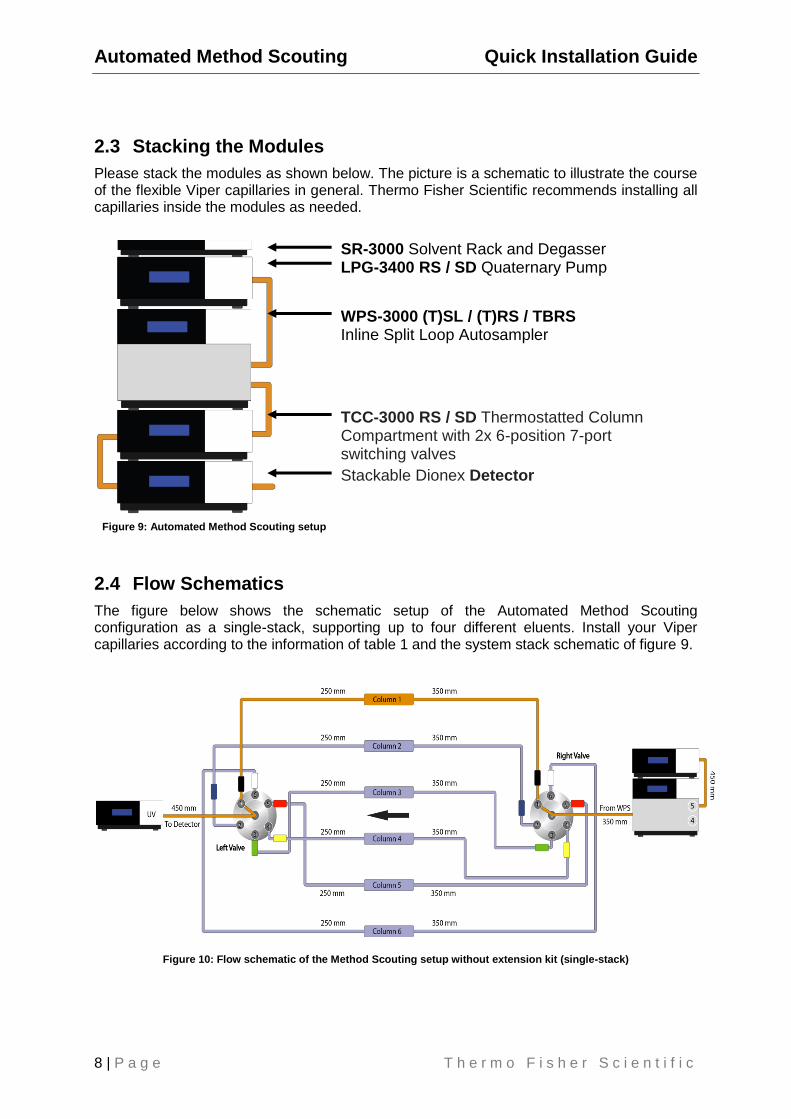
2.3 Stacking the Modules
Please stack the modules as shown below. The picture is a schematic to illustrate the course of the flexible Viper capillaries in general. Thermo Fisher Scientific recommends installing all capillaries inside the modules as needed.
SR-3000 Solvent Rack and Degasser LPG-3400 RS / SD Quaternary Pump
WPS-3000 (T)SL / (T)RS / TBRS Inline Split Loop Autosampler
TCC-3000 RS / SD Thermostatted Column Compartment with 2x 6-position 7-port switching valves
Stackable Dionex Detector
2.4 Flow Schematics
The figure below shows the schematic setup of the Automated Method Scouting configuration as a single-stack, supporting up to four different eluents. Install your Viper capillaries according to the information of table 1 and the system stack schematic of figure 9.
Figure 10: Flow schematic of the Method Scouting setup without extension kit (single-stack)
Figure 9: Automated Method Scouting setup
Quick Installation Guide Automated Method Scouting
T h e r m o F i s h e r S c i e n t i f i c P a g e | 9
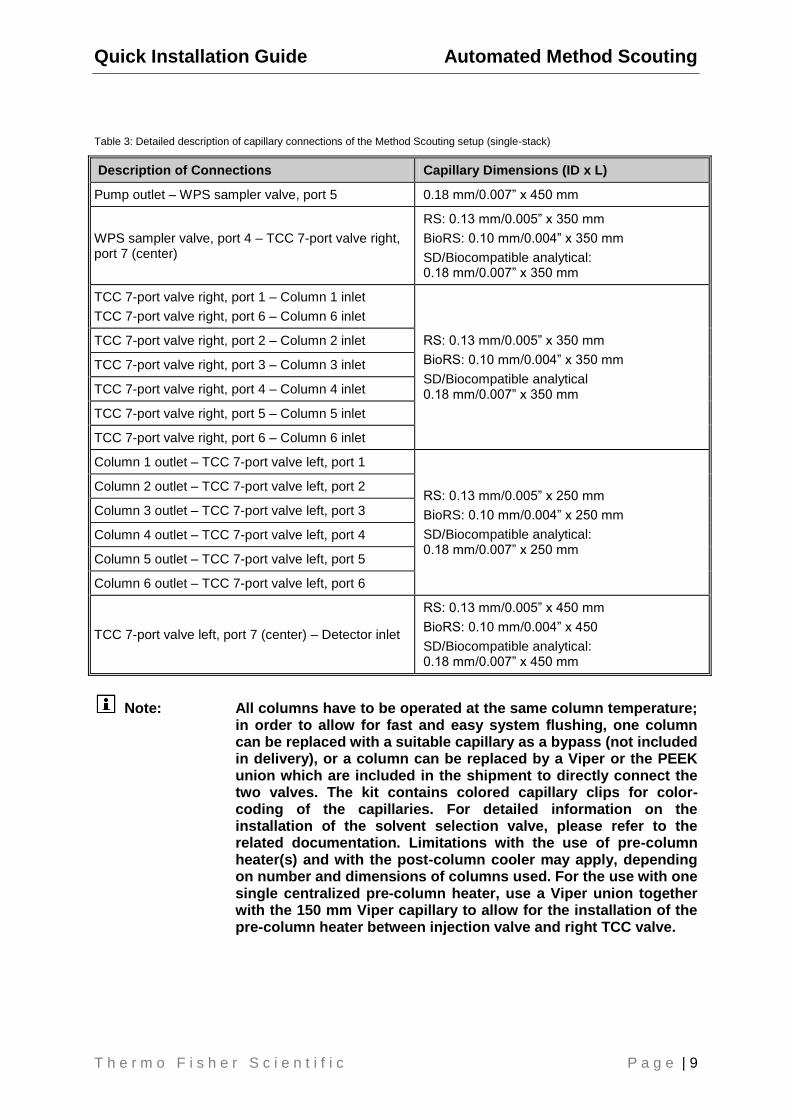
Table 3: Detailed description of capillary connections of the Method Scouting setup (single-stack)
Description of Connections Capillary Dimensions (ID x L)
Pump outlet – WPS sampler valve, port 5 0.18 mm/0.007” x 450 mm
WPS sampler valve, port 4 – TCC 7-port valve right, port 7 (center)
RS: 0.13 mm/0.005” x 350 mm
BioRS: 0.10 mm/0.004” x 350 mm
SD/Biocompatible analytical: 0.18 mm/0.007” x 350 mm
TCC 7-port valve right, port 1 – Column 1 inlet
TCC 7-port valve right, port 6 – Column 6 inlet
RS: 0.13 mm/0.005” x 350 mm
BioRS: 0.10 mm/0.004” x 350 mm
SD/Biocompatible analytical 0.18 mm/0.007” x 350 mm
TCC 7-port valve right, port 2 – Column 2 inlet
TCC 7-port valve right, port 3 – Column 3 inlet
TCC 7-port valve right, port 4 – Column 4 inlet
TCC 7-port valve right, port 5 – Column 5 inlet
TCC 7-port valve right, port 6 – Column 6 inlet
Column 1 outlet – TCC 7-port valve left, port 1
RS: 0.13 mm/0.005” x 250 mm
BioRS: 0.10 mm/0.004” x 250 mm
SD/Biocompatible analytical: 0.18 mm/0.007” x 250 mm
Column 2 outlet – TCC 7-port valve left, port 2
Column 3 outlet – TCC 7-port valve left, port 3
Column 4 outlet – TCC 7-port valve left, port 4
Column 5 outlet – TCC 7-port valve left, port 5
Column 6 outlet – TCC 7-port valve left, port 6
TCC 7-port valve left, port 7 (center) – Detector inlet
RS: 0.13 mm/0.005” x 450 mm
BioRS: 0.10 mm/0.004” x 450
SD/Biocompatible analytical: 0.18 mm/0.007” x 450 mm
Note: All columns have to be operated at the same column temperature; in order to allow for fast and easy system flushing, one column can be replaced with a suitable capillary as a bypass (not included in delivery), or a column can be replaced by a Viper or the PEEK union which are included in the shipment to directly connect the two valves. The kit contains colored capillary clips for color-coding of the capillaries. For detailed information on the installation of the solvent selection valve, please refer to the related documentation. Limitations with the use of pre-column heater(s) and with the post-column cooler may apply, depending on number and dimensions of columns used. For the use with one single centralized pre-column heater, use a Viper union together with the 150 mm Viper capillary to allow for the installation of the pre-column heater between injection valve and right TCC valve.

Automated Method Scouting Quick Installation Guide
10 | P a g e T h e r m o F i s h e r S c i e n t i f i c
3. Extension Kit for Automated Method Scouting Standard (SD) and Rapid Separation (RS) P/N 6040.0100 Biocompatible analytical and Biocompatible RS (BioRS) P/N 6042.0100
3.1 Benefit of the Extension Kit for Automated Method Scouting
A special feature of the Automated Method Scouting configuration is the optional Extension Kit for Automated Method Scouting which allows for the use of up to 9 additional different mobile phases. The recommended setup without extension kit is the single stack, whereas the extension kit requires the dual-stack setup.
3.2 Scope of Delivery
Table 4: Scope of delivery of the Extension Kit for Automated Method Scouting, SD and RS System (P/N 6040.0100)
Description Quantity
SR-3000, Solvent Rack without degasser 1 pc.
Solvent selection valve, 10-pos 11-port 1 pc.
Mounting plate for solvent selection valve 1 pc.
Viper capillary (SST), ID x L 0.13 mm/0.005” x 650 mm 1 pc.
Viper capillary (SST), ID x L 0.18 mm/0.007” x 650 mm 1 pc.
Viper capillary (SST), ID x L 0.13 mm/0.005” x 150 mm 1 pc.
Viper capillary (SST), ID x L 0.18 mm/0.007” x 150 mm 1 pc.
Viper union for direct connection of two Viper capillaries 2 pcs.
Eluent bottle, 1 L 6 pcs.
Eluent filter for additional solvent bottles 10 pcs.
Retaining guide for solvent tubing 10 pcs.
Sealing plug for eluent bottle screw cap 40 pcs.
Eluent tubing, 1 m, for connecting 10 eluent bottles to the 10-pos 11-port valve 10 pcs.
Eluent tubing, 0.6 m, for connecting the 10-pos 11-port valve to the LPG-3400RS/SD pump
1 pc.
Laminated flow scheme 1 pc.
Quick installation guide 1 pc.
UHPLC+ Solution CD for Automated Method Scouting 1 pc.
Quick Installation Guide Automated Method Scouting
T h e r m o F i s h e r S c i e n t i f i c P a g e | 11
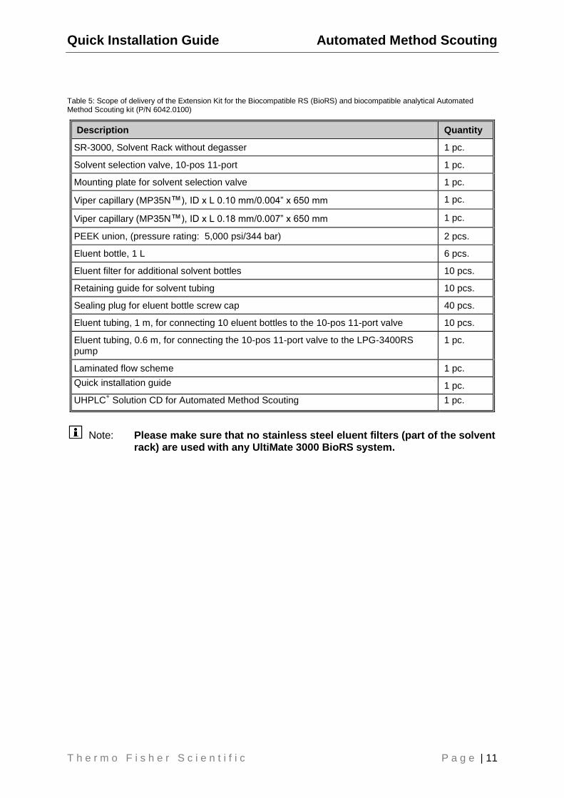
Table 5: Scope of delivery of the Extension Kit for the Biocompatible RS (BioRS) and biocompatible analytical Automated Method Scouting kit (P/N 6042.0100)
Description Quantity
SR-3000, Solvent Rack without degasser 1 pc.
Solvent selection valve, 10-pos 11-port 1 pc.
Mounting plate for solvent selection valve 1 pc.
Viper capillary (MP35N™), ID x L 0.10 mm/0.004” x 650 mm 1 pc.
Viper capillary (MP35N™), ID x L 0.18 mm/0.007” x 650 mm 1 pc.
PEEK union, (pressure rating: 5,000 psi/344 bar) 2 pcs.
Eluent bottle, 1 L 6 pcs.
Eluent filter for additional solvent bottles 10 pcs.
Retaining guide for solvent tubing 10 pcs.
Sealing plug for eluent bottle screw cap 40 pcs.
Eluent tubing, 1 m, for connecting 10 eluent bottles to the 10-pos 11-port valve 10 pcs.
Eluent tubing, 0.6 m, for connecting the 10-pos 11-port valve to the LPG-3400RS pump
1 pc.
Laminated flow scheme 1 pc.
Quick installation guide 1 pc.
UHPLC+ Solution CD for Automated Method Scouting 1 pc.
Note: Please make sure that no stainless steel eluent filters (part of the solvent rack) are used with any UltiMate 3000 BioRS system.

Automated Method Scouting Quick Installation Guide
12 | P a g e T h e r m o F i s h e r S c i e n t i f i c
3.3 Stacking the Modules with Extension Kit
Please stack the modules as shown below. The picture is a schematic to illustrate the course of the flexible Viper capillaries in general. Thermo Fisher Scientific recommends installing all capillaries inside the modules as needed. For the use of the Method Scouting Extension Kit, a dual-stack is recommended. In combination with the second solvent rack, this setup offers space for up to 9 additional solvent bottles and the solvent selection valve to be placed on top of the system.
Solvent Selection Valve with mounting plate SR-3000 Solvent Rack DAD-3000 (RS) Diode Array Detector (recommended) TCC-3000 RS / SD Thermostatted Column Compart-ment with 2x 6-pos 7-port switching valves
SR-3000 Solvent Rack
LPG-3400 RS / SD Quaternary Pump WPS-3000 (T)SL /(T)RS /TBRS inline Split Loop Autosampler
Note: All columns have to be operated at the same column temperature; in order to allow for fast and easy system flushing, one column can be replaced with a suitable capillary as a bypass (not included in delivery), or a column can be replaced by a Viper union or PEEK union which are included in the shipment to directly connect the two valves. The delivery contains colored capillary clips for color-coding of the capillaries. For detailed information on the installation of the solvent selection valve, please refer to the related documentation.
Figure 11: Dual-stack extension setup
Note: The recommended distance between the two stacks is approximately 10 cm (3.9 inches).
Quick Installation Guide Automated Method Scouting
T h e r m o F i s h e r S c i e n t i f i c P a g e | 13
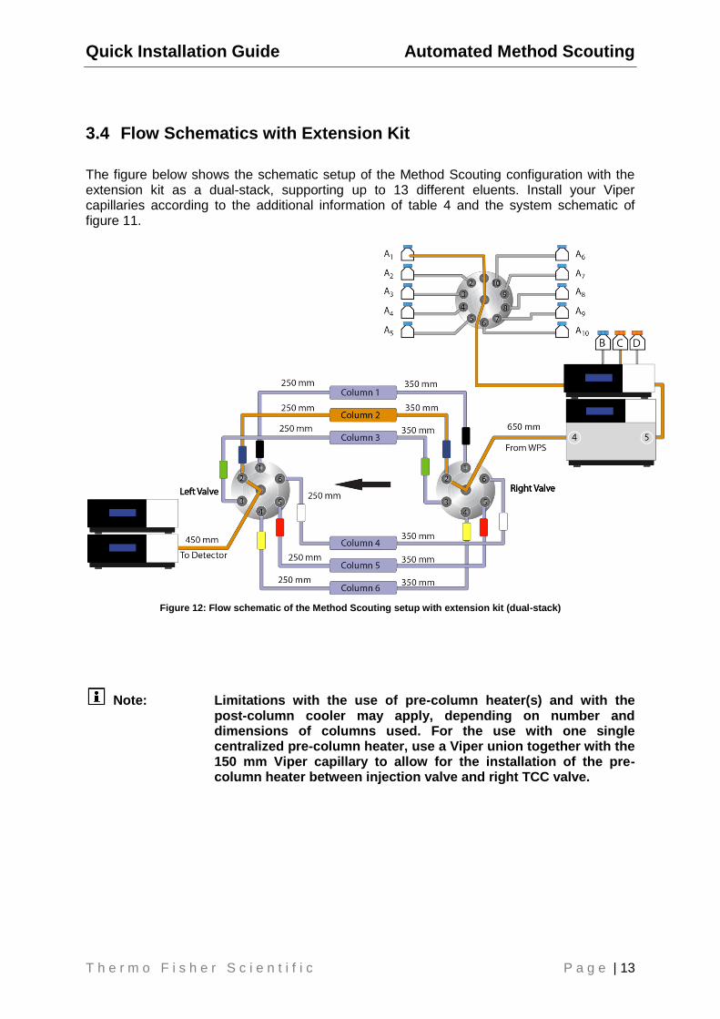
3.4 Flow Schematics with Extension Kit
The figure below shows the schematic setup of the Method Scouting configuration with the extension kit as a dual-stack, supporting up to 13 different eluents. Install your Viper capillaries according to the additional information of table 4 and the system schematic of figure 11.
Figure 12: Flow schematic of the Method Scouting setup with extension kit (dual-stack)
Note: Limitations with the use of pre-column heater(s) and with the post-column cooler may apply, depending on number and dimensions of columns used. For the use with one single centralized pre-column heater, use a Viper union together with the 150 mm Viper capillary to allow for the installation of the pre-column heater between injection valve and right TCC valve.
Automated Method Scouting Quick Installation Guide
14 | P a g e T h e r m o F i s h e r S c i e n t i f i c
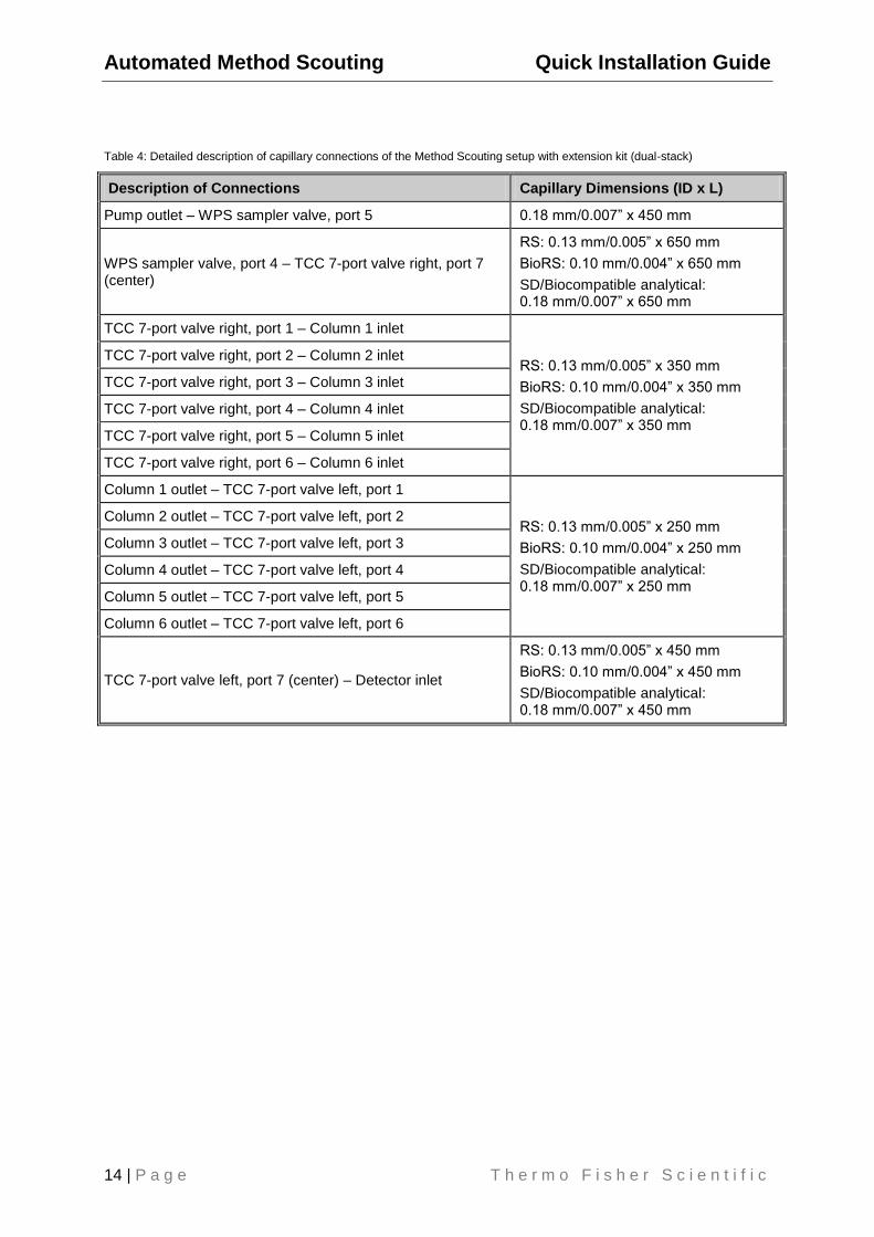
Table 4: Detailed description of capillary connections of the Method Scouting setup with extension kit (dual-stack)
Description of Connections Capillary Dimensions (ID x L)
Pump outlet – WPS sampler valve, port 5 0.18 mm/0.007” x 450 mm
WPS sampler valve, port 4 – TCC 7-port valve right, port 7 (center)
RS: 0.13 mm/0.005” x 650 mm
BioRS: 0.10 mm/0.004” x 650 mm
SD/Biocompatible analytical: 0.18 mm/0.007” x 650 mm
TCC 7-port valve right, port 1 – Column 1 inlet
RS: 0.13 mm/0.005” x 350 mm
BioRS: 0.10 mm/0.004” x 350 mm
SD/Biocompatible analytical: 0.18 mm/0.007” x 350 mm
TCC 7-port valve right, port 2 – Column 2 inlet
TCC 7-port valve right, port 3 – Column 3 inlet
TCC 7-port valve right, port 4 – Column 4 inlet
TCC 7-port valve right, port 5 – Column 5 inlet
TCC 7-port valve right, port 6 – Column 6 inlet
Column 1 outlet – TCC 7-port valve left, port 1
RS: 0.13 mm/0.005” x 250 mm
BioRS: 0.10 mm/0.004” x 250 mm
SD/Biocompatible analytical: 0.18 mm/0.007” x 250 mm
Column 2 outlet – TCC 7-port valve left, port 2
Column 3 outlet – TCC 7-port valve left, port 3
Column 4 outlet – TCC 7-port valve left, port 4
Column 5 outlet – TCC 7-port valve left, port 5
Column 6 outlet – TCC 7-port valve left, port 6
TCC 7-port valve left, port 7 (center) – Detector inlet
RS: 0.13 mm/0.005” x 450 mm
BioRS: 0.10 mm/0.004” x 450 mm
SD/Biocompatible analytical: 0.18 mm/0.007” x 450 mm