Optimising irrigation requirements of boro rice through timely sowing and short-duration varieties

Automated Irrigation System
Team Leader MARYAM AL KAABI
Team Leader DR.ALI ALHUMAIRI

Contents Section 1: Refined Project Description ........................................................................................................ 2
1.1. The problem addressed specifically in this project .............................................................................. 2
1.2. Project scope and expected outcome .................................................................................................. 2
Section 2: Refined Project Plan ................................................................................................................ 3
2.1. Detailed schedule and milestones ........................................................................................................ 3
2.2. Team structure and detailed roles/responsibilities of each membe ............................... 4
2.3. Contingency and risk mitigation plan ................................................................................................... 5
Section 3: System Requirements ......................................................................................................... 5
a) Requirement process ............................................................................................................................... 5
Easy to implement ................................................................................................................................ 6
Open source ......................................................................................................................................... 6
Strength ................................................................................................................................................ 6
Quality .................................................................................................................................................. 6
Modifiability ........................................................................................................................................ 6
b) List and categorization of system stakeholders, users, and clients. ...................................................... 7
3.2. System Requirements List:.................................................................................................................... 7
a) Functional requirements .......................................................................................................................... 7
b) Non-functional requirements .................................................................................................................. 8
Section 4: System Design ............................................................................................................................. 8
4.1. High level system architecture, data flows. ......................................................................................... 8
4.1. User interface ...................................................................................................................................... 12
Section 5: System Implementation ............................................................................................................ 13
5.1. Hardware and Software platforms ..................................................................................................... 13
Hardware platforms: .................................................................................................................................. 13
Software platforms: ................................................................................................................................... 14
5.2. Hardware and Software tools ............................................................................................................. 15
Section 6: Challenges.................................................................................................................................. 17
References .................................................................................................................................................. 19

Section 1: Refined Project Description
1.1. The problem addressed specifically in this project The economy of many countries depends on agriculture. To achieve the best quality, it is
important to focus on some characteristics such as the appropriate amount water
supply and a suitable schedule for irrigation of crops should be taken into consideration.
Farmers around the world face problems in meeting these standards, especially those
living in poverty. And with continued lack of efforts and delaying irrigation cause their
crops cannot grow, so it leads to problems. This is because of a lack of knowledge
economic of methods and technologies. There are different methods of irrigation such
as drip irrigation, sprinkler and others but still there is problems such as when there is
broken the water will leak out . The agricultural sector has great importance so it is
necessary to solve all these problems by developing an intelligent irrigation system.
1.2. Project scope and expected outcome The main objective of this project is to develop an intelligent system that solves most
problems related to irrigation and agriculture such as controlling and saving both the
water and electricity, Increasing agricultural production using small quantities of water ,
Minimize manual intervention in watering operations with increasing watering speed,
Preserving plants from fungi, and finally, easy to use. All these features make these
methods sustainable option to be considered to improve the agriculture and irrigation
efficiency.
After the implementation of this project it is expected to achieve several goals:
Reduce the water consumption.
Facilitate and simplify the irrigation system by installing and designing the whole
automatic irrigation system.
Increase agricultural production through timely irrigation according to the need
of the plant.
It can prevent irrigation happening on the day at the wrong time, to switch
engine ON or OFF by utilizing the irrigation system, the controller will work to
switch the engine, so no need for employers.
To reduce mistakes of operation due to employees as much as possible and to
preserve water from waste.

This prototype will be designed to operate for solving the problems of irrigation such as errors
caused by farmers and the consumption of massive quantities of water. These errors affect trees as
their fungi cause also affect the overall stock of water. Furthermore, it will operate to rise the
economic return of countries due to decrease the number of employees in field of agricultures.
Section 2: Refined Project Plan
2.1. Detailed schedule and milestones Milestones:
1. First of all we have discussed the main idea of the project, we had several meeting
and each member discussed her/his idea.
2. Second we made list of materials needed for this project.
3. After agreeing on the idea and method of action we divided the team into two group
searching. One group responsible for searching about related works and other group
responsible for materials searching and where can we find it etc.
4. Several Meeting have arranged to draw project sketch and make assumptions of
measurements and connections.
5. Then we decided to make small version of the project until we make order for all
materials needed.
6. Later we start working on hardware part and make all wires connection for each
device.
7. Later on we started on programming part where we programmed and test all sensors
individuals.
8. Then we combined all programming code together for the large scale project.
9. We make test for the entire project to make sure everything working as we want
using different condition for each sensors.
10. Then we divided the team into two groups, one for writing report and other one for
working and searching for software part which is mobile application and programming.

11. After that we meet all together to discuss what is needed to design mobile
application to control this project and the aim of this mobile application.
12. We spent some time searching for different tutorials for mobile application and
what is suitable for this project.
2.2. Team structure and detailed roles/responsibilities of each member
Team member color Maryam
Budoor
All
Figure 1: Timeline
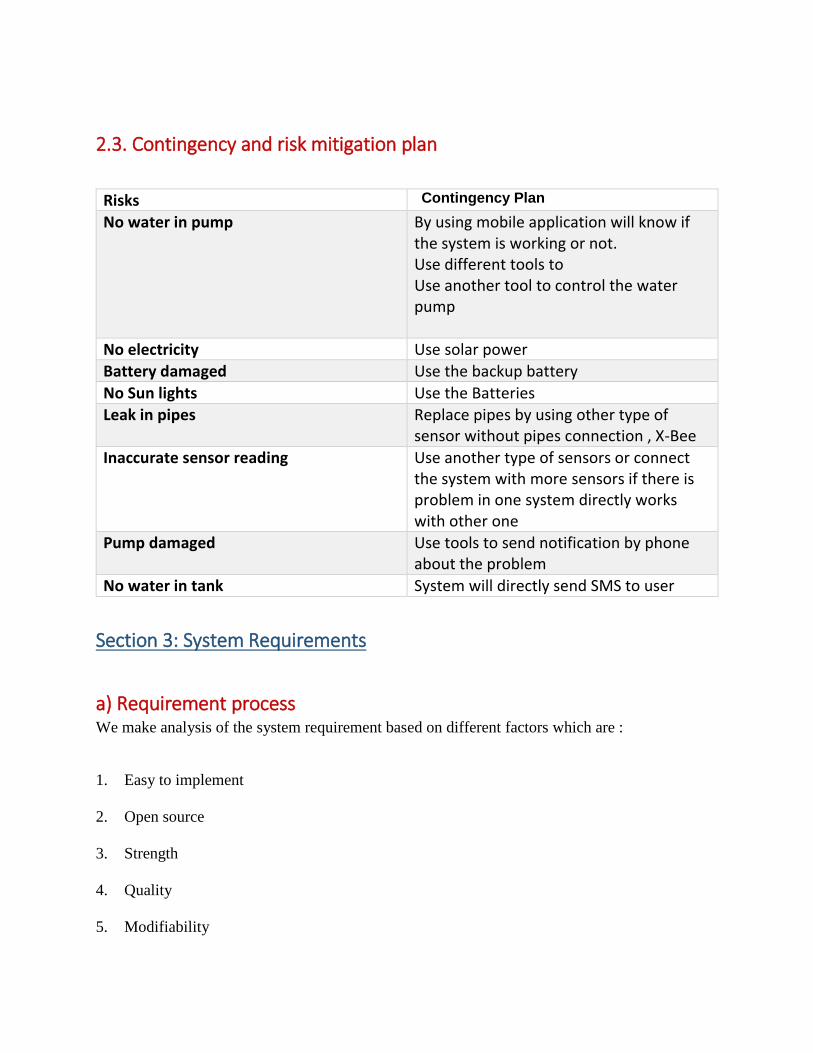
2.3. Contingency and risk mitigation plan
Risks Contingency Plan
No water in pump By using mobile application will know if the system is working or not. Use different tools to Use another tool to control the water pump
No electricity Use solar power
Battery damaged Use the backup battery
No Sun lights Use the Batteries
Leak in pipes Replace pipes by using other type of sensor without pipes connection , X-Bee
Inaccurate sensor reading Use another type of sensors or connect the system with more sensors if there is problem in one system directly works with other one
Pump damaged Use tools to send notification by phone about the problem
No water in tank System will directly send SMS to user
Section 3: System Requirements
a) Requirement process We make analysis of the system requirement based on different factors which are :
1. Easy to implement
2. Open source
3. Strength
4. Quality
5. Modifiability

6. Automated and complete
Easy to implement
The materials required for this project must be easy to install to implement a successful project. In
addition, materials should be easy to connect with each other to build this project and become more
effective. Also, the materials of this project must be easy to replace it in case of any damage.
Open source
The controller used for this project is open-source, so the used hardware is reasonably priced and
has a free development software.
Strength
The tools needed for this project must be strong to operate for a long period of time to achieve the
desired success. In addition to achieve one of the important goals required to save money.
Quality
The tools required to build this project must be of excellent quality to operate for a long time.
Selecting quality materials is very important to avoid wasting money and to avoid the technical
problems of these devices and disturbance of the process. Excellent quality is required for this
project to achieve the desired success of this project.
Modifiability
The material should be chosen based on its ease of modifiability, as its common to come across
designs and connections. Also, to be easy to replace or modification required in the future.

b) List and categorization of system stakeholders, users, and clients.
This system is designed for the purpose of solving different problems related to irrigation process
, so this system mainly target ministry of Agriculture and fisheries as well as farmers and even
those people who has garden in their land. For each problem in different fields, we need to study
the conditions, requirements then adapt this project to solve the problem.
We can implement this project in different sectors for example it can be like government water
supplying system: in this project we used 9 blocks, these blocks can be like houses.
Also it can be implemented in big industry that is using water for cooling system, it can be
implemented by using water level sensor instead of the moisture sensor.
Also we can use this system (same idea) but using different type of sensors for example in
fertilizer processes for plants: if we use sensors which tell us about the minerals that are deficient
in the soil such as magnesium.
And it can be implemented also in process of Spraying of pesticides.
3.2. System Requirements List:
a) Functional requirements
This system works through different stages:
1. If the moister sensor is dry in the line (its locations), the system will checked by the rain
sensor if there is rain the system will not work because no need to irrigate at the same time of
rain, otherwise the system will check the temperature sensor with light sensor if the
temperature is high and the percentage of light Is high as well then the system will not work
because it is not the right time for irrigation process because the water will easily evaporate.
2. If the temperature is low and the light is low and there is no rain but the moisture sensor is
dry then it send signal to controller to open the valve and pump.
3. If the level of water in the tank is low then the system will shut down automatically and send
SMS to user, by using water level sensor.
4. When the system is ON by using flow meter sensor connected to LCD we can know the
amount of water goes from tank to each line so if there is leak in the pipe we can know from
LCD.

b) Non-functional requirements
Communication: Bluetooth connected to system and real time clock to take all data from
prototype to mobile application.
Accuracy: the reading of all data should be in details because it will be saved in SD card for
analysis and research.
Performance: The system must work at real time
Operational: this system is work automatically and it is connected to mobile application so user
must download the application on their mobile to control their system.
Cost: the cost of this system must be not too expensive because we aim to decrease the worker
which mean decrease the amount of money in irrigation process and solve the main problem
(reduce the water consumption) at the same time.
Section 4: System Design
4.1. High level system architecture, data flows. As it is shows in (Figure 2), At the beginning a drawing plan has been designed as appeared in the
figure2 to begin with step to choose the parts, measurements and sizes required for planning of the
project Two wood tables (1.6meter x 1.6 meter) have been chosen as the spine and the stand for this
project.
Figure 2: Map system design, Top view, Side View

Flow Chart of Hardware Implementation
As its shows in (Figure3), flow chart of hardware implementation of the project. It illustrate the
scenario of the system. The project was divided into 3 Fields (A, B, C) as it is shows in (figure 6).
Each Field has specific number of valve, Flowmeter and Sensors. For example each Field has
one valve, one Flowmeter and three sensors. The main Intel line has (valve, Flowmeter ) The
main purpose for using Flowmeter is to major the amount of water pass in each line as well as
the amount of water goes from tank which easily help to know if there is leak in the system . If
Light sensor activate, then it depends to temperature sensor for example if temperature is
greater than 40 C the system will automatically turn OFF, because it is not the right time for
irrigation the heat of the sun works to evaporate the water. This system will also help to choose
the right time for the irrigation process and schedule it. In case of rain weather, the system will
stop completely because the purpose of this system is smart water-conserving and the
appropriate amount of irrigation. So, the rain sensor program has been configured to achieve
this goal. Moreover, if the level of the water in tank is low then the system will stop to protect
the pump.
Two begin the process, two or three moisture sensors of field must be activated to continue to
the next step. In the next step, the rain sensor must be dry to reach the next sequence. The
next step will continue to next arrangement in the event that the light sensor is activated at day
time and on the off chance that the c temperature is less than 40 ͦC it will enable the process to
go to next step. In this step, if the water tank level is healthy as per craved level, pump will run,
valve will open, and flow meter have a flow reading. On the other hand, if light sensor is not
activated because of there is no light it will by bus the sequence of the temperature to the step
of the tank level. If water level is at a desired level, it will run the system.

Figure 3 : Flow chart of hardware implementation

Flow Chart of Software Implementation
As it shows in Figure4 , The scenario of application start from install the app on phone then open
application , First of all the main screen of the app will be loaded then the user will choose which device
is connected to Bluetooth . The system will check if the device is connected if it is connected then it
notify the user that the device is connected otherwise notify the user device is not connected. In the
main screen the user can directly switch ON /OFF the entire system. Moreover, If Details Button pressed
it loads to details screen. In this Screen user will able to see all details related to whole system For
example if he pressed on plant1 button he will be able to see ( amount of water , Soil moisture,
Temperature) if there is problem only in this line he can switch ON /OFF line so he is able in this page to
control line by line.
Figure 4: Flow chart of Software implementation

4.1. User interface
1- Responsive button. When it is clicked, it takes user to About Page, which shows information
about the app and developers.
2- Responsive button. When it is clicked, it takes user to HelpUs Page, which shows
information about the app and developers.
3- ListPicker. When it is clicked, it opens a list of all paired Bluetooth devices When a
Bluetooth device is clicked, the app attempts and connects to the device.
4- Displays connection status. When connection is established, the text turns green for
feedback and familiarity and says ‘Connected’.
4
6
2
3
5
Figure 5 : Interface

5- ON /OFF buttons allow user to switch on or off the system.
6- Details button. When clicked take user to details page which shows all the information and
let user control system line by line.
Section 5: System Implementation
5.1. Hardware and Software platforms
Hardware platforms: Arduino:
Arduino is “an open-source electronics platform based on easy-to-use hardware and software”.
It is a board that can be controlled by sending a set of instructions to microcontroller on it. It
can be programmed by Arduino C, which is a programming language based on C and C++ [1].
Control device
Field Structure
Field
LCD , sensors and controller
prototype Testing
Figure 6 : Steps of the project

Arduino LCD :
Liquid Crystal Library
This library permits an Arduino board to control Liquid Crystal Display (LCD) that is based on the Hitachi
HD44780 (or a congruous) chipset, which is found on most text-based LCDs. [2].
Bluetooth device:
HC 05/06 works on serial communication. The android application is planned sending serial information
to the Bluetooth module when certain button is squeezed. The Bluetooth module at other conclusion get
the information and send to Arduino through the TX(Operate to transfer the signal from Arduino ) stick of
Bluetooth module RX(Operates to receive the signal to Arduino ) The Code bolstered to Arduino check
the gotten information and compares. If gotten information is 1 the Driven turns on turns OFF when
gotten information is 0 [3].
SD card:
The SD library permits for perusing from and composing to SD cards, e.g. on the Arduino Ethernet Shield.
The communication between the microcontroller and the SD card uses SPI, which takes place on digital
pins 11, 12, and 13 (on most Arduino boards) or 50, 51, and 52 (Arduino Mega). Additionally, another pin
must be used to select the SD card [4].
Software platforms: App Inventor:
There are different IDE’s that permit a versatile application to be modified. For this venture, we chose
to utilize the Massachusetts Established of Technology’s (MIT) App Innovator, which is a web-based IDE
that permits clients to make android apps on a browser. App Creator was created by MIT

in participation with Google to supply an environment where applications can be created with
ease, permitting clients to move from being customers of innovation to getting to be makers of it [5 ].
5.2. Hardware and Software tools Arduino
Arduino is an open-source gadgets stage based on easy-to-use equipment and computer
program. Arduino sheets are able to examined inputs - light on a sensor, a finger on a button, or
a Twitter message - and turn it into an yield - actuating an engine, turning on an Driven,
distributing something online. You can tell your board what to do by sending a set of enlightening
to the microcontroller on the board. To do so you utilize the Arduino programming dialect (based
on Wiring), and the Arduino Computer program (IDE), on Processing and other open-source
software. [ 6] .
Breadboard Definition
A lean plastic board utilized to hold electronic portions (transistors, resistors, chips, etc.) that are wired
together. Utilized to make models of electronic circuits, the sheets can be reused for future occupations.
Breadboards can moreover be utilized to make stand-out frameworks, but trade things set printed circuit
sheets are commonly significantly vigorous and can handle more frequencies.

Moisture Sensor
The soil moisture sensor comprises of two tests that are utilized to degree the volumetric substance of
water. The two tests permit the current to pass through the soil, which gives the resistance esteem to
degree the dampness esteem. When there is water, the soil will conduct more power, which implies that
there will be less resistance. Dry soil conducts power ineffectively, so when there is less water, at that
point the soil will conduct less power, which implies that there will be more resistance [7].
Temperature Sensor
A temperature sensor is precisely what it sounds like – a sensor utilized to degree surrounding
temperature. This specific sensor has three pins – a positive, a ground, and a flag. This is a straight
temperature sensor. A alter in temperature of one degree centigrade is rise to alter of 10 millivolts at the
sensor output. The TMP36 sensor has an ostensible 750 mV at 25°C (around room temperature). In this
circuit, you’ll learn how to coordinated the temperature sensor with your RedBoard or Arduino Uno R3,
and utilize the Arduino IDE’s serial screen to show the temperature [8].
Light Sensor
A Light Sensor is a gadget that recognizes light. It creates a yield flag that is corresponding to the escalated
of light. A light sensor measures the brilliant vitality display in the wide run of frequencies in the light
range. A few of the common frequencies are infrared, obvious and bright [9].
Plastic Water Solenoid Valve
Is to control the flow of fluid, valve is ordinarily closed and has a 1/2″ non-taped outlets on each
conclusion. On the off chance that 12V is connected through the two terminals of valve the
solenoid will open the valve.
Level Sensor
Water-level pointer is utilized to demonstrate the level of water in overhead tank, by utilizing
this we can maintain a strategic distance from the flood of water ,and at any time we can know
the level of water in tank, it has a basic circuit [10].
Software
I used App inventor to develop mobile application to control the system from the far distance.
Section 6: Challenges
Many problems were faced, Such as the tables used to be a base of this project size was bigger
than the needed size for this prototype. Also, the materials that required for this project has been
difficult to find. Selection of the suitable plant plate to fix it in the foam and artificial grass has
significant problem. Also, since more than 10 devices were connected to the Arduino, wires
connection have been complexes to connect. Furthermore, the batteries of this project drain quickly
in use, Sequence of system scenario has been not easy to decide to function. The controllers to the
Arduino were quite challenging, because of a single mistake can damage any electrical part. It was

not easy to write the software for the Smart Irrigation System and upload it in Arduino to run the
water pump and opening valves with eighteen sensors, but with the help of Arduino library the
program was completed with perfect results. Connecting the wires from 20 devices to the Arduino
was very difficult and complex, but by using the plastic breadboard was to facilitate the connection
of these wires.

References
[1]Dr. Al Humairi, A. (2016). Introduction to Arduino. Embedded Systems Course Material.
[2] Arduino.cc. (2018). Arduino - LiquidCrystal:
https://www.arduino.cc/en/Reference/LiquidCrystal .
[3] Arduino Project Hub. (2018). Arduino Bluetooth Basic Tutorial:
https://create.arduino.cc/projecthub/user206876468/arduino-bluetooth-basic-tutorial-d8b737
.
[4] Arduino.cc. (2018). Arduino – SD
https://www.arduino.cc/en/Reference/SD
[5] Psomas, S. (2007). The Five Competencies of User Experience Design :: UXmatters.
Uxmatters.com. Retrieved 16 May 2017, from
http://www.uxmatters.com/mt/archives/2007/11/the-five-competencies-of-user-experience-
design.php
[6] Arduino.cc. (2018). Arduino – Introduction:
https://www.arduino.cc/en/Guide/Introduction .
[7] Instructables.com. (2018). Arduino Soil Moisture Sensor:
http://www.instructables.com/id/Arduino-Soil-Moisture-Sensor/
[8] (White), B., Pack), J., TMP36, T., SMD, A. and Arduino, S. (2018). SIK Experiment Guide for
Arduino - V3.2 - learn.sparkfun.com. [online] Learn.sparkfun.com.:
https://learn.sparkfun.com/tutorials/sik-experiment-guide-for-arduino---v32/experiment-7-
reading-a-temperature-sensor .

[9] Electronics Hub. (2018). Arduino Light Sensor:
https://www.electronicshub.org/arduino-light-sensor/ .
[10] Instructables.com. (2018). WATER LEVEL INDICATOR USING ARDUINO:
http://www.instructables.com/id/WATER-LEVEL-INDICATOR-USING-ARDUINO/ .