
AUTOMATED ELECTRICAL PROTECTION SYSTEM (Auto-EProS)
50
AUTOMATED ELECTRICAL PROTECTION SYSTEM (Auto-EProS) By AHMAD ZAKWAN HARIZ BIN ABD AZZIS FINAL PROJECT REPORT Submitted to the Department of Electrical & Electronic Engineering in Partial Fulfillment of the Requirements for the Degree Bachelor of Engineering (Hons) (Electrical & Electronic Engineering) Universiti Teknologi PETRONAS Bandar Seri Iskandar 31750 Tronoh Perak Darul Ridzuan Copyright 2012 by Ahmad Zakwan Hariz Bin Abd Azzis, 2012
Transcript of AUTOMATED ELECTRICAL PROTECTION SYSTEM (Auto-EProS)

AUTOMATED ELECTRICAL PROTECTION SYSTEM
(Auto-EProS)
By
AHMAD ZAKWAN HARIZ BIN ABD AZZIS
FINAL PROJECT REPORT
Submitted to the Department of Electrical & Electronic Engineering
in Partial Fulfillment of the Requirements
for the Degree
Bachelor of Engineering (Hons)
(Electrical & Electronic Engineering)
Universiti Teknologi PETRONAS
Bandar Seri Iskandar
31750 Tronoh
Perak Darul Ridzuan
Copyright 2012
by
Ahmad Zakwan Hariz Bin Abd Azzis, 2012
i
CERTIFICATION OF APPROVAL
AUTOMATED ELECTRICAL PROTECTION SYSTEM
(Auto-EProS)
by
Ahmad Zakwan Hariz Bin Abd Azzis
A project dissertation submitted to the
Department of Electrical & Electronic Engineering
Universiti Teknologi PETRONAS
in partial fulfilment of the requirement for the
Bachelor of Engineering (Hons)
(Electrical & Electronic Engineering)
Approved:
__________________________
Ir Dr Nursyarizal Bin Mohd Nor
Project Supervisor
UNIVERSITI TEKNOLOGI PETRONAS
TRONOH, PERAK
May 2012

ii
CERTIFICATION OF ORIGINALITY
This is to certify that I am responsible for the work submitted in this project, that the
original work is my own except as specified in the references and acknowledgements,
and that the original work contained herein have not been undertaken or done by
unspecified sources or persons.
__________________________
Ahmad Zakwan Hariz Bin Abd Azzis

iii
ACKNOWLEDGEMENT
First of all, I would like to express my gratitude to God for giving me the
strength and good health to complete this project. Deepest appreciation to my parents,
father who initiate ideas and helps a lot in this project and mother who support me
financially and not to forget family members for their support.
I would like to thank my supervisor, Ir Dr Nursyarizal Mohd Nor for sharing his
knowledge and giving me support and guidance throughout this project. I also would
like thank other lecturers and staffs, Dr Taib Ibrahim, Ir. Faris Abdullah, Ir Mohd
Fatimi, Mr Mohd Yasin, Mr Mohd Zuraimi and others for their assistance.
My appreciation also goes to Universiti Teknologi PETRONAS, especially
Electrical & Electronic Engineering Department, by providing me the necessary assets
and resources, not only to complete my project but also to enrich my knowledge further.
Last but not least, my appreciation to those who contribute directly or indirectly
by giving ideas and assistance towards the completion of this project.

iv
ABSTRACT
Power outage is a common problem happened when there are electrical faults
occurred, which would lead to discontinuity of electric supply to domestic building. For
domestic consumers, power continuity is very important since some of their appliances
such as refrigerator, aquarium and alarm system need a continuous electric supply.
However, fault occurred in the system will trip the earth leakage circuit breaker (ELCB)
and disrupt the supply to all the appliances. Fault may occur due to short circuit, ground
fault or overloading. Therefore, fault location detection is essential to ensure power
continuity and reliability in which the fault may be isolated from the system once
detected. An automatic system for fault detection and ELCB reset setting crucial to be
developed to encounter the problem.
v
TABLE OF CONTENTS
CERTIFICATION OF APPROVAL ........................................................................... i
CETIFICATION OF ORIGINALITY ......................................................................... ii
ABSTRACT .................................................................................................................... iv
LIST OF FIGURES ....................................................................................................... vii
LIST OF TABLES ......................................................................................................... vii
LIST OF ABBREVIATIONS ....................................................................................... viii
CHAPTER 1 : INTRODUCTION
1.1 Project Background ................................................................... 1
1.2 Problem Statement .................................................................... 1
1.3 Project Objectives ..................................................................... 2
1.4 Scope of Study .......................................................................... 2
CHAPTER 2 : LITERATURE REVIEW
2.1 Domestic Electrical System ...................................................... 3
2.2 Common Domestic Electrical Fault .......................................... 4
2.3 Domestic Electrical Protection .................................................. 5
2.4 Earth Leakage Circuit Breaker .................................................. 6
2.5 Residual Current Device ........................................................... 6
2.6 Miniature Circuit Breaker ......................................................... 8
2.7 Current Sensor ........................................................................... 9
2.8 Solenoid Plunger ....................................................................... 9
CHAPTER 3 : METHODOLOGY
3.1 Project Flow .............................................................................. 11
3.2 System Plan of Operation ......................................................... 12
vi
3.2.1 Power Recovery .............................................................. 12
3.2.2 Fault Location Detection ................................................. 14
3.3 Tools and Equipments Required ............................................... 16
3.4 Components Selection ............................................................... 17
3.5 Prototype Layout Design .......................................................... 17
3.6 Circuit Diagram ......................................................................... 18
CHAPTER 4 : RESULTS AND FINDINGS
4.1 Current Sensor Functionality Test ............................................ 19
4.2 Simulation Test ......................................................................... 20
4.2.1 Normal Condition Test ................................................... 21
4.2.2 Auto-Reset ELCB Test ................................................... 22
4.2.3 MCB Check Operation Test ............................................ 23
4.3 Prototype Development ............................................................. 25
4.4 Prototype Test ........................................................................... 26
4.4.1 Prototype Test 1: Normal Condition ............................... 26
4.4.2 Prototype Test 2: Auto-Reset ELCB ............................... 27
4.4.3 Prototype Test 3: Fault Location Detection .................... 28
CHAPTER 5 : CONCLUSION AND RECOMMENDATIONS ........................ 29
5.1 Conclusion ................................................................................ 29
5.2 Recommendation ...................................................................... 29
REFERENCES .......................................................................................................... 30
APPENDICES .......................................................................................................... 33
APPENDIX A PROJECT GANTT CHART .................................................... 33
APPENDIX B PROGRAM CODING ............................................................. 34
APPENDIX C ELCB DATASHEET ............................................................... 39
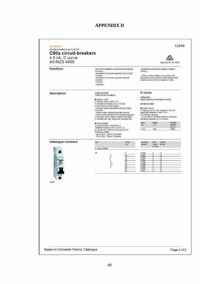
APPENDIX D MCB DATASHEET ................................................................ 40
APPENDIX E CURRENT TRANSFORMER DATASHEET ........................ 41

vii
LIST OF FIGURES Figure 1: Illustration of Earth Fault Conditions ............................................................... 4
Figure 2: Residual Current Circuit Breaker ..................................................................... 7
Figure 3: RCD Basic Operation Diagram ........................................................................ 7
Figure 4: Miniature Circuit Breaker ................................................................................. 8
Figure 5: Current Sensor .................................................................................................. 9
Figure 6: Solenoid Plunger .............................................................................................. 10
Figure 7: Project Flowchart .............................................................................................. 11
Figure 8: System Flowchart ............................................................................................. 13
Figure 9: Simple Domestic Electrical Wiring Diagram ................................................... 14
Figure 10: Fault Location Detection Process Flowchart .................................................. 15
Figure 11: Prototype Layout Design ................................................................................ 17
Figure 12: Circuit Diagram of the Prototype ................................................................... 18
Figure 13: Sample Current Reading ................................................................................. 19
Figure 14: Test Circuit and CT Connection ..................................................................... 20
Figure 15: Normal Condition Testing .............................................................................. 21
Figure 16: Auto-Reset ELCB Simulation Test ................................................................ 22
Figure 17: MCB Check Operation ................................................................................... 23
Figure 18: Unknown Fault with MCB Off ....................................................................... 23
Figure 19: Fault at MCB 1 ............................................................................................... 24
Figure 20: Unknown Fault with MCB On ....................................................................... 24
Figure 21: Overall View of the Prototype ........................................................................ 25
Figure 22: DC Motors Configuration ............................................................................... 26
Figure 23: Normal Condition of the Prototype ................................................................ 26
Figure 24: Actual Auto-Reset ELCB Test ....................................................................... 27
Figure 25: Fault Location Detection Test ........................................................................ 28
LIST OF TABLES Table 1: Hardware Required and Its Functionality .......................................................... 16
Table 2: Software Required and Its Functionality ........................................................... 16
Table 3: Current Sensor Test Result ................................................................................ 20
Table 4: LED Function ..................................................................................................... 21

viii
LIST OF ABBREVIATIONS AC Alternating Current
CT Current Transformer
DC Direct Current
ELCB Earth Leakage Circuit Breaker
MCB Miniature Circuit Breaker
RCBO Residual Current Circuit Breaker with Overload
RCCB Residual Current Circuit Breaker
RCD Residual Circuit Device
SP Solenoid Plunger

1
CHAPTER 1
PROJECT BACKGROUND
1.1 Background of Study
Power reliability and continuity is very important and critical to a domestic
building. There are electrical equipments and appliances which need to be continuously
turned on even when the occupants leave the building for a period of time such as alarm
system, refrigerator and aquarium ventilation system. However electrical fault may
occur in a system that leads to unexpected power outages. Automatic fault location
detection needs to be designed to isolate the permanent fault from the system and
prevent from greater problem. Therefore, a mechanism and program can be designed to
automatically detect fault location at Miniature Circuit Breaker (MCB), isolate it and
reset the Earth Leakage Circuit Breaker (ELCB) in order to restore the supply. A project
done in one of university regarding the automatic ELCB, but the fault location detection
is not yet being developed. This project will merge the automatic ELCB and automatic
fault location together in a single system and prototype.
1.2 Problem Statement
Tripping of ELCB when there is no occupant inside may lead to undesired
circumstances. The critical appliances such as aquarium, refrigerator and alarm system
need a continuous supply of electricity to operate. The problem comes when the ELCB
trips when no occupants in the house for a period of time. If the power supply is
blackout, operation of critical equipment such as alarm system will be instantaneously
terminated. Loss of electricity supply may also contribute to property loss due to
equipment failure such as dying of exotic fish and food damage.

2
ELCB may also trip when fault occurs in the internal wiring. When electrical
tripping is occurring, ELCB will break the supply to all feeders (appliances). An
automatic system to restore the supply by turning back on the ELCB is required. But
when there is a permanent fault exist is the system, the ELCB would not be able to be
turned back on as it will trip again due to the permanent fault.
1.3 Project Objectives
The objectives of this project are:
• To improvise previous project in which the function is limited to only reset the
ELCB automatically without isolating the fault.
• To develop a mechanism and program to detect the fault location, isolate it and
automatically reset the ELCB.
• To produce a more efficient and reliable functioning prototype.
1.4 Scope of study
This project requires deep understanding in the power system basic theory and
domestic electrical wiring configuration. The main focus is determining the location of
fault in a wiring system where it is important in designing an automatic breaker which
can handle permanent fault and able to isolate the fault.
Major scopes of work for this project are:
• Design system for fault location detection
• Improvising ELCB auto-reset mechanism
• Develop a working prototype to simulate real application and situation
3
CHAPTER 2
LITERATURE REVIEW
2.1 Domestic Electrical System
Domestic electrical system refers to electrical system developed for home and
residential, which mostly utilizes single-phase type of power system. In electrical
engineering, the term single phase electric power system refers to the distribution of
alternating current (AC) electric power using a system in which all the voltages of the
supply vary in unison [1].
A single phase load may be powered from a three-phase distribution system
either by connection between a phase and neutral (120 V or 230 V). Generally in
Malaysia, Tenaga Nasional Berhad (TNB) supplies single-phase 2-wires with rating of
240 V to domestic premises [2]. On higher voltage system, a single phase transformer is
use to supply a low voltage system especially in rural area, where the cost of three phase
distribution network is high [3].
Although single phase system has safety (earth conductor) but this can’t ensure
perfect protection to the electrical circuit, electrical equipment and also human life from
high voltage. In Malaysia, according to Utusan Malaysia (2011), it is about 191 people
died out of 405 electrical accidents due to electrical faults occurred recorded for year of
2005 until 2011 [4]. Therefore, as part of increasing electrical protection and reducing
accidents due to electrical faults, installation of protection device such as circuit breaker
is required besides exposure on electrical safety and hazard towards the public.
4
This project requires clear understanding on the common fault and the basic
protection system of domestic or home electrical system. Both entities are important to
be understood as to overview the effects of electrical faults and poor electrical
protection system, which commonly lead to injury or death due to electrical shock
besides technical and economical losses due to equipment failure.
2.2 Common Domestic Electrical Fault
In domestic premises, there are three common factors that cause electrical problems
at home that might lead to fatality or equipment failure [5], which are:
• Faulty wiring in the house
• Improper flexible cords
• Faulty appliance
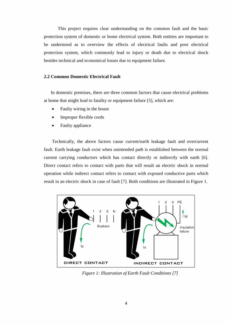
Technically, the above factors cause current/earth leakage fault and overcurrent
fault. Earth leakage fault exist when unintended path is established between the normal
current carrying conductors which has contact directly or indirectly with earth [6].
Direct contact refers to contact with parts that will result an electric shock in normal
operation while indirect contact refers to contact with exposed conductive parts which
result in an electric shock in case of fault [7]. Both conditions are illustrated in Figure 1.
Figure 1: Illustration of Earth Fault Conditions [7]
5
Ovecurrent fault occurred when the current exceeds the rated current carrying
capacity of the conductor [8] and can be divided into two types: overload and short
circuit. Overload faults are caused by excessive loads where a larger than intended
electric current exists throughout a conductor, leading to an excessive heat generation,
and the risk of fire or equipment damage [8, 9]. While a short circuit in an electrical
circuit that allows a current to travel along an unintended path, often where essentially
no (or very low) electrical impedance is encountered [10].
2.3 Domestic Electrical Protection
In general, for domestic electrical protection which utilizes single-phase power
system will concentrate on protecting electrical circuits from overcurrent and ground
faults. Circuit breaker such as Miniature Circuit Breaker (MCB) is preferred for
overcurrent fault and earth leakage circuit breaker (ELCB) or residual current circuit
breaker (RCCB) used to protect from ground fault.
Most houses nowadays are protected by circuit breakers rather than fuses [10],
since fuses have to be replaced when it blows and sometimes fuses could create
overheat in a circuit [11]. A circuit breaker that “tripped” can be mechanically reset or
switched on to resume operations once the problem occurred has been resolved. Circuit
breakers also protect branch circuits with size range of 120 Volts or 230 Volts [12].
ELCB or Earth Leakage Circuit Breaker is designed to detect electric current
leakage in a house wiring and protect from earthing problems. When amount of leaked
current exceeds the value set by ELCB for instance 30 mA, the ELCB will then isolate
supply from internal circuits [13]. This is done automatically within a fraction of a
second of the leakage being detected, before the magnitude of the leakage current
reaches a level that can cause serious injuries or electrocution. With a proper use of
ELCB, the possibility of serious injuries due to electric shock to a person who
accidentally come into contact with energized metal casing of an appliance is
minimized.
6
2.4 Earth Leakage Circuit Breaker
As briefly explained in Chapter 2.3, an Earth Leakage Circuit Breaker or
acronym as ELCB is a safety device which used in electrical installations with high
earth impedance to prevent shock. An ELCB provides a safer electrical installation
since it shut the power off when dangerous conditions occur [14]. For instance, if a
person touches something, typically a metal part on faulty electrical equipment, which
is at a significant voltage relative to the earth, electrical current will flow through that
person to the earth. The current that flows are too small to blow an electrical fuse but
still very harmful and could cause death. An ELCB has the ability to detect even a small
current flow to earth (earth leakage) and disconnects the breaker.
There are two types of ELCB which are:
• Voltage operand
• Current operand
Voltage operated ELCB operates at a detected potential of around 50 V to open
a main breaker and isolate the supply from the protected premises [15]. But since it
operates at 50 V, it is not been used in newer domestic wiring as the 50 V is still
considered as safe voltage for alternating current [16]. For newer domestic wiring,
current operated ELCB is more preferable to be installed in premises due to reliability.
Current-operated ELCB is generally known as Residual Current Device (RCD). The
function is similar, which protect against earth leakage, though the details and method
of operation are different [14].
2.5 Residual Current Device
Residual Current Device or simply RCD, as in Figure 2, is nowadays firmly
established worldwide as primary means of providing protection against electrocution
and fires that caused by electrical faults. Less than one quarter of an amp (250 mA)
leaking from a faulty installation can generate sufficient heat to start a fire (the heating
effect is proportional to the current squared), or if leaking through a human body for
only 200 mS can cause heart fibrillation and subsequent death [17]. In short, RCD is a
protection device used to disconnect circuit when residual current reaches or exceed
device rated residual current.

7
Figure 2: Residual Current Circuit Breaker [18]
The RCD operates by measuring the current balance between two conductors
using a differential current transformer, as illustrated in Figure 3. Difference between
the current flowing out the live wire (to the load) and the returning current (from the
load) through the neutral wire, also known as residual current, is measured. Current
leakage said to be exist when the difference sum measured is not equal to zero and the
device will open it contacts [18]. As according to the IEC, RCD in buildings must be
installed with residual current rating of 30 mA for protection against shock [19]. The
RCD will trip if the residual current or the difference between current flowing in an out
exceeds 30 mA.
Figure 3: RCD Basic Operation Diagram [17]
8
2.6 Miniature Circuit Breaker
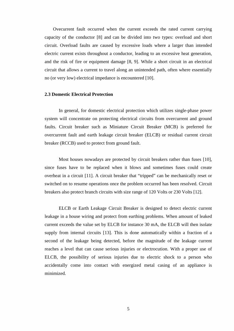
Miniature circuit breakers or MCB, as in Figure 4, are commonly used in the
electrical consumer units of domestic dwellings and small industrial premises to protect
and control the electrical supply to respective electrical circuits of the building. This
resettable protective device also designed to isolate a circuit during an overcurrent (both
overload and short circuit) event without using fuse [20]. MCB is preferable for
building protection rather than using fuse because of its resettable capability [11].
Figure 4: Miniature Circuit Breaker [20]
MCB typically comprises an electrical contact mounted on a movable contact
carrier which rotates away from a stationary contact in order to interrupt the current
path. The mechanism of operation includes a movable handle that extends at the outside
of the housing. The handle has basically three stable positions: on, off, and tripped.
These three positions are to indicate the condition of the contacts when the handle is
viewed. The trip mechanism is automatically releasable to effect tripping operations and
is manually resettable following tripping operations. The mechanism will respond to
instantaneous high current to open the contact and therefore interrupts the current flow
[20].
9
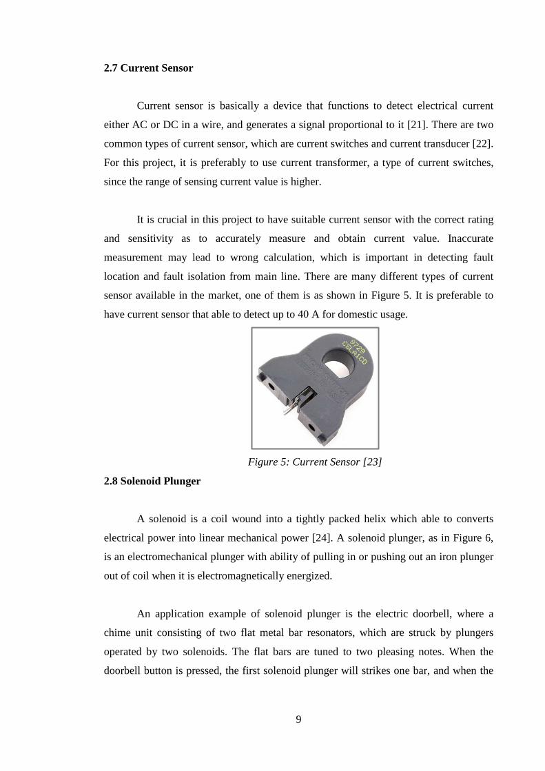
2.7 Current Sensor
Current sensor is basically a device that functions to detect electrical current
either AC or DC in a wire, and generates a signal proportional to it [21]. There are two
common types of current sensor, which are current switches and current transducer [22].
For this project, it is preferably to use current transformer, a type of current switches,
since the range of sensing current value is higher.
It is crucial in this project to have suitable current sensor with the correct rating
and sensitivity as to accurately measure and obtain current value. Inaccurate
measurement may lead to wrong calculation, which is important in detecting fault
location and fault isolation from main line. There are many different types of current
sensor available in the market, one of them is as shown in Figure 5. It is preferable to
have current sensor that able to detect up to 40 A for domestic usage.
Figure 5: Current Sensor [23]
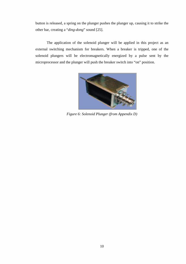
2.8 Solenoid Plunger
A solenoid is a coil wound into a tightly packed helix which able to converts
electrical power into linear mechanical power [24]. A solenoid plunger, as in Figure 6,
is an electromechanical plunger with ability of pulling in or pushing out an iron plunger
out of coil when it is electromagnetically energized.
An application example of solenoid plunger is the electric doorbell, where a
chime unit consisting of two flat metal bar resonators, which are struck by plungers
operated by two solenoids. The flat bars are tuned to two pleasing notes. When the
doorbell button is pressed, the first solenoid plunger will strikes one bar, and when the
10
button is released, a spring on the plunger pushes the plunger up, causing it to strike the
other bar, creating a “ding-dong” sound [25].
The application of the solenoid plunger will be applied in this project as an
external switching mechanism for breakers. When a breaker is tripped, one of the
solenoid plungers will be electromagnetically energized by a pulse sent by the
microprocessor and the plunger will push the breaker switch into “on” position.
Figure 6: Solenoid Plunger (from Appendix D)

11
CHAPTER 3
METHODOLOGY
3.1 Project Flow
A good project planning will initiate a good project framework, which would
lead to a success of a project. As illustrated in Figure 7, the project is systematically
planned to meet with the specific timeline.
Figure 7: Project Flowchart
System Implementation & Prototype Fabrication
Overall System Configuration & Testing
Software Development & Components Selection
System Planning & Designing
Information & Data Gathering
NO
YES
System functioning?

12
For this project, the sequence begins with Information and Data Gathering of
problem stated as well as getting clear view and understanding on the domestic
electrical wiring, which includes information regarding types of breakers used and
hardware selected. The, proceed with System Plan and Design phase. This is where the
overall system is being drafted, the software and hardware of the system and the overall
system operation.
In Software Development and Components Selection phase includes
programming development to control the whole protection system and components that
needed in designing and developing the prototype. Once the system is completely
configured and the hardware and software is synchronized, the system functionality will
be tested. If passed, system is ready to be implemented and fully developed as a
functional prototype. Vice versa, the system will be reconfigured back and troubleshoot.
3.2 System Plan of Operation
In the System Plan & Design stage, an automatic system is designed for
domestic electrical system to auto-reset ELCB and auto-detection if any permanent fault
occurred. The system operation is divided into two parts: power recovery and fault
location detection. In Power Recovery part, it covers about the automatic reset of ELCB,
which restore the supply and the Fault Location Detection part will covers how the
permanent fault is being detected and finally isolate it from the main system.
3.2.1 Power Recovery
Power recovery is a process of turning back the power on after the power is out
or shut down for a period of time as result of tripping or faulty. Quick power recovery is
important when there are equipments or electrical appliances which require continuous
power supply such as refrigerator, water pump for aquarium, alarm system and few
others. Currently, as for home electrical system, power recovery is manually done. In
other words, a person has to switch on the main switch in distribution board to turn the
power back on after tripping occurred. It becomes a problem when the residents or
owner of the house is out for a period of time and no one is there to turn the power back
on.
13
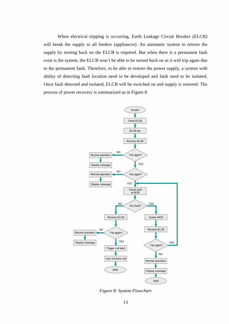
When electrical tripping is occurring, Earth Leakage Circuit Breaker (ELCB)
will break the supply to all feeders (appliances). An automatic system to restore the
supply by turning back on the ELCB is required. But when there is a permanent fault
exist is the system, the ELCB won’t be able to be turned back on as it will trip again due
to the permanent fault. Therefore, to be able to restore the power supply, a system with
ability of detecting fault location need to be developed and fault need to be isolated.
Once fault detected and isolated, ELCB will be switched on and supply is restored. The
process of power recovery is summarized as in Figure 8.
Figure 8: System Flowchart
14
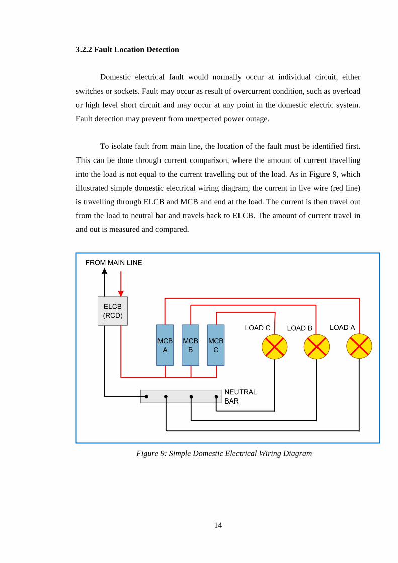
3.2.2 Fault Location Detection
Domestic electrical fault would normally occur at individual circuit, either
switches or sockets. Fault may occur as result of overcurrent condition, such as overload
or high level short circuit and may occur at any point in the domestic electric system.
Fault detection may prevent from unexpected power outage.
To isolate fault from main line, the location of the fault must be identified first.
This can be done through current comparison, where the amount of current travelling
into the load is not equal to the current travelling out of the load. As in Figure 9, which
illustrated simple domestic electrical wiring diagram, the current in live wire (red line)
is travelling through ELCB and MCB and end at the load. The current is then travel out
from the load to neutral bar and travels back to ELCB. The amount of current travel in
and out is measured and compared.
Figure 9: Simple Domestic Electrical Wiring Diagram
15
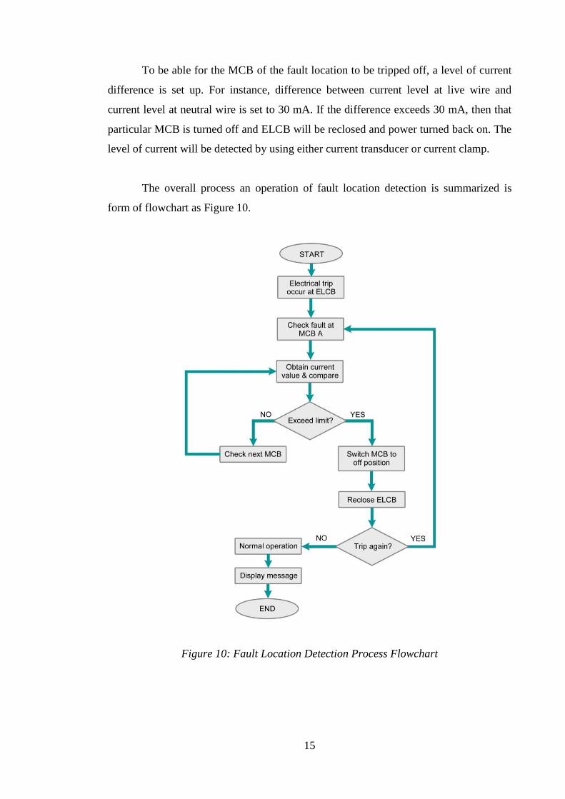
To be able for the MCB of the fault location to be tripped off, a level of current
difference is set up. For instance, difference between current level at live wire and
current level at neutral wire is set to 30 mA. If the difference exceeds 30 mA, then that
particular MCB is turned off and ELCB will be reclosed and power turned back on. The
level of current will be detected by using either current transducer or current clamp.
The overall process an operation of fault location detection is summarized is
form of flowchart as Figure 10.
Figure 10: Fault Location Detection Process Flowchart
16
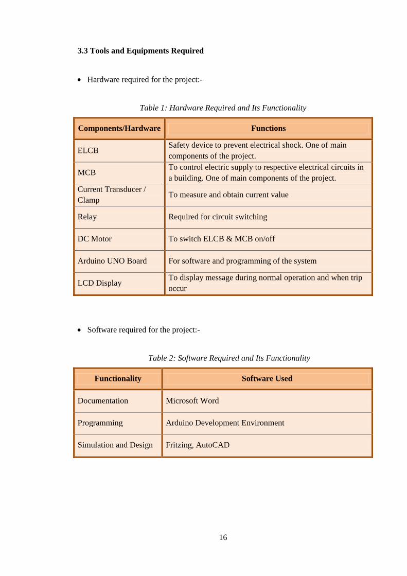
3.3 Tools and Equipments Required
• Hardware required for the project:-
Table 1: Hardware Required and Its Functionality
Components/Hardware Functions
ELCB Safety device to prevent electrical shock. One of main components of the project.
MCB To control electric supply to respective electrical circuits in a building. One of main components of the project.
Current Transducer / Clamp
To measure and obtain current value
Relay Required for circuit switching
DC Motor To switch ELCB & MCB on/off
Arduino UNO Board For software and programming of the system
LCD Display To display message during normal operation and when trip occur
• Software required for the project:-
Table 2: Software Required and Its Functionality
Functionality Software Used
Documentation Microsoft Word
Programming Arduino Development Environment
Simulation and Design Fritzing, AutoCAD
17
3.5 Components Selection
Components are very important features in this project. Selection of components
is made through literature review done earlier to ensure correct rating of component that
going to be used for the project. Listed below are the main components required for this
project:
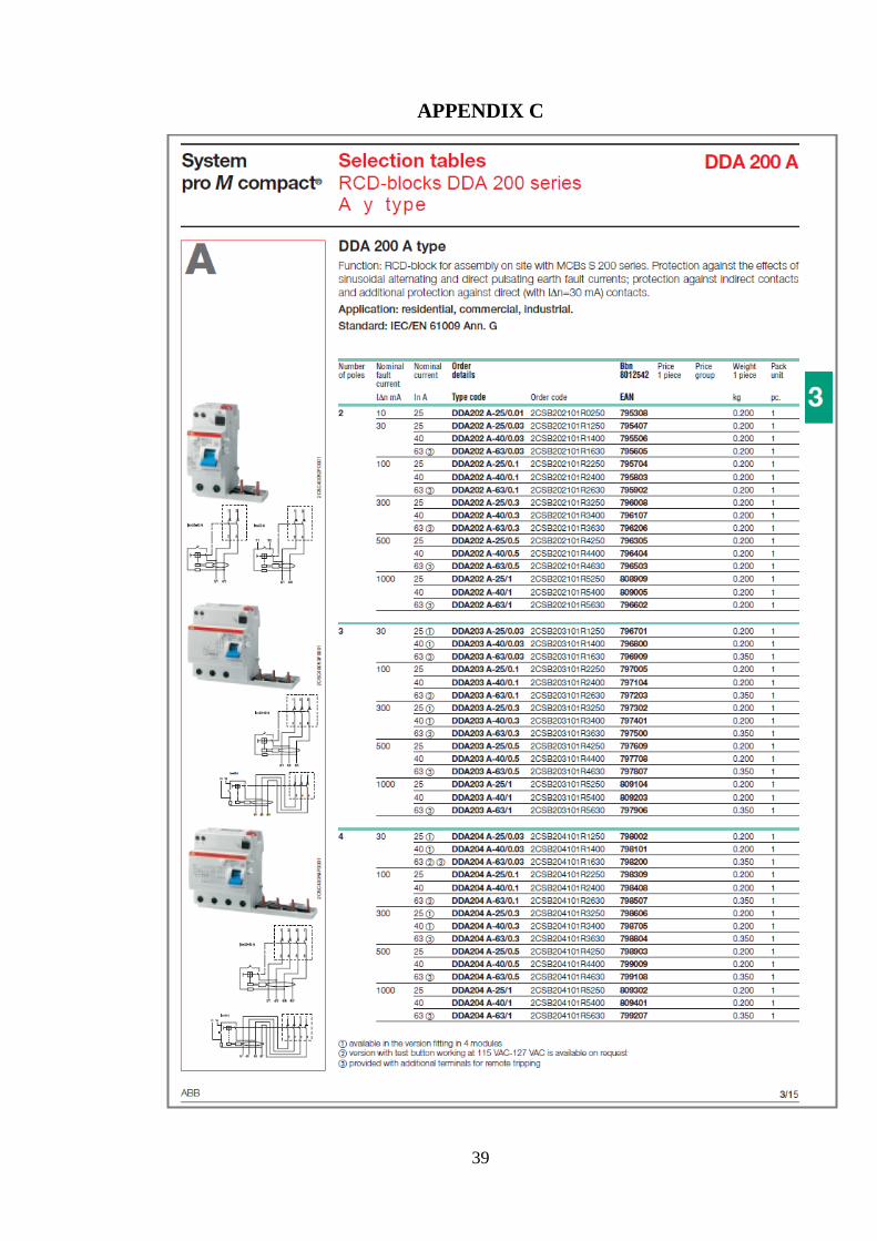
• Residual Current Circuit Breaker (see Appendix C)
• Miniature Circuit Breaker (see Appendix D)
• Split Core Current Sensor (see Appendix E)
• 12V DC Motor
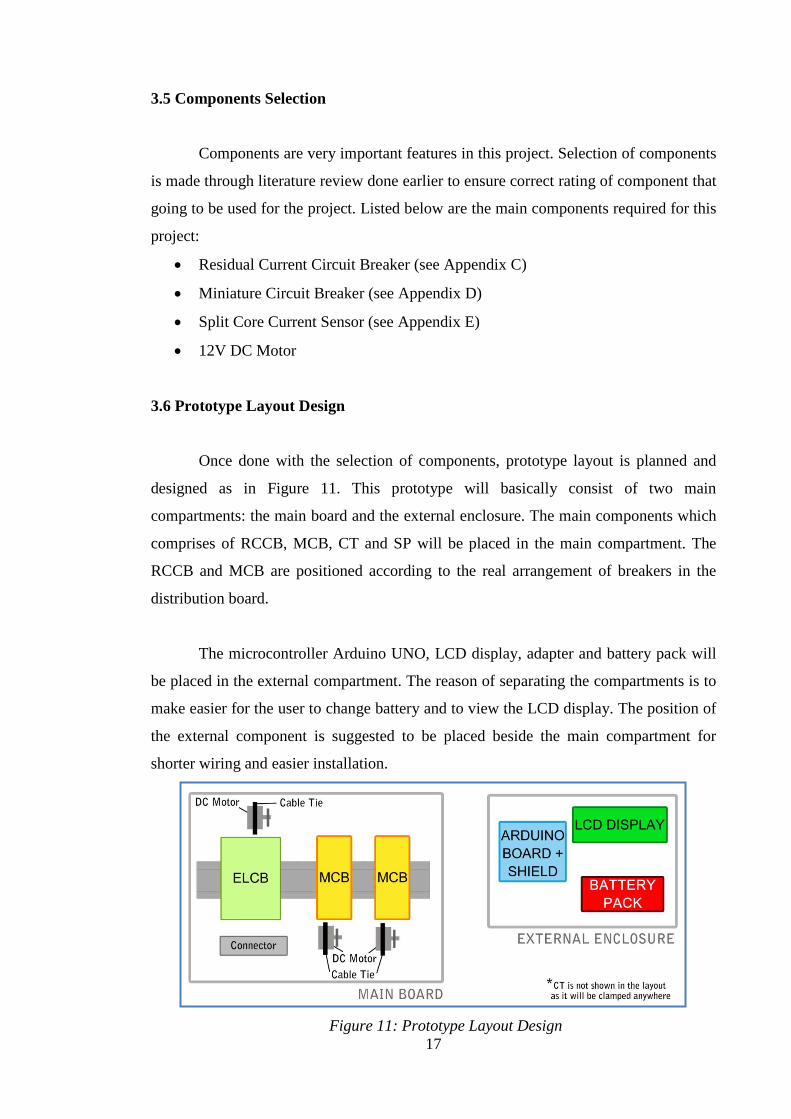
3.6 Prototype Layout Design
Once done with the selection of components, prototype layout is planned and
designed as in Figure 11. This prototype will basically consist of two main
compartments: the main board and the external enclosure. The main components which
comprises of RCCB, MCB, CT and SP will be placed in the main compartment. The
RCCB and MCB are positioned according to the real arrangement of breakers in the
distribution board.
The microcontroller Arduino UNO, LCD display, adapter and battery pack will
be placed in the external compartment. The reason of separating the compartments is to
make easier for the user to change battery and to view the LCD display. The position of
the external component is suggested to be placed beside the main compartment for
shorter wiring and easier installation.
Figure 11: Prototype Layout Design
18
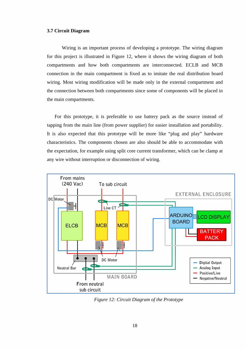
3.7 Circuit Diagram
Wiring is an important process of developing a prototype. The wiring diagram
for this project is illustrated in Figure 12, where it shows the wiring diagram of both
compartments and how both compartments are interconnected. ECLB and MCB
connection in the main compartment is fixed as to imitate the real distribution board
wiring. Most wiring modification will be made only in the external compartment and
the connection between both compartments since some of components will be placed in
the main compartments.
For this prototype, it is preferable to use battery pack as the source instead of
tapping from the main line (from power supplier) for easier installation and portability.
It is also expected that this prototype will be more like “plug and play” hardware
characteristics. The components chosen are also should be able to accommodate with
the expectation, for example using split core current transformer, which can be clamp at
any wire without interruption or disconnection of wiring.
Figure 12: Circuit Diagram of the Prototype
19
CHAPTER 4
RESULTS AND DISCUSSION
4.1 Current Sensor Functionality Test
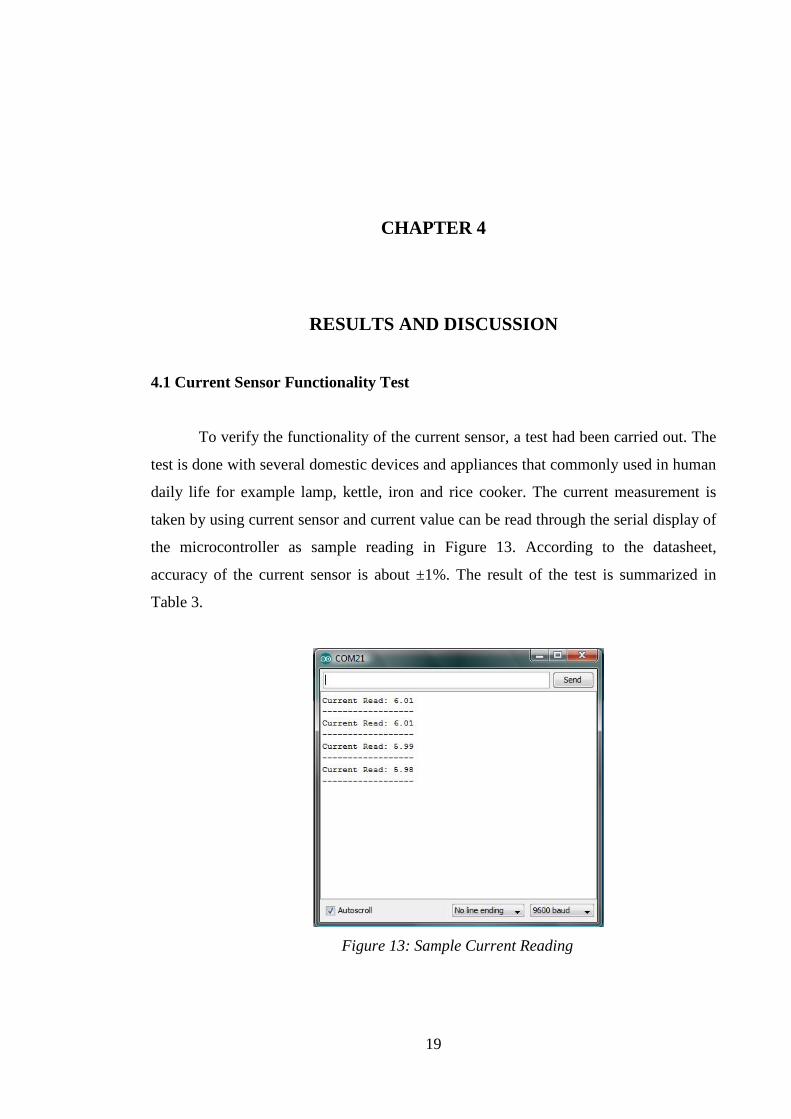
To verify the functionality of the current sensor, a test had been carried out. The
test is done with several domestic devices and appliances that commonly used in human
daily life for example lamp, kettle, iron and rice cooker. The current measurement is
taken by using current sensor and current value can be read through the serial display of
the microcontroller as sample reading in Figure 13. According to the datasheet,
accuracy of the current sensor is about ±1%. The result of the test is summarized in
Table 3.
Figure 13: Sample Current Reading
20
Table 3: Current Sensor Test Result
Device Power (Watt) Calculated Current (Amp)
Current Reading (Amp)
Lamp 70 0.292 0.350
Rice Cooker 450 1.875 1.887
Iron 1000 4.167 4.204
Kettle 1500 6.250 6.265
From the result in Table 2, the reading of the current sensor is in range of
accuracy as in datasheet. The current sensor is valid to be used as measurement device
in this project.
4.2 Simulation Test
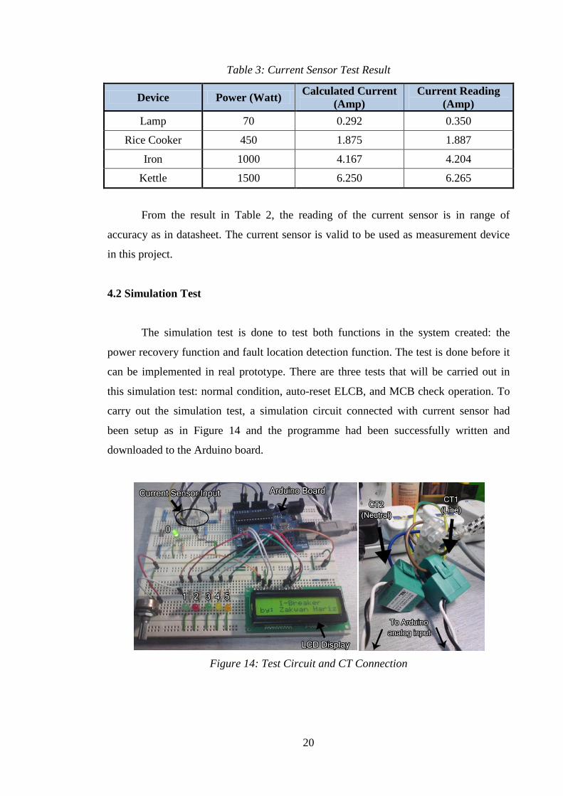
The simulation test is done to test both functions in the system created: the
power recovery function and fault location detection function. The test is done before it
can be implemented in real prototype. There are three tests that will be carried out in
this simulation test: normal condition, auto-reset ELCB, and MCB check operation. To
carry out the simulation test, a simulation circuit connected with current sensor had
been setup as in Figure 14 and the programme had been successfully written and
downloaded to the Arduino board.
Figure 14: Test Circuit and CT Connection
21
In the test circuit designed, the desired hardware (motor, solenoid and hand
phone) that should be used in real prototype is currently represented by LED, for testing
purpose. The function of each LED is summarized as in Table 4.
Table 4: LED Function
LED Number Function
0 Indicator for power supply
1 Indicator for normal condition
2 Indicator for fault condition
3 Represent DC motor, for ELCB auto-reset
4 Represent DC motor, for triggering MCB off
5 Represent hand phone, to make able for call alert
4.2.1 Normal Condition Test
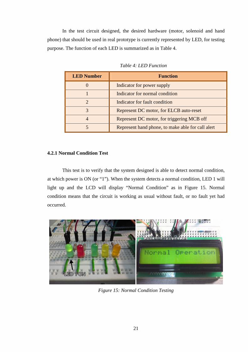
This test is to verify that the system designed is able to detect normal condition,
at which power is ON (or “1”). When the system detects a normal condition, LED 1 will
light up and the LCD will display “Normal Condition” as in Figure 15. Normal
condition means that the circuit is working as usual without fault, or no fault yet had
occurred.
Figure 15: Normal Condition Testing
22
4.2.2 Auto-Reset ELCB Test
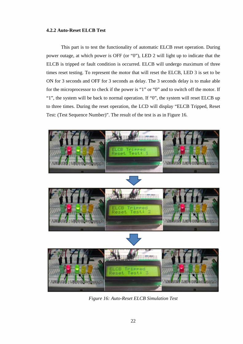
This part is to test the functionality of automatic ELCB reset operation. During
power outage, at which power is OFF (or “0”), LED 2 will light up to indicate that the
ELCB is tripped or fault condition is occurred. ELCB will undergo maximum of three
times reset testing. To represent the motor that will reset the ELCB, LED 3 is set to be
ON for 3 seconds and OFF for 3 seconds as delay. The 3 seconds delay is to make able
for the microprocessor to check if the power is “1” or “0” and to switch off the motor. If
“1”, the system will be back to normal operation. If “0”, the system will reset ELCB up
to three times. During the reset operation, the LCD will display “ELCB Tripped, Reset
Test: (Test Sequence Number)”. The result of the test is as in Figure 16.
Figure 16: Auto-Reset ELCB Simulation Test
23
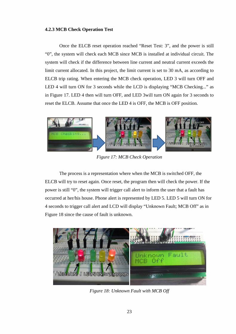
4.2.3 MCB Check Operation Test
Once the ELCB reset operation reached “Reset Test: 3”, and the power is still
“0”, the system will check each MCB since MCB is installed at individual circuit. The
system will check if the difference between line current and neutral current exceeds the
limit current allocated. In this project, the limit current is set to 30 mA, as according to
ELCB trip rating. When entering the MCB check operation, LED 3 will turn OFF and
LED 4 will turn ON for 3 seconds while the LCD is displaying “MCB Checking...” as
in Figure 17. LED 4 then will turn OFF, and LED 3will turn ON again for 3 seconds to
reset the ELCB. Assume that once the LED 4 is OFF, the MCB is OFF position.
Figure 17: MCB Check Operation
The process is a representation where when the MCB is switched OFF, the
ELCB will try to reset again. Once reset, the program then will check the power. If the
power is still “0”, the system will trigger call alert to inform the user that a fault has
occurred at her/his house. Phone alert is represented by LED 5. LED 5 will turn ON for
4 seconds to trigger call alert and LCD will display “Unknown Fault; MCB Off” as in
Figure 18 since the cause of fault is unknown.
Figure 18: Unknown Fault with MCB Off
24
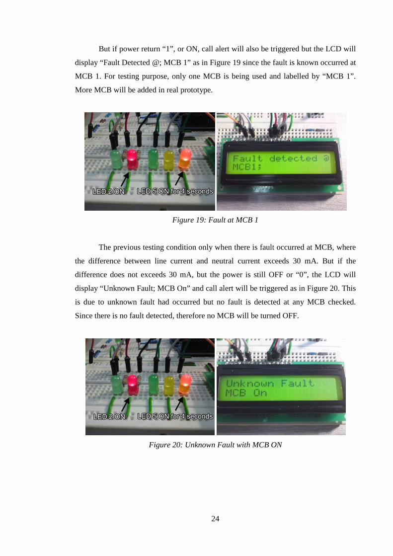
But if power return “1”, or ON, call alert will also be triggered but the LCD will
display “Fault Detected @; MCB 1” as in Figure 19 since the fault is known occurred at
MCB 1. For testing purpose, only one MCB is being used and labelled by “MCB 1”.
More MCB will be added in real prototype.
Figure 19: Fault at MCB 1
The previous testing condition only when there is fault occurred at MCB, where
the difference between line current and neutral current exceeds 30 mA. But if the
difference does not exceeds 30 mA, but the power is still OFF or “0”, the LCD will
display “Unknown Fault; MCB On” and call alert will be triggered as in Figure 20. This
is due to unknown fault had occurred but no fault is detected at any MCB checked.
Since there is no fault detected, therefore no MCB will be turned OFF.
Figure 20: Unknown Fault with MCB ON

25
4.3 Prototype Development
Results from the simulation test had verified that the system developed is well-
functioning. The system developed will then be implemented in real prototype and
hardware. Figure 21 shows the overall view of the prototype designed.
Figure 21: Overall View of the Prototype
The prototype is designed with one ELCB and two MCBs to represent the home
distribution board. There are two main compartments in the prototype, the main board
and the external enclosure. The main board is where the ELCB, MCBs and DC motors
are placed, while the external enclosure contains batteries, Arduino board, LCD display
and other electronic components. Figure 22 shows the DC motors that are being used
for triggering mechanism. Solenoid plungers are replaced by DC motor due to several
circumstances.
A nylon cable is attached between each DC motors with the ELCB and MCBs
for the triggering mechanism. Each DC motor will be driven by a motor drive,
comprises of N-channel power MOSFET, diode, resistor and connector.
MAIN BOARD
EXTERNAL ENCLOSURE
26
Figure 22: DC Motors Configuration
4.4 Prototype Test
The designed prototype is ready to be tested to observe its actual functionality.
The tests done are similar with the simulation test and results are as in the following
sections.
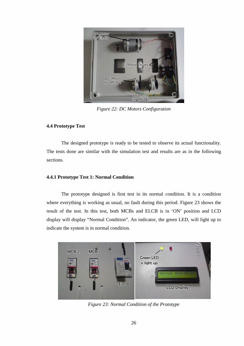
4.4.1 Prototype Test 1: Normal Condition
The prototype designed is first test in its normal condition. It is a condition
where everything is working as usual, no fault during this period. Figure 23 shows the
result of the test. In this test, both MCBs and ELCB is in ‘ON’ position and LCD
display will display “Normal Condition”. An indicator, the green LED, will light up to
indicate the system is in normal condition.
Figure 23: Normal Condition of the Prototype
27
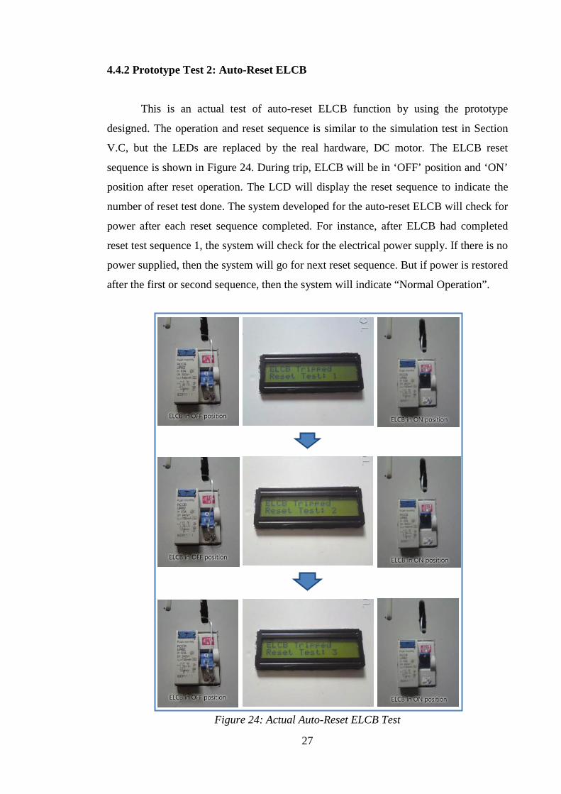
4.4.2 Prototype Test 2: Auto-Reset ELCB
This is an actual test of auto-reset ELCB function by using the prototype
designed. The operation and reset sequence is similar to the simulation test in Section
V.C, but the LEDs are replaced by the real hardware, DC motor. The ELCB reset
sequence is shown in Figure 24. During trip, ELCB will be in ‘OFF’ position and ‘ON’
position after reset operation. The LCD will display the reset sequence to indicate the
number of reset test done. The system developed for the auto-reset ELCB will check for
power after each reset sequence completed. For instance, after ELCB had completed
reset test sequence 1, the system will check for the electrical power supply. If there is no
power supplied, then the system will go for next reset sequence. But if power is restored
after the first or second sequence, then the system will indicate “Normal Operation”.
Figure 24: Actual Auto-Reset ELCB Test
28
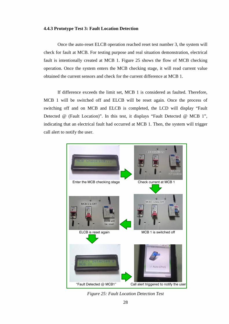
4.4.3 Prototype Test 3: Fault Location Detection
Once the auto-reset ELCB operation reached reset test number 3, the system will
check for fault at MCB. For testing purpose and real situation demonstration, electrical
fault is intentionally created at MCB 1. Figure 25 shows the flow of MCB checking
operation. Once the system enters the MCB checking stage, it will read current value
obtained the current sensors and check for the current difference at MCB 1.
If difference exceeds the limit set, MCB 1 is considered as faulted. Therefore,
MCB 1 will be switched off and ELCB will be reset again. Once the process of
switching off and on MCB and ELCB is completed, the LCD will display “Fault
Detected @ (Fault Location)”. In this test, it displays “Fault Detected @ MCB 1”,
indicating that an electrical fault had occurred at MCB 1. Then, the system will trigger
call alert to notify the user.
Enter the MCB checking stage Check current at MCB 1
ELCB is reset again MCB 1 is switched off
“Fault Detected @ MCB1” Call alert triggered to notify the user
Figure 25: Fault Location Detection Test
29
CHAPTER 5
CONCLUSION AND RECOMMENDATIONS
5.1 Conclusion
This project, Automated Electrical Protection System or Auto-EProS can be
considered as a new invention in electrical protection field. Since the progress can be
said is on schedule and the tests are done successfully, the project seems going to be a
successful project. Lots of improvements had been made from previous project as
according to methodology suggested and studies done. This project requires high
understanding in power system as well as vast knowledge in electronic to accurately
measure the parameters and make it able to communicate with electronic components.
Towards the end of this project, it is expected that this project will be significant in
terms of technical and economical besides commercially valued.
5.2 Recommendations
Towards the end of this project, a few recommendations are to be made as
followings in order to improve the efficiency and effectiveness of the system developed:
• Use different type of triggering mechanism, e.g. use solenoid instead of dc
motor
• Develop the system to cater the plug-and-play characteristics
• If possible, use differential current transformer instead of split core current
transformer to directly obtain the current difference value
• The system may be developed for three phase system, for industrial purposes
30
REFERENCES
[1] Stevenson, William D., Jr., “Elements of Power Systems Analysis”, McGraw-Hill
Electrical And Electronic Engineering Series (3rd Ed.), New York, 1975
[2] “TNB Electricity System”. [Online] Retrieved from
http://www.tnb.com.my/business/for-housing-developers-electrical-
contractors/tnb-electricity-system.html
[3] “Single-Phase Electric Power”. [Online] Retrieved from
http://en.wikipedia.org/Single-phase_electric_power
[4] “191 Mati Akibat Kejutan Elektrik”, Newspaper Article, 2011. [Online] Retrieved
from
http://www.utusan.com.my/utusan/info.asp?y=2011&dt=0415&pub=Utusan_Mal
aysia&sec=Dalam_Negeri&pg=dn_10.htm
[5] “Energy Guide Book (For Consumers)”, Published for National Energy Efficient
Awareness Campaign (SWITCH), WECAM, 2009
[6] QO and QOB Miniature Circuit Breakers with Ground Fault Protection,
Schneider Electric, 2009
[7] “Direct and Indirect Contact” [Online] Retreived from http://www.electrical-
installation.org/enwiki/Direct_and_indirect_contact
[8] “Electrical Safety Hazards Handbook”, Littelfuse USA, 2005
[9] “Overcurrent”. [Online] Retrieved from http://en.wikipedia.org/wiki/Overcurrent
[10] “Electrical Safety Handbook”, Electrical Safety Foundation International (ESFi),
pg.6
31
[11] “Difference between Fuse and Circuit Breaker”. [Online] Retrieved from
http://www.wisegeek.com/what-is-the-difference-between-a-fuse-and-a-circuit-
breaker.htm
[12] Donnelly E.L., “Electrical Installation: Theory and Practice”, Thomas Nelson and
Sons Ltd. (3rd Ed.), 1985
[13] “Residential Wiring Guide”, 10th Ed., Manitoba Hydro, 2009
[14] ‘Earth Leakage Circuit Breaker”. [Online] Retrieved from
http://en.wikipedia.org/wiki/Earth_leakage_circuit_breaker
[15] Shelton S., “Electrical Installlations”, Nelson Thrones (3rd ed.), 2004
[16] Szoncso F., “Electrical Safety Organisations at CERN”, CERN Safety
Commission
[17] “How Does an RCB Work?” Power Breaker, Article
[18] “Residual Current Device”. [Online] Retrieved from
http://en.wikipedia.org/wiki/Residual-current_device
[19] “Residual Current Devices in LV”, Cahier Technique no. 114, Schneider Electric,
2006
[20] “Miniature Circuit Breakers: Application Guide”, ABB Inc., USA, Apr 2009
[21] “What Is Current Sensor and How It Is Used?” [Online] Retrieved from
http://www.ti.com/analog/docs/microsite.tsp?sectionId=560&tabId=2180µs
iteId=7
[22] “Current Sensing” [Online] Retrieved from
http://www.nktechnologies.com/current-sensing.html

32
[23] “Open Loop Hall Effect Current Sensor” [Online] Retrieved from
http://www.directindustry.com/prod/honeywell-sensing-and-control/open-loop-
hall-effect-current-sensors-12365-306124.html
[24] Solenoids and Actuators [Online] Retrieved from
http://homepages.which.net/~paul.hills/Solenoids/SolenoidsBody.html
[25] “Wired Doorbells”. [Online] Retrieved from http://en.wikipedia.org/wiki/Doorbell

33
APPENDIX A
No Detail/Week – FYP I 1 2 3 4 5 6
Mid
-Sem
este
r B
reak
7 8 9 10 11 12 13 14
1 Selection of Project Topic
2 Literature Review and Research on Topic Selected
3 Scope and Methodology Analysis
4 Submission of Extended Proposal
5 Prototype Plan & Design: Drafting Stage
6 Proposal Defence
7 Prototype Drafting Continue
8 Interim Report Submission
No Detail/Week – FYP II 1 2 3 4 5 6
Mid
-Sem
este
r B
reak
7 8 9 10 11 12 13 14
1 Software & Hardware Development
2 System Functionality Test
3 System Troubleshooting
4 System Implementation & Prototype Fabrication
5 Draft Report
6 Submission & Completion of Project
34
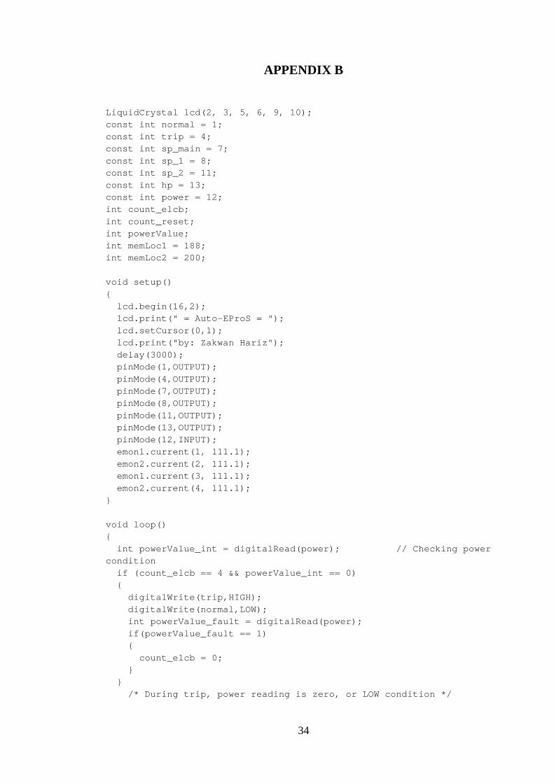
APPENDIX B
LiquidCrystal lcd(2, 3, 5, 6, 9, 10); const int normal = 1; const int trip = 4; const int sp_main = 7; const int sp_1 = 8; const int sp_2 = 11; const int hp = 13; const int power = 12; int count_elcb; int count_reset; int powerValue; int memLoc1 = 188; int memLoc2 = 200; void setup() { lcd.begin(16,2); lcd.print(" = Auto-EProS = "); lcd.setCursor(0,1); lcd.print("by: Zakwan Hariz"); delay(3000); pinMode(1,OUTPUT); pinMode(4,OUTPUT); pinMode(7,OUTPUT); pinMode(8,OUTPUT); pinMode(11,OUTPUT); pinMode(13,OUTPUT); pinMode(12,INPUT); emon1.current(1, 111.1); emon2.current(2, 111.1); emon1.current(3, 111.1); emon2.current(4, 111.1); } void loop() { int powerValue_int = digitalRead(power); // Checking power condition if (count_elcb == 4 && powerValue_int == 0) { digitalWrite(trip,HIGH); digitalWrite(normal,LOW); int powerValue_fault = digitalRead(power); if(powerValue_fault == 1) { count_elcb = 0; } } /* During trip, power reading is zero, or LOW condition */

35
else if(count_elcb != 4 && powerValue_int == 1) { normal_display(); digitalWrite(normal,HIGH); // At normal condition digitalWrite(trip,LOW); //Current Sensor at MCB 1 double Irms_L1 = emon1.calcIrms(1480); // Calculate Irms only double Irms_N1 = emon2.calcIrms(1480); long lineCurrent1 = Irms_L*100; long neutCurrent1 = Irms_N*100; long diff1 = lineCurrent - neutCurrent; EEPROMWriteInt(memLoc1,diff1); //Current Sensor at MCB 1 double Irms_L2 = emon3.calcIrms(1480); // Calculate Irms only double Irms_N2 = emon4.calcIrms(1480); long lineCurrent2 = Irms_L*100; long neutCurrent2 = Irms_N*100; long diff2 = lineCurrent - neutCurrent; EEPROMWriteInt(memLoc2,diff2); count_elcb = 0; int powerValue_0 = digitalRead(power); if (powerValue_0 == 0 && count_elcb == 0) // First trial { lcd.clear(); lcd.print("ELCB Tripped"); lcd.setCursor(0,1); lcd.print("Reset Test: 1"); trip_reset(); delay(2500); } count_elcb = 1; int powerValue_1 = digitalRead(power); if(powerValue_1 == 0 && count_elcb == 1) // Second trial { lcd.clear(); lcd.print("ELCB Tripped"); lcd.setCursor(0,1); lcd.print("Reset Test: 2"); trip_reset(); delay(2500); } count_elcb = 2; int powerValue_2 = digitalRead(power); if(powerValue_2 == 0 && count_elcb == 2) // Third trial { lcd.clear(); lcd.print("ELCB Tripped"); lcd.setCursor(0,1); lcd.print("Reset Test: 3");

36
trip_reset(); delay(2500); } count_elcb = 3; int powerValue_3 = digitalRead(power); if(powerValue_3 == 0 && count_elcb == 3) { lcd.clear(); lcd.print("MCB Checking..."); delay(2000); currentDiff1 = EEPROMReadInt(memLoc1); //read memory from CT 1 currentDiff2 = EEPROMReadInt(memLoc2); //read memory from CT 2 if(currentDiff1 < 300 && currentDiff1 > -300 || currentDiff2 < 300 && currentDiff2 > -300) { lcd.clear(); lcd.print("Unknown Fault"); lcd.setCursor(0,1); lcd.print("MCB On"); phone_alert(); count_elcb = 4; }//no difference if(currentDiff1 >= 300 || currentDiff1 <= -300 ) // Compare current value { mcb1(); trip_reset(); int powerTest_MCB = digitalRead(power); if(powerTest_MCB == 0) { lcd.clear(); lcd.print("Unknown Fault"); lcd.setCursor(0,1); lcd.print("MCB Off"); phone_alert(); count_elcb = 4; }//difference with power 0 if(powerTest_MCB == 1) { lcd.clear(); lcd.print("Fault Detected @"); lcd.setCursor(0,1); lcd.print("MCB 1; "); phone_alert(); count_elcb = 4; }//difference with power 1 if(currentDiff2 >= 300 || currentDiff2 <= -300 ) // Compare current value
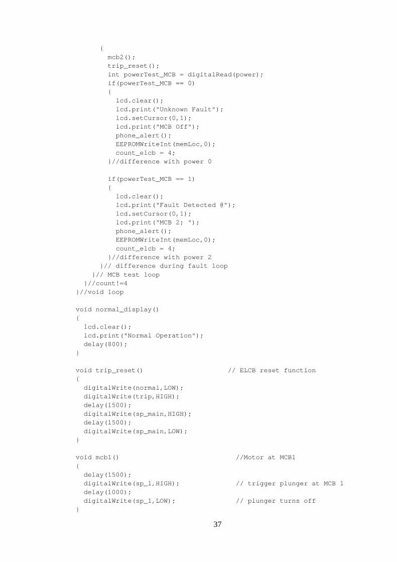
37
{ mcb2(); trip_reset(); int powerTest_MCB = digitalRead(power); if(powerTest_MCB == 0) { lcd.clear(); lcd.print("Unknown Fault"); lcd.setCursor(0,1); lcd.print("MCB Off"); phone_alert(); EEPROMWriteInt(memLoc,0); count_elcb = 4; }//difference with power 0 if(powerTest_MCB == 1) { lcd.clear(); lcd.print("Fault Detected @"); lcd.setCursor(0,1); lcd.print("MCB 2; "); phone_alert(); EEPROMWriteInt(memLoc,0); count_elcb = 4; }//difference with power 2 }// difference during fault loop }// MCB test loop }//count!=4 }//void loop void normal_display() { lcd.clear(); lcd.print("Normal Operation"); delay(800); } void trip_reset() // ELCB reset function { digitalWrite(normal,LOW); digitalWrite(trip,HIGH); delay(1500); digitalWrite(sp_main,HIGH); delay(1500); digitalWrite(sp_main,LOW); } void mcb1() //Motor at MCB1 { delay(1500); digitalWrite(sp_1,HIGH); // trigger plunger at MCB 1 delay(1000); digitalWrite(sp_1,LOW); // plunger turns off }
38
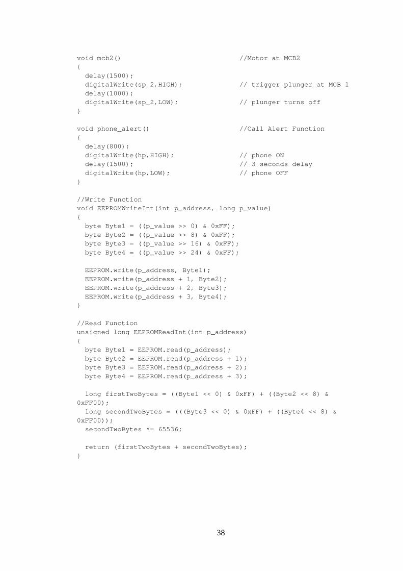
void mcb2() //Motor at MCB2 { delay(1500); digitalWrite(sp_2,HIGH); // trigger plunger at MCB 1 delay(1000); digitalWrite(sp_2,LOW); // plunger turns off } void phone_alert() //Call Alert Function { delay(800); digitalWrite(hp,HIGH); // phone ON delay(1500); // 3 seconds delay digitalWrite(hp,LOW); // phone OFF } //Write Function void EEPROMWriteInt(int p_address, long p_value) { byte Byte1 = ((p_value >> 0) & 0xFF); byte Byte2 = ((p_value >> 8) & 0xFF); byte Byte3 = ((p_value >> 16) & 0xFF); byte Byte4 = ((p_value >> 24) & 0xFF); EEPROM.write(p_address, Byte1); EEPROM.write(p_address + 1, Byte2); EEPROM.write(p_address + 2, Byte3); EEPROM.write(p_address + 3, Byte4); } //Read Function unsigned long EEPROMReadInt(int p_address) { byte Byte1 = EEPROM.read(p_address); byte Byte2 = EEPROM.read(p_address + 1); byte Byte3 = EEPROM.read(p_address + 2); byte Byte4 = EEPROM.read(p_address + 3); long firstTwoBytes = ((Byte1 << 0) & 0xFF) + ((Byte2 << 8) & 0xFF00); long secondTwoBytes = (((Byte3 << 0) & 0xFF) + ((Byte4 << 8) & 0xFF00)); secondTwoBytes *= 65536; return (firstTwoBytes + secondTwoBytes); }
39
APPENDIX C
40
APPENDIX D

41
APPENDIX E