
Autohelm - Equipment
80
Autohelm TILLER AUTOPILOT Operation and Installation
Transcript of Autohelm - Equipment

Autohelm
TILLERAUTOPILOTOperation and
Installation
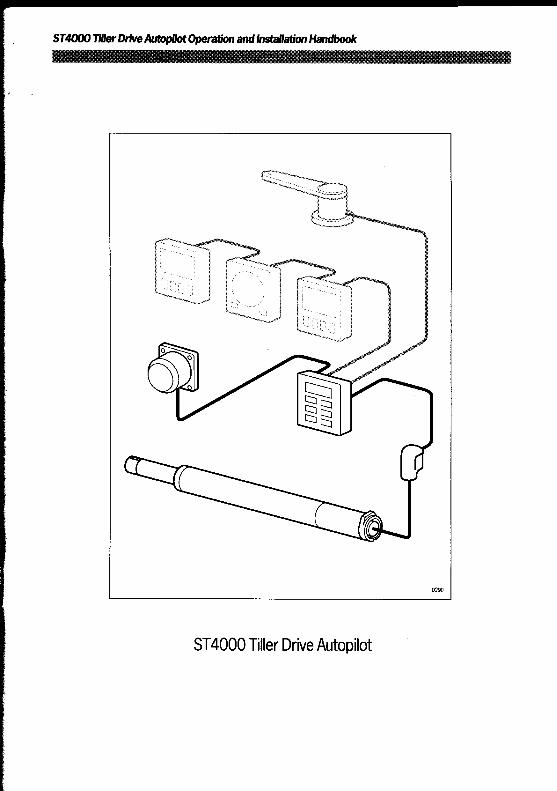
ST4000 Tiller Drive Autopilot

ContentsSpecifications 2Introduction 3Safety 4
BasicOperation
Chapter 1: Operation 7
Basic principles 71.2 Operator controls . . .......... . .............. 8
Standby 8Auto ............................ . 8Course changes (-1, +1, -10, +10) . . .. . . ...... . . .. ... ..9Dodge . . . ... .... . . . . . . . ... . . . . . ....... . . .. ... . .. 10'Track Control . . . . . . . . . . . . . . . . . . . . . . . . . . . . . . . . . . . . . . . . . . . . . . . . . . . . . . . . . . . . . . . . . . . . . . 11Windvane Mode (WindTrim) . . . . . . . . . . . . . . . . . . . . . . . . . . . . . . . . . . . . . . . . . . . . . . . . . . .11Automatic Deadband Control (Auto seastate) . . . . . . . .. . . ...12Automatic Tack (Autotack)........................... 13Illumination . . . . . . . . . . . . . . . . . . . . . . . . . . . . . . . . . . . . . . . . . . . . . . . . . . . . . . . . . . . . . . . . . . . . . . . . . . 14Off Course Alarm . . . . . . . . . . . . . . . . . . . . . . . . . . . . . . . . . . . . . . . . . . . . . . . . . . . . . . . . . . . . . . . . . 14
1 .3 Operating hints . . . . . . . . . . . . . . . . . . . . . . . . . . . . . . . . . . . . . . . . . . . . . . . . . . . . . . . . . . . . . . . . . . . 15
AdvancedOperation
Chapter 2: Wing 'Back Control' and 'WindTrim' 20Chapter 3: Adjusting autopilot performance . . . . . . . . . . . . . . . . . . . . . . . . . . . 28Chapter 4: Autopilot re-calibration . . . . . . . . . . . . . . . . . . . . . . .. . . . . . . . . . . . . . . . . . 31
Installation
Chapter 5: Installation..........................................................45Chapter 6: Interfacing to GPS, Decca, Loran, Wind 67Chapter 7: Functional Test and Initial Sea Trial .. . ..... .. ...69Chapter 8: Accessories . . . . . . . . . . . . . . . . . . . . . . . . . . . . . . . . . . . . . . . . . . . . . . . . . . . . . . . . .76Chapter 9: Maintenance 78Chapter 10 : Fault Finding .. . . . . . . . . . . . . . . . . . . . . . . . . . . . . . . . . . . . . . . . .._. . . . ..79

SafetyPassage making under autopilot can greatly increase the pleasure of thevoyage and ensure the crew can relax. However, this can lead to adangerous lack of attention to basic seamanship. The following rulesshould always be observed :-
" Maintain a permanent watch and check regularly all round for othervessels and obstacles to navigations . No matter how clear the sea mayappear a dangerous situation can develop rapidly
" Maintain an accurate record ofthe vessel's position either by use of aradio navigation receiver or visual bearings
" Maintain a continuous plot of position on a current chart. Ensure thelocked autopilot heading steers you clear of all obstacles . Make properallowance for Tidal Set -the autopilot cannot
" Even when yourautopilot is locked to the desired Track using a radionavigation receiver maintain a log and a regular positional plot. Radio
navigation signals can produce significant errors under some circurn-
stances and the autopilot cannot detect this situation
" Ensure that all members of crewarefamiliar with the proce-dures required to disengage the autopilot
" When searoom is restricted a crew member must be close to thecontrol head at all times if under autopilot control
YourAutohelm ST4000 will add a new dimension to your boating enjoy-
ment. However, it is the responsibility ofthe skipper to ensure the safety of
the vessel at all times by careful observance ofthese basic rules .
Basic Operation
ContentsChapter l: Operation . . . . . . . . . . . . . . . . . . . . . . . . . . . . . . . . . . . . . . . . . . . . . . . . . . . . . . . ..7
1 .1 Basic principles . . . . . . . . . . . . . . . . . . . . . . . . . . . . . . . . . . . . . . . . . . . . . . . . . . . . . . . . . . . . . . .71 .2 Operator controls . . . . . . . . . . . . . . . . . . . . . . . . . . . . . . . . . . . . . . . . . . . . . . . . . . . . . . . . . . . .8
Standby . . . . . . . . . . . . . . . . . . . . . . . . . . . . . . . . . . . . . . . . . . . . . . . . . . . . . . . . . . . . . . . . . . . . . . . . . . . 8Auto . . . . . . . . . . . . . . . . . . . . . . . . . . . . . . . . . . . . . . . . . . . . . . . . . . . . . . . . . . . . . . . . . . . . . . . . . . . . . . . .8Course changes (-l, +1, -10, +10) . . . . . . . . . . . . . . . . . . . . . . . . . . . . . . . . . .9Dodge . . . . . . . . . . . . . . . . . . . . . . . . . . . . . . . . . . . . . . . . . . . . . . . . . . . . . . . . . . . . . . . . . . . . . . . . . . .10'Track Control' . . . . . . . . . . . . . . . . . . . . . . . . . . . . . . . . . . . . . . . . . . . . . . . . . . . . . . . . . . . . . . .11Windvane Mode (WindTrim) . . . . . . . . . . . . . . . . . . . . . . . . . . . . . . . . . . . . . . . . . . . . .11Automatic Deadband Control (Auto seastate) . . . . . . . . . . . . . . . . . . . .12Automatic Tack (Autotack) . . . . . . . . . . . . . . . . . . . . . . . . . . . . . . . . . . . . . . . . . . . . .13Illumination . . . . . . . . . . . . . . . . . . . . . . . . . . . . . . . . . . . . . . . . . . . . . . . . . . . . . . . . . . . . . . . . . . . .14Off Course Alarm . . . . . . . . . . . . . . . . . . . . . . . . . . . . . . . . . . . . . . . . . . . . . . . . . . . . . . . . . . .14
1 .3 Operating hints . . . . . . . . . . . . . . . . . . . . . . . . . . . . . . . . . . . . . . . . . . . . . . . . . . . . . . . . . . . . . .15
Chapter 1 :Operation
Chapter 1 : Operation1.1 Basic principles
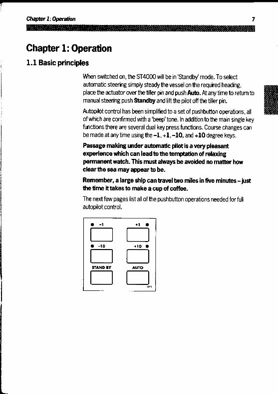
When switched on, the ST4000 will be in'Standby mode . To selectautomatic steering simply steady the vessel on the required heading,place the actuator over the tiller pin and push Auto . At anytime to return tomanual steering push Standby and lift the pilot off thetiller pin .
Autopilot control has been simplified to a setof pushbutton operations, allofwhich are confirmed with a 'beep' tone . In addition to the main single keyfunctions there are several dual key press functions . Course changes canbe made at anytime using the -1, +1, -10, and +10 degree keys .
Passage making under automatic pilot is a very pleasantexperience which can lead tothe temptation of relaxingpermanent watch. This must always be avoided no matter howclearthe seamayappear to be .
Remember, a large ship can travel two miles in five minutes -justthe time ittakes to make acup of coffee.
The nextfew pages list all of the pushbutton operations needed for fullautopilot control .

1.2 Operator controls
Standby
Push to disengage the autopilot for hand steering
The previous auto heading is memorised and can be recalled using theAuto key (see 'Auto') .In'Standby the display shows the vessels current compass heading .
Auto
Push to engage automatic steering and maintain current heading
In 'Auto' the display shows the locked autopilot heading .
If for any reason the vessel is steered away from the selected lockedheading (e .g . Dodge manoeuvre or selecting'Standby) then :
Push and hold down Auto for 1 second
The previous locked heading will be flashed for 10 seconds . To select thisheading, and resume the original course, press the Auto key oncewithin10 seconds .Also see'Dodge' - page 10 .
Chapter 1: Operation
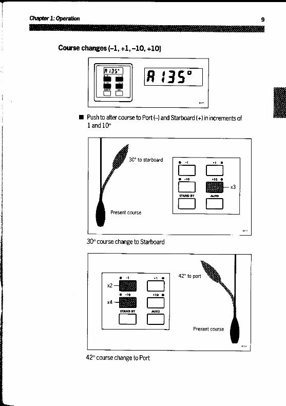
Course changes (-1, +1, -10, +10)
Push to alter course to Port (-) and Starboard (+) in increments of1 and 10°
30° to starboard
Present course
30° course change to Starboard
42° to port
Present course
42° course change to Port

DodgeIn order to avoid an obstacle under autopilot control selecta coursechange in the appropriate direction (say starboard 30° = 3x +10°) .
When safely clear of the obstacle press and hold down Auto for 1second .The previous locked heading will now be flashed on the screen . To returnto the old course press Autowithin 10 seconds .
Alternatively the previous course change can be reversed via the key padexample : 3 x-10° .
Chapter 1 : Operation
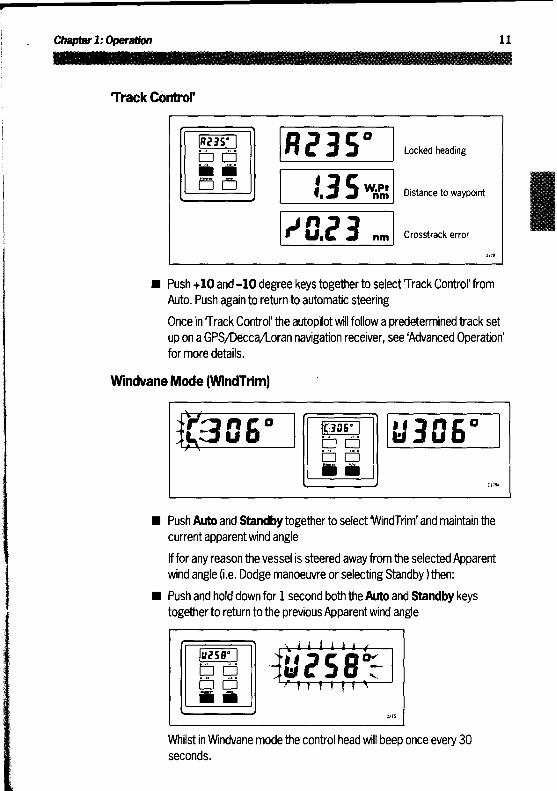
Track Control'
Locked heading
Distance to waypoint
Crosstrack error
Push +10 and -10 degree keys together to select Track Control'fromAuto . Push again to return to automatic steering
Once in Track Control' the autopilot will follow a predetermined track setup on a GPS/Decca/Loran navigation receiver, see 'Advanced Operation'for more details .
Windvane Mode (WindTrim)
Push Auto and Standby together to select 'WindTrim' and maintain thecurrent apparent wind angle
If for any reason the vessel is steered away from the selected Apparentwind angle (i .e . Dodge manoeuvre or selecting Standby) then :
Push and hold down for 1 second both the Auto and Standbykeystogether to return to the previous Apparent wind angle
Whilst in Windvane mode the control head will beep once every 30seconds .

Automatic Deadband Control (Auto seastate)
Press the +1 and -1 degree course change keys together totogglebetween auto deadband and fixed minimum deadband . The degree signwill flash whenthe fixed minimum dead band is selected
This can only be done with the Autopilot in 'Auto' mode .
'Automatic deadband' (Auto seastate) will cause the pilot to graduallyneglect repetitive movements of the vessel and only respond to truevariations in course . This provides the best compromise between powerconsumption and course keeping accuracy by neglecting unnecessaryrudder movements .
'Minimum deadband' will always provide the tightest course keepingpossible but atthe expense of increased power consumption and driveunit activity .

Chapter 1 : Operation
Automatic Tack (Autotack)
The ST4000 has a built in automatic tack facility which will turn the vesselthrough 100° in the required direction . This feature is available in bothcompass and vane modes .
Press the +1 and +10 degree keys together to Tack through 100° tostarboard
Or :
Press the-1 and -10 degree keys together to Tack through 100° to port

IlluminationIllumination forthe control head displaycan be switched on for nighttimeviewing . This can only be done with the autopilot in'Standby mode
Press the +1 and -1 keys together to toggle illumination on and off
Also if other SeaTalk instruments or autopilot control units are connectedtothe SeaTalk bus the illumination on the ST4000 can be switched on orofffrom these units .
Off Course AlarmThe off course alarm will sound if the locked autopilot heading and thevessels current heading differ, for greater than 20 seconds, by more thanthe value set in calibration level 6.
To cancel the off course alarm push Standby to return to hand steering .
If the off course alarm sounds it is usually an indication that the vessel iscarrying too much sail, orthat the sails are badly balanced . In this case asignificant improvement in course keeping can usually be obtained byimproving sail balance .
1 .3 Operating hints
It is very important to understand the effectof sudden trim changes onsteering performance. When a sudden trim change occurs, due forexample to weather helm or sail imbalance, there will be a delay before theautomatic trim applies rudder to restorethe locked heading . Thiscorrection can take upto one minute . Large course changes whichchange the apparentwind direction can produce large trim changes. Inthese casesthe autopilot will not immediately assume the new automaticheading, and will only settle onto course when the automatic Trim hasbeen fully established .To minimise the time delay the following procedure may be adopted forlarge course changes ." Note required new heading" Select Standby and steer manually" Bring vessel onto new heading" Select Auto and let vessel settle onto course" Bring to final course with 1° incrementsIt is sound seamanship to make major course changes onlywhilst steeringmanually . In this way any obstructions or other vessels may be clearedproperly and due account taken of the changed wind and sea conditionson the new heading priorto engaging the autopilot .In gusting conditions the course may tend to wander slightly, particularly inthe case of a sailing yacht with badly balanced sails . In the latter case, asignificant improvement in course keeping can always be obtained byimproving sail balance . Bear in mind the following important points:" Do not allowthe yachtto heel overexcessively" Ease the mainsheet traveller to leeward to reduce heeling and weather
helm" If necessary reef the mainsail a little earlyIt is also advisable whenever possible to avoid sailing with the wind deadastern in very strong winds and large seas.Ideally, the wind should be brought at least 30° away from a dead run andin severe conditions it may be advisable to remove the mainsail altogetherand sail under headsail only. Provided these simple precautions are takenthe autopilot will be able to maintain competent control in gale forceconditions .

Advanced
Operation

ContentsChapter 2: Using 'Track Control' and 'WindTrim'................. 20
2.1 Operation in 'Track Control' . . . . . . . . . . . . . . . . . . . . . . . . . . . . . . . . . . . . . . . . . . . . 20Operating hints . . . . . . . . . . . . . . . . . . . . . . . . . . . . . . . . . . . . . . . . . . . . . . . . . . . . . . . . . . . . . .20Cross track error . . . . . . . . . . . . . . . . . . . . . . . . . . . . . . . . . . . . . . . . . . . . . . . . . . . . . . . . . . .21Tidal Stream Compensation . . . . . . . . . . . . . . . . . . . . . . . . . . . . . . . . . . . . . . . . . . . .22Waypoint Advance . . . . . . . . . . . . . . . . . . . . . . . . . . . . . . . . . . . . . . . . . . . . . . . . . . . . . . . . . . 22Limitations . . . . . . . . . . . . . . . . . . . . . . . . . . . . . . . . . . . . . . . . . . . . . . . . . . . . . . . . . . . . . . . . . . . . .23Low Speed Operation . . . . . . . . . . . . . . . . . . . . . . . . . . . . . . . . . . . . . . . . . . . . . . . . . . . . .23Dodges . . . . . . . . . . . . . . . . . . . . . . . . . . . . . . . . . . . . . . . . . . . . . . . . . . . . . . . . . . . . . . . . . . . .24Safety . . . . . . . . . . . . . . . . . . . . . . . . . . . . . . . . . . . . . . . . . . . . . . . . . . . . . . . . . . . . . . . . . . . . . . . . . . .24Warning messages . . . . . . . . . . . . . . . . . . . . . . . . . . . . . . . . . . . . . . . . . . . . . . . . . . . . . . . . . 25
NMEA data not received . . . . . . . . . . . . . . . . . . . . . . . . . . . . . . . . . . . . . . . . . . . .25NMEA data error . . . . . . . . . . . . . . . . . . . . . . . . . . . . . . . . . . . . . . . . . . . . . . . . . . . . . . . 25Large cross track error . . . . . . . . . . . . . . . . . . . . . . . . . . . . . . . . . . . . . . . . . . . . . 25Waypoint advance . . . . . . . . . . . . . . . . . . . . . . . . . . . . . . . . . . . . . . . . . . . . . . . . . . . . . 25
2 .2 Operation in 'WindTrim' mode . . . . . . . . . . . . . . . . . . . . . . . . . . . . . . . . . . . . . . . . .26Operating hints . . . . . . . . . . . . . . . . . . . . . . . . . . . . . . . . . . . . . . . . . . . . . . . . . . . . . . . . . . . . . .26Wind shift alarm . . . . . . . . . . . . . . . . . . . . . . . . . . . . . . . . . . . . . . . . . . . . . . . . . . . . . . . . . . . . .27
Chapter 3: Adjusting autopilot performance . . . . . . . . . . . . . . . . . . . . . . 283.1 Setting up Rudder Gain . . . . . . . . . . . . . . . . . . . . . . . . . . . . . . . . . . . . . . . . . . . . . . . . . .283.2 Setting up Automatic Trim . . . . . . . . . . . . . . . . . . . . . . . . . . . . . . . . . . . . . . . . . . . . . .30
Chapter 4: Autopilot re-calibration . . . . . . . . . . . . . . . . . . . . . . . . . . . . . . . . . . . . 314.1 Entering calibration mode . . . . . . . . . . . . . . . . . . . . . . . . . . . . . . . . . . . . . . . . . . . . . . . 314.2 Exiting calibration mode . . . . . . . . . . . . . . . . . . . . . . . . . . . . . . . . . . . . . . . . . . . . . . . . .324.3 Suggested initial calibration settings . . . . . . . . . . . . . . . . . . . . . . . . . . . . . . .324.4 Calibrating the autopilot to suit your boat . . . . . . . . . . . . . . . . . . . . . . . . . 34
Calibration Level 1 (Rudder Gain) . . . . . . . . . . . . . . . . . . . . . . . . . . . . . . . . . . . ..34Calibration Level 2 (Rudder Offset) . . . . . . . . . . . . . . . . . . . . . . . . . . . . . . . . . . . 34Calibration Level 3 . . . . . . . . . . . . . . . . . . . . . . . . . . . . . . . . . . . . . . . . . . . . . . . . . . . . . . . ..34Calibration Level 4 (Turn Rate Limit) . . . . . . . . . . . . . . . . . . . . . . . . . . . . . . . . . 35Calibration Level 5 (Cruise Speed) . . . . . . . . . . . . . . . . . . . . . . . . . . . . . . . . . . .35Calibration Level 6 (Off course alarm angle) . . . . . . . . . . . . . . . . . . . . .35Calibration Level 7 (Trim Level) . . . . . . . . . . . . . . . . . . . . . . . . . . . . . . . . . . . . . . . . 36Calibration Level 8 (Steering system type) . . . . . . . . . . . . . . . . . . . . . . . . 37Calibration Level 9 (Magnetic variation) . . . . . . . . . . . . . . . . . . . . . . . . . . . .37Calibration Level 10 (N'ly/S'ly heading error correction) . . ..37Calibration Level 11 (Current Vessel Latitude) . . . . . . . . . . . . . . . . . . . 38Calibration Level 12 (Not available with the ST4000 . . . . . . . . 39Calibration Level 13 (Rudder Damping) . . . . . . . . . . . . . . . . . . . . . . . . . . . .39
4.5 Disabled calibration access . . . . . . . . . . . . . . . . . . . . . . . . . . . . . . . . . . . . . . . . . . . .41

Chapter 2: Using Track Control' and 'WindTrim'
Advanced operationThe ST4000 has been set-up atthe factory to provide stable performancefor most types of boat . Depending on personal choice and type of boatmanyof the functions and features available in the ST4000 can be finetuned . This is normally required if:" The pilot does not maintain a selected heading" A rudder reference transducer is fitted" The boat appears to be unstable on Northerly headings (Southerly
headings in the southern hemisphere)" You wishto display True compass headings" You operate in Track Control' mode" You wish to change the Off Course alarm angleThe ST4000 is also capable of being supervised from a Navigation systemsuch as a GPS, Decca or Loran receiver-automatically compensating fortidal streams and leeway. Courses relative to the apparent wind directioncan also be maintained if the ST4000 is connected to a wind transducer.'Advanced Operation' offers a complete guide to ST4000 calibration andcomprehensively covers operation in both Track Control' and 'WindTrim'supervisory modes . It also shows how the system can be expanded toinclude other SeaTalk products .
Chapter 2: Using Track Control' and'WindTrim'2.1 Operation in Track Control'
Track Control' allows the ST4000 to maintain track between twoway-points entered on a GPS, Decca, or Loran based Navigation system .
Operating hints
The Control head can receive cross track error data from any Navigationsystem transmitting data to the NMEA 0180 or 0183 format . The ST4000will then compute course changes which will keep your boat on a pre-determined track, automatically compensating for tidal streams andleeway .When initiating Track Control' the track can be acquired in one oftwoways :" Automatic acquisition (NMEA 0183 CrossTrack Error and Bearing toWaypoint data required from the receiver)
" Manual acquisition (NMEA 0180 or0183 Cross Track Error datarequired only)
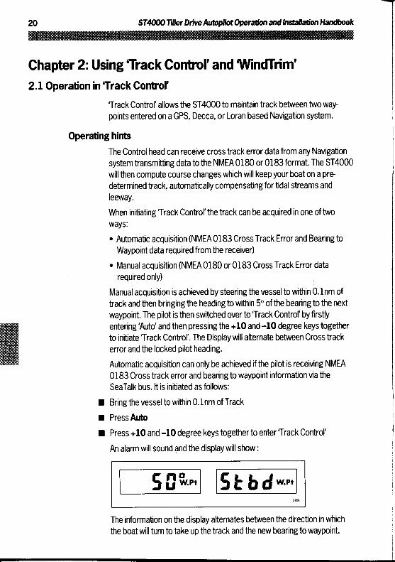
Manual acquisition is achieved by steering thevessel to within 0 .1nm oftrack and then bringing the heading to within 5° ofthe bearing to the nextwaypoint . The pilot is then switched overto Track Control' byfirstlyentering 'Auto' and then pressing the +10 and-10 degree keys togetherto initiate Track Control' . The Display will alternate between Cross trackerror and the locked pilotheading .
Automatic acquisition can only be achieved if the pilot is receiving NMEA0183 Cross track error and bearing towaypoint information via theSeaTalk bus . It is initiated as follows :
" Bring the vessel to within 0 .1 nm ofTrack
" Press Auto" Press +10 and -10 degree keys togetherto enter Track Control'
An alarm will sound and the display will show
The information on the display alternates between the direction in whichthe boat will turnto take up the track and the new bearing to waypoint .

Chapter2: Using ?rack Control' and WindMrn'
Check that it is safe to turn onto the new course .
Press the +10 and -10 degree keys togetherThe boat will now turn on to the new course and the alarm will cancel .The following navigation information will now be continuously cycled on thedisplay :
Locked heading
Distance to waypoint
Cross track error
Cross track error
Cross track error is the vessel distance from a planned route . This isdisplayed in nautical miles and is read directly from your position trans-ducer(see above).
Crosstrackerror
Waypoint 1 Waypoint 2

Tidal Stream Compensation
Tidalcomponents
Vessel speedover ground
Vessel speedthrough water
Under mostconditions Track Control' will hold the selected track to within±0.05nm (300ft) or better.
The autopilot takes account of vessel speed when computing coursechanges to ensure optimum performance over a wide range of vesselspeeds . If an Autohelm ST50 Speed or Tridata instrument is connected tothe SeaTalk bus the control head will use measuredvessel speed,otherwise the cruise speed entered during calibration level 5 will be used .
WaypointAdvanceIf your navigation receiver transmits valid 'Waypoint Number' and'Bearingto Waypoint' NMEA headers it is possible to advance from one waypointtothe next by simply pressing the -10 and +10 degree keys together.
As the vessel passes the target waypoint the navigation receiver shouldselect, manually or automatically, the next target waypoint . The ST4000will detect the newtarget waypoint number and display the newbearing towaypoint and also the direction it will turn to acquire it . This will beaccompanied by an alarm to indicate waypointarrival (see page 25) .
Chapter2: UsingTrack Control' and 'WindTrim'
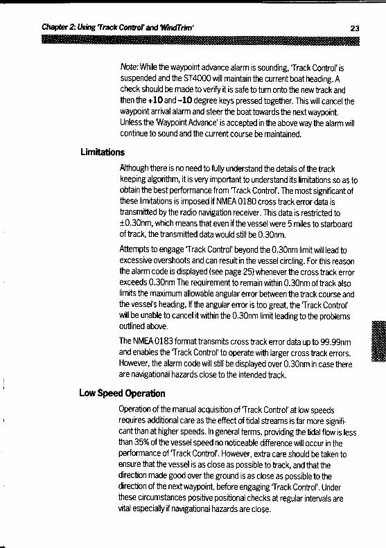
Note: While the waypoint advance alarm is sounding, Track Control' issuspended and the ST4000 will maintain the current boat heading. Acheck should be made to verify it is safeto turn onto the newtrack andthen the +10 and -10 degree keys pressed together. This will cancel thewaypoint arrival alarm and steer the boattowards the nextwaypoint .Unless the 'Waypoint Advance' is accepted in the aboveway the alarm willcontinue to sound and the current course be maintained.
LimitationsAlthough there is no need to fully understand the details of thetrackkeeping algorithm, it is very importantto understand its limitations so as toobtain the best performance from Track Control'. The most significant ofthese limitations is imposed if NMEA 0180 crosstrack error data istransmitted bythe radio navigation receiver. This data is restricted to±0.30nm, which means that even if the vessel were 5 miles to starboardof track, the transmitted data would still be 0.30nm.Attempts to engage Track Control' beyond the 0.30nm limit will lead toexcessive overshoots and can result in the vessel circling . Forthis reasonthe alarm code is displayed (see page 25)whenever the cross track errorexceeds 0.30nm The requirement to remain within 0.30nm of track alsolimits the maximum allowable angular error between the track course andthe vessel's heading . If the angular error is too great, the Track Control'will be unable to cancel it within the 0.30nm limit leading to the problemsoutlined above .The NMEA 0183 format transmits cross track error data up to 99.99nmand enables the Track Control' to operate with larger cross track errors .However, the alarm code will still be displayed over 0.30nm in case thereare navigational hazards close to the intended track.
Low Speed OperationOperation of the manual acquisition of Track Control' at low speedsrequires additional care as the effect of tidal streams is far more significant
than athigherspeeds. Ingeneral terms,providingthetidal flow is lessthan 35% of the vessel speed no noticeable difference will occur in theperformance of Track Control'. However, extra care should be taken toensure that the vessel is as close as possible to track, and that thedirection made good over the ground is as close as possible to thedirection ofthe nextwaypoint, before engaging Track Control' . Underthese circumstances positive positional checks at regular intervals arevital especially if navigational hazards are close .

Dodges
Full control remains available from the control head when the autopilot is inTrack Control' . Dodges are accomplished by simply selecting the desiredcourse change on the Autohelm keypad . Once the hazard has beenavoided the course change selected for the dodge manoeuvre should becancelled by selecting an equal course change in the opposite direction .Provided the vessel remains within 0 .1nm of track there is no need tosteer back towards the track .
Safety
Passage making in Track Control' removes the chores of compensationfor wind and tidal drift and will aid precise navigation . It is most importanthowever to maintain an accurate log with regular plots and to verify thecomputed position read from the radio navigation receiver with a deadreckoned position from recording the average course steered and thedistance logged . In open water such plots should be atleast hourly andmore frequent in confined waters or when potential hazards are near .
Local variations in radio signal quality and changes in the tidal stream willproduce deviations from the desired track . When setting up waypoints,remember that deviations will occur, and thoroughly check along eachtrack and to 0.5nm each side to ensure that there are no hazards withinthe zone . Always confirm the position given bythe position transducerusing an easily identifiable fixed object at the start of a passage to checkand enable compensation to be made for fixed positional errors .
The use of Track Control' will enable accurate track keeping evenin complex navigational situations . It cannot remove theresponsibility ofthe skipperto ensure the safety of his vessel at alltimes by careful navigation and frequent position checks .

Chapter2: Using 'Track Control' and 'WindTrim'
Warning messagesNMEA data not received
The'no data' display will be shown if Track Control' is engaged when theautopilot is not receiving either NMEA 0180 or 0183 data.
NMEA data error
The'data error' display will be shown if Track Control' is engaged whilstthe Position transducer (GPS, Loran, Decca) is receiving a low strengthsignal.This will clear as soon as the signal strength improves .
Large cross track error
The 'large cross track error' alarm sounds if the cross track error receivedbythe pilot exceeds 0.3nm .
Waypoint advance
The waypoint advance alarm sounds whenever the Radio NavigationReceiver (GPS, Loran, Decca) changes the targetwaypoint number . Whenthis occurs the pilot will continue on its current heading but flash thebearing to the next waypointon the display . This will alternate with thedirection in which the boat will turn to take up thatbearing . You shouldcheck to ensure that such a manoeuvre would be safe and, when you arereadyto make the turn, momentarily press the +10 and -10 degree keystogether. The pilot will then turn onto the new bearing and tracktowardsthe next waypoint.Note: The waypoint advance will only operate on pilots receiving NMEA0183 bearing towaypoint information .

2.2 Operation in 'WindTrim' mode
'WindTrim' mode allows the ST4000 to maintain course relative to anapparent wind angle . It uses 'WindTrim' to eliminate the effects of turbu-lence and shortterm wind variations and provide smooth precise performanceunderwindvane withminimum power consumption .̀ WindTrim'uses
the fluxgate compass as the primary heading reference, and as changesin the apparent wind angle occur the locked compass heading is adjustedto maintain the original apparent wind angle . To use 'WindTrim' theST4000 must receivewind information from one ofthe following sources :
" SeaTalk Wind instrument-connected to the ST4000 via the SeaTalkbus
" NMEA wind information connected to the rear of the Control head
" Autohelm windvane (cat no Z087) connected via the SeaTalk interfacebox (cat no Z137)
" ST7000 or ST6000 autopilot control unit (cat no Z082 and Z124)
Operating hints'WindTrim' filters the windvane output, providing optimum response for off-shore conditions where genuine shifts in wind direction occur gradually . Ingusty and unsteady inshore conditions it is best to sail a few degreesfurther offthe wind so that changes in apparentwind direction can betolerated .
It is also important to ensure thatthe amount of standing helm isminimised bycarefulsailtrimandpositioningofthemainsheettraveller.
It is recommended thatthe headsail and mainsail are reefed a little earlyratherthantoo late .

Chapter 2:Using TrackControl' and WindTrim'
Wind shift alarm
If changes in apparent wind angle adjust the original locked compassheading by more than 15° the wind change alarm will sound
The display will then alternate between the current WindTrim' heading andthe direction ofwind shift .
Push Standby and Auto together momentarily to accept the alarm andresetthe wind shift alarm datum to the current compass heading
Before doing so verifythat the new course datum does nottake the vesselinto danger.

Chapter 3: Adjusting autopilot performance3.1 Setting up Rudder Gain
Thefactory set rudder gain level will provide stable control for initial seatrials . However, vessels can vary widely in their response to the helm, andfurther adjustment to the rudder gain may improve the autopilots steeringcharacteristics.
" Steer onto a specific course
" Hold the course steadyfor 5 to 10 seconds
" Place the actuator over the tiller pin" Press Auto to engage the autopilot on the current heading
In calm conditions the boat should maintain the locked heading .
The following test will check if the rudder level is set too high or too low.
In clear water and with the autopilot in'Auto' alter course to starboard by40° by pressing the + 10 degree key four times .
Typically, atcruising speed, a course change of40° should result in acrispturn followed by an overshoot of no more than 2° to 5° . If this occursthe rudder gain is correctly adjusted .An excessively high rudder setting results in oversteer which can berecognised by distinct overshoot of morethan 5° (A) . This condition canbe corrected by reducing the rudder gain setting .

Chapter 3: Adjustingautopilotperformance
Correctruddersetting
Newheading
Ruddersettingtoo high
Newheading
Ruddersettingtoo low
Newheading

3.2 Setting up Automatic Trim
The trim level setting determinesthe rate at which the autopilot applies'Standing helm'to correct for trim changes caused by varying wind loadson the sails or superstructure . Depending on the vessels dynamic stabilityan incorrect rate oftrim application may result in poor course keeping dueto autopilot instability . The following is a guide to recommended settings .After gaining experience with the ST4000 if it is considered that a higheror lowertrim level setting will give improved steering performance thelevel may be changed in calibration and the effect evaluated . Refertochapter 4-'Autopilot re-calibration', for instructions on howto adjust theautomatic Trim setting .
TrimLevel
Boat Type Decrease Trimlevel if :
Increase Trimlevel if:
0
1 Sail - Med/HeavyDisplacement .Full keel/Transomrudder
Autopilot reactsslowly to headingchange due tochange of heelangle
2 Sail - Mod/LightDisplacement
Autopilot givesunstable coursekeeping orexcessive driveactivity with changeof heel angle
Autopilot reactsslowly to headingchange due tochange of heelangle
3 Sail - Ultra lightdisplacement
Autopiiot givesunstable coursekeeping orexcessive driveactivity with changeof heel angle
Chapter4. Autopilot re-calibration
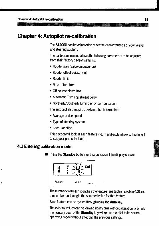
Chapter 4: Autopilot re-calibrationThe ST4000 can be adjusted to meetthe characteristics of your vesseland steering system .The calibration routine allowsthefollowing parameters to be adjustedfrom theirfactory default settings ." Rudder gain (Value on power up)" Rudder offset adjustment" Rudder limit" Rate of turn limit" Offcourse alarm limit" Automatic Trim adjustment delay" Northerly/Southerly turning error compensationThe autopilot also requires certain other information :" Average cruise speed" Type of steering system" Local variationThis section will look at each feature in-turn and explain howto finetune itto suit your particular boat .
4.1 Entering calibration mode" Press the Standby button for 5 seconds until the display shows :
The numberon the left identifies the feature (see table in section 4.3) andthe number on the right the selected value for that feature .Each feature can be cycled through using theAuto key.The existing values can be viewed at any time without alteration, a simplemomentary push ofthe Standby key will return the pilot to its normaloperating mode without affecting the previous settings .

Note : If on entering calibration the display shows :
Please refer to'Disabled calibration access'- section 4.5 for details onhowto adjust.
4.2 Exiting calibration mode
You can exit calibration at any time in one of two ways:Press Standbyfor 1 second
This will enter any adjusted values into memory .
" Momentarily press StandbyThis will exit calibration without entering any adjusted values into memory .
4.3 Suggested initial calibration settings
Listed below are suggested calibration settings . Thesewill provide safeperformance for the initial sea trial .
If you change any of the settings you can record them in the'AdjustedValues' column for future reference .
Chapter4: Autopilot re-calibration
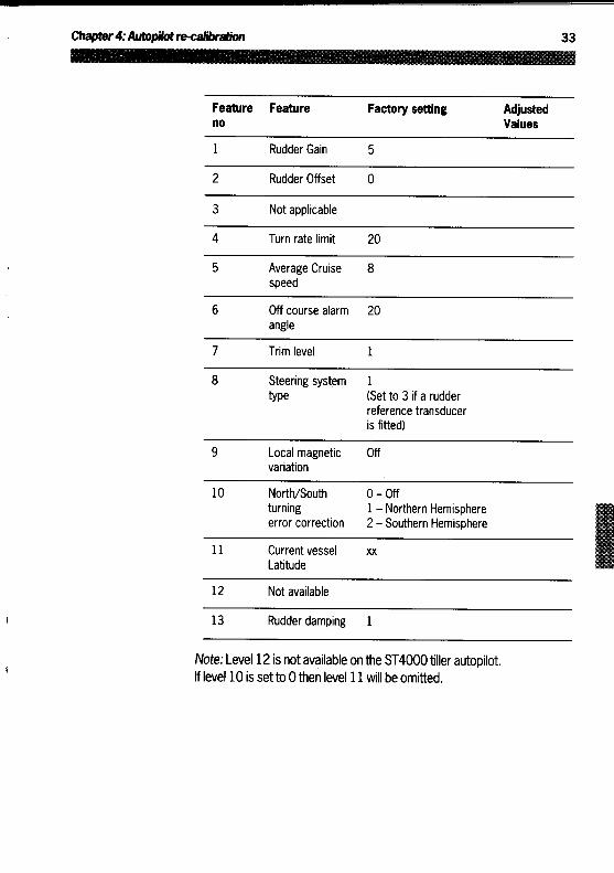
Note: Level 12 is not available on the ST4000 tiller autopilot.If level 10 is set to 0then level 11 will be omitted.
Featureno
Feature Factory setting AdjustedValues
1 Rudder Gain 5
2 Rudder Offset 0
3 Not applicable
4 Turn rate limit 20
5 Average Cruisespeed
8
6 Off course alarmangle
20
7 Trim level 1
8 Steering systemtype
1(Set to 3 if a rudderreference transduceris fitted)
9 Local magneticvariation
Off
10 North/Southturningerror correction
0 - Off1 - Northern Hemisphere2 - Southern Hemisphere
11 Current vesselLatitude
xx
12 Not available
13 Rudder damping 1

4.4 Calibrating the autopilot to suit your boat
Calibrate the pilotas follows :Enter calibration mode as described in section 4.1The display will show:
Calibration Level 1 (Rudder Gain)Calibration level 1 is Rudder gain . This requires setting up whilst underway. Please refer to Rudder gain adjustment in chapter 3.
Calibration Level2 (Rudder Offset)Calibration level 2 is'Rudder offset . This will only require setting if yourinstallation includes a rudder reference transducer .
" Press the Auto key
Manually place the helm in a central position . Use the +1 and -1 degreekeys to adjust the rudder angle reading on the right hand side ofthedisplayto zero .
Calibration Level 3Calibration level 3 does not require setting on the ST4000 linear autopilot .Press the Auto key

Chapter4: Autopilot re-calibration
Calibration Level4 (Turn Rate Limit)Calibration level 4 is Turn Rate Limit. This will limit the rate of turn ofyourvessel when under autopilot control .
" Pressthe Auto key
For sailboat applications it should be set to 20°." Set-up turn rate limit with the +1 and -1 degree buttons
Calibration Level5 (Cruise Speed)Calibration level 5 sets the boats normal cruising speed for use in TrackControl' .Press the Auto key
When interfacing with Radio navigation systems the Control head uses thevessels average cruising speed to perform track calculations .Adjust the cruise speed with the +1 and -1 degree buttons .Note : If an ST50 Speed or Tridata instrument is connected to the SeaTalkbus they will transmit boat speed information directly to the control head .
Calibration Level 6 (Off course alarm angle)Calibration level 6 is Offcourse alarm angle . This is an alarm to warn you ifthe autopilot is unable to maintain its set course .Press the Auto key

The off-course alarm operates if the autopilot strays off course by morethan the alarm angle limit for more than 20 seconds . This limit can be setin 1 ° increments anywhere between 15° and 40° using the +1 and -1degree course change buttons .
Lockedheading
Boatheading
15° max
Calibration Level 7 (Trim Level)
Calibration level 7 selects and sets the level for automatic trim . Thisapplies additional rudder to correct for weather helm.
" Press the Auto key
Trim can be setto one ofthree rates or switched off completely .
" Level 0
Trim off
" Level 1
Slowtrim correction
" Level 2
Medium trim correction
" Level 3
Fasttrim correction . (Recommended for ultra light displace-ment boats)
Adjust the trim level usingthe +1 and -1 degree buttons .
Refer to section 3.2 for further information .
Chaptera: autopilot re-calibration
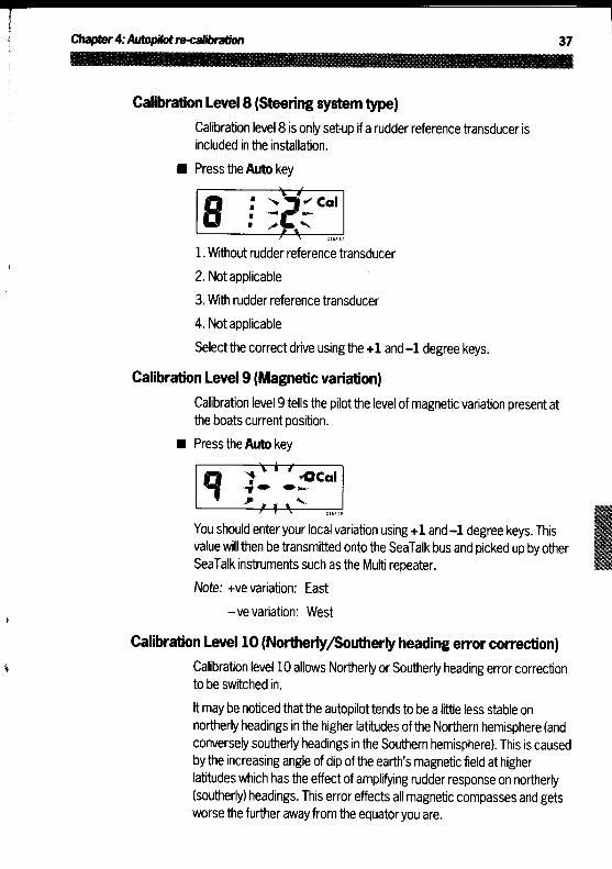
Calibration Level 8(Steering system type)Calibration level 8 is only setup if a rudder reference transducer isincluded in the installation .
" Press the Auto key
1 . Without rudder reference transducer2 . Not applicable3 . With rudder reference transducer4 . Not applicableSelect the correct drive using the +1 and -1 degree keys .
Calibration Level9 (Magnetic variation)Calibration level 9 tells the pilot the level of magnetic variation present atthe boats current position .
" Press the Auto key
You should enter your local variation using +1 and -1 degree keys . Thisvalue will then be transmitted onto the SeaTalk bus and picked up by otherSeaTalk instruments such as the Multi repeater .Note: +ve variation : East
-ve variation : West
Calibration Level 10 (Northerly/Southerly heading error correction)Calibration level 10 allows Northerly or Southerly heading error correctionto be switched in .It may be noticed that the autopilot tends to be a little less stable onnortherly headings in the higher latitudes ofthe Northern hemisphere (andconversely southerly headings in the Southern hemisphere) . This is causedby the increasing angle ofdip ofthe earth's magnetic field at higherlatitudes which hasthe effect of amplifying rudder response on northerly(southerly) headings . This error effects all magnetic compasses and getsworse the further away from the equator you are .

The ST4000 is able to compensate for this and provide precise coursekeeping on all headings by automatically adjusting the gain ofthe autopilotdepending on heading.
Pressthe Auto key
Use the +1 and -1 degree keys to select:
0=Off
1 = Northern Hemisphere
2 = Southern Hemisphere
North North
Withoutcompensation
Withcompensation
Calibration Level 11 (Current Vessel Latitude)
Calibration level 11 requires the boats current latitude (to the nearestdegree) in order to compensate for Northerly/Southerly heading error .
" Press the Auto key
Set up latitude using the -1 and +1 degree keys
Note: If the correction is set to 0 in Calibration Level 10 then level 11 will
be omitted and pressing the Auto key in Calibration Level 10 will move thedisplay directly onto level 13 (level 12 is omitted on the ST4000).

Chapter4 : Autopilot re-calibration
Calibration Level 12 (Not available with the ST4000)
This level is not available with the ST4000 Autopilot.
Calibration Level 13 (Rudder Damping)
Level 13 only requires setting up if the installation includes a rudderreference transducer and the drive 'hunts' when trying to position therudder.
" Press the Auto key
Calibration level 13 allows 1 of nine levels ofrudder damping to beselected . This should always be set to 1 initially .
Rudder damping should be set-up as follows :
Exit calibration by pressing the Standbykey for 1 second until the displayshows :
Note : A momentary push will give the same display but will not store thepreviously calibration steps .
Place the actuator over the tiller pin
Press the Auto key
Press the +10 degree course change key once
Observe the tiller movement. If the rudder appears to position and thenhunt e.g . drive port and then starboard in small jerky movements thenreturn to calibration level 13 and increase the rudderdamping level byone, using the +1 and -1 degree buttons, and repeat the test until therudder positions without hunting .
Note : It is most important that the rudder damping level is setas low aspossible for best possible course keeping .
The calibration should now be saved by pressing the Standby key for1 second.

Chapter 4 : autopilot re-calibration
4.5 Disabled calibration accessIt is possible to disable the calibration set-up to prevent unauthorisedaccess .
This is achieved as follows :
" Press and hold the-1 and Standby keys for 10 seconds until the displayshows :
Toggle the calibration access on and off usingthe -1 and +1 degree keys
Store the setting by pressing the -1 and Standby keys for 10 secondsuntil the control head returns to normal operation
If preferred this page can be removed from the handbook after accesshas been switched off.

Installation

ContentsChapter 5: Installation . . . . . . . . . . . . . . . . . . . . . . . . . . . . . . . . . . . . . . . . . . . . . . . . . . . . . .455.1 Control head . . . . . . . . . . . . . . . . . . . . . . . . . . . . . . . . . . . . . . . . . . . . . . . . . . . . . . . . . . . . . . . . .45
Siting . . . . . . . . . . . . . . . . . . . . . . . . . . . . . . . . . . . . . . . . . . . . . . . . . . . . . . . . . . . . . . . . . . . . . . . . .45Mounting procedure . . . . . . . . . . . . . . . . . . . . . . . . . . . . . . . . . . . . . . . . . . . . . . . . . . . . . . .45Cable connectors . . . . . . . . . . . . . . . . . . . . . . . . . . . . . . . . . . . . . . . . . . . . . . . . . . . . . . . . . . .46Power supply connection . . . . . . . . . . . . . . . . . . . . . . . . . . . . . . . . . . . . . . . . . . . . . . . .47Connection to the SeaTalk bus . . . . . . . . . . . . . . . . . . . . . . . . . . . . . . . . . . . . . . . .48
5.2 Fluxgate Compass . . . . . . . . . . . . . . . . . . . . . . . . . . . . . . . . . . . . . . . . . . . . . . . . . . . . . . . . .49Mounting position . . . . . . . . . . . . . . . . . . . . . . . . . . . . . . . . . . . . . . . . . . . . . . . . . . . . . . . . . . .49Cabling .
. . .. . . .
. . ..
. . . . . . . . . . . . . . . . . . . . . . . . . . . . . . . . . . . . . . . . . . . . . . 515.3 Rudder Reference Transducer . . . . . . . . . . . . . . . . . . . . . . . . . . . . . . . . . . . . . . . . 51
Mounting position . . . . . . . . . . . . . . . . . . . . . . . . . . . . . . . . . . . . . . . . . . . . . . . . . . . . . . . . . . . 51Control dimensions . . . . . . . . . . . . . . . . . . . . . . . . . . . . . . . . . . . . . . . . . . . . . . . . . . . . . . . . . 53Cabling . . . . . . . . . . . . . . . . . . . . . . . . . . . . . . . . . . . . . . . . . . . . . . . . . . . . . . . . . . . . . . . . . . . . . . . . . . 53
5.4 Linear Actuator . . . . . . . . . . . . . . . . . . . . . . . . . . . . . . . . . . . . . . . . . . . . . . . . . . . . . . . . . . . . . . 54Porthand mounting . . . . . . . . . . . . . . . . . . . . . . . . . . . . . . . . . . . . . . . . . . . . . . . . . . . . . . . ..55Basic installation . . . . . . . . . . . . . . . . . . . . . . . . . . . . . . . . . . . . . . . . . . . . . . . . . . . . . . . . . . . . 56
Tiller pin installation (cat no D001) . . . . . . . . . . . . . . . . . . . . . . . . . . . . .56Mounting socket installation (cat no D002) . . . . . . . . . . . . . . . . . . 56
Installation accessories . . . . . . . . . . . . . . . . . . . . . . . . . . . . . . . . . . . . . . . . . . . . . . . . . . . 57Pushrod extensions . . . . . . . . . . . . . . . . . . . . . . . . . . . . . . . . . . . . . . . . . . . . . . . . . . . 57Tiller brackets . . . . . . . . . . . . . . . . . . . . . . . . . . . . . . . . . . . . . . . . . . . . . . . . . . . . . . . . . .58Cantilever mounting . . . . . . . . . . . . . . . . . . . . . . . . . . . . . . . . . . . . . . . . . . . . . . . . . .60
Pedestal socket mounting . . . . . . . . . . . . . . . . . . . . . . . . . . . . . . . . . . . . . . . . . . . . . . . 62Tiller pins . .
. .. . . . . . .
. .. . . . . . . . . . . . . . . . . . . . . . . . . . . . . . . . . . . . . . . . .64Cabling and Socket Installation . . . . . . . . . . . . . . . . . . . . . . . . . . . . . . . . . . . . . . . .64
Cabling . . . . . . . . . . . . . . . . . . . . . . . . . . . . . . . . . . . . . . . . . . . . . . . . . . . . . . . . . . . . . . . . . . . .64Socket Installation . . . . . . . . . . . . . . . . . . . . . . . . . . . . . . . . . . . . . . . . . . . . . . . . . . . . . 65
Chapter 6: Interfacing to GPS, Decca, Loran, Wind . . . . . . . . . ..676.1 Cabling . . . . . . . . . . . . . . . . . . . . . . . . . . . . . . . . . . . . . . . . . . . . . . . . . . . . . . . . . . . . . . . . . . . . . .676.2 NMEA data transmission to other equipment . . . . . . . . . . . . . . . . . . . . 676.3 Data formats . . . . . . . . . . . . . . . . . . . . . . . . . . . . . . . . . . . . . . . . . . . . . . . . . . . . . . . . . . . . . . . . . 68
Chapter 7 : Functional Test and Initial Sea Trial .. . . . . . . . . . . . . . . .697.1 Functional test . . . . . . . . . . . . . . . . . . . . . . . . . . . . . . . . . . . . . . . . . . . . . . . . . . . . . . . . . . . . . . .69
Switch on . . . . . . . . . . . . . . . . . . . . . . . . . . . . . . . . . . . . . . . . . . . . . . . . . . . . . . . . . . . . . . . . . . . . . .69Operating sense . . . . . . . . . . . . . . . . . . . . . . . . . . . . . . . . . . . . . . . . . . . . . . . . . . . . . . . . . . . . . 69Rudder reference phase . . . . . . . . . . . . . . . . . . . . . . . . . . . . . . . . . . . . . . . . . . . . . . . . . 70Navigation interface (GPS, Decca, Loran) . . . . . . . . . . . . . . . . . . . . . . . . . 70Wind transducer interface . . . . . . . . . . . . . . . . . . . . . . . . . . . . . . . . . . . . . . . . . . . . . . . 71SeaTalk bus . . . . . . . . . . . . . . . . . . . . . . . . . . . . . . . . . . . . . . . . . . . . . . . . . . . . . . . . . . . . . . . . . . . 72
7.2 Initial Sea trial . . . . . . . . . . . . . . . . . . . . . . . . . . . . . . . . . . . . . . . . . . . . . . . . . . . . . . . . . . . . . . ..72Automatic Compass deviation correction . . . . . . . . . . . . . . . . . . . . . . . . . 73Autopilot operation . . . . . . . . . . . . . . . . . . . . . . . . . . . . . . . . . . . . . . . . . . . . . . . . . . . . . . . . . 74
Chapter 8: Accessories . . . . . . . . . . . . . . . . . . . . . . . . . . . . . . . . . . . . . . . . . . . . . . . . . . ..76Chapter 9: Maintenance . . . . . . . . . . . . . . . . . . . . . . . . . . . . . . . . . . . . . . . . . . . . . . . . . . . 78
Control head . . . . . . . . . . . . . . . . . . . . . . . . . . . . . . . . . . . . . . . . . . . . . . . . . . . . . . . . . . . . . . . . . . 78Drive unit . . . . . . . . . . . . . . . . . . . . . . . . . . . . . . . . . . . . . . . . . . . . . . . . . . . . . . . . . . . . . . . . . . . . . . . 78Cabling . . . . . . . . . . . . . . . . . . . . . . . . . . . . . . . . . . . . . . . . . . . . . . . . . . . . . . . . . . . . . . . . . . . . . . . . . . 78
Chapter 10 : Fault Finding . . . . . . . . . . . . . . . . . . . . . . . . . . . . . . . . . . . . . . . . . . . . . . . . . 79

Chapter 5: Installation
Chapter 5: Installation5.1 Control head
SitingThe ST4000 control head is totally waterproof and should be sited where :" It can easily be reached from the steering position" Protected from physical damage" Atleast 230mm (9in) from a compass" At least 500mm (20in) from radio receiving equipment
" Accessible from behind to secure and run cablesNote : The back cover is designed to breath through the cable boss toprevent moisture accumulation . This must be protected from the weatherbyfollowing the Mounting procedure .
Mounting procedureThe surface must be smooth and flat ." Use the template provided to mark the centers of the two fixing holes
and cable bossNote: Adjacent Control heads and ST50 instruments should have6mm (0.25in) separation to allow room for the protective covers ." Drill to 4mm (0.16in) diameter" Use a 70mm (2.75in) diameter cutter to drill the hole for the center
boss (1)
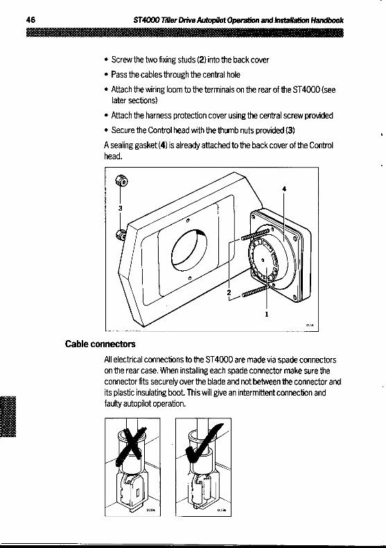
" Screw the two fixing studs (2) into the back cover" Passthe cables through the central hole" Attach the wiring loom to the terminals on the rear of the ST4000 (see
later sections)" Attach the harness protection cover using the central screw provided" Secure the Control head with the thumb nuts provided (3)A sealing gasket (4) is already attached to the back cover of the Controlhead .
Cable connectorsAll electrical connections to the ST4000 are made via spade connectorson the rear case . When installing each spade connector make sure theconnectorfits securely over the blade and not between the connector andits plastic insulating boot. This will give an intermittent connection andfaulty autopilot operation .

Chapter5 : Installation
Power supplyconnectionThe ST4000 requires its own dedicated power supply as it cannot sourcepower from the SeaTalk bus . A 2m (6.5ft) power lead is supplied for thispurpose and isterminated with 1/4in spade connectors . A 12A circuitbreaker or fuse should befitted as shown below .
Brown
Blue
12A circuit breaker or fuse
The lead can be extended if required . The following table shows theminimum cable sizes acceptable:
Cable length Copper area AWG
Up to 2.5m (8ft) 1 .5mm2 16
Up to 4.0m (13ft) 2.5mm2 14

Important!
Correct cable size is critical for correct autopilot operation .
The cable you choose may meet the required current specification but, iftoo small, will drop voltage between the supply and the control head. Thiswill reducethe power ofthe actuator .
Connection to the SeaTalkbusThe ST4000 is supplied with one SeaTalk cable tail. This can be con-nected to the spade connectors marked 'SeaTalk' on the rear oftheControl head as shown below:
Yellow(data)
Screen(ground)
Other SeaTalk instruments can now be connected to the control headusing a SeaTalk extension cable (see chapter 8-'Accessories') .

Chapter5. Installation
Yellow(data)
Screen(ground)
5AFuse/Breaker
12AFuse/
Breaker
For safety reasons the ST4000 should not supplypower to the SeaTalkbus . Any SeaTalk instruments fitted must be powered via a separate 5Afuse/breaker as shown using the power lead supplied with the instru-ments .
5.2 Fluxgate Compass
Mounting positionThe fluxgate compass should be attached to a convenient vertical surfaceusing the selftapping screws provided . There is no need to orient thefluxgate compass fore and aft . Heading alignment is carried outelectronically.
Vertical

Correct positioning of the fluxgate is crucial if ultimate performance fromthe autopilot is to be achieved . The fluxgate should ideally be positioned asnear as possible to the pitch and roll centre ofthe vessel in order tominimise gimbal disturbance .
It is very important to ensure that the fluxgate is positioned at least 0.8m(2 .5ft) away from the vessel's steering compass in order to avoid deviationof both compasses . The fluxgate must also be positioned as far away aspossible from large iron masses, such as the engine and other magneticdeviceswhich may cause deviation and reduce the sensitivity of thesensor . If any doubtexists over magnetic suitability of the chosen site, theposition may be surveyed using a simple hand bearing compass . The handbearing compass should be fixed in the chosen position and the vesselswungthrough 360° . Relative differences in reading between the handbearing compass and the vessel's main steering compass should ideallynot exceed 20° on any heading .
Chapter 5. Installation
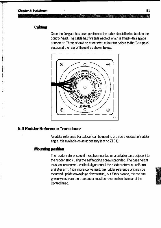
Cabling
Once the fluxgate has been positioned the cable should be led backto thecontrol head . The cable has five tails each of which is fitted with a spadeconnecter. These should be connected colour for colour to the'Compass'section at the rear of the unit as shown below :
5.3 Rudder Reference Transducer
A rudder reference transducercan be used to provide a readout of rudderangle . It is available as an accessory(cat no Z131) .
Mounting position
The rudder reference unit must be mounted on a suitable base adjacenttothe rudder stock using the self tapping screws provided . The base heightmust ensure correct vertical alignment ofthe rudder reference unit armand tillerarm . If it is more convenient, the rudder reference unit may bemounted upside down (logo downwards), but if this is done, the red andgreen wires from the transducer must be reversed on the rear oftheControl head .
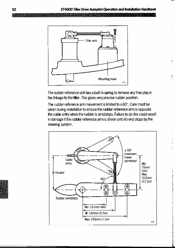
Tiller arm
Mounting base
The rudder reference unit has a built in spring to remove any free play inthe linkage to the tiller . This gives very precise rudder position .
The rudder reference arm movement is limited to ±60° . Care mustbetaken during installation to ensure the rudder reference arm is oppositethe cable entry when the rudder is amidships . Failure to do this could resultin damage if the rudder reference arm is driven onto its end stops bythesteering system .
Cableentry
± 60°maximumtravelpermitted
Parallel
Min75mm(3in)Max310mm(12.2in)
Rudder amidships
Min 101mm (4in)
'A' 140mm (5 .5in)
Max 190mm (7 .5in)

Chapter5: Installation
Control dimensionsft is important to ensure that the dimensions set out below are within thelimits set and the tiller arm and rudder reference arm are parallel to eachother .With the rudder amidships, the rudder reference arm should be oppositethe cable entry and at 90° to the connecting bar . Minor adjustment can bemade by slackening offthe 3 securing screws and rotating the transducerbody .
The tiller pin must be positioned within the limits shown . Ideally dimension'A' should be 140mm (5.5in) . However, changing this within the limitsshown will not degrade the autopilot performance but will slightly alter thescaling of the rudder angle display . The tiller pin is secured to the tiller armusing the self tapping screws provided .Cutthe studding to length and screw on the lock nuts and ball pin sockets.The sockets can then be pressed onto the pins . Move the rudder from sideto side to ensure the linkage is free from any obstruction at all rudderangles .
CablingOnce the rudder reference has been positioned the cable should be ledback to the Control head . The cable has four tails each ofwhich is fittedwith a spade connecter . These should be connected colour for colour tothe'RUDDER' connections at the rear of the Control head as shown below :
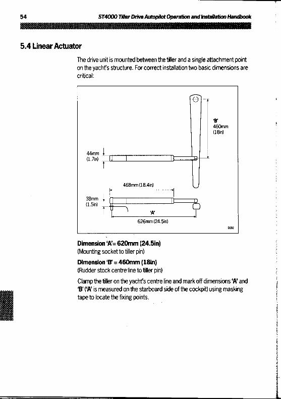
5.4 Linear Actuator
The drive unit is mounted between the tiller and a single attachment pointon the yachts structure . For correct installation two basic dimensions arecritical :
460mmMin)
44mm(1 .7in)
468mm(18.4in)
38mm(1 .5in)
'A'
626mm (24.5in)
Dimension 'A' = 620mm (24.5in)(Mounting socket to tiller pin)
Dimension'B' = 460mm (18in)(Rudder stock centreline to tiller pin)
Clamp the tiller on the yachts centre line and mark off dimensions Wand'B' ('A' is measured on the starboard side of the cockpit) using maskingtape to locate the fixing points .
Chapter5: Installation
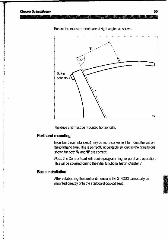
Ensure the measurements are at right angles as shown .
Sloping
rudderstock
The drive unit must be mounted horizontally.
Porthand mounting
In certain circumstances it may be more convenient to mountthe unit onthe porthand side . This is perfectly acceptable so long as the dimensionsshown for both 'A' and 'B' are correct .
Note : The Control head will require programming for port hand operation .This will be covered during the initial functional test in chapter 7 .
Basic installation
After establishing the control dimensions the ST4000 can usually bemounted directly onto the starboard cockpit seat.

Mounting socket Tiller On
Proceed as follows:
Tillerpin installation (catno D001)
" Drill 6mm (1/4in) hole x 25mm (1 in) deep at point marked .
" Using a two part epoxy such as araldite, epoxythe tiller pin into place
" Position the shoulder of the pin 12.5mm (1/2in) above the tiller surface
Mounting socket installation (catno D002)
" Drill 12.5mm (1/2in) hole x 25mm (1 in) deep into the starboard cockpitseat
" If the structure thickness at the mounting position is lessthan 25mm(1 in) carefully reinforce the under surface with a plywood plate bondedinto position
" Install the mounting socket using two partepoxy adhesive
Note: The autopilot is capable ofgenerating high pushrod loads ensurethat :
" The epoxy is allowed to harden thoroughly before applying any loads
" All holes are drilled to correct size and where necessary reinforcing is

Chapter5: Installation
provided
Installation accessoriesIf it is not possible to install the drive unit directly onto the cockpit seat ortiller as described, one of the following accessories (or combination) willensure a perfect installation .
Pushrod extensions
The pushrod length may be simply extended using one ofthe standardpushrod extensions .
Dimension `C is modified as follows :

Tillerbrackets
Where the height of the tiller above or below the cockpit seat or mountingplane is such that standard mounting is not practical a range of tillerbrackets allows the tiller pin offsetto be varied .
" Position the tiller bracketon the centre line (upper/lower) ofthe tiller andestablish control dimensions 'A' and'W .
" Mark offthe position ofthe centres of the two fixing bolt holes
" Drilltwo 6mm (0.25in) diameter clearance holesthrough the centre lineofthe tiller
" Install the tiller bracket using 2 x 6mm (0.25in) diameter bolts, nuts andwashers
" Bond the fixing bolts in place with epoxy adhesive and fully tighten thenuts
Dimension C Pushrod ExtensionLength L
Cat No
622mm (24 .5in) std dimension -
648mm (25 .5in) 25mm (l in) D003
673mm (26 .5in) 51mm (2in) D004
699mm (27 .5in) 76mm (3in) D005
724mm (28 .5in) 102mm Kin) D006
749mm (29 .5in) 107mm (5in) D007
775mm (30 .5in) 152mm (6in) D008
Dimension D(bellow tiller)
Dimension E(above tiller)
Cat No
25mm (1 in) 51mm (2in) D009
51mm (2in) 76mm (3in) D010
76mm (3in) 102mm Kin) D01 l
102mm Kin) 127mm (5in) D012
127mm (5in) 152mm (6in) D013

Chapter 5: Installation
Slopingtiller
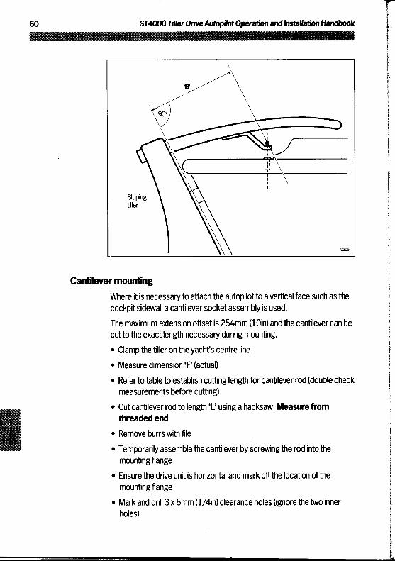
Cantilever mountingWhere it is necessary to attach the autopilot to a vertical face such as thecockpit sidewall a cantilever socket assembly is used .
The maximum extension offset is 254mm (loin) and the cantilever can becut tothe exact length necessary during mounting." Clamp the tiller on the yacht's centre line" Measure dimension 'P (actual)
" Refer to table to establish cutting length for cantilever rod (double checkmeasurements before cutting) .
" Cutcantilever rod to length 'L' using a hacksaw . Measure fromthreaded end
" Remove burrs with file" Temporarily assemblethe cantilever by screwing the rod into themounting flange
" Ensure the drive unit is horizontal and mark off the location of themounting flange
" Mark and drill 3 x 6mm (1/4in) clearance holes (ignore the two innerholes)

Chapter 5 : Installation
Dimension F Cut length L
686mm (27in) 51mm (tin)
711 mm (28in) 75mm (3in)
737mm (29in) 102mm (4in)
762mm (30in) 127mm (sin)
787mm (31 in) 152mm (6in)
813mm (32in) 178mm (7in)
838mm (33in) 203mm (8in)
" Mountthe flange using 3 x 6mm (1/4in) diameter bolts with nuts andwashers. Be sure to install the backing plate correctly, bed the flange ona thin coat of silicone sealant.
" Screw the rod firmly into place using a tommy bar
" Roughen the end ofthe rod and the inside of the cap to provide a key
" Apply the two part epoxy adhesive provided tothe rod end and cap andplace the cap overthe rod end
" Ensure the hole forthe drive unit mounting pin is facing up
" Allow the epoxy adhesive 30 minutes to fully harden before applying anyload
When the Autohelm is not in use the complete rod assembly may beunscrewed, leavingthe cockpit unobstructed .
Pedestal socket mounting
It may be necessary to raise the height of the drive unit mounting socketabove the mounting surface, for this a pedestal socket assembly is used .
" Lockthe tiller on the yacht's centre line
" Establish the standard control dimensions 'A' and'B'
" Measure dimension 'G' ensuring the autohelm actuator is horizontal
" Select the appropriate pedestal socket assembly fromthetable shown
Installation
" Mark offthe position ofthe mounting flange on the cockpit seat orcounter
" Ensure that control dimensions 'A' and 'B' are correct
" Mark and drill 3 x 6mm (1/4in) diameter clearance holes(ignore the twoinner holes)
" Mountthe flange using 3 x 6mm (1/4in) diameter bolts, nuts andwashers, being sure the back plate is installed correctly. Bed the flangeon a thin coat of silicone rubber sealant.
" Screwthe mounting socket firmly into place

Chapter5: Installation
When the Autohelm is not in use the mounting socket may be unscrewedto leave the cockpit unobstructed .
Dimension G
Pedestal socket length L
Cat No
38mm (1 .5in)
std dimension-
76mm (3in)
38mm (1.5in)
D026
89mm (3 .5in)
50mm (2in)
D027
102mm Kin)
64mm (2.5in)
D028
114mm (4 .5in)
76mm (3in)
D029
127mm (5in)
89mm (3.5in)
D030
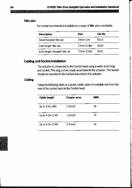
Tillerpins
For certain non-standard installations a range of tiller pins is available .
Cabling and Socket InstallationThe actuator is connected to the Control head using a water proof plugand socket . The plug comes ready assembled to the actuator. The socketshould be mounted in the cockpit area next to the actuator .
Cabling
Usingthe following table as a guide, route cable of a suitable size from therear of the socket back tothe Control head .
Description Size Cat No
Small threaded tiller pin 25mm (l in) D014
Extra length tiller pin 27mm (2 .8in) D020
Extra length threaded tiller pin 72mm (2 .8in) D021
Cable length Copper area AWG
Up to 2.5m (8ft) 1 .0mm2 18
Up to 4.0m (13ft) 1 .5mm2 16
Up to 6.5m (22ft) 2.5mm2 14

Chapter5: Installation
Using a suitable tool, crimp the spade receptacles supplied to the cablesand connect, colour for colour, to the 'drive' connections on the rear of theControl head .
Socket installation
The socket is assembled as follows :
" Fix the self adhesive template onto the bulkhead atthe selected socketlocation
" Carefully drill the 18mm (23/32in) clearance hole and 2.4mm (3/32in)pilot holes . Remove the template
" Fit the plug cap (1) to the socket body (2) as shown
" Locate the 'O' ring seal (3) into the groove between the plug cap andsocket body

Thread the cable throughthe bulkhead hole and wire into the socket asshown making sure the wires are connected tothe correct pin
Drive(Brown)
Drive(Blue)
PinIdentifi-cationStripes
ToControlhead
Attach the socket to the bulkhead using the two self tapping screwssuppliedRestrain cables as shown
Chapter6: Interfacing to GPS, Decca, Loran, MW
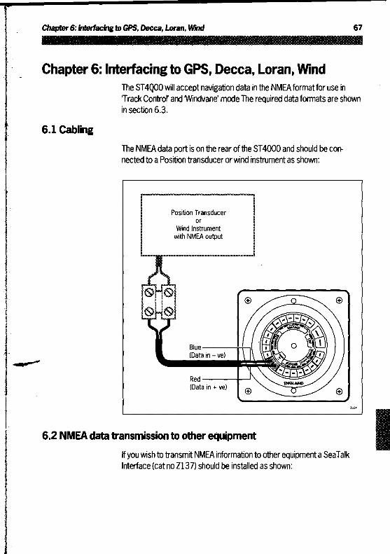
Chapter 6: Interfacing to GPS, Decca, Loran, WindThe ST4000 will accept navigation data in the NMEAformatfor use inTrack Control' and 'Windvane' mode The required data formats are shownin section 6.3 .
6.1 CablingThe NMEA data port is on the rear ofthe ST4000 and should be con-nected to a Position transducer or wind instrument as shown :
Position Transduceror
Wind Instrumentwith NMEA output
Blue(Data in - ve)
Red(Data in + ve)
6.2 NMEA data transmission to other equipmentIf you wish to transmit NMEA information to other equipment a SeaTalkInterface (cat no Z137) should be installed as shown:

Position Transducer
Radar
NMEA
SeaTalk Interface
6.3 Data formats
The following NMEA 0183 wind and navigation data can be decoded bythe ST4000 .
NMEA0180 cross track error information is also acceptable for operationin Track Control'. However, as waypointdistance, bearing and number arenottransmitted these cannot be displayed .
Data NMEA 0183
Latitude and Longitude GLL,RMC,RMA,IMA,GLP,GOP,GXP,GDP,GLF,GOF,GXF,GDF,GGA,GLA,GOAGXA,GDA
Course over the ground VTG,VTA,RMC,RMA
Speed over the ground VTG,VTA,RMC,RMA
Cross Track Error APB,APA,RMB,XTE,XTR
Bearing to Waypoint APB,BPI,BWR,BWC,BER,BEC,RMB
Distance to Waypoint WDR,WDC,BPI,BWR,BWC,BER,BEC,RMB
Waypoint Number APB,APA,BPI,BWR,WDR,BWC,WDC,RMB,BOD,WCV,BER,BEC
Wind heading / Speed VWR
Variation HVM,RMC,RMA,HVD
Chapter 7: Functional Test and Initial Sea Trial
Chapter 7: Functional Test and Initial Sea TrialThis section of the handbook consists of a set of simple tests followed by ashort sea trial . This will confirm that the system is wired correctly and isalso set-up to suityour type of boat.
7.1 Functional test
Switch on
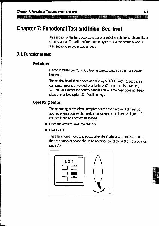
Having installed your ST4000 tiller autopilot, switch on the main powerbreaker .
The control head should beep and display ST4000. Within 2 seconds acompass heading preceded bya flashing'C' should be displayed e.g .V234. This shows the control head is active . If the head does not beepplease referto chapter 10 -'Fault finding' .
Operating sense
The operating sense of the autopilot defines the direction helm will beapplied when a course change button is pressed orthe vessel goes offcourse . It can be checked as follows :
" Placethe actuator overthe tiller pin
" Press +10°
The tiller should move to produce a turn to Starboard . If it moves to portthen the autopilot phase should be reversed by following the procedure onpage 75 .

Rudder reference phase
This should only be carried out if a rudder reference transducer is fitted .
Enter calibration mode as described in chapter4 and adjust calibrationlevel 8 (Steering system type) to 3 . Store calibration bypressing theStandby key for 1 second .
Check the rudder reference cabling and phase as follows :
" Press +1 degree and-1 degree buttons together for 1 second
The display will now indicate rudder angle .
" Movethe helm to its center position .
The display should now indicate within ± 7° . If this is not the casethentherudder reference mounting bolts should be slackened and the baserotated until it does . Final adjustmentto accurately set up the display andhelm is carried out in the'autopilot calibration' section of this handbook .
" Turn the helm to produce a turn to starboard
The rudder angle display should increase in a positive direction .
If instead it increases in a negative direction reverse the rudder referencegreen and red wires on the rear of the Control head and re-check theabove test .
Navigation interface (GPS, Decca, Loran)
If the ST4000 is interfaced to a position transducer, via its NMEA dataport, then the position transducer must be set up to transmit data asdetailed in section 6.3 .
The interface can be simply checked as follows :
" Set up a Track on the position transducer to give a cross track error ofbetween 0 and 0.3nm
" Enter 'Auto' mode by pressing the Auto key
" Enter Track' mode by pressing +10 and -10 degree keys together
After 3 seconds the pilot should automatically scroll through threenavigation displays :

Chapter 7: FunctionalTestandNOWSea Trial
If instead it shows one ofthe following error displays then there is either awiring error orthe position transducer is not set-up totransmit the requireddata format:
This display indicates data is not being received . The most likely reasonbeing a cabling error-either open circuit, shortcircuit orwires reversed.
This indicates that the signals being received by the position transducerare too weak for reliable navigation . Reference should be made to theposition transducer handbook for further action .
Wind transducer interface
If the ST4000 is connected to a wind instrumentvia its NMEA data port(not SeaTalk)then the link between the two instruments should be checkedasfollows :
" Press the Standby and Auto keys togetherThe ST4000 should then display the locked heading preceded by a 'W' asshown .
If the display continues to show the current heading preceded with aflashing 'C' then wind data is not being received by the ST4000.
The mostlikely reason being a cabling error-either open circuit, shortcircuit or wires reversed .

SeaTalk busIf the ST4000 has been linked to other SeaTalk instruments via theSeaTalk bus the link can bechecked as follows:
" Push Standby on the autopilot Control head
" Select display illumination level 3 on any other SeaTalk instrumentorautopilot control unit
The ST4000 should immediately respond by switching on its displayillumination .
If the illumination does not switch on then a cabling fault exists in theSeaTalk cabling between the ST4000 control head and the instruments/control unit.
7.2 Initial Sea trial
Having checked that the system is functioning correctly a short sea trial isnow required to completethe setting up . This should be carried outin calmwaters clear of any obstructions .
The ST4000 has a built-in calibration capability which enables it to be finetuned to suitthe individual vessel, its steering system and dynamicsteering characteristics . As supplied from the factorythe unit is calibratedto provide safe stable autopilot control forthe majority ofvessels (seesection 4.3) .
Before carrying outthe first sail trial it is recommended that the calibrationlevels be checked and if necessary reset to the recommended levels .
This procedure will only take a minute or so and full details are given inchapter 4 .
" Do not attemptto make any permanent changeto the recommendedcalibration values until a sail trial has been carried out
Chapter7: Functional Testand Initial Sea Trial
" It is importantthat the initial sail trial is carried out in conditions of lightwind and calm water so that autopilot performance can be assessedwithout the influence of strongwinds or large waves
Note:At any time during the sea trial you can lift the actuator offthe tillerpin to return to hand steering .
AutomaticCompass deviation correction
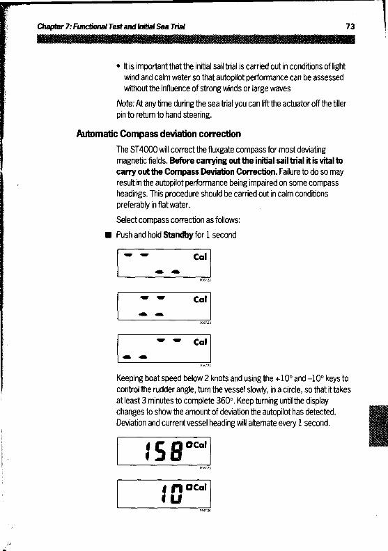
The ST4000 will correct the fluxgate compass for most deviatingmagnetic fields. Before carrying outthe initial sail trial it is vital tocarry out the Compass Deviation Correction. Failure to do so mayresult in the autopilot performance being impaired on some compassheadings . This procedure should be carried out in calm conditionspreferably in flat water.
Select compass correction as follows :
" Push and hold Standbyfor 1 second
Keeping boat speed below 2 knots and using the +10° and -10° keys tocontrol the rudder angle, turn the vessel slowly, in a circle, so that it takesat least 3 minutes to complete 360° . Keep turning until the displaychangesto show the amount of deviation the autopilot has detected .Deviation and currentvessel heading will alternate every 1 second .
Note: If the amount of deviation exceeds 15°, it is recommended thefluxgate is re-sited .
Use the +1° and -1° course change keysto increase or decrease thedisplayed heading until it agrees with the ships steering compass or aknown transit bearing .
Exitcompass adjust and store the compass correction/alignment asfollows :
Push and hold Standby for 1 second
or, to exit compass adjust without saving any new settings
" Push Standby momentarily
Autopilot operation
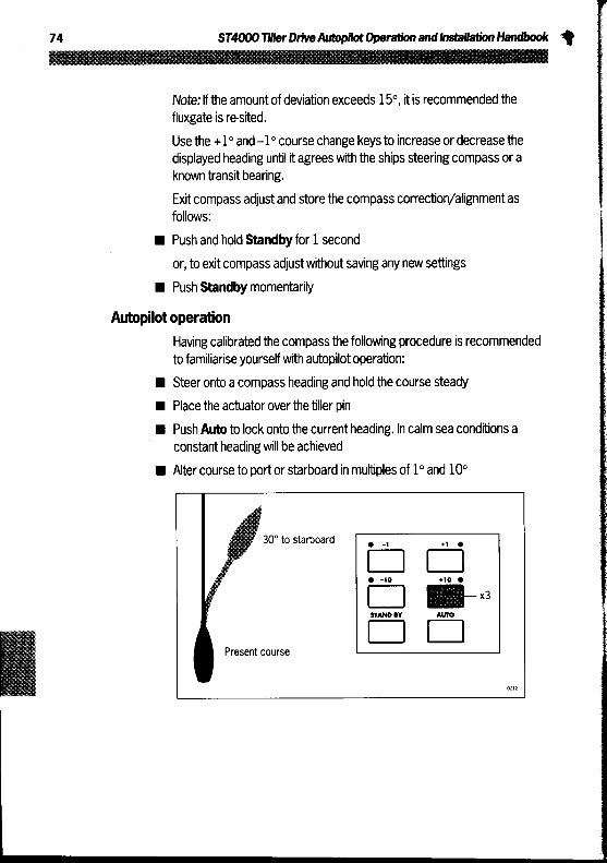
Having calibrated the compass the following procedure is recommendedto familiarise yourself with autopilotoperation:
" Steer onto a compass heading and hold the course steady
" Place the actuator over the tiller pin
" Push Auto to lock onto the current heading . In calm sea conditions aconstant headingwill be achieved
" Alter courseto port or starboard in multiples of 1° and 10°
30° to starboard
Present course

Chapter7: Functional Testand Initial Sea Trial
42° to port
Present course
Push Standby and lift the actuator from the tiller pin to return to handsteering
Operating sense reversalThe operating sense of the Autopilot can be reversed as follows :
" Press the +1 and -1 keys together for 5 secondsThe display will then show either portor starboard and the phase of theautopilot will automatically change .The Control head will automatically revert back to its normal operationafter 5 seconds .Note: This should normally only be required if the actuator is port handmounted .
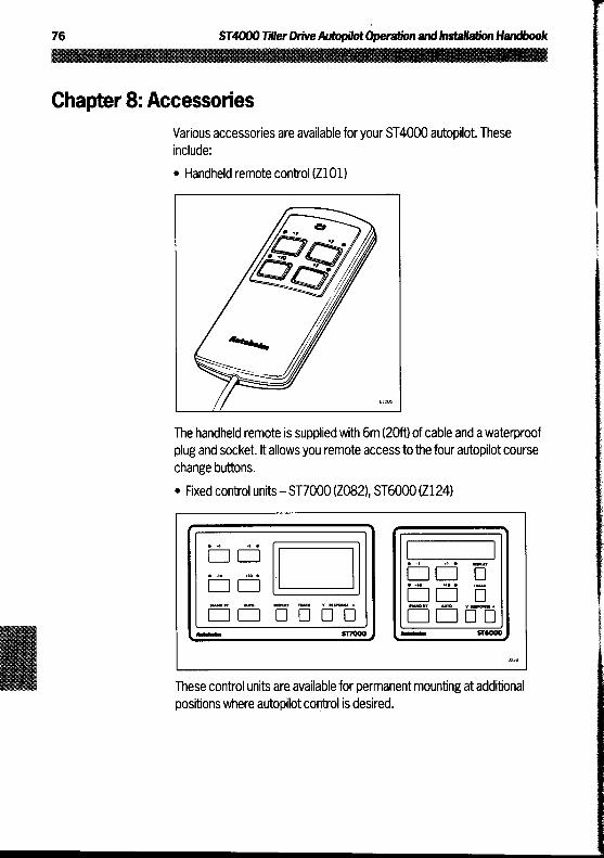
Chapter 8: AccessoriesVarious accessories are available for your ST4000 autopilot . Theseinclude :" Handheld remote control (2101)
The handheld remote is supplied with 6m (20ft) of cable and a waterproofplug and socket . It allows you remote access to the four autopilot coursechange buttons." Fixed control units-ST7000 (Z082), ST6000 (Z124)
These control units are available for permanent mounting at additionalpositions where autopilot control is desired .

Chapter8:Accessories
Digital Windvane (2087)
The digital windvane also requires the SeaTalk interface . When combinedwith the ST4000 thesetwo pieces ofequipment allow you to steeryourboat on any course relative to an apparent wind angle.
" SeaTalk Interface (2137)
The SeaTalk Interface will convert all SeaTalk data to NMEA 0183 . Thisallows you to feed NMEA 0183 Navigation data to a plotter or Speed andCompass NMEA information back to a position transducer for deadreckoning, (assuming the correct instruments are present on the SeaTalkbus to generate the information initially) ." Rudder Reference Transducer (2131)
A rudder reference transducer can be added to provide a continuous readout of rudder position .

Chapter 9: MaintenanceControl head
" In certain conditions, condensation may appear on the window . This willnot harm the unit, and can be cleared by switching on the illumination
" Never use any chemical orabrasive materialsto clean your ST4000 .If the Control head becomes dirtywipe clean with a damp cloth
Drive unit" Never use any chemical or abrasive materials to clean your drive unit .
If the drive becomes dirty wipe clean with a damp cloth
Cabling" Avoid running cables through bilges where possible and secure any
coiled lengths at regular intervals" Avoid running cables close to fluorescent lights, engines, radio transmit-
ting equipment etc" Check cabling for chafing or damage to outer casing, replace where
necessary and re-secureAdviceShould anydifficulties arise, please consult Nautech's Product Supportdepartment in the U.K . or your own National Distributor who will be able toprovide expert assistance .The working parts of the drive system are sealed and lubricated for lifeduring manufacture and therefore do not require servicing.If a faultdoes develop the autopilots plugability ensuresthat only thedefective unit be returned .Before this is done please double check that the power supply cable issound and that all connections are tight and free from corrosion . Thenrefer to thefaultfinding section of this manual . If the fault cannot be tracedthen please contact your nearest Autohelm dealer or service center foradvice .Always quote the serial number, which is printed onthe label onthe back of the control head.

Chapter 10: Faultfinding
Chapter 10: Fault Finding
All Autohelm products are subjectto a comprehensive test procedurepriorto packing and shipment . In the unlikely eventthat a fault does arisethe following check list should help cure the problem.
Fault Cause Action
Control Head display blank No supply Check supply .Check Fuse/breaker .Return head for repair
Displayed heading does not Fluxgate compass Check compass connections onchange in Standby mode mis-connected rear of Control head
Rudder position display cannot No Rudder reference Fit Rudder reference transducerbe called up transducer fitted
Set calibration level 8 to 3Calibration level 8 (Steering (See chapter 4)type) set incorrectly
Drive unit steers helm hard over Drive phase set incorrectly Refer to chapter 7 and carry outas soon as Auto is engaged the functional test .
Displayed compass heading Compass requires deviation Refer to chapter 7does not agree with Ships correction and alignment Automatic compass deviationcompass correction
Vessel turns slowly and takes a Rudder gain too low Refer to section 3.1long time to come onto course Setting up Rudder gain
Vessel overshoots when Rudder gain too high Refer to section 3.1turning onto a new course Setting up Rudder gain
Displayed rudder angle not Rudder offset incorrectly set Refer to chapter 4 Autopilotzero when helm is amidships recalibration and set up level 2
Vessel remains off course Automatic trim set up Refer to section 3.2when a course change is made incorrectly Setting up automatic trim
Pilot appears to be unstable on Northerly/Southerly heading Refer to chapter 4Northerly headings (Southerly correction not set-up Autopilot re-calibration andin Southern hemisphere) set-up levels 10 and 11

Fault Cause Action
Drive actuator hunts when Rudder damping incorrectly set Refer to chapter 4trying to position the rudder Autopilot re-calibration and
set-up level 13
Display shows Cal - Off when Calibration locked out Security protection switched onentering calibration by owner
Control head will not talk to Cabling problem Check security of all SeaTalkother SeaTalk instruments or connectors and cablesControl units
Control head will not receive Position Transducer not Refer to chapter 6 to verifyinformation from a Position transmitting correct sentances connection .Transducer(GPS, Loran etc.) Refer to section 6.3 to confirm
the correct sentances are beingtransmitted
Pilot will not auto-advance No Bearing to waypoint Refer to position transducerbetween waypoints information transmitted from handbook
the position transducer
Pilot will not display Distance to Incorrect NMEA sentances Refer to section 6.3 forwaypoint, Bearing to waypoint transmitted from Position sentance requirementor waypoint number transducer

Index
Index
AAccessories 76
Additional Control units 76Handheld control unit 76Rudder Reference Transducer 77SeaTalk interface 77Windvane 77
Auto 8Automatic Control Deadband
(Auto seastate) 12Autopilotre-calibration 31AutomaticTack (Autotack) 13Automatic Trim 30
BBasic principals (Operation) 7
CCalibration 31Cruise Speed (Calibration Level 5) 35
Disabledaccess 41Entering calibration 31Exiting calibration 32Factory settings 33CurrentVessel Latitude
(Calibration Level 11) 38Magnetic variation
(Calibration Level 9) 37Northerly/Southerly
heading error correction(Calibration Level 10) 37
Off course alarm angle(Calibration Level 6) 35
Recording settings 40Rudder damping
(Calibration Level 13) 39Rudder Gain (Calibration Level 1) 34Rudder Offset (Calibration Level 2)
34Rudder Limit(Calibration Level 3) 34Steering system type
(Calibration Level 8) 37Suggested settings
(Power/sail boats) 32
Trim Level(Calibration Level 7) 36
Turn Rate Limit(Calibration Level 4) 35
Magnetic Variation(Calibration Level 9) 37
Compass alignment 73Compass deviation correction 73Control head 45
Siting 45Mounting procedure 45Power supply connection 47SeaTalk bus connection 48
Course changes 9Crosstrackerror 21Cruise speed 35
DDodge 10
FFault Finding 79Fluxgate Compass 49
Alignment 73Cabling 51Deviation correction 73Installation 49Mounting position 49
Functional test 69Operating sense 69Rudder reference phase 70Navigation interface 70Wind transducer interface 71SeaTalk bus 72
Fuse ratings 47
HHandheld remote control unit 76
IIllumination 14

MMagnetic variation 37Maintenance 78
NNavigation Interface 67NMEA
Data Format/headers 68Transmission to otherequipment 67
Northerly heading error 37
0Off Course Alarm 14Operating sense 69
PPower supply 47
RRudder Angle display 70Rudder Gain 28Rudder Reference 51
Accessory 77Cabling 53Control dimensions 52Installation 51Mounting position 51Phase 70
SSafety 4SeaTalk
Operationwith other SeaTalkinstruments 3,49,72
Connection to bus 48Functional test 69
Sea trial 69Standby 8Steering systemtype 37Southerly turningerror 37
TTacking (Autotack) 13TrackControl 11,20
Automatic acquisition 20Crosstrack error 21Data error warning 25Large crosstrackerror warning 25Manual acquisition 20No data warning 25Operation at Low speed 23Operating hints 26Operating limitations 23Waypoint Advance 22Warning messages 25
Trim (Auto trim) 30Turn rate limit 35
WWarning messages 25
Waypoint advance 25Wlndvane (WindTrim) 11,26Accessory 77NMEA input 67Wind shift alarm 27

Nautech Limited, Anchorage Park, PortsmouthP03 5TD, England . Telephone (0705) 693611Fax (0705) 694642, Telex 86384 NAUTEC G