AUTODOME IP starlight 7000i · 2020-03-03 · 10.4 Installing the VG4-A-9543 Pipe Mount47 10.5 Wire...
72
AUTODOME IP starlight 7000i NDP‑7512‑Z30 │ NDP‑7512‑Z30K en Installation Manual
Transcript of AUTODOME IP starlight 7000i · 2020-03-03 · 10.4 Installing the VG4-A-9543 Pipe Mount47 10.5 Wire...

AUTODOME IP starlight 7000iNDP‑7512‑Z30 │ NDP‑7512‑Z30K
en Installation Manual


AUTODOME IP starlight 7000i Table of contents | en 3
Bosch Security Systems Installation Manual 2019-09 | 0.6 |
Table of contents1 Safety EN 51.1 About this Manual 51.2 Legal Information 51.3 Safety Precautions 51.4 Important Safety Instructions 61.5 Important Notices 91.6 Connection in Applications 121.7 Customer Support and Service 132 Unpacking 142.1 Parts List 142.2 Tools Required 153 Product description 174 Pre-installation Checklist 194.1 Stabilization 204.2 Configuring and Implementing Intelligent Tracking 205 Preparing the bubble 226 (Optional) Installing an SD Card 237 Replacing the trim ring and bubble 248 Mount Power Supply Box (Wall, Mast (Pole), and Corner Mounts) 259 Installing the Pendant Arm Wall, Corner, and Mast (Pole) Mounts 279.1 Description 279.2 Route Wires and Attach Connectors 279.3 Route Power through Intermediate Power Supply Box 319.4 Attach Pendant Arm to Power Supply Box 339.5 Make Connections in the Power Supply Box 359.6 Installing the VGA-PEND-WPLATE 369.7 Attach Pendant to Arm and Tighten 3910 Installing the Roof Parapet and Pipe Mounts 4110.1 Description 4110.2 Route Wires and Attach Connectors 4110.3 Attach Cover Door to Power Supply Box 4610.4 Installing the VG4-A-9543 Pipe Mount 4710.5 Wire the Pipe Interface Board 4810.6 Attach Pendant to Pipe and Tighten 5210.7 Make Connections in the Power Supply Box 5311 Finalizing installation 5412 Replacing a Pendant Bubble 5513 Connection 5613.1 Connecting the AUTODOME camera to the PC 5613.2 Power Cable and Wire Distances Guides 5613.3 Ethernet Connections 5713.4 Fiber Optic Ethernet Media Converter (Optional) 5813.5 Alarms and Relay Connections 5913.6 Audio Connections (Optional) 6214 Troubleshooting 6414.1 Rebooting the unit 6414.2 Physical reset button 6514.3 Customer Service and Support 67

4 en | Table of contents AUTODOME IP starlight 7000i
2019-09 | 0.6 | Installation Manual Bosch Security Systems
15 Maintenance 68

AUTODOME IP starlight 7000i Safety EN | en 5
Bosch Security Systems Installation Manual 2019-09 | 0.6 |
1 Safety EN1.1 About this Manual
This manual has been compiled with great care and the information it contains has beenthoroughly verified. The text was complete and correct at the time of printing. Because of theongoing development of products, the content of the manual may change without notice.Bosch Security Systems accepts no liability for damage resulting directly or indirectly fromfaults, incompleteness, or discrepancies between the manual and the product described.
1.2 Legal InformationCopyrightThis manual is the intellectual property of Bosch Security Systems, and is protected bycopyright. All rights reserved.TrademarksAll hardware and software product names used in this document are likely to be registeredtrademarks and must be treated accordingly.
1.3 Safety Precautions
Danger!Indicates a hazardous situation which, if not avoided, will result in death or serious injury.
!
Warning!Indicates a hazardous situation which, if not avoided, could result in death or serious injury.
!
Caution!Indicates a hazardous situation which, if not avoided, could result in minor or moderateinjury.
Notice!Indicates a situation which, if not avoided, could result in damage to the equipment orenvironment, or data loss.

6 en | Safety EN AUTODOME IP starlight 7000i
2019-09 | 0.6 | Installation Manual Bosch Security Systems
1.4 Important Safety InstructionsRead, follow, and retain for future reference all of the following safety instructions. Heed allwarnings on the unit and in the operating instructions before operating the unit.1. Cleaning - Unplug the unit from the outlet before cleaning. Follow any instructions
provided with the unit. Generally, using a dry cloth for cleaning is sufficient, but a moistfluff-free cloth or leather shammy may also be used. Do not use liquid cleaners or aerosolcleaners.
2. Heat Sources - Do not install the unit near any heat sources such as radiators, heaters,stoves, or other equipment (including amplifiers) that produce heat.
3. Ventilation - Any openings in the unit enclosure are provided for ventilation to preventoverheating and ensure reliable operation. Do not block or cover these openings. Do notplace the unit in an enclosure unless proper ventilation is provided, or the manufacturer'sinstructions have been adhered to.
4. Object and liquid entry - Never push objects of any kind into this unit through openingsas they may touch dangerous voltage points or short-out parts that could result in a fireor electrical shock. Never spill liquid of any kind on the unit. Do not place objects filledwith liquids, such as vases or cups, on the unit.
5. Lightning - For added protection during a lightning storm, or when leaving this unitunattended and unused for long periods, unplug the unit from the wall outlet anddisconnect the cable system. This will prevent damage to the unit from lightning andpower line surges.
6. Controls adjustment - Adjust only those controls specified in the operating instructions.Improper adjustment of other controls may cause damage to the unit. Use of controls oradjustments, or performance of procedures other than those specified, may result inhazardous radiation exposure.
7. Overloading - Do not overload outlets and extension cords. This can cause fire orelectrical shock.
8. Power cord and plug protection - Protect the plug and power cord from foot traffic,being pinched by items placed upon or against them at electrical outlets, and its exit fromthe unit. For units intended to operate with 230 VAC, 50 Hz, the input and output powercord must comply with the latest versions of IEC Publication 227 or IEC Publication 245.
9. Power disconnect - Units have power supplied to the unit whenever the power cord isinserted into the power source, or when High Power-over-Ethernet (High PoE) power isprovided over the Ethernet CAT 5E/6 cable. The unit is operational only when the ON/OFFswitch is in the ON position. The power cord is the main power disconnect device forswitching off the voltage for all units. When High PoE or PoE+ (820.3at) is used to powerthe unit, the power is provided over the Ethernet cable, which is then the main powerdisconnect device for switching off the voltage for all units.
10. Power sources - Operate the unit only from the type of power source indicated on thelabel. Before proceeding, be sure to disconnect the power from the cable to be installedinto the unit.For battery powered units, refer to the operating instructions.For external power supplied units, use only the recommended or approved powersupplies.For limited power source units, this power source must comply with EN60950.Substitutions may damage the unit or cause fire or shock.For 24 VAC units, voltage applied to the unit's power input should not exceed ±10%, or28 VAC. User-supplied wiring must comply with local electrical codes (Class 2 powerlevels). Do not ground the supply at the terminals or at the unit's power supply terminals.

AUTODOME IP starlight 7000i Safety EN | en 7
Bosch Security Systems Installation Manual 2019-09 | 0.6 |
If unsure of the type of power supply to use, contact your dealer or local power company.11. Servicing - Do not attempt to service this unit yourself. Opening or removing covers may
expose you to dangerous voltage or other hazards. Refer all servicing to qualified servicepersonnel.
12. Damage requiring service - Unplug the unit from the main AC power source and referservicing to qualified service personnel when any damage to the equipment has occurred,such as:the power supply cord or plug is damaged;exposure to moisture, water, and/or inclement weather (rain, snow, etc.);liquid has been spilled in or on the equipment;an object has fallen into the unit;unit has been dropped or the unit cabinet is damaged;unit exhibits a distinct change in performance;unit does not operate normally when the user correctly follows the operating instructions.
13. Replacement parts - Be sure the service technician uses replacement parts specified bythe manufacturer, or that have the same characteristics as the original parts.Unauthorized substitutions may cause fire, electrical shock, or other hazards.
14. Safety check - Safety checks should be performed upon completion of service or repairsto the unit to ensure proper operating condition.
15. Installation - Install in accordance with the manufacturer's instructions and in accordancewith applicable local codes.
16. Attachments, changes or modifications - Only use attachments/accessories specified bythe manufacturer. Any change or modification of the equipment, not expressly approvedby Bosch, could void the warranty or, in the case of an authorization agreement, authorityto operate the equipment.
8 en | Safety EN AUTODOME IP starlight 7000i
2019-09 | 0.6 | Installation Manual Bosch Security Systems
!
Caution!Installation must be made by qualified personnel and conform to ANSI/NFPA 70 (the NationalElectrical Code® (NEC)), Canadian Electrical Code, Part I (also called CE Code or CSA C22.1),and all applicable local codes. Bosch Security Systems accepts no liability for any damages orlosses caused by incorrect or improper installation.
!
Warning!INSTALL EXTERNAL INTERCONNECTING CABLES IN ACCORDANCE TO NEC, ANSI/NFPA70(FOR US APPLICATION) AND CANADIAN ELECTRICAL CODE, PART I, CSA C22.1 (FOR CANAPPLICATION) AND IN ACCORDANCE TO LOCAL COUNTRY CODES FOR ALL OTHERCOUNTRIES. BRANCH CIRCUIT PROTECTION INCORPORATING A 20 A, 2-POLE LISTEDCIRCUIT BREAKER OR BRANCH RATED FUSES ARE REQUIRED AS PART OF THE BUILDINGINSTALLATION. A READILY ACCESSIBLE 2-POLE DISCONNECT DEVICE WITH A CONTACTSEPARATION OF AT LEAST 3 mm MUST BE INCORPORATED.
!
Warning!ROUTING OF EXTERNAL WIRING MUST BE DONE THROUGH A PERMANENTLY EARTHEDMETAL CONDUIT.
!
Warning!THE CAMERA MUST BE MOUNTED DIRECTLY AND PERMANENTLY TO A NON-COMBUSTIBLESURFACE.
Notice!Always use a shielded twisted pair (STP) connection cable and a shielded RJ45 network cableconnector where the camera is used outdoors or the network cable is routed outdoors.Always use shielded cables/connectors in demanding indoor electrical environments wherethe network cable is located in parallel with electrical mains supply cables, or where largeinductive loads such as motors or contactors are near the camera or its cable.
Notice!Bosch recommends the use of surge/lightning protection devices (sourced locally) to protectnetwork and power cables and the camera installation site. Refer to NFPA 780, Class 1 & 2,UL96A, or the equivalent code appropriate for your country/region, and to local buildingcodes. Refer also to the installation instructions of each device (surge protector where thecable enters the building, midspan, and camera).
If a power adapter supplies power to the camera, you must ground the adapter properly.
AUTODOME IP starlight 7000i Safety EN | en 9
Bosch Security Systems Installation Manual 2019-09 | 0.6 |
1.5 Important Notices
Accessories - Do not place this unit on an unstable stand, tripod, bracket, ormount. The unit may fall, causing serious injury and/or serious damage tothe unit. Use only with mounting solutions specified by the manufacturer.When a cart is used, use caution and care when moving the cart/unitcombination to avoid injury from tip-over. Quick stops, excessive force, oruneven surfaces may cause the cart/unit combination to overturn. Mount theunit per the installation instructions.
Adjustment of controls - Adjust only those controls specified in the operating instructions.Improper adjustment of other controls may cause damage to the unit.Camera signal - Protect the cable with a primary protector if the camera signal is beyond 140feet, in accordance with NEC800 (CEC Section 60).Environmental statement - Bosch has a strong commitment towards the environment. Thisdevice has been designed to respect the environment as much as possible.Electrostatic-sensitive device - Use proper ESD safety precautions when handling the camerato avoid electrostatic discharge.Fuse rating - For security protection of the device, the branch circuit protection must besecured with a maximum fuse rating of 16A. This must be in accordance with NEC800 (CECSection 60).
Grounding:- Connect outdoor equipment to the unit's inputs only after this unit has had its groundterminal connected properly to a ground source.- Disconnect the unit's input connectors from outdoor equipment before disconnecting thegrounding terminal.- Follow proper safety precautions such as grounding for any outdoor device connected to thisunit.U.S.A. models only - Section 810 of the National Electrical Code, ANSI/NFPA No.70, providesinformation regarding proper grounding of the mount and supporting structure, size ofgrounding conductors, location of discharge unit, connection to grounding electrodes, andrequirements for the grounding electrode.Outdoor signals - The installation for outdoor signals, especially regarding clearance frompower and lightning conductors and transient protection, must be in accordance with NEC725and NEC800 (CEC Rule 16-224 and CEC Section 60).Refer to the ”Best Practices for Outdoor Installation” section of the manual for moreinformation on outdoor installations.Permanently connected equipment - Incorporate a readily accessible disconnect device in thebuilding installation wiring.Power lines - Do not locate the camera near overhead power lines, power circuits, orelectrical lights, nor where it may contact such power lines, circuits, or lights.Damage requiring service – Unplug the devices from the main AC power source and referservicing to qualified service personnel whenever any damage to the device has occurred,such as:- the power supply cable is damaged;- an object has fallen on the device;- the device has been dropped, or its enclosure has been damaged;- the device does not operate normally when the user follows the operating instructionscorrectly.

10 en | Safety EN AUTODOME IP starlight 7000i
2019-09 | 0.6 | Installation Manual Bosch Security Systems
Servicing - Do not attempt to service this device yourself. Refer all servicing to qualifiedservice personnel.This device has no user-serviceable parts.
Notice!This is a class A product. In a domestic environment this product may cause radiointerference, in which case the user may be required to take adequate measures.
Notice!Ce produit est un appareil de Classe A. Son utilisation dans une zone résidentielle risque deprovoquer des interférences. Le cas échéant, l’utilisateur devra prendre les mesuresnécessaires pour y remédier.

AUTODOME IP starlight 7000i Safety EN | en 11
Bosch Security Systems Installation Manual 2019-09 | 0.6 |
FCC & ICES Information(U.S.A. and Canadian Models Only)This device complies with part 15 of the FCC Rules. Operation is subject to the followingconditions:– this device may not cause harmful interference, and– this device must accept any interference received, including interference that may cause
undesired operation.NOTE: This equipment has been tested and found to comply with the limits for a Class Adigital device, pursuant to Part 15 of the FCC Rules and ICES-003 of Industry Canada. Theselimits are designed to provide reasonable protection against harmful interference when theequipment is operated in a commercial environment. This equipment generates, uses, andradiates radio frequency energy and, if not installed and used in accordance with theinstruction manual, may cause harmful interference to radio communications. Operation ofthis equipment in a residential area is likely to cause harmful interference, in which case theuser will be required to correct the interference at his expense.Intentional or unintentional modifications, not expressly approved by the party responsible forcompliance, shall not be made. Any such modifications could void the user's authority tooperate the equipment. If necessary, the user should consult the dealer or an experiencedradio/television technician for corrective action.

12 en | Safety EN AUTODOME IP starlight 7000i
2019-09 | 0.6 | Installation Manual Bosch Security Systems
1.6 Connection in Applications24 VAC power source: This unit is intended to operate with a limited power source. The unitis intended to operate at 24 VAC (if High PoE is not available). User supplied wiring must be incompliance with electrical codes (Class 2 power levels).High Power-over-Ethernet (High PoE): This unit can by powered via High PoE. To power theunit this way, use only approved High PoE devices - those offered or recommended by Bosch.High PoE can be connected at the same time as a 24 VAC power supply. If auxiliary power (24VAC to camera and to heater) and High PoE are applied simultaneously, the camera willselects auxiliary input (24 VAC) as the primary power source.For pendant models used in outdoor applications that require heaters, a High PoE Midspan(60 W) by Bosch is required to power both the camera and its internal heaters.For in-ceiling or indoor pendant applications that don’t require heater power, standard PoE+(IEEE 802.3at) midspans or switches can be used to power the camera.

AUTODOME IP starlight 7000i Safety EN | en 13
Bosch Security Systems Installation Manual 2019-09 | 0.6 |
1.7 Customer Support and ServiceIf this unit needs service, contact the nearest Bosch Security Systems Service Center forauthorization to return and shipping instructions.USATelephone: 800-366-2283Fax: 800-366-1329Email: [email protected] ServiceTelephone: 888-289-0096Fax: 585-223-9180Email: [email protected] SupportTelephone: 800-326-1450Fax: 717-735-6560Email: [email protected]: 514-738-2434Fax: 514-738-8480Europe, Middle East, Africa, and Asia Pacific RegionsPlease contact your local distributor or Bosch sales office. Use this link:https://www.boschsecurity.com/corporate/where-to-buy/index.html
More InformationFor more information, please contact the nearest Bosch Security Systems location or visitwww.boschsecurity.com.
14 en | Unpacking AUTODOME IP starlight 7000i
2019-09 | 0.6 | Installation Manual Bosch Security Systems
2 Unpacking– This equipment should be unpacked and handled with care. Check the exterior of the
packaging for visible damage. If an item appears to have been damaged in shipment,notify the shipper immediately.
– Verify that all the parts listed in the Parts List below are included. If any items aremissing, notify your Bosch Security Systems Sales or Customer Service Representative.
– Do not use this product if any component appears to be damaged. Please contact BoschSecurity Systems in the event of damaged goods.
– The original packing carton (if undamaged) is the safest container in which to transportthe unit and must be used if returning the unit for service. Save it for possible future use.
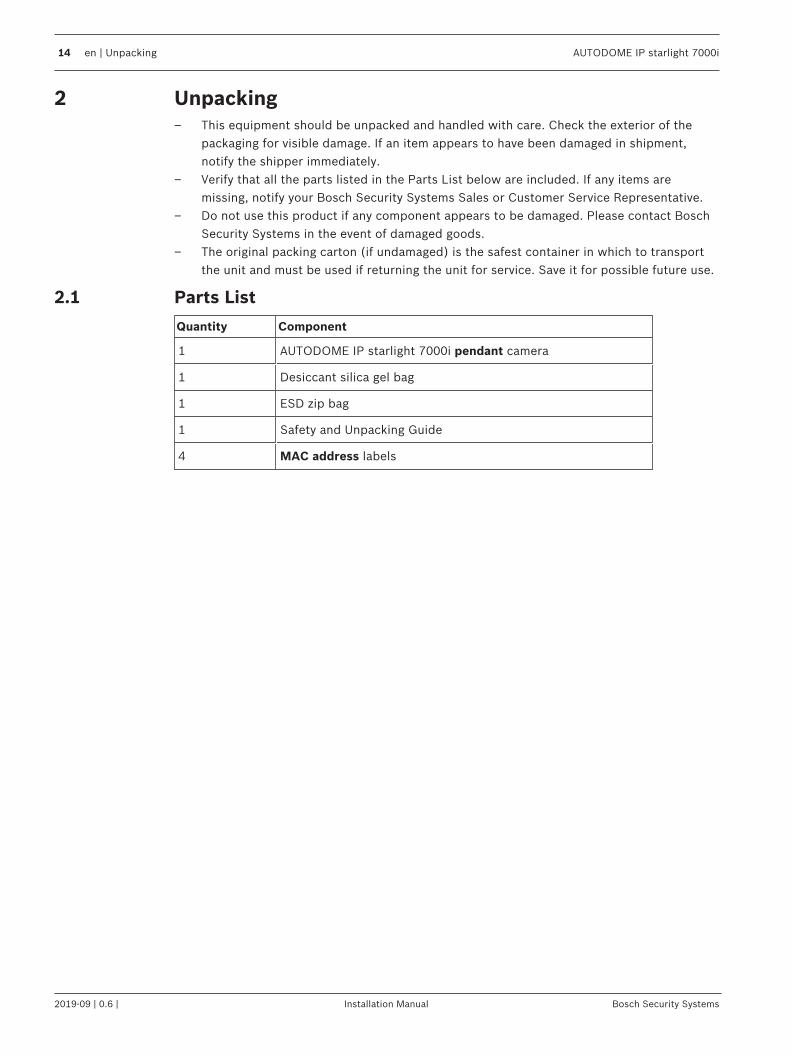
2.1 Parts List
Quantity Component
1 AUTODOME IP starlight 7000i pendant camera
1 Desiccant silica gel bag
1 ESD zip bag
1 Safety and Unpacking Guide
4 MAC address labels
AUTODOME IP starlight 7000i Unpacking | en 15
Bosch Security Systems Installation Manual 2019-09 | 0.6 |
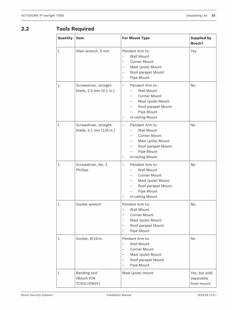
2.2 Tools Required
Quantity Item For Mount Type Supplied byBosch?
1 Allen wrench, 5 mm Pendant Arm to:– Wall Mount– Corner Mount– Mast (pole) Mount– Roof parapet Mount– Pipe Mount
Yes
1 Screwdriver, straight-blade, 2.5 mm (0.1 in.)
– Pendant Arm to:– Wall Mount– Corner Mount– Mast (pole) Mount– Roof parapet Mount– Pipe Mount
– In-ceiling Mount
No
1 Screwdriver, straight-blade, 3.1 mm (1/8 in.)
– Pendant Arm to:– Wall Mount– Corner Mount– Mast (pole) Mount– Roof parapet Mount– Pipe Mount
– In-ceiling Mount
No
1 Screwdriver, No. 2Phillips
– Pendant Arm to:– Wall Mount– Corner Mount– Mast (pole) Mount– Roof parapet Mount– Pipe Mount
– In-ceiling Mount
No
1 Socket wrench Pendant Arm to:– Wall Mount– Corner Mount– Mast (pole) Mount– Roof parapet Mount– Pipe Mount
No
1 Socket, 9/16-in. Pendant Arm to:– Wall Mount– Corner Mount– Mast (pole) Mount– Roof parapet Mount– Pipe Mount
No
1 Banding tool(Bosch P/NTC9311PM3T)
Mast (pole) mount Yes, but soldseparatelyfrom mount

16 en | Unpacking AUTODOME IP starlight 7000i
2019-09 | 0.6 | Installation Manual Bosch Security Systems
1 Right angle NPS conduitconnector, 3/4 in. (20-mm)
Mast (pole) mount with VGA-PEND-WPLATE
No
1 Screwdriver, mediumstraight blade
– Roof parapet Mount– Pipe Mount
No
1 Screwdriver, No. 1Phillips
– Roof parapet Mount– Pipe Mount
No
1 Pipe wrench – Roof parapet Mount– Pipe Mount
No
1 Barrel connector – Roof parapet Mount– Pipe MountOnly if installing a fiber optic model
No
The following table lists additional products, sold separately by Bosch or other manufacturers,necessary to install AUTODOME cameras.
Quantity Product Part Number Size
1 SD card (user-supplied)
--- Water tight metal conduit (user-supplied) 20 mm (0.75 in.)
-- UL-listed liquid tight strain reliefs (user-supplied)
-- Weatherproof sealant (user-supplied)
4 Studs, stainless steel, corrosion-resistant,
(user-supplied) 6.4 mm (0.25 in.)to 8 mm (5/16 in.)

AUTODOME IP starlight 7000i Product description | en 17
Bosch Security Systems Installation Manual 2019-09 | 0.6 |
3 Product descriptionThe AUTODOME IP starlight 7000i camera incorporates the latest in Video Analytics, starlighttechnology, and video streaming. With starlight imaging technology for excellent low-lightsensitivity and the most robust Intelligent Video Analytics on the market, the camera deliversunmatched picture quality. Even under the most challenging light conditions, the 30x PTZdome camera delivers high-definition (HD) 1080p video. Easy to install, the camera is availablein either a field-proven, outdoor pendant housing or an indoor, in-ceiling housing.The camera has been designed for quick and easy installation, a key feature from Bosch IPvideo security products.All housings feature recessed screws and latches for increased tamper resistance.In an enclosed installation area, still air can cause the operating temperature of the camera togo above the maximum. If you install a camera in an enclosed area, make sure that theoperating temperature of the camera does not go above the maximum temperature. Themaximum operating temperature is:– +40 °C (+104 °F) for in-ceiling models– +55 °C (+131 °F) for pendant modelsMake sure that air circulates around the camera to supply cooling.The following table lists the optional parts, sold separately, that you may need for attaching aPendant to the Arm Wall, Corner, or Mast mount packages.
Mounting Options Part Numbers
Pendant Arm (Only) VGA-PEND-ARM
Pendant Arm with Mounting Plate(24 V VG5 models only, no power supply box)
VGA-PEND-WPLATE
Pendant Arm with one of the following Power Supply Boxes:
– Power Box without transformer (24 VAC) VG4-A-PA0
– Power Box with 120 VAC transformeror with 230 VAC transformer
VG4-A-PA1VG4-A-PA2
Power Supply Box and cover with 120 VAC transformer or with 230 VAC transformer
VG4-A-PSU1 VG4-A-PSU2
Trim Skirt for Power Supply Box (optional) VG4-A-TSKIRT
Bosch High PoE 60W midspan NPD-6001A
Corner Mount Kit
– Corner Mount Plate VG4-A-9542
Mast (Pole) Mount Kit
– Mast Mount Plate VG4-A-9541
– Fiber Optic Ethernet Media Converter Kit VG4-SFPSCKT

18 en | Product description AUTODOME IP starlight 7000i
2019-09 | 0.6 | Installation Manual Bosch Security Systems
The following table lists the mandatory parts, sold separately, that you will need for attachinga Pendant to the Roof Parapet and Pipe mount packages:
Mounting Options Part Numbers
Parapet (Roof) Mount with one of the following Power Supply Boxes: VGA-ROOF-MOUNT
– Power Supply Box and cover with 120 VAC transformeror with 230 VAC transformer
VG4-A-PSU1 VG4-A-PSU2
Pipe Mount with one of the following Power Supply Boxes: VG4-A-9543
– Power Supply Box and cover with 120 VAC transformer or with 230 VAC transformer
VG4-A-PSU1 VG4-A-PSU2
The following table lists the optional parts, sold separately, that you may need for attaching aPendant to the Roof Parapet and Pipe mount packages:
Mounting Options Part Numbers
Optional Flat Roof Mount Adapter for VGA-ROOF-MOUNT LTC 9230/01

AUTODOME IP starlight 7000i Pre-installation Checklist | en 19
Bosch Security Systems Installation Manual 2019-09 | 0.6 |
4 Pre-installation Checklist1. Determine the location and distance for the power supply box based on its voltage and
current consumption.You may choose to route the main power supply through an intermediate power supplybox (VG4-PSU1 or VG4-PSU2) before connecting the power to the pendant arm powersupply box (VG4-PA0).
!
Caution!Select a rigid mounting location to prevent excessive vibration to the camera.
2. Use only UL-listed liquid tight strain reliefs for conduits to the Power Supply Box toensure that water cannot enter the box. You must use water tight conduits and fittings tomeet NEMA 4 standards.
3. Purchase the appropriate mounting hardware to use, depending on the location of thecamera, either wall mount, corner mount, or mast (pole) mount.If your application contains a Power Supply Box, refer to Mount Power Supply Box (Wall,Mast (Pole), and Corner Mounts), page 25.If you are using the Mounting Plate with a 24 V AUTODOME camera, refer to Installing theVGA-PEND-WPLATE, page 36.
!
Warning!For units intended to be installed outdoors: All wiring (power and I/O cabling) connecting tothe unit must be routed separately inside different permanently earthed metal conduits (notsupplied).
!
Warning!To minimize the potential for corrosion on the housing, use only Bosch hardware and mounts.See number 5 (Installation in a corrosive environment) in the section Recommended Use ofYour Camera for more information.
4. Install all external wiring including power, control, video coax, alarms I/O, relay I/O, andfiber optic cabling. Refer to the Connection, page 56 chapter for required cable typesand allowed lengths.
!
Warning!Install external interconnecting cables in accordance to NEC, ANSI/NFPA70 (for USapplication) and Canadian Electrical Code, Part I, CSA C22.1 (for CAN application) and inaccordance to local country codes for all other countries.Branch circuit protection incorporating a 20 A, 2-pole Listed Circuit Breaker or Branch RatedFuses are required as part of the building installation. A readily accessible 2-pole disconnectdevice with a contact separation of at least 3 mm must be incorporated.24 VAC Class 2 power supply only.
5. If you plan to use the Intelligent Tracking feature, refer to Configuring and ImplementingIntelligent Tracking, page 20 before mounting the camera.

20 en | Pre-installation Checklist AUTODOME IP starlight 7000i
2019-09 | 0.6 | Installation Manual Bosch Security Systems
4.1 StabilizationSurveillance cameras are susceptible to vibrations caused by wind or vibrations emanatingfrom the medium to which the camera is attached. Cameras attached to a pole, roof, or to abridge are especially vulnerable. Bosch offers the following recommendations to stabilize anAUTODOME camera and to decrease the affects of vibration on transmitted images, privacymasks, and Intelligent Tracking.
Pole and Mast Mounts– Use a pendant arm with the Pole Mount Adapter (VG4-A-9541).
– Do not attach a parapet mount to a pole or mast.– Use a pole designed specifically for CCTV cameras:
– Do not use a tapered pole.– Do not use a pole that has signs or other equipment attached.
– Consult EPA rating / Wind load data to select an appropriate pole.
Roof Mounts– Mount the camera in the most stable location on the roof.– Avoid locations affected by vibrations such as those caused by a rooftop air conditioner.– Use guy wires to stabilize the AUTODOME against strong winds.– Use the LTC 9230/01 Flat Roof Mount Adapter where appropriate. This adapter is made
specifically for AUTODOME roof applications.
Extreme Mount ApplicationsUnique camera mounting applications that are impacted by extreme high winds, heavy traffic,or other conditions may require additional measures to stabilize the camera. Contact amanufacturer that specializes in passive vibration suppression using either damping orisolation.
4.2 Configuring and Implementing Intelligent TrackingConfiguring Intelligent TrackingThe camera utilizes the built-in Intelligent Video Analytics (IVA) to continuously follow anindividual or object even if it passes behind a Privacy Mask or a stationary object. The camerauses objects detected by IVA in a stationary preset position to activate the Intelligent Trackingfeature.The Intelligent Tracking feature allows continuous on-screen following of an individual or anobject. This feature operates by recognizing an object in motion and zooms in toapproximately 50% (default Tracker zoom threshold) of the field of view for an average targetheight of six feet. This feature controls the pan/tilt/zoom actions of the camera to keep theselected object in the scene.

AUTODOME IP starlight 7000i Pre-installation Checklist | en 21
Bosch Security Systems Installation Manual 2019-09 | 0.6 |
12 ft (3.66 m)
6 ft (1.83 m)
8 ft (2.44 m)
H
D
Guidelines for Implementing Intelligent TrackingFactors such as the viewing angle and unwanted motion (from trees, for example) mayinterfere with Intelligent Tracking operation. Use the following recommendations to ensuresmooth Intelligent Tracking operation:– Mount/Mounting Surface Stability
– Mount the camera in the most stable position. Avoid locations affected by vibrations,such as those caused by a roof-top air conditioner. These vibrations may causecomplications when the camera zooms-in on a target.
– Use the pendant arm mount, if possible. This mount option provides the moststability for the camera.
– Use guy wires to protect against strong winds if using the parapet mount.– Field of View
– Select a location and viewing angle that allows the flow of people to move across thecamera’s field of view.
– Avoid motion that moves directly towards the camera.– Avoid locations that attract large numbers of people, such as retail stores or
intersections. Intelligent Tracking is optimized for scenes with very few movingobjects.
– Unwanted Motion– Avoid neon lights, flashing lights, night time lights, and reflected light (from a
window or mirror, for example). The flickering of these lights can affect theIntelligent Tracking operation.
– Avoid motion from moving leaves/branches that present a persistent fixed motion.

22 en | Preparing the bubble AUTODOME IP starlight 7000i
2019-09 | 0.6 | Installation Manual Bosch Security Systems
5 Preparing the bubbleNotice!To avoid excessive moisture saturation inside the housing, limit the amount of time that thebubble is disconnected from the housing. Bosch recommends that the bubble be removedfrom the housing for no more than five (5) minutes.
Remove the bubble from a pendant housing1. Using both hands, apply a firm counterclockwise (looking up at the dome) rotational
force on the pendant bubble assembly to set the bubble latch.2. Insert a small (2 mm) straight blade screw driver into the release opening in the bubble
trim-ring to release the lock, and then remove the screwdriver.
Figure 5.1: Remove the bubble
4 Firmly rotate the bubble counterclockwise approximately 20 degrees until the bubbleassembly releases from the pendant housing.

AUTODOME IP starlight 7000i (Optional) Installing an SD Card | en 23
Bosch Security Systems Installation Manual 2019-09 | 0.6 |
6 (Optional) Installing an SD CardThe camera can accept a customer-supplied SDHC or SDXC memory card (hereafter referredto as “SD card”) for local storage. (The camera will not accept MicroSD cards.) Using an SDcard is optional.Note: Disconnect power to the camera while adding or removing an SD card.1. Follow the steps in one of these sections (depending on the type of camera mount):
Remove bubble from in-ceiling housing or Remove bubble from pendant housing.2. Locate the SD card slot (highlighted in the figure below).
3. Orient the card so that the side with the golden contacts faces away from the dome andtowards the housing. The contacts should be at the bottom as you hold the SD card.
4. Slide the SD card into the slot. Press down the end of the SD cards until you hear a clickand the card locks into place.
5. Follow the steps in one of these sections (depending on the type of camera mount):Replace the bubble in an in-ceiling housing or Replace the bubble in a pendant housing.
24 en | Replacing the trim ring and bubble AUTODOME IP starlight 7000i
2019-09 | 0.6 | Installation Manual Bosch Security Systems
7 Replacing the trim ring and bubbleReplace the bubble in a pendant housing1. Insert the bubble and trim ring assembly into the pendant housing.2. Rotate the assembly clockwise until it locks. The latch mechanism makes a click when it
locks.

AUTODOME IP starlight 7000i Mount Power Supply Box (Wall, Mast (Pole), and Corner Mounts) | en 25
Bosch Security Systems Installation Manual 2019-09 | 0.6 |
8 Mount Power Supply Box (Wall, Mast (Pole), andCorner Mounts)Before mounting the Power Supply Box, decide if you should wire the box through the holes inthe bottom or back of the box. If wiring the box through the back, move the two (2) seal plugsto the bottom through the holes before mounting.
Notice!Use 3/4-inch (20-mm) NPS fittings for the holes on the bottom and back of the box. Use 1/2-inch (15-mm) NPS fittings for the side holes.
Figure 8.1: Power Supply Wall, Mast (Pole), and Corner Mounts
1. Use the wall mount template supplied in the packaging box to locate the four (4)mounting holes for the Power Supply Box.
2. Drill four (4) holes for the mounting anchors. If installing outdoors, apply a weatherproofsealant around each hole at the mounting surface.
!
Warning!A stud diameter of 6.4 mm (1/4 inch) to 8 mm (5/16 inch) able to withstand a 120 kg (265 lb)pull-out force is recommended. The mounting material must be able to withstand this pull outforce. For example, 19-mm (3/4-inch) minimum for plywood.
3. Place the Power Supply Box into the optional Trim Skirt.4. Secure the Power Supply Box to the mounting surface.
For a Wall installation: Use four (4) corrosion-resistant, stainless steel studs (notsupplied). Then proceed to Step 5 below.For a Corner installation: Secure the Corner Plate to the wall corner using four (4) studs(not included). Then proceed to Step 5 below. For a Mast or a pole installation: The metal straps included with the Mast mountaccommodate a pole with a diameter of 100–380 mm (4–15 in.). You must use a bandingtool (sold separately) for a mast or pole installation. Follow the instructions providedwith the banding tool to securely mount the Mast Plate to the pole. Contact your BoschSales Representative to order Banding Tool P/N TC9311PM3T.
5. Secure the Power Supply Box to the Corner Plate or Mast Plate using the four (4) 3/8 x1-3/4-inch bolts and split lock washers (supplied).
6. Attach 3/4-inch (20-mm) NPS watertight, earth-grounded conduit pipe fittings (notsupplied) to the bottom or back holes of the Power Supply Box through which you willrun the power, video, and control data wires.
26 en | Mount Power Supply Box (Wall, Mast (Pole), and Corner Mounts) AUTODOME IP starlight 7000i
2019-09 | 0.6 | Installation Manual Bosch Security Systems
!
Warning!For units intended to be installed outdoors: All wiring (power and I/O cabling) connecting tothe unit must be routed separately inside different permanently earthed metal conduits (notsupplied).

AUTODOME IP starlight 7000i Installing the Pendant Arm Wall, Corner, and Mast (Pole) Mounts | en 27
Bosch Security Systems Installation Manual 2019-09 | 0.6 |
9 Installing the Pendant Arm Wall, Corner, and Mast(Pole) Mounts
9.1 DescriptionThis chapter details how to install an AUTODOME to a Wall, Corner, or Mast (pole) mount. Anydifferences to the installation between these two mounting systems are noted.
9.2 Route Wires and Attach Connectors
Notice!If you plan to route the power through an intermediate power supply box, refer to RoutePower through Intermediate Power Supply Box, page 31.
Power wires must be routed to the left (front) side of the Power Supply Box through aseparate electrically earth-grounded conduit. All video, control, and alarm wires must berouted through a second electrically earth-grounded conduit to the right side of the box.
!
Warning!External interconnecting cables are to be installed in accordance to NEC, ANSI/NFPA70 (forUS application) and Canadian Electrical Code, Part I, CSA C22.1 (for CAN application) and inaccordance to local country codes for all other countries.Branch circuit protection incorporating a 20 A, 2-pole Listed Circuit Breaker or Branch RatedFuses are required as part of the building installation. A readily accessible 2-pole disconnectdevice with a contact separation of at least 3 mm (0.12 in.) must be incorporated.
Making the Connections
Notice!Refer to the Connection, page 56 chapter for wire specifications and distances.
1. Route all video, control, and alarm wires through the earth-grounded conduit fitting onthe right side of the power box.
2. Route the high voltage 115/230 VAC lines through the earth-grounded conduit fitting onthe left side of the box. The Power Supply Box with a transformer comes with a barrierthat separates the high voltage side on the left, from the low voltage 24 VAC side on theright.
3. Cut and trim all wires with sufficient slack to reach their connector terminals in the box,but not so long as to be pinched by or to obstruct closing the Pendant Arm. Refer to theimage above for the connector locations.
4. Attach the supplied 3-pin Power Plug to the incoming power wires. Refer to connectorP101 for wire connections.
5. If audio input and/or audio output is required, attach the supplied 6-pin SERIALCOMMUNICATIONS to P106 in the Power Supply Box. Refer to connector P106 in thePower Supply Box Connections section below.
6. Attach an RJ45 plug to the incoming Ethernet cable.
Connecting Alarm Inputs and Outputs4 To connect alarm inputs and outputs, attach the supplied 6-pin Alarms In and the 4-pin
Alarms Out connector plugs with flying lead wires to the appropriate incoming alarmwires. Alarm Out 4 is a relay.

28 en | Installing the Pendant Arm Wall, Corner, and Mast (Pole) Mounts AUTODOME IP starlight 7000i
2019-09 | 0.6 | Installation Manual Bosch Security Systems
1
1
2
3
4
5
6
2
3
4 N.O
. CO
M
N
.C.
A
1
GN
D A2
1
PIN
PIN
P102
P103
P104
WHITE
ORANGE
BROWN
GREEN
WHITE
ORANGE
BROWN
GREEN
YELLOW
BLUE
2
3
4
5
6
7
Figure 9.1: Alarm and relay connectors
1 4-pin AlarmConnector (P102)
2 6-pin Alarm InConnector (P103)
3 7-pin Relay Connector (P104)
Pin Description Pin Description Pin Description
1 Alarm Out 1 1 Alarm in 3 1 Alarm Out 4 Normally Open
2 Alarm Out 2 2 Alarm in 4 2 Alarm Out 4 COM
3 Alarm Out 3 3 Alarm in 5 3 Alarm Out 4 Normally Closed
4 Alarm Ground 4 Alarm in 6 4 Earth Ground
5 Alarm in 7 5 Analog Alarm 1
6 Alarm Ground 6 Analog Alarm 2
7 Ground
For in-ceiling mount only: Low Voltage TTL (3.3V) can also be used.
4 If you are connecting supervised alarms and relays, attach the supplied 7-pin RelayConnector to the appropriate incoming wires. Refer to Make Connections in the PowerSupply Box, page 35 for additional information.

AUTODOME IP starlight 7000i Installing the Pendant Arm Wall, Corner, and Mast (Pole) Mounts | en 29
Bosch Security Systems Installation Manual 2019-09 | 0.6 |
Power Supply Box ConnectionsThe following figure is a detailed illustration of the Pendant Arm Power Supply Box, whichincludes the fuse specifications.
TRANSFORMER
(115/230VAC
MODELS)
P101
1 2 3
6 5 4 3 2 1 6 5 4 3 2 1
P106
XF102
XF103
XF101
J103
J103
J103
J103
J102J102J102J102
J101
J101
J101
J101
J101
J101
J101
J101
J101
J101
J101
J101
J101
J101
J101
J101
J101
J101
J101
J101
J101
J101
J101
J101
J101
J101
J101
J101
J101
J101
J101
J101
J101
J101
J101
J101
J101
J101
J101
J101
J101
J101
J101
(LED)
P1
07
5 4
3 2
1
GND TXD RXD C+ C-
P105
GND TXD RXD C+ C-
HT
R D
OM
E
a
(FU
SE
)(F
US
E)
(FU
SE
)(F
US
E)
(FU
SE
)(F
US
E)
(FU
SE
)(F
US
E)
(FU
SE
)(F
US
E)
(FU
SE
)
(FU
SE
)(F
US
E)
(FU
SE
)(F
US
E)
(FU
SE
)(F
US
E)
(FU
SE
)(F
US
E)
(FU
SE
)
LINE NC NEUT
Figure 9.2: Pendant arm power supply box
1 Ground Screw 7 P101 Connector; Power In (120 VAC / 220VAC)
2 From Harness (Nexus cable bundle) 8 P106 Connector; Control In/Out for externalaudio input and output
3 In/Out; 1/2 in. (15 mm) NPS Fitting 9 P105 Connector; Audio to camera
4 Ethernet connector 10 Power In; 3/4 in. (20 mm) NPS Fitting
5 P107 Connector; 24 VAC to camera 11 Audio Input/Output; 3/4 in. (20 mm) NPSFitting (labeled “SERIAL COMMUNICATIONS”)
6 In/Out; 1/2 in. (15 mm) NPS Fitting
!
Warning!In earlier Bosch AUTODOME cameras, cable 8 in the ARM mount is labeled “Control In/Out”and was used for external RxD/TxD and Biphase communications. In the AUTODOME 7000Series cameras: If you are mounting an AUTODOME 7000 Series camera to an ARM mountthat was wired for an earlier model of Bosch AUTODOME, you must either re-wire cable 8 tobe audio input and output, or disconnected it from the power supply.
Cables/wires that are routed through number 2 in the illustration above come from the Nexuscable bundle that is in the pendant Arm.

30 en | Installing the Pendant Arm Wall, Corner, and Mast (Pole) Mounts AUTODOME IP starlight 7000i
2019-09 | 0.6 | Installation Manual Bosch Security Systems
Fuse Specifications
Volts XF101 Mains XF102 Camera XF103 Heater
24 V T 5.0 A T 2.0 A T 3.15 A
115 V T 1.6 A T 2.0 A T 3.15 A
230 V T 0.8A T 2.0 A T 3.15 A
!
Warning!Fuse replacement by qualified service personnel only. Replace with same type fuse.
Fuse Specifications
Volts XF101 Mains XF102 Camera XF103 Heater
24 V T 5.0 A T 2.0 A T 3.15 A
115 V T 1.6 A T 2.0 A T 3.15 A
230 V T 0.8A T 2.0 A T 3.15 A
The following table lists the Power Supply Box connectors:
No. Connector Pin 1 Pin 2 Pin 3 Pin 4 Pin 5 Pin 6
Ground Grounding Screw
P101 115/230 VAC or24 VAC Power In
Line NC Neutral
P106 SERIALCOMMUNICATIONS
CODE- (Audio IN-,Audio insignalground)
CODE+(Audio IN+)
Earth GND(Ground)(Audio)
RXD (Audio OUT+)
TXD (Audio OUT-;Audio outsignalground)
SignalGND(Ground)
P107 24 VAC Power(Arm Harness)
Camera24 VAC
Camera24 VAC
EarthGround
Heater(24 VAC)
Heater(24 VAC)
Table 9.1: Power Supply Box Connections
Notice!Pins for P106 1, 2, 4, and 5 are used for audio input and output for AUTODOME 7000 Seriescameras; however, their labels are still those of previous versions of analog AUTODOMEcameras.
!
Warning!For units intended to be installed outdoors: All wiring (power and I/O cabling) connecting tothe unit must be routed separately inside different permanently earthed metal conduits (notsupplied).
AUTODOME IP starlight 7000i Installing the Pendant Arm Wall, Corner, and Mast (Pole) Mounts | en 31
Bosch Security Systems Installation Manual 2019-09 | 0.6 |
9.3 Route Power through Intermediate Power Supply BoxYou may route the main power supply through a VG4-PSU1 (120 V transformer) or through aVG4-PSU2 (230 V transformer) Power Supply Box before connecting the power to a VG4-PA0(24 V, no transformer) Power Supply Box. The main issue with this configuration is that the 5-pin power out connector from the VG4-PSU1 or VG4-PSU2 does not match to the 3-pin powerinput of the VG4-PA0 power supply. The illustration below depicts:– A VG4-PSU1/VG4-PSU2 Power Supply Box.– The main power supply connected to the P101 connector and to the grounding screw.– The 24 VAC power out wire connected to the P107 heater power connectors.
GND TXD RXD C+ C-GND TXD RXD C+ C-
P101
1 2 3
6 5 4 3 2 16 5 4 3 2 16 5 4 3 2 16 5 4 3 2 16 5 4 3 2 16 5 4 3 2 16 5 4 3 2 16 5 4 3 2 16 5 4 3 2 16 5 4 3 2 16 5 4 3 2 16 5 4 3 2 16 5 4 3 2 1 6 5 4 3 2 16 5 4 3 2 16 5 4 3 2 16 5 4 3 2 16 5 4 3 2 16 5 4 3 2 1
P106 P105
P1
07
XF
10
2X
F1
03
XF
10
1
5 4
3 2
1
J1
03
J1
03
J1
03
J102
J10
1
(LED)
VG4-PSU1 / VG4-PSU2
HT
R
DO
ME
(FU
SE
)(F
US
E)
(FU
SE
)
(FU
SE
)
LINE NC NEUT
Figure 9.3: VG4-PSU1/VG4-PSU2
1 120/230 VAC Power In 5 Transformer
2 Ground Wire 6 In/Out Conduit (1/2 in. [15 mm] NPS Fitting
3 P101 Connector 7 24 VAC Power Out to VG4-PA0
4 P107 Connector
To properly wire the incoming high voltage and the outgoing low voltage lines, refer to thistable:
No. Connector Pin 1 Pin 2 Pin 3 Pin 4 Pin 5 Pin 6
Ground Grounding Screw
32 en | Installing the Pendant Arm Wall, Corner, and Mast (Pole) Mounts AUTODOME IP starlight 7000i
2019-09 | 0.6 | Installation Manual Bosch Security Systems
No. Connector Pin 1 Pin 2 Pin 3 Pin 4 Pin 5 Pin 6
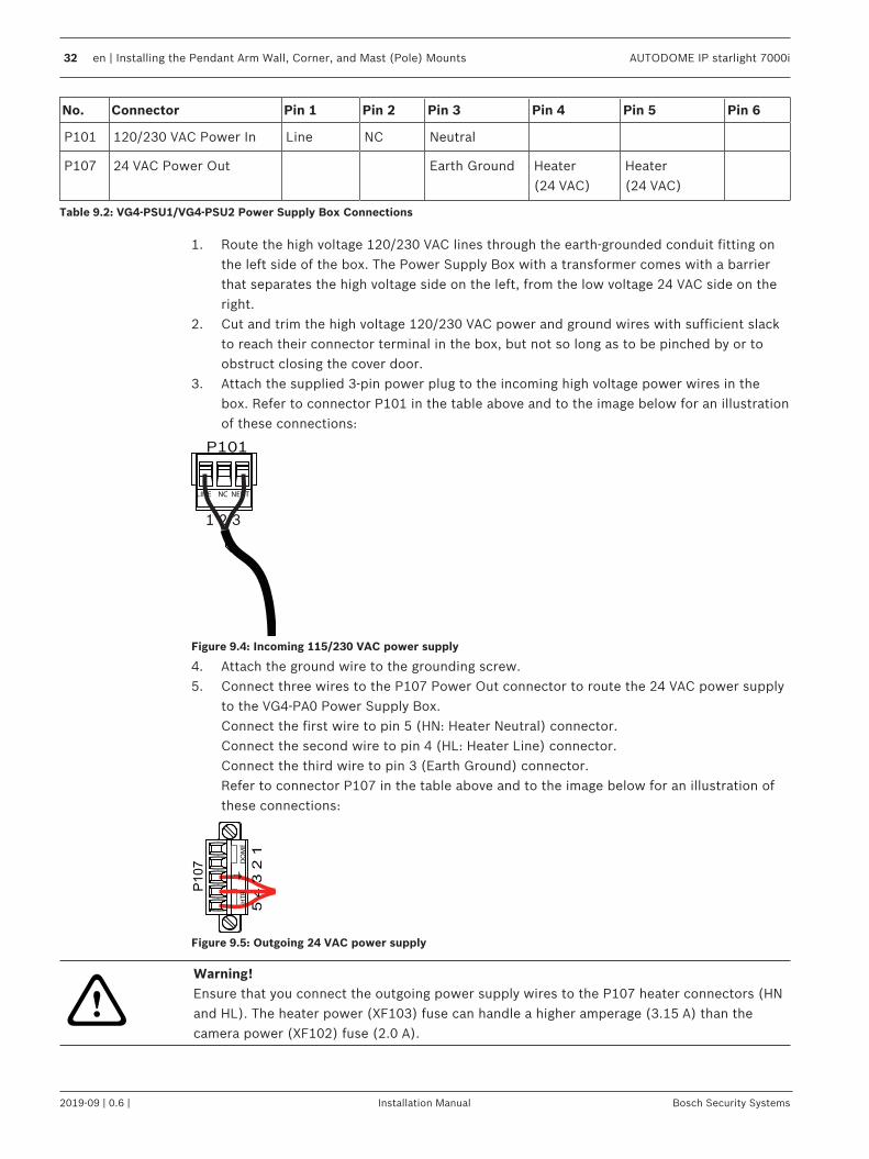
P101 120/230 VAC Power In Line NC Neutral
P107 24 VAC Power Out Earth Ground Heater(24 VAC)
Heater(24 VAC)
Table 9.2: VG4-PSU1/VG4-PSU2 Power Supply Box Connections
1. Route the high voltage 120/230 VAC lines through the earth-grounded conduit fitting onthe left side of the box. The Power Supply Box with a transformer comes with a barrierthat separates the high voltage side on the left, from the low voltage 24 VAC side on theright.
2. Cut and trim the high voltage 120/230 VAC power and ground wires with sufficient slackto reach their connector terminal in the box, but not so long as to be pinched by or toobstruct closing the cover door.
3. Attach the supplied 3-pin power plug to the incoming high voltage power wires in thebox. Refer to connector P101 in the table above and to the image below for an illustrationof these connections:
P101
1 2 3
LINE NC NEUT
Figure 9.4: Incoming 115/230 VAC power supply
4. Attach the ground wire to the grounding screw.5. Connect three wires to the P107 Power Out connector to route the 24 VAC power supply
to the VG4-PA0 Power Supply Box.Connect the first wire to pin 5 (HN: Heater Neutral) connector.Connect the second wire to pin 4 (HL: Heater Line) connector.Connect the third wire to pin 3 (Earth Ground) connector.Refer to connector P107 in the table above and to the image below for an illustration ofthese connections:
P10
7
5 4
3 2
1
HT
R
DO
ME
Figure 9.5: Outgoing 24 VAC power supply
!
Warning!Ensure that you connect the outgoing power supply wires to the P107 heater connectors (HNand HL). The heater power (XF103) fuse can handle a higher amperage (3.15 A) than thecamera power (XF102) fuse (2.0 A).

AUTODOME IP starlight 7000i Installing the Pendant Arm Wall, Corner, and Mast (Pole) Mounts | en 33
Bosch Security Systems Installation Manual 2019-09 | 0.6 |
6. Route the 24 VAC outgoing power supply wires into the VG4-PA0 power supply boxthrough the conduit fitting on the left side of the box.
7. Cut and trim the 24 VAC power and ground wires with sufficient slack to reach theirconnector terminal in the box, but not so long as to be pinched by or to obstruct closingthe cover door.
8. Attach the supplied 3-pin power plug to the incoming 24 VAC power wires in the box, asillustrated below.
GND TXD RXD C+ C-GND TXD RXD C+ C-
P101
1 2 3
6 5 4 3 2 16 5 4 5 4 3 2 16 5 4 5 4 5 4 6 5 4 5 4 6 5 4 5 4 5 4 6 5 4 6 5 4 6 5 4 3 2 1 3 2 16 5 4 3 25 4 3 2 3 25 4 3 2
P106 P105
P10
7
XF
10
2X
F10
3
XF
10
1
5 4
3 2
1
J1
03
J1
03
J1
03
J102
J10
1
(LED)
HT
R D
OM
E
XD
(FU
SE
)(F
US
E)
(FU
SE
)
24V NC 24V
Figure 9.6: VG4-PA0 Power Supply Box
1 Incoming 24 VAC Power Supply Wires (from VG4-PSU1/VG4-PSU2 power supply box)
2 Ground Wire
3 P101 Connector
4 Control Data and Video In/Out Wires (analog models only)
9. Follow the instructions in Attach Pendant Arm to Power Supply Box, page 33 to continue theinstallation.
9.4 Attach Pendant Arm to Power Supply BoxThe bottom hinge pin of the Pendant Arm is provided with a Hinge Pin Stop to hold the hingeopen while attaching the arm to the Power Supply Box.1. Compress the bottom hinge pin by pushing the pin lever downward and rotating it behind
the Hinge Pin Stop.

34 en | Installing the Pendant Arm Wall, Corner, and Mast (Pole) Mounts AUTODOME IP starlight 7000i
2019-09 | 0.6 | Installation Manual Bosch Security Systems
Figure 9.7: Pendant Arm to Power Box Hinge Alignment
2. Open the top hinge by pushing its pin lever up and holding it.
Notice!Both Hinge Pins must be fully compressed to open (unlock) the hinges of the Pendant Armand before proceeding to the next step.
3. While continuing to hold the top hinge pin open and align the top and bottom hinges ofthe Pendant Arm to their mating points on the Power Supply Box. See the illustrationabove.
4. Once you have aligned the hinges, release the top hinge pin to engage its mating hinge onthe power box. Then release the bottom hinge pin from the Hinge Pin Stop to lock thePendant Arm to the Power Supply Box.
!
Warning!Serious injury or death can occur if the hinge pins of the Pendant Arm are not fully engaged(locked) to the Power Supply Box. Exercise caution before releasing the Pendant Arm.

AUTODOME IP starlight 7000i Installing the Pendant Arm Wall, Corner, and Mast (Pole) Mounts | en 35
Bosch Security Systems Installation Manual 2019-09 | 0.6 |
9.5 Make Connections in the Power Supply Box
1 2 3
Figure 9.8: Pendant Arm connections to Power Supply Box
1. Attach the earth ground wire (item 1 in the illustration above) to the grounding screw onthe left side of the power box.
2. Connect the 6-pin Control In/Out Plug, installed previously, to its mating connector P106in the power box.
3. Connect the 6-pin Control to Dome Plug from the Pendant Connector Harness to itsmating connector P105 in the power box.
4. Connect the 5-pin, 24 VAC to Dome Plug from the Pendant Connector Harness to itscorresponding color mating connector P107 on the right side of the box.
5. To connect alarm inputs and relay outputs, connect the 4-pin Alarms Out, the 6-pinAlarms In, and the 7-pin Relay connectors from the Pendant Connector Harness to theirmating connectors, installed previously, to the incoming alarm wires.
6. Connect the 3-pin Power In Plug, installed previously, to its mating connector P101 onthe left side of the box.
7. Connect the incoming RJ45 video connector, installed previously, to its mating connectorfrom the Pendant Connector Harness.
8. Attach the grounding strap of the Pendant Arm to the Power Supply Box.9. After making the harness connections to the Power Supply Box, rotate the Pendant Arm
to close and seal the Power Supply Box and tighten the two (2) captive screws to10‑12 N-m (90-105 in.-lbs).
10. Refer to Attach Pendant to Arm and Tighten, page 39 to continue the installationprocedure.
Notice!After all wiring is complete, close the cover door and tighten the two (2) captive screws onthe cover door to 10-12 N-m (90-105 in.-lbs) to ensure the Power Supply Box is watertight.

36 en | Installing the Pendant Arm Wall, Corner, and Mast (Pole) Mounts AUTODOME IP starlight 7000i
2019-09 | 0.6 | Installation Manual Bosch Security Systems
9.6 Installing the VGA-PEND-WPLATEThis section provides instructions to install a wall, corner, or mast mount with the VGA-PEND-WPLATE Mounting Plate instead of a Power Supply Box.
!
Caution!You must route the main power supply through a 120/230 VAC transformer (VG4-PSU1 orVG4-PSU2 power supply box) before connecting the power to a 24 VAC AUTODOME camera.
!
Warning!A stud diameter of 6.4 mm (1/4 inch) to 8 mm (5/16 inch) able to withstand a 120 kg (265 lb)pull-out force is recommended. The mounting material must be able to withstand this pull outforce. For example, 19-mm (3/4-inch) minimum for plywood.
1. For a Corner installation:Secure the Corner Plate to the wall corner using four (4) studs (not included).Secure the Mounting Plate to the Corner Plate using the four (4) 3/8 x 1-3/4-inch boltsand split lock washers (supplied).
2. For a Mast or pole installation:The metal straps included with the Mast mount accommodate a pole with a diameter of100–380 mm (4–15 in.). You must use a banding tool (sold separately) for a mast or poleinstallation. In addition, you must obtain a 3/4 in. (20-mm) right angle conduit connectorthrough which you route the wires that connect to the pendent arm. Follow the instructions provided with the banding tool to securely mount the Mast Plateto the pole. Contact your Bosch Sales Representative to order Banding Tool P/NTC9311PM3T.Secure the Mounting Plate to the Mast Plate using the four (4) 3/8 x 1-3/4-inch bolts andsplit lock washers (supplied).Remove one of the rubber gaskets from the Mounting Plate.Once the Mounting Plate (item 1, below) is attached to the Mast Plate (item 2), connectthe right angle conduit (item 3) to the Mounting Plate through the empty conduit hole asshown below:
3. Ensure that the mounting plate is secure.

AUTODOME IP starlight 7000i Installing the Pendant Arm Wall, Corner, and Mast (Pole) Mounts | en 37
Bosch Security Systems Installation Manual 2019-09 | 0.6 |
Attach the Pendant Arm to the Mounting PlateThe bottom hinge pin of the Pendant Arm is provided with a Hinge Pin Stop to hold the hingeopen while attaching the arm to the Mounting Plate.1. Compress the bottom hinge pin by pushing the pin lever downward and rotating it behind
the Hinge Pin Stop.
Figure 9.9: Connect Pendant Arm to Mounting Plate
2. Open the top hinge by pushing its pin lever up and holding it.Note: Both Hinge Pins must be fully compressed to open (unlock) the hinges of thePendant Arm and before proceeding to the next step.
3. While continuing to hold the top hinge pin open, align the top and bottom hinges of thePendant Arm to their mating points on the Mounting Plate.
4. Once you have the hinges aligned, release the top hinge pin to engage its mating hinge onthe Mounting Plate. Then release the bottom hinge pin from the Hinge Pin Stop to lockthe Pendant Arm to the Mounting Plate.
Route and Connect Wires to a Power Supply BoxThe illustration below depicts the power and control cables connected to the Pendant Arm:
Figure 9.10: Pendant Arm Cables
Cable Cable
1 Grounding Strap (black) 5 UTP Video/Ethernet (blue)

38 en | Installing the Pendant Arm Wall, Corner, and Mast (Pole) Mounts AUTODOME IP starlight 7000i
2019-09 | 0.6 | Installation Manual Bosch Security Systems
2 24 VAC Power (red) 6 Alarm Outputs (white)
3 Relay Contacts (yellow) 7 Alarm Inputs (gray)
4 Coax Video (black) (Not applicable for AUTODOME7000 Series cameras)
8 Serial Communications (green)Used for Audio Input/Output inAUTODOME 7000 Series.
Notice!Refer to the Connection, page 56 chapter for wire specifications and distances.
1. Route all incoming wires through one of the earth-grounded conduits at the bottom of theMounting Plate. For a mast mount, route all wires through the right-angle conduit.
2. Attach the water-tight plug to the other conduit.3. Attach the grounding spade terminal (item 1, below) to one of the spade terminals inside
the Mounting Plate.
Figure 9.11: Mounting Plate - Inside Detail
Ref. Description
1 Grounding lug with two spade terminals
2 Earth ground lug with crimp ring terminal
3 Wire input conduit holes
4. Connect the incoming 24 VAC power wires to the 5-pin, 24 VAC Power In matingconnector (supplied with the Mounting Plate kit) for the camera and for the Heater.

AUTODOME IP starlight 7000i Installing the Pendant Arm Wall, Corner, and Mast (Pole) Mounts | en 39
Bosch Security Systems Installation Manual 2019-09 | 0.6 |
5. Attach the grounding spade from the 5-pin mating connector to the other spade terminalinside the mounting plate.
6. Attach the 5-pin Power In mating connector to the 24 VAC Power cable (cable 2)connected to the pendant.
7. Remove the mating connector from the Relay Contacts cable (cable 3).8. Connect the incoming relay contact wires to the mating connector. Then, reattach the
mating connector to the Relay Contacts cable.9. Attach an RJ45 plug to the incoming UTP cable.10. Connect the incoming RJ45 video connector, installed previously, to the UTP Video/
Ethernet cable (cable 5).11. Connect the outgoing alarm wires to the flying leads coming from the 4-pin Alarm
Outputs cable (cable 6).12. Connect the incoming alarms wires to the flying leads coming from the 6-pin Alarm Inputs
cable (cable 7).13. Connect the incoming serial communication wires to the 6-pin mating connector supplied
with the VGA-PEND-WPLATE kit. Refer to the Power Supply Box Connections table abovefor details.
14. Attach the 6-pin serial communication mating connector to the Serial Communicationscable (cable 8).
15. Connect the Earth ground wire, if available, to the crimp ring terminal inside theMounting Plate.Note: The Earth ground is not provided with the VGA-PEND-WPLATE kit; it is a groundconnection made at the installed location.
16. After making the harness connections to the Mounting Plate, rotate the Pendant Arm toclose and tighten the two (2) captive screws to 10‑12 N-m (90-105 in.-lbs).
Notice!After all wiring is complete, close the cover door and tighten the two (2) captive screws onthe cover door to 10-12 N-m (90-105 in.-lbs).
9.7 Attach Pendant to Arm and Tighten
Notice!Before attaching the AUTODOME Pendant, visually inspect the dome and arm connectors forany blocked pin holes or bent pins.
1. Tilt the bottom of the dome toward the pendant arm base and place the mounting hook,located on top of the dome housing, over the recessed hinge pin of the arm.

40 en | Installing the Pendant Arm Wall, Corner, and Mast (Pole) Mounts AUTODOME IP starlight 7000i
2019-09 | 0.6 | Installation Manual Bosch Security Systems
a
b
Figure 9.12: Attach Pendant to Arm
1 Tilt up.
2 Hook and drop.
2a Recessed Hinge Pin
2b Dome Connector
3 Rotate down to engage dome connector.
4 Tighten the two (2) mounting screws to a minimum torque of 10-12 N-m (90-105 in.-lbs).
2. Drop the dome housing down slightly to engage the dome housing hook on the PendantArm hinge pin, allowing the dome to rotate around the pin.
3. Rotate the dome housing down to a vertical position and gently push upward to engagethe connector on top of the dome housing.
!
Caution!If you feel any resistance when rotating the dome housing or when engaging the connector,stop immediately and start over.
4. Hold the Pendant housing in position while tightening the two (2) 5-mm Allen headmounting screws on top of the housing to 10-12 N-m (90-105 in.-lbs).
!
Caution!You must tighten the two mounting screws to a minimum torque of 10-12 N-m (90‑105 in.-lbs)to ensure a proper seal between the arm and the housing.

AUTODOME IP starlight 7000i Installing the Roof Parapet and Pipe Mounts | en 41
Bosch Security Systems Installation Manual 2019-09 | 0.6 |
10 Installing the Roof Parapet and Pipe Mounts10.1 Description
This chapter details how to install an AUTODOME camera to a Roof Parapet or to a Pipemount. Any differences to the installation between these two mounting systems are noted.The VGA-ROOF-MOUNT is a stationary mount intended for rooftop parapet vertical walls. It ismade of light weight aluminum with a corrosion-resistant finish and is used for all BoschAUTODOME cameras up to a rated load of 29 kg (64 lb). This mount can be fitted to the insideor outside of parapet walls and can swivel for ease of positioning and for servicing the camera.Note that customers must purchase separately the VG4-A-9543 Pipe Mount to use on the endof the VGA-ROOF-MOUNT.The end of the Pipe Mount that is meant to terminate into an enclosure is intended to be field-installed and shall be marked or provided with instructions that identify the equipmentnecessary to maintain the environmental integrity of the enclosure. In order to maintain theintegrity of a Type 4X environment, the connected equipment must have a Type 4Xenvironmental rating. In order to maintain the integrity of a Type 4 environment, theconnected equipment must have a Type 4, Type 4X, Type 6, or Type 6P environmental rating.
10.2 Route Wires and Attach ConnectorsPower wires must be routed to the left (front) side of the Power Supply Box through aseparate electrically earth-grounded conduit. All video, control, and alarm wires must berouted through a second electrically earth-grounded conduit to the right side of the box.
!
Warning!External interconnecting cables are to be installed in accordance to NEC, ANSI/NFPA70 (forUS application) and Canadian Electrical Code, Part I, CSA C22.1 (for CAN application) and inaccordance to local country codes for all other countries.Branch circuit protection incorporating a 20 A, 2-pole Listed Circuit Breaker or Branch RatedFuses are required as part of the building installation. A readily accessible 2-pole disconnectdevice with a contact separation of at least 3 mm (0.12 in.) must be incorporated.
There are two possible methods to route the video, control, and alarm wires:Method One is to route the video, control, and alarm wires through the conduit fitting on theright (front) side of the Power Supply Box and out to the AUTODOME Interface Board.

42 en | Installing the Roof Parapet and Pipe Mounts AUTODOME IP starlight 7000i
2019-09 | 0.6 | Installation Manual Bosch Security Systems
GND TXD RXD C+ C-GND TXD RXD C+ C-
P101
P106 P105
P1
07
XF
10
2X
F1
03
XF
10
1
5 4
3 2
1
J1
03
J1
03
J1
03
J102
J10
1
(LED)
HT
R
DO
ME
(FU
SE
)(F
US
E)
(FU
SE
)(F
US
E)
LINE NC NEUT
Figure 10.1: VG4-A-PSU1 or VG4-A-PSU2 Power Supply Box
1 120 VAC/230 VAC Power In 6 Control WireUsed for Audio input and output inAUTODOME 7000 Series.
2 P101 Connector 7 24 VAC Power Out
3 Ground Connection 8 P107 Connector
4 Transformer 9 Earth-grounded conduit with power inputand earth-ground connection
5 Ethernet Wire 10 Earth-grounded conduit with Ethernetvideo/control, audio input and output to“head-end“ system
11 Earth-grounded conduit to camera
Wiring the Power Supply Box
Notice!Refer to the Connection, page 56 chapter for wire specifications and distances.
4 Route the high voltage 115/230 VAC lines through the earth-grounded conduit fitting onthe left side of the box.

AUTODOME IP starlight 7000i Installing the Roof Parapet and Pipe Mounts | en 43
Bosch Security Systems Installation Manual 2019-09 | 0.6 |
Notice!The Power Supply Box with transformer comes with a barrier that separates the high voltageside on the left from the low voltage 24 VAC side on the right.
1. Cut and trim the high voltage 115/230 VAC power and ground wires with sufficient slackto reach their connector terminal in the box, but not so long as to be pinched by or toobstruct closing the Cover Door.
2. Attach the supplied 3-pin Power Plug to the incoming high voltage power wires in thebox. Refer to connector P101 in the Power Supply Box Connections section below.
3. Route the Ethernet cable out to where the camera will be mounted.4. Route the low power 24 VAC wires from the right side of the Power Supply Box out to
where the camera will be mounted. Attach the supplied 5-pin 24 VAC Dome plug to thewire ends inside the box. Refer to connector P107 in the Power Supply Box Connectionssection below.
Wiring the Fiber Optic ModelIf installing a Fiber Optic model, follow these steps:
Notice!Refer to the Connection, page 56 chapter for fiber optic specifications.For instructions on installing a fiber optic module into a power supply box, see the VG4 FiberOptic Media Converter Installation Guide that ships with the module.
1. Bring the fiber optic cable (item 3 in the figure below) into the right side of the powersupply box.
2. Connect the fiber optic cable to the port for the SFP module (item 2 in the figure below).3. Connect the RJ45 plug of the cable to the RJ45 socket (item 1 in the figure below) on the
fiber optic module in the power supply box.4. Route the control wires from the Power Supply to the Pipe Interface Board. Then attach
the supplied six (6) pin control data connector to the wires in the Power Supply Box.Refer to Wire the Pipe Interface Board, page 48.

44 en | Installing the Roof Parapet and Pipe Mounts AUTODOME IP starlight 7000i
2019-09 | 0.6 | Installation Manual Bosch Security Systems
GND TXD RXD C+ C-
P101
P106
XF
10
2X
F1
03
XF
10
1
5 4
3 2
1
J1
03
J1
03
J1
03
J102
J10
1
(LED)
HT
R D
OM
E
24V NC 24V
(FU
SE
)(F
US
E)
(FU
SE
)(F
US
E)
Figure 10.2: Fiber Optic Ethernet Module installed
1 RJ45 Ethernet socket
2 Port for SFP module (sold separately)
3 Fiber Optic cable (user-supplied)

AUTODOME IP starlight 7000i Installing the Roof Parapet and Pipe Mounts | en 45
Bosch Security Systems Installation Manual 2019-09 | 0.6 |
Power Supply Box ConnectionsThe following figure is a detailed illustration of the Roof or Pipe Mount Power Supply Box,which includes the fuse specifications.
CONTROL
TO DOMEO DOMO DOM
CONTROL
IN/OUT
GND GND GND TXD
RXD
C+
C-
P101
1 2 3
6 5 4 3 2 16 5 4 3 2 1
P106 P105
P1
07
XF1
02
XF1
03
XF1
01
5 4
3 2
1
J1
03
J1
03
J1
03
J1
03
J102J102J102J102
J1
01
J1
01
J1
01
J1
01
J1
01
J1
01
J1
01
J1
01
J1
01
J1
01
J1
01
J1
01
J1
01
J1
01
J1
01
J1
01
J1
01
J1
01
J1
01
J1
01
J1
01
J1
01
J1
01
J1
01
J1
01
J1
01
J1
01
J1
01
J1
01
J1
01
J1
01
J1
01
J1
01
J1
01
J1
01
J1
01
J1
01
J1
01
J1
01
J1
01
J1
01
(LED)
6 5 4 3 2 1
GND GND GND TXD RXD C+ C- XD XD XD XD
HT
R D
OM
E
(FU
SE
)(F
US
E)
(FU
SE
)(F
US
E)
(FU
SE
)(F
US
E)
(FU
SE
)(F
US
E)
(FU
SE
)(F
US
E)
(FU
SE
)
(FU
SE
)(F
US
E)
(FU
SE
)(F
US
E)
(FU
SE
)(F
US
E)
(FU
SE
)(F
US
E)
(FU
SE
)
LINE NC NEUT
Figure 10.3: Power Supply Box Connections
1 Ground Screw 5 Power In
2 Transformer (115/230 VAC Modes) 6 In/Out; 1/2 in. (15 mm) NPS Fitting
3 In/Out to camera 7 Power In; 3/4 in. (20 mm) NPS Fitting
4 24 VAC to Dome Interface Board 8 Control Data and Video In/Out; 3/4 in. (20 mm)NPS Fitting
!
Warning!Fuse replacement by qualified service personnel only. Replace with same type fuse.
Fuse Specifications
Volts XF101 Mains XF102 Camera XF103 Heater
24 V T 5.0 A T 2.0 A T 3.15 A
115 V T 1.6 A T 2.0 A T 3.15 A
230 V T 0.8A T 2.0 A T 3.15 A
The following table lists the Power Supply Box connectors:
No. Connector Pin 1 Pin 2 Pin 3 Pin 4 Pin 5 Pin 6
Ground Grounding Screw

46 en | Installing the Roof Parapet and Pipe Mounts AUTODOME IP starlight 7000i
2019-09 | 0.6 | Installation Manual Bosch Security Systems
No. Connector Pin 1 Pin 2 Pin 3 Pin 4 Pin 5 Pin 6
P101 115/230 VAC or24 VAC Power In
Line NC Neutral
P107 24 VAC Power toDome Plug
Dome24 VAC
Dome24 VAC
Earth Ground Heater(24 VAC)
Heater(24 VAC)
10.3 Attach Cover Door to Power Supply Box1. Compress the bottom hinge pin by pushing the pin lever down and then rotate it behind
the Hinge Pin Stop. The power box Cover Door provides a Hinge Pin Stop to hold thebottom hinge open while attaching the door.
GND T XD R XD C+ C- GND T XD R XD C+ C-
(FU
SE
) (F
US
E)
(FU
SE
)
90o
HT
R
DO
ME
LINE NC NEUT
Figure 10.4: Align Cover Door Hinge to Power Box
1 Power Supply Box 5 Hold Hinge Pin Open
2 Cover Door 6 Open Position
3 Align Top Hinge 7 Hinge Pin Stop
4 Align Bottom Hinge
2. Open the top hinge by pushing its pin lever outward and holding it open.Note: Both Hinge Pins must be fully compressed to open (unlock) the female hinges ofthe Cover Door before proceeding to the next step.
3. While holding the top hinge pin open, position the Cover Door to the Power Supply Boxand align its hinges.
4. When the hinges are aligned, release the top hinge pin to engage its mating hinge on thepower box. Then release the bottom hinge pin from the Hinge Pin Stop to completeattaching the Cover Door to the Power Supply Box.

AUTODOME IP starlight 7000i Installing the Roof Parapet and Pipe Mounts | en 47
Bosch Security Systems Installation Manual 2019-09 | 0.6 |
Notice!After all wiring is complete, close the cover door and tighten the two (2) captive screws onthe cover door to 10-12 N-m (90-105 in.-lbs) to ensure the Power Supply Box is watertight.
10.4 Installing the VG4-A-9543 Pipe MountThis section details the installation steps for the VG4-A-9543 Pipe Mount. If you are installingthe Roof Parapet mount, refer to Installing the VG4-ROOF-MOUNT for instructions.
Notice!Customer must supply 1-1/2 inch (NPS) pipe threaded on both ends with a minimum lengthof 5 inches (12.7 cm).You must use Teflon tape for thread-sealing compound.All screws shall be tightened securely.
5 in.
12.7 cmmin.
Figure 10.5: Pipe Mount
1 Gasket
2 Flange
3 Cap
1. Before installing the Top-Mounting Flange, ensure there is an adequate opening in theceiling or mounting structure for the wires to pass through.
2. Secure the pipe Flange with supplied gasket to the ceiling or other supporting structureusing four (4) 10-mm (3/8-inch) diameter fasteners.
Notice!Each fastener must have a minimum pullout strength of 275 kg (600 lbs). The mountingmaterial must be able to withstand this pull-out force. For example, 19-mm (3/4-inch)minimum for plywood.
3. Attach pipe (not supplied) to the Top-mounting Flange.
!
Warning!You must thread the pipe onto the Top-mounting Flange until it is tight. Failure to do so canresult in damage, serious injury or death.
4. Route the power, video, control, and alarm wires through the Top-Mounting Flange anddown the pipe.
5. Wrap at least five layers of Teflon tape around the threads.

48 en | Installing the Roof Parapet and Pipe Mounts AUTODOME IP starlight 7000i
2019-09 | 0.6 | Installation Manual Bosch Security Systems
6. Apply the supplied thread sealant to the threads on the Pipe.Make sure all surfaces are clean and dry.Apply a bead of sealant completely around the leading threads of the male fitting.Force the adhesive into the threads to thoroughly fill all voids.
7. Thread the Pipe Cap onto the down pipe and tighten securely to prevent leaks.
!
Warning!You must thread the Dome Cap onto the pipe until it is tight. Failure to do so can result indamage or serious injury or death.
10.5 Wire the Pipe Interface BoardThis section provides instructions for connecting wires and cables to the Pipe Interface Board,as illustrated below. Refer to the Connection, page 56 chapter for cable and wiringrecommendations and specifications.
BNC
7
5
6
4
3
2
1
2
1
2
1
3
J1
02
P1
07
P1
01
P1
02
P1
03
P1
04
P106
J101
AGNDA7A6A5A4A3
AGND
OUT 3
OUT 2
OUT 1
1
2
3
4
5
6
P1
05
Figure 10.6: Pipe Interface Board Connections

AUTODOME IP starlight 7000i Installing the Roof Parapet and Pipe Mounts | en 49
Bosch Security Systems Installation Manual 2019-09 | 0.6 |
Ref. Description Connector WireGauge
Pin Description
1 Pipe InterfaceModule
2 Video Coax In J102
3 6-pin ConnectorAlarms In (3-7)
P103
4 4-pin ConnectorAlarms Out (1-3)
P102
5 100 Ω ResistorNote: Whenusing the audioinput in anAUTODOME7000 Seriescamera, removethis resistor.
P105
6 Data In/Out P105 AWG26-16
1 Biphase (C-)For AUTODOME 7000 Series: AUDIO IN– (Audio in signal ground)
2 Biphase (C+)For AUTODOME 7000 Series: AUDIO IN+
3 Earth Ground
4 RxD +For AUTODOME 7000 Series: AUDIOOUT +
5 TxD –For AUTODOME 7000 Series: AUDIOOUT – (Audio out signal ground)
6 Signal Ground
7 Alarms In (EOLRSupervised, 1-2)
P104 AWG26-16
7 Ground
6 Alarm 2
5 Alarm 1
4 Earth Ground
8 Relay Output P104 AWG26-16
3 Normally Closed
2 Common
1 Normally Open
9 Dome Power P101 AWG18-14
3 Dome 24 VAC
2 Earth Ground

50 en | Installing the Roof Parapet and Pipe Mounts AUTODOME IP starlight 7000i
2019-09 | 0.6 | Installation Manual Bosch Security Systems
Ref. Description Connector WireGauge
Pin Description
1 Dome 24 VAC
10 Heater Power P107 AWG18-14
2 Heater 24 VAC
1 Heater 24 VAC
11 RJ45 Ethernet J101
12 To camera
The Pipe Interface Board contains all of the connectors for control, data, image, and powerwires. Follow the procedures below to make the proper connections.
!
Warning!Use a 24 VAC Class 2 power supply only.
1. Attach an RJ45 connector plug to the Ethernet cable and connect the plug to its matingconnector J101 on the Pipe Interface Board.
2. Attach the control data in/out wires to their respective terminals on the P105 connectoron the Pipe Interface Board.
3. Connect the 24 VAC power wires to the P101 connector on the Pipe Interface Board. Ifthis model has a heater, connect the 24 VAC heater power wires to connector P107.
!
Caution!To protect the camera from damage due to cold temperatures, ensure that you connect the24 VAC heater power wires to the P101 connector.
Connecting Alarm Inputs and Outputs4 To connect alarm inputs and outputs, attach the supplied 6-pin Alarms In and the 4-pin
Alarms Out connector plugs with flying lead wires to the appropriate incoming alarmwires. Alarm Out 4 is a relay.
1
1
2
3
4
5
6
2
3
4 N.O
. CO
M
N
.C.
A
1
GN
D A2
1
PIN
PIN
P102
P103
P104
WHITE
ORANGE
BROWN
GREEN
WHITE
ORANGE
BROWN
GREEN
YELLOW
BLUE
2
3
4
5
6
7
Figure 10.7: Alarm and relay connectors
1 4-pin AlarmConnector (P102)
2 6-pin Alarm InConnector (P103)
3 7-pin Relay Connector (P104)

AUTODOME IP starlight 7000i Installing the Roof Parapet and Pipe Mounts | en 51
Bosch Security Systems Installation Manual 2019-09 | 0.6 |
Pin Description Pin Description Pin Description
1 Alarm Out 1 1 Alarm in 3 1 Alarm Out 4 Normally Open
2 Alarm Out 2 2 Alarm in 4 2 Alarm Out 4 COM
3 Alarm Out 3 3 Alarm in 5 3 Alarm Out 4 Normally Closed
4 Alarm Ground 4 Alarm in 6 4 Earth Ground
5 Alarm in 7 5 Analog Alarm 1
6 Alarm Ground 6 Analog Alarm 2
7 Ground
For in-ceiling mount only: Low Voltage TTL (3.3V) can also be used.
4 Connect the plugs to their mating connectors P103 and P102 on the Pipe InterfaceBoard.
1. To connect supervised alarms and relays, attach the appropriate wires to their terminalson the P104 connector on the Pipe Interface Board (see above).
2. Insert the Pipe Interface Board into the down pipe and fasten the three (3) retainingscrews to secure the board to the Dome Cap.
!
Caution!Be careful not to strip the threads when tightening the Pipe Interface Board retaining screws.
Figure 10.8: Pipe Interface Board to Dome Cap Assembly
1 Interface Board
2 Retaining Screws (3)
3 Pendant Mounting Screws (2)

52 en | Installing the Roof Parapet and Pipe Mounts AUTODOME IP starlight 7000i
2019-09 | 0.6 | Installation Manual Bosch Security Systems
10.6 Attach Pendant to Pipe and Tighten1. Before attaching the Pendant, visually inspect the Pendant dome and the Interface Board
connectors for any blocked pin holes and bent pins.2. Tilt the Pendant enough to place its mounting hook on top of the its housing, over the
recessed hinge pin of the Dome Cap.
a
b
c
Figure 10.9: Pendant to Roof / Pipe Mount Attachment
1 Tilt Dome
2 Hook and drop
2a Dome Cap
2b Recessed Hinge Pin
2c Dome Connector
3 Rotate down to engage dome connector
4 Tighten the two (2) mounting screws to a minimum torque of 10-12 N-m (90-105 in.-lbs)
3. Drop the Pendant down slightly to engage the dome hook and hinge pin of the Dome Cap,allowing the dome to rotate around the hinge pin.
4. Rotate the dome housing down to a vertical position and gently push upward to engagethe connector on top of the dome housing.
!
Caution!If you feel any resistance when rotating the dome housing or when engaging the connector,stop immediately and start over.
5. Hold the housing firmly in position and alternately tighten the two (2) 5-mm Allen headmounting screws from above to a torque value of 10-12 N-m (90-105 in.-lbs).

AUTODOME IP starlight 7000i Installing the Roof Parapet and Pipe Mounts | en 53
Bosch Security Systems Installation Manual 2019-09 | 0.6 |
!
Caution!You must tighten the two mounting screws to a minimum torque of 10-12 N-m (90‑105 in.-lbs)to ensure a proper seal between the arm and the housing.
6. Rotate the arm to swing the camera out from the roof and into position, if installing aParapet Roof Mount.
7. Tighten the three (3) 10-mm (3/8-inch) stainless steel hex bolts on the bracket to lock theParapet Arm in position.
!
Caution!Do not over tighten the bolts. The maximum torque is 34 N-m (25 ft-lb).
10.7 Make Connections in the Power Supply Box1. Attach the earth ground wire to the grounding screw on the left side of the box.2. Connect the 24 VAC to Dome plug, installed previously, to its mating connector P107 on
the right side of the box.3. Connect the 115/230 VAC, 3-pin Power-in plug, installed previously, to its mating
connector P101 on the left side of the box.

54 en | Finalizing installation AUTODOME IP starlight 7000i
2019-09 | 0.6 | Installation Manual Bosch Security Systems
11 Finalizing installationRemove the plastic on the bubbleAfter you complete all other installation steps, remove the plastic material that is protectionfor the bubble.

AUTODOME IP starlight 7000i Replacing a Pendant Bubble | en 55
Bosch Security Systems Installation Manual 2019-09 | 0.6 |
12 Replacing a Pendant Bubble1. Using both hands, apply a firm counterclockwise (looking up at the dome) rotational forceon the pendant bubble assembly to set the bubble latch.2. Insert a small (2 mm) straight blade screw driver into the release opening in the bubble trimring to release the lock, and then remove the screwdriver.
Figure 12.1: Pendant Bubble Release Opening
3. Firmly rotate the bubble counterclockwise approximately 20 degrees until the bubbleassembly releases from the pendant housing.4. Locate the four tabs (item 1, below) inside the trim ring that attach the trim ring to thebubble.5. Gently push each tab out and down (away from the bubble) to disengage the tabs.6. Remove the bubble from the trim ring.
7. Insert the replacement bubble inside the trim ring and align the release tab (item 2, above)on the trim ring with the release slot on the bubble.8. Clean the bubble according to the instructions in the section “Maintenance.”9. Insert the replacement bubble and trim ring assembly into the pendant housing, and rotateit clockwise until it locks. The latch mechanism makes a click when locks.
56 en | Connection AUTODOME IP starlight 7000i
2019-09 | 0.6 | Installation Manual Bosch Security Systems
13 Connection13.1 Connecting the AUTODOME camera to the PC
1. Install the camera according to the instructions in the appropriate Installation section ofthis manual.
2. Connect an Ethernet cable from camera’s RJ45 connector to a dedicated network switchto bypass the Local Area Network (LAN).
3. Connect the dedicated network switch to the RJ45 connector on the PC (see option Abelow).
Notice!The camera can also be connected directly to a PC using an Ethernet crossover cable withRJ45 connectors (see option B below).
1
2
3 41
2
2
4
Figure 13.1: AUTODOME 7000 Series System Configuration
1 AUTODOME 7000 Series
2 IP Connection
3 Network Switch
4 Computer
Notice!You can also use the Bosch Video Client software application to configure the networksettings for an AUTODOME 7000 Series camera. Go to www.boschsecurity.com to downloadthe Configuration Manager software and Operating Manual.
13.2 Power Cable and Wire Distances GuidesPower
115/230 VAC
Copper Wire To comply with local codes.
!
Caution!Compliance with EN50130-4 Alarm Standard – CCTV for Security ApplicationsTo meet the requirements of the EN50130-4 Alarm Standard, an ancillary uninterruptablepower (UPS) supply is necessary. The UPS must have a Transfer Time between 2–6 ms and aBackup Runtime of greater than 5 seconds for the power level as specified on the productdatasheet.

AUTODOME IP starlight 7000i Connection | en 57
Bosch Security Systems Installation Manual 2019-09 | 0.6 |
Maximum Wire Distances from Power Supply to AUTODOME
24 V to AUTODOME
VA / Watts 14 AWG(2.5 mm)
16 AWG(1.5 mm)
18 AWG(1.0 mm)
HD models with IVA, Outdoor 60 / 55 58 m (190 ft) 36 m (119 ft) 23 m (75 ft)
Maximum Wire Distances from Power Supply to AUTODOME 7000 HD
24 V to AUTODOME 7000
VA / Watts 14 AWG (2.5 mm)
16 AWG (1.5 mm)
18 AWG (1.0 mm)
HD models with IVA, Indoor 35 / 19 99 m (325 ft) 62 m (205 ft) 39 m (129 ft)
HD models with IVA, Outdoor 60 / 55 58 m (190 ft) 36 m (119 ft) 23 m (75 ft)
13.3 Ethernet ConnectionsThe camera connects to a 10 Base-T/100 Base-TX network either directly or via a hub. Video,optional audio input, optional audio output, and control are transmitted over a standard TCP/IP network using the built-in Web server. In addition, power can be supplied over the Ethernetcable using the Bosch High PoE 60W midspan (sold separately). Power can also be suppliedover the Ethernet cable to in-ceiling models and indoor/outdoor pendant models used inindoor applications (where the heater is not powered) using PoE+ PSEs (midspan switches)compliant with the IEEE 802.3at, class 4 standard.The camera can be connected simultaneously to a 24 VAC power supply and to a High PoE 60W midspan. The camera uses power from the 24 VAC power supply. If this power supply fails,the camera seamlessly switches power input to the High PoE 60 W midspan. The cameraswitches back to the 24 VAC power supply once power is restored.Refer to Using the IP Interface, for instructions on configuring an IP environment.
!
Warning!BOSCH High PoE or PoE+ (802.3at): Use only approved High PoE or PoE+ (802.3at) devices.For outdoor pendant applications that require heater power use only the Bosch High PoEmidspan (sold separately) to power the camera and the heaters. For in-ceiling or indoorpendant applications that don't require heater power, standard PoE+ (802.3at) midspans orswitches can be used to power the camera.When powering the camera via PoE or a midspan device, additional surge protection isrequired.If auxiliary power (24VAC camera and 24VAC heater) and High PoE are appliedsimultaneously, the camera selects the auxiliary 24VAC input and draws minimal power fromthe High PoE midspan.
!
Caution!Ethernet CAT 5E/CAT 6 cables must be routed through earth-grounded conduit for indoor oroutdoor applications. For outdoor applications, the conduit should be capable ofwithstanding the outdoor environment.

58 en | Connection AUTODOME IP starlight 7000i
2019-09 | 0.6 | Installation Manual Bosch Security Systems
Notice!The heater in an outdoor AUTODOME unit cannot be powered via the Power-over-Ethernet +(IEEE 802.3at, class 4) standard, unless the heater is connected to a High PoE Midspan 60W,Single port (sold separately). See the Installation Manual of the Midspan for details.
Cable Type CAT-5E or CAT 6 Ethernet
Maximum Distance 100 m (328 ft)
Bandwidth 10 Base-T/100 Base-TX
High PoE (required for pendants in outdoor applications that useheaters)
Use the Bosch High PoE 60W midspan(sold separately).
PoE+ (only for indoor models or indoor applications for pendant modelwhere heater is not required)
IEEE 802.3at, class 4 standard
Terminal Connector RJ45, Female
Notice!Consult the National Electrical Code (NEC) for cable bundling requirements and limitations.
13.4 Fiber Optic Ethernet Media Converter (Optional)The fiber optic media converter is designed to transmit 10/100 Mbps Ethernet signals overfiber optic cable using 10/100 Mbps Small Form-factor Pluggable (SFP) modules. The SFPmodules are available as multi-mode fiber (MMF) or single-mode fiber (SMF) models with asingle SC connector or dual-fiber with an LC connector. Refer to the VG4-SFPSCKT Fiber OpticMedia Converter Installation Guide.
Ethernet Media Converter
Data Interface Ethernet
Data Rate 10/100 MbpsIEEE 802.3 CompliantFull Duplex or Half Duplex Electrical PortFull Duplex Optical Port
Fiber Type, MMF 50/125 µm MMF. For 50/125 µm fiber, subtract 4 dB from the specified optical budgetvalue. Must meet or exceed fiber standard ITU-T G.651.
Fiber Type, SMF 8–10/125 µm SMF. Must meet or exceed fiber standard ITU-T G.652.
Maximum Distance 20 km (12.4 miles)
Requirement Media converter receiver (CNFE2MC/IN) at controller end of system
Terminal Connection Duplex LC or Single SC

AUTODOME IP starlight 7000i Connection | en 59
Bosch Security Systems Installation Manual 2019-09 | 0.6 |
13.5 Alarms and Relay ConnectionsAlarm InputsThe camera provides seven alarm inputs. Each input can be activated by dry contact devicessuch as pressure pads, passive infra-red detectors, door contacts, and similar devices. Thetable below summarizes the size and distance wires.
Wire Size Maximum Distance
AWG mm feet meters
22 0.644 500 152.4
18 1.024 800 243.8
Tab. 13.3: Alarm wire guide
You wire alarms either Normally Open (N.O.) or Normally Closed (N.C.), and must program thealarm inputs N.O. (the default) or N.C. through the page Configuration.The camera incorporates two types of alarms: Non-supervised and Supervised. In addition totransmitting an alarm condition, a supervised alarm also transmits a tamper condition.Depending on how the alarm is configured, a short or a break in the alarm’s circuit can triggerthe tamper signal.
Configuring Supervised Alarms (inputs 1 and 2)To configure Alarm 1 or 2 (pin 5 or 6) for supervision, you must install a 2.2 K end-of-lineresistor in the circuit. Then, you program the alarms, through Configuration, to eitherNormally Open (N.O.) or Normally Closed (N.C.).
Notice!Only Alarms 1 and 2 (pins 5 or 6) can be configured for supervision. Once a supervised alarmis programmed, it does not need to be enabled to indicate a tamper condition.
Configuring a Normally Open Supervised Alarm1. Install a 2.2 K end-of-line resistor in the alarm circuit.2. Connect the alarm wires to input 1 or 2 (pin 5 or 6) and to the ground (pin 7) at the
camera.
2.2K
Figure 13.2: N.O.S. - Normally Open Supervised Connections
1 Dry Contact 3 Dome Connector
2 Alarm 1 or 2 only (Pin 5 or 6) 4 Ground (Pin 7)
3. From Configuration, select Interfaces > Alarm Inputs, select the number of the Alarminput and finally, select N.O. See the table below for contact and condition details.

60 en | Connection AUTODOME IP starlight 7000i
2019-09 | 0.6 | Installation Manual Bosch Security Systems
AUTODOME Programmed N.O.S.
Contact Alarm Condition
Open Normal
Closed Alarm
Cut or break Tamper
Configuring a Normally Closed Supervised Alarm1. Install a 2.2 K end-of-line resistor in the alarm circuit.2. Connect the alarm wires to input 1 or 2 (pin 5 or 6) and to the ground (pin 7) at the
camera.
2.2K
Figure 13.3: N.C.S. - Normally Closed Supervised Connections
1 Dry Contact 3 Dome Connector
2 Alarm 1 or 2 only (Pin 5 or 6) 4 Ground (Pin 7)
3. From Configuration, select Interfaces > Alarm Inputs, select the number of the Alarminput and finally, select N.C. See the table below for contact and condition details.
AUTODOME Programmed N.C.S.
Contact Alarm Condition
Open Alarm
Closed Normal
Short Tamper
Configuring Non-supervised Alarms (inputs 3 through 7)You can configure alarms 3 through 7 as non-supervised Normally Open (N.O.) or NormallyClosed (N.C.) alarms.
Configuring a Normally Open Non-supervised Alarm1. Connect the alarm to the appropriate input (3 through 7) and ground at the camera.
Figure 13.4: N.O. - Normally Open Non-supervised Connections
1 Dry Contact 3 Dome Connector

AUTODOME IP starlight 7000i Connection | en 61
Bosch Security Systems Installation Manual 2019-09 | 0.6 |
2 Alarm Inputs 3 to 7 4 Ground
2. From Configuration, select Interfaces > Alarm Inputs, select the number of the Alarminput and finally, select N.O. See the table below for contact and condition details.
AUTODOME Programmed N.O.
Circuit Alarm Indication
Open Normal
Closed Alarm
Configuring a Normally Closed Non-supervised Alarm1. Connect the alarm to the appropriate input (3 through 7) and ground at the camera.
Figure 13.5: N.C. Normally Closed Non-supervised Connections
1 Dry Contact 3 Dome Connector
2 Alarm Inputs 3 to 7 4 Ground
2. From Configuration, select Interfaces > Alarm Inputs, select the number of the Alarminput and finally, select N.C. See the table below for contact and condition details.
AUTODOME Programmed N.C.
Circuit Alarm Indication
Open Alarm
Closed Normal
Alarm OutputsThe camera incorporates two (2) types of alarm outputs: one dry contact relay and three (3)open collector outputs or transistor outputs.
Configuring a Dry Contact RelayThe dry contact relay acts like an on/off switch. It has a maximum voltage rating of 2 A @30 DC.1. Connect the appropriate stripped wire to the camera’s COM connector.2. Connect the appropriate stripped wire to the N.O. or N.C. connector, depending on your
requirement.
Configuring an Open Collector OutputOutputs 1, 2, and 3 are open collector types. These outputs must be connected to a positivevoltage between 5 and 32 V to complete the circuit, with a maximum voltage rating of 32 VDC@ 150 ma.1. Connect the appropriate stripped wire to the open connector (1, 2, or 3) of the
transistor.2. Connect the appropriate stripped wire to the ground (GND) connector.

62 en | Connection AUTODOME IP starlight 7000i
2019-09 | 0.6 | Installation Manual Bosch Security Systems
13.6 Audio Connections (Optional)The camera is capable of receiving line level input signals and transmitting them over anetwork. It is also capable of receiving audio from the same network and sending it as audiooutput from the camera. The audio input signal is transmitted in sync with the video signals.As a result, for example, a door intercom system can be connected at the camera location.
Notice!The line ports of the intercom should be used for transmitting audio signals on the intercomsystems.The audio line input is not suitable for direct microphone signal connection.The audio line output is not suitable for direct speaker connection unless using a powered/amplified speaker with line level input.
Audio Line Input SpecificationsThe following Line Input specifications should be complied with in all cases.
Max. Input Voltage 1 Vrms
Impedance 9 K Ω (typical)
Shield Bare copper braid: 95% coverage
Internal gain level adjustment is available in case the signal level is too low.
Audio Line Output SpecificationsThe following Line Output specifications should be complied with in all cases.
Typical OutputVoltage
1 Vrms
Impedance 1.5 K Ω (typical)
Shield Bare copper braid: 95% coverage
Internal gain level adjustment is available in case the signal level is too low.
Wire Specifications
Wire Type Shielded Coax (recommended)
Distance Typically 10 m (33 ft), but depends on the signal level
Gage Typically 22 AWG to connector (P105/P106), but depends on the style of connector used
Shield Bare copper braid: 95% coverage
Centerconductor
Stranded bare copper
Note that long distances are more susceptible to introducing noise into the signal.Audio Line Level Input Connections1. Remove the 100 Ohm termination resistor from the C+ to C- terminals.2. Connect the audio line level source to the Audio_In+ (C+) input terminal.3. Connect the audio signal ground to the Audio_In- (C-) input terminal.
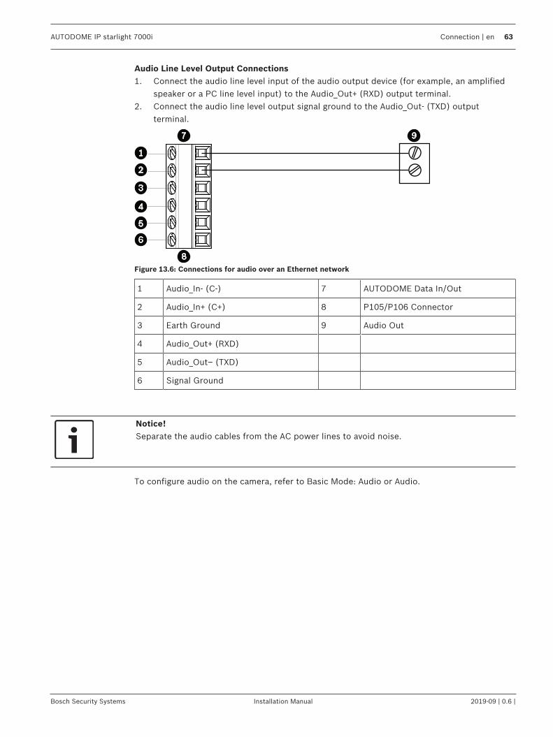
AUTODOME IP starlight 7000i Connection | en 63
Bosch Security Systems Installation Manual 2019-09 | 0.6 |
Audio Line Level Output Connections1. Connect the audio line level input of the audio output device (for example, an amplified
speaker or a PC line level input) to the Audio_Out+ (RXD) output terminal.2. Connect the audio line level output signal ground to the Audio_Out- (TXD) output
terminal.
Figure 13.6: Connections for audio over an Ethernet network
1 Audio_In- (C-) 7 AUTODOME Data In/Out
2 Audio_In+ (C+) 8 P105/P106 Connector
3 Earth Ground 9 Audio Out
4 Audio_Out+ (RXD)
5 Audio_Out– (TXD)
6 Signal Ground
Notice!Separate the audio cables from the AC power lines to avoid noise.
To configure audio on the camera, refer to Basic Mode: Audio or Audio.

64 en | Troubleshooting AUTODOME IP starlight 7000i
2019-09 | 0.6 | Installation Manual Bosch Security Systems
14 Troubleshooting14.1 Rebooting the unit
Reboot the unitAfter a Factory Default or firmware update, reboot the unit if:– You cannot connect to the unit in the Web browser.OR– Configuration Manager or BVMS or similar software identifies the unit as “Videojet
Generic”.4 Reboot the unit using one of the following methods:
– In the web browser, type the IP address and then /reset (without any punctuation). Pressthe Enter key.
OR– In Configuration Manager, right-click the IP address and click Restart.4 Wait two minutes for the process to complete.
If you cannot control the unit after the firmware upgrade, then cycle the power to the unit. If apower reset does not solve the problem, or if Configuration or video management softwareidentifies the unit as “Videojet Generic,” then contact your Bosch Service Center for an RMAfor the unit.

AUTODOME IP starlight 7000i Troubleshooting | en 65
Bosch Security Systems Installation Manual 2019-09 | 0.6 |
14.2 Physical reset buttonEach camera has a hardware reset button. You may need to press the reset button to reset thecamera to factory defaults if you encounter the following circumstances:– You can power up the camera but cannot log on to the camera using the web browser.– The camera doesn’t start up, or fails to power up via PoE.– The camera cannot search an IP address.– The camera’s firmware crashed.– You forgot the password to access the camera.– The image becomes frozen.– You cannot update the firmware.– The camera disconnects from the network at random and needs a reboot.– The camera no longer finds pre-positions (preset positions).– You cannot configure the camera using the web browser.– The camera has no video out.
Notice!A factory default deletes all camera settings including passwords, network settings, andimage settings.Complete the following sequence of steps only if you have no other option to restoreoperation to the camera.
Steps to complete a hardware reset for all camera models1. Apply power to the camera.2. Find the IP address of the camera.3. Log on to the camera using the web browser. (Note: You can use Configuration Manager
to identify the IP address.)4. Find the hardware reset button on the camera. (Refer to the figure below to find the reset
button for your camera model.)5. Push and hold the reset button for more than 8 seconds. The red LED indicator on the
PCBA board will come on to show that the hardware reset started.Note: You can also use a conductive wire to short the terminal block.1. Let the camera complete a self-check. When the self-check completes, the red LED will go
off.2. Find the IP address again.3. Access the camera using the web browser.4. Set the initial service-level password for the camera.

66 en | Troubleshooting AUTODOME IP starlight 7000i
2019-09 | 0.6 | Installation Manual Bosch Security Systems

AUTODOME IP starlight 7000i Troubleshooting | en 67
Bosch Security Systems Installation Manual 2019-09 | 0.6 |
14.3 Customer Service and SupportIf this unit needs service, contact the nearest Bosch Security Systems Service Center forauthorization to return and shipping instructions.USATelephone: 800-366-2283Fax: 800-366-1329Email: [email protected] ServiceTelephone: 888-289-0096Fax: 585-223-9180Email: [email protected] SupportTelephone: 800-326-1450Fax: 717-735-6560Email: [email protected]: 514-738-2434Fax: 514-738-8480Europe, Middle East, Africa, and Asia Pacific RegionsPlease contact your local distributor or Bosch sales office. Use this link:https://www.boschsecurity.com/corporate/where-to-buy/index.html
68 en | Maintenance AUTODOME IP starlight 7000i
2019-09 | 0.6 | Installation Manual Bosch Security Systems
15 Maintenance
All bubbles require special care when handling and cleaning to avoid scratches.
Notice!To avoid excessive moisture saturation inside the housing, limit the amount of time that thebubble is disconnected from the housing. Bosch recommends that the bubble be removedfrom the housing for no more than five (5) minutes.
Bubble HandlingThe bubble may be packaged with a protective plastic sheet. It is recommended that thebubble remain stored this way until it is ready to install. Limit handling the bubble, as anyscratches can quickly affect visibility.
Bubble CleaningIf cleaning the bubble is required, use the following procedures and comply with all thewarnings listed below.
Cleaning the Bubble InteriorThe extremely soft interior surface should not be cleaned by rubbing or dusting with a cloth.Use clean dry compressed air, preferably from a spray can, to remove any dust from theinterior surface.
!
Warning!Do not use alcohol-based solutions to clean the polycarbonate bubble. This will cause thepolycarbonate to cloud and over time cause stress aging, which makes the bubble brittle.
Cleaning the Bubble ExteriorThe exterior of the polycarbonate bubble is hard coated for extra protection. If cleaningbecomes necessary, only use cleaning solutions and cloths suitable for cleaning safety glasslenses. Dry the bubble thoroughly with a dry nonabrasive cloth to prevent water spots. Neverscrub the bubble with any abrasive material or cleaners.Bosch recommends cleaning the exterior of the bubble with NOVUS “No. 1” Plastic Clean &Shine (or equivalent), according to manufacturer’s instructions. Refer towww.novuspolish.com to order or to find a local distributor.
Cautions– Do Not clean bubbles in the hot sun or on very hot days.– Do Not use abrasive or highly alkaline cleaners on the bubble.– Do Not scrape the bubble with razor blades or other sharp instruments.– Do Not use Benzene, Gasoline, Acetone, or Carbon Tetrachloride on the bubble.

AUTODOME IP starlight 7000i Maintenance | 69
Bosch Security Systems Installation Manual 2019-09 | 0.6 |
70 | Maintenance AUTODOME IP starlight 7000i
2019-09 | 0.6 | Installation Manual Bosch Security Systems


Bosch Sicherheitssysteme GmbHRobert-Bosch-Ring 585630 GrasbrunnGermanywww.boschsecurity.com© Bosch Sicherheitssysteme GmbH, 2020
Bosch Security Systems, Inc1706 Hempstead RoadLancaster, PA, 17601USA