Introduction to Autodesk Inventor - VEX Robotics - VEX Robotics
1
Autodesk's VEX® Robotics Curriculum
Unit 16: Bumper and Limit Switch
2 ■ Autodesk's VEX Robotics Unit 16: Bumper and Limit Switch
Overview
In Unit 16: Bumper and Limit Switch, you learn about limit switches, their most common uses inrobotics, and how to integrate them successfully into a complete robot design. You document andcommunicate your decision-making and design process.
The concepts behind bumper and limit switches have countless real-world applications. In STEMConnections, we pose questions regarding a robotic lawnmower. After completing the Think and Buildphases, you see how those concepts come into play in the real world.
Unit Objectives
After completing this unit, you will be able to:
■ Describe the differences between a bumper switch and a limit switch and list some of their uses.■ Use Cable and Harness to add wiring to the bumper switches using Autodesk Inventor
Professional.■ Integrate limit switches into a robot to increase functionality.■ Explain the usefulness of limit switches and their applications, and generate ideas as to where
limit switches can be used to maximize functionality.
Prerequisites
Related resources for Unit 16: Bumper and Limit Switch are:
■ Unit 1: Introduction to VEX and Robotics.■ Unit 2: Introduction to Autodesk Inventor.■ Unit 4: Microcontroller and Transmitter Overview.■ Unit 12: Object Manipulation.■ Unit 15: Linkages.
Key Terms and Definitions
The following key terms are used in Unit 16: Bumper and Limit Switch:
Term
Definition
BumperSwitch
In the VEX system, a type of switch that is inside a plastic casing. It can be exposedto impacts without risking damage to the switch itself. For this reason, it is usefulin any application in which the trigger can be high impact.
Cable A premanufactured grouping of wires that is typically wrapped in some sort ofinsulation or sheath. It is also referred to as a multiconductor cable.
Hard Stop A point at which a mechanical system cannot go any further because it has hit afixed limit.
Overview ■ 3
Term
Definition
Harness A harness assembly contains harness objects such as the wires, cables, ribboncables, and segments that make up a wire harness, and optionally the connectorsto which the wires and cables are attached. Multiple harness assemblies can existwithin an assembly.
Limit Switch In the VEX system, a type of switch with a function similar to that of a bumperswitch. Unlike the bumper switch, the limit switch has a thin sheet-metal arm as itstrigger mechanism, which can be bent into custom shapes for specific applications.
Pins Points added to electrical parts to indicate where to attach wires.
RefDes For reference designator, a simple text string such as J12 or R15 that is used touniquely identify electrical components and component occurrences within thecontext of a harness design. The RefDes maps the part to the schematic wiringdiagram or electrical connectivity data.
Switch A mechanical device used to make or break connections within an electrical circuit.
Wire Existing or custom objects in the Cable & Harness Library. Each wire has a wirename, color style, and outer wire diameter. Other optional properties can also beset, along with any custom properties you need.
Required Supplies and Software
The following supplies and software are used Unit 16: Bumper and Limit Switch:
Supplies
Software
VEX Classroom Lab Kit Autodesk® Inventor® Professional 2010
The robot built in the Unit 16: Bumper andLimit Switch > Build Phase
Notebook and pen
Work surface
Five soda cans
One calculator
One stopwatch
An approximately 6” high stack of textbooks

4 ■ Autodesk's VEX Robotics Unit 16: Bumper and Limit Switch
Supplies
Software
3’ x 3’ of open space
Small container for loose parts
Academic Standards
The following national academic standards are supported in Unit 16: Bumper and Limit Switch:
Phase
Standard
Think Science (NSES)■ Unifying Concepts and Processes: Form and Function■ Physical Science: Motions and Forces■ Science and Technology: Abilities of Technological Design Technology (ITEA)■ 5.8: The Attributes of Design Mathematics (NCTM)■ Algebra Standard: Understand patterns, relations, and functions.■ Measurement Standard: Understand measurable attributes of objects and the
units, systems, and processes of measurement.■ Communication: Communicate mathematical thinking coherently and clearly to
peers, teachers, and others.■ Connections: Recognize and apply mathematics in contexts outside of
mathematics.
Create Science (NSES)■ Unifying Concepts and Processes: Form and Function■ Physical Science: Motions and Forces■ Science and Technology: Abilities of Technological Design Technology (ITEA)■ 5.8: The Attributes of Design■ 5.9: Engineering Design■ 6.12: Use and Maintain Technological Products and Systems Mathematics (NCTM)■ Numbers and Operations: Understand numbers, ways of representing numbers,
relationships among numbers, and number systems.■ Algebra Standard: Understand patterns, relations, and functions.■ Geometry Standard: Use visualization, spatial reasoning, and geometric modeling
to solve problems.■ Measurement Standard: Understand measurable attributes of objects and the
units, systems, and processes of measurement.
Overview ■ 5
Phase
Standard
Build Science (NSES)■ Unifying Concepts and Processes: Form and Function■ Physical Science: Motions and Forces■ Science and Technology: Abilities of Technological Design Technology (ITEA)■ 5.8: The Attributes of Design■ 5.9: Engineering Design■ 6.11: Apply the Design Process Mathematics (NCTM)■ Algebra Standard: Understand patterns, relations, and functions.■ Measurement: Understand measurable attributes of objects and the units,
systems, and processes of measurement.■ Measurement: Apply appropriate techniques, tools, and formulas to determine
measurements.■ Connections: Recognize and apply mathematics in contexts outside of
mathematics.■ Problem Solving: Solve problems that arise in mathematics and in other contexts.■ Problem Solving: Apply and adapt a variety of appropriate strategies to solve
problems.
Amaze Science (NSES)■ Unifying Concepts and Processes: Form and Function■ Physical Science: Motions and Forces■ Science and Technology: Abilities of Technological Design Technology (ITEA)■ 5.8: The Attributes of Design Mathematics (NCTM)■ Algebra Standard: Understand patterns, relations, and functions.■ Communication: Communicate mathematical thinking coherently and clearly to
peers, teachers, and others.■ Connections: Recognize and apply mathematics in contexts outside of
mathematics.■ Measurement: Understand measurable attributes of objects and the units,
systems, and processes of measurement.■ Measurement: Apply appropriate techniques, tools, and formulas to determine
measurements.■ Problem Solving: Solve problems that arise in mathematics and in other contexts.■ Problem Solving: Apply and adapt a variety of appropriate strategies to solve
problems.

6 ■ Autodesk's VEX Robotics Unit 16: Bumper and Limit Switch
Think Phase
Overview
This phase describes characteristics of linkages. It also describes some common applications forlinkages.
Phase Objectives
After completing this phase, you will be able to:
■ Describe a switch. ■ Describe the differences between a bumper switch and a limit switch. ■ List some uses for bumper switches and limit switches.
Prerequisites and Resources
Related phase resources are:
■ Unit 4: Microcontroller and Transmitter Overview.■ Unit 12: Object Manipulation.■ Unit 13: Rotating Joints.
Required Supplies and Software
The following supplies are used in this phase:
Supplies
VEX Classroom Lab Kit
Notebook and pen
Work surface

Think Phase ■ 7
Research and Activity
The focus in this phase is on the VEX Bumper Switch and VEX Limit Switch and two momentaryswitches. A momentary switch is one that sends a signal only when it is triggered. When the trigger isremoved, it springs back to its natural state and there is no signal.
A switch is a mechanical device used to make or break connections within an electrical circuit. Inrobotics, switches can be used by the operator to give the robot commands. Switches can also beplaced on the robot to respond to external triggers.
When a switch is triggered, it completes a circuit which sends a signal to the VEX Microcontroller. Thissignal can be interpreted by the programming in the Microcontroller to trigger some robot action.
Bumper Switch
A bumper switch is inside a plastic casing. As its name suggests, it is designed to act as a bumper. It canbe exposed to impacts without risking damage to the switch itself. For this reason, it is useful in anyapplication in which the trigger can be high impact.
Bumper Switch 1

8 ■ Autodesk's VEX Robotics Unit 16: Bumper and Limit Switch
One common use of a bumper switch is to signal the robot when it has driven into something. Whenthe bumper switch is triggered, it signals the robot to back up.
Two robots that use bumper switches are shown here:

Think Phase ■ 9
Limit Switch
A limit switch has a function similar to that of a bumper switch. Unlike the bumper switch, the limitswitch has a thin sheet-metal arm as its trigger mechanism. This switch is not as durable as thebumper switch. In the event of a high impact, the metal arm will bend or break. However, this is alsothe biggest advantage of the limit switch. The metal arm is designed to be rebent into different shapes.By bending the arm, you can set up the limit switch to fit different applications.
A limit switch is most commonly used to determine when an arm has reached the limit of its travel(hence, the name limit switch). Typically, two limit switches are used, one at each end of the arm'stravel. When the arm is all the way up, it hits the top limit switch, which signals the Microcontrollernot to let the arm rise any farther. When the arm is all the way down, it hits the bottom limit switch,which signals the Microcontroller not to let the arm drop any farther. Some examples of robots usinglimit switches are shown here:

10 ■ Autodesk's VEX Robotics Unit 16: Bumper and Limit Switch
Importance of Limit Switches
Any mechanical system that has a hard stop should have a limit switch. A hard stop is a point at whichthe mechanical system cannot go any farther because it has hit a fixed limit (for example, an armhas jammed against the chassis and cannot go down any farther). If the mechanical system tries tocontinue to move after it has hit a hard stop, it will likely cause damage. A limit switch signals theMicrocontroller that the mechanical system is at the end of its motion and should be prevented frommoving farther. These limit switches keep the system from damaging itself.

Think Phase ■ 11
Preprogrammed Microcontroller
The VEX Microcontroller comes preprogrammed with several options for using bumper switchesand limit switches. Because both these switches have the same functionality, they interface with theMicrocontroller in the same way. Remember, both types of switches do the same thing; they just comein different shapes. Either type of switch can be used for any of these functions.
These switches are used with the VEX Microcontroller by plugging them into the Analog/Digital Ports.
A switch has different effects depending on which port it is plugged into. The table shown describeswhat function each port performs.

12 ■ Autodesk's VEX Robotics Unit 16: Bumper and Limit Switch
Preprogrammed Functions
Three different types of preprogrammed functions are available.
The first type is Autonomous Mode Collision Detection. Note: For this function to work, AutonomousMode must be enabled. To enable Autonomous Mode, a jumper must be installed in Analog/DigitalPort #13. When Autonomous Mode is enabled, a signal on Port 12 results in the robot's backingup and turning left. A signal on Port 11 results in the robot's backing up and turning right. Thisfunctionality is useful for obstacle avoidance.
The second function is Collision Emergency Stop. This functionality applies to Port #9 and Port #10. Ifeither of these ports has a switch plugged into it that is triggered, it will shut down the entire robotfor two seconds. Once the two-second period is over, the robot will come back to life. This is useful forplaying a game of robot tag with bumper switches. Simply mount bumper switches to the back of yourrobot, and if your opponent touches them, your robot will freeze for two seconds.
The third and most useful type of preprogrammed behavior applies to Ports 1 through 8. These portscontrol the limit switch behavior for Motors 4 through 7. Each port controls the direction of a differentmotor. If a switch triggers Port 1, then Motor 4 will not run in the CCW direction. If a switch triggersPort 2, then Motor 4 will not run in the CW direction. These two ports both control Motor 4. So, if youhave an arm being driven by Motor 4, you can put two limit switches on it: one on Port 1 and one onPort 2. The other switches are similarly controlled; refer to the table for more information.
For more information on other preprogrammed functions of the Microcontroller, refer to Unit 4:Microcontroller and Transmitter Overview.

Create Phase ■ 13
Create Phase
Overview
In this phase, you add wiring to bumper and limit switches. Using Cable and Harness, you model acable from the bumper and limit switches to the Microcontroller.
The completed exercise
Phase Objectives
After completing this phase, you will be able to:
■ Use Cable and Harness to add wiring to bumper switches.
Prerequisites and Resources
Before starting this phase, you must have:
■ A working knowledge of the Windows operating system.■ Completed Unit 1: Introduction to Vex and Robotics > Getting Started with Autodesk Inventor.■ Completed Unit 2: Introduction to Autodesk Inventor > QuickStart for Autodesk Inventor.

14 ■ Autodesk's VEX Robotics Unit 16: Bumper and Limit Switch
Technical Overview
The following Autodesk® Inventor® tools are used in this phase. Icon
Name
Description
Place Pin Used to establish the location and names of individual pins on AutodeskInventor parts. To define the pins, you select the Place Pin tool, pick apoint in the graphics window, and then add a pin name and optionalproperties.
Plane A construction feature that defines the parametric location of a sketchplane in 3D space. A work plane is useful when no planar face exists touse as a sketch plane, for example, when sketching on curved or toroidalfaces. A work plane can be incorporated into dimension and constraintschemes.
Create 2DSketch
A sketch consists of the sketch plane, a coordinate system, 2D curves, andthe dimensions and constraints applied to the curves. A sketch may alsoincorporate construction geometry or reference geometry. Sketches areused to define feature profiles and paths.
ProjectGeometry
Projects geometry (model edges, vertices, work axes, work points,or other sketch geometry) onto the active sketch plane as referencegeometry.
Return Used to quit in-place editing and quickly return to the desiredenvironment. The destination depends on which modeling environmentyou are working in.
Work Point Work points can be placed or projected onto part faces, linear edges,or onto an arc or a circle. Work points can be constrained to the centerpoints of arcs, circles, and ellipses. In Cable and Harness, they are added to Autodesk Inventor parts to assistin the placement of a segment.
CreateHarness
Adds the harness subassembly to an assembly file with the specified nameand location and activates the Cable and Harness panel bar. The harnesssubassembly contains the origin information, a single harness part, andall the cable and harness specific data. The harness part file is createdand saved to the location of the parent harness assembly. It has the samename as the harness assembly, with an .ipt extension.

Create Phase ■ 15
Icon
Name
Description
Create Wire Used to create a wire between two pins within a harness assembly. Thepins can exist on electrical components (connectors) or splices. The wirethat is created is selected from the Cable & Harness Library.
CreateSegment
Harness segments represent the possible paths that wires and cable wiresmay take through the harness assembly. The segments represent a virtualbundle of wires and cables. Each mouse click in the graphics windowcreates a work point on the segment. Work points are used to manipulatethe segment into its desired position and shape.
AutomaticRoute
Used to route one or more selected unrouted wires or cables or allunrouted wires or cables into segments in the active harness assembly.Routed wires (including cable wires) are ignored.
Required Supplies and Software
The following software is used in this phase:
Software
Autodesk Inventor Professional 2010
16 ■ Autodesk's VEX Robotics Unit 16: Bumper and Limit Switch
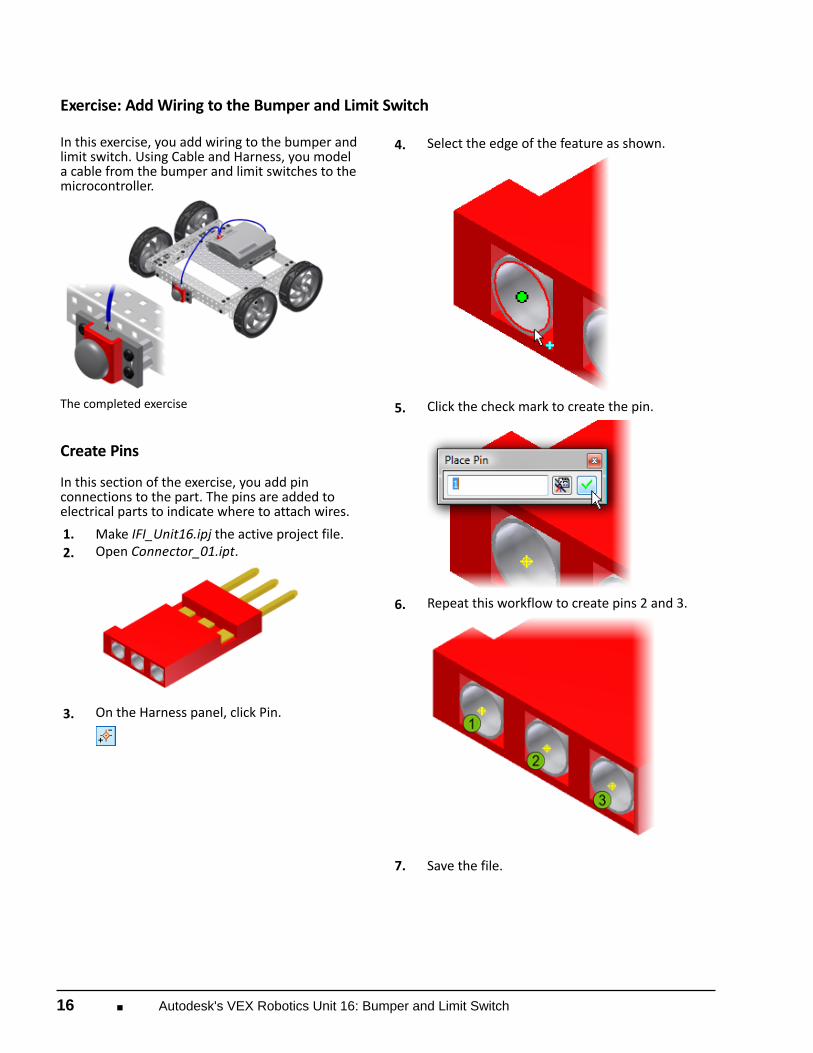
Exercise: Add Wiring to the Bumper and Limit Switch In this exercise, you add wiring to the bumper andlimit switch. Using Cable and Harness, you modela cable from the bumper and limit switches to themicrocontroller.
The completed exercise
Create Pins In this section of the exercise, you add pinconnections to the part. The pins are added toelectrical parts to indicate where to attach wires. 1. Make IFI_Unit16.ipj the active project file. 2.
Open Connector_01.ipt.
3.
On the Harness panel, click Pin.
4.
Select the edge of the feature as shown.
5.
Click the check mark to create the pin.
6.
Repeat this workflow to create pins 2 and 3.
7. Save the file.

Create Phase ■ 17
Add Work Points In this section of the exercise, you create two workpoints. You use the points to ensure that the wireharness is at a right angle to the face of the connector. 1.
On the Work Features panel, click Plane.
2.
Select the end face of the connector and dragaway from the connector. In the Offset box,enter 0.25.
3.
Click the check mark to create the work plane.
4.
Repeat this workflow to create a work plane 0.5away from the face of the connector.
5.
On the Sketch panel, click Create 2D Sketch.
6. Select the first work plane.
7.
On the Draw panel, click Project Geometry.
8.
Click the middle pin (2). The pin is projectedonto the sketch.
9.
On the Quick Access toolbar, click Return.
10.
On the Work Features panel, click Work Point.
11. Select the projected point. 12. Repeat this workflow for the second work
plane. You should now have two work points. 13.
Turn off the visibility of the sketches and workplanes.
14. Save the file. 15. Close the file.

18 ■ Autodesk's VEX Robotics Unit 16: Bumper and Limit Switch
Add the Wires In this section of the exercise, you add thewires between the bumper limit switch and theMicrocontroller. 1.
Open Wiring_Assembly.iam.
2.
On the Begin panel, click Cable and Harness.
3.
Click OK. A new harness subassembly is createdand listed in the browser.
4.
On the Create panel, click Create Wire.
5.
In the Create Wire dialog box, select Alphafrom the Category list. Select 3047-BLK fromthe Name list.
6.
Zoom into the top of the bumper switch.
7.
Click the pin on the left. It is named Pin 3.
8.
Zoom and pan to the Microcontroller. On theconnector on the left, click the pin on the left.It is also named Pin 3. Click Apply.
9. In the Create Wire dialog box, select 3047-RED
from the Name list. 10. Select the pin in the middle. It is named Pin 2. 11. Zoom and pan to the bumper switch. Select the
pin in the middle. It is named Pin 2. Click Apply. 12. In the Create Wire dialog box, select 3047-WHT
from the Name list. 13. Select the pin on the right. It is named Pin 1.

Create Phase ■ 19
14.
Zoom and pan to the Microcontroller. Selectthe pin on the right. It is also named Pin 1. ClickApply. The wires are attached to each pin.
15. Click Cancel.
Create a Segment In this section of the exercise, you create a segmentfor the wires. 1.
Zoom into the bumper switch.
2.
On the Create panel, click Create Segment.
3.
Select the work point (1) closest to the switch.
4.
Select the next work point (2).
5. Zoom and pan to the connector. 6.
Select the work point (3) above the connector.
20 ■ Autodesk's VEX Robotics Unit 16: Bumper and Limit Switch
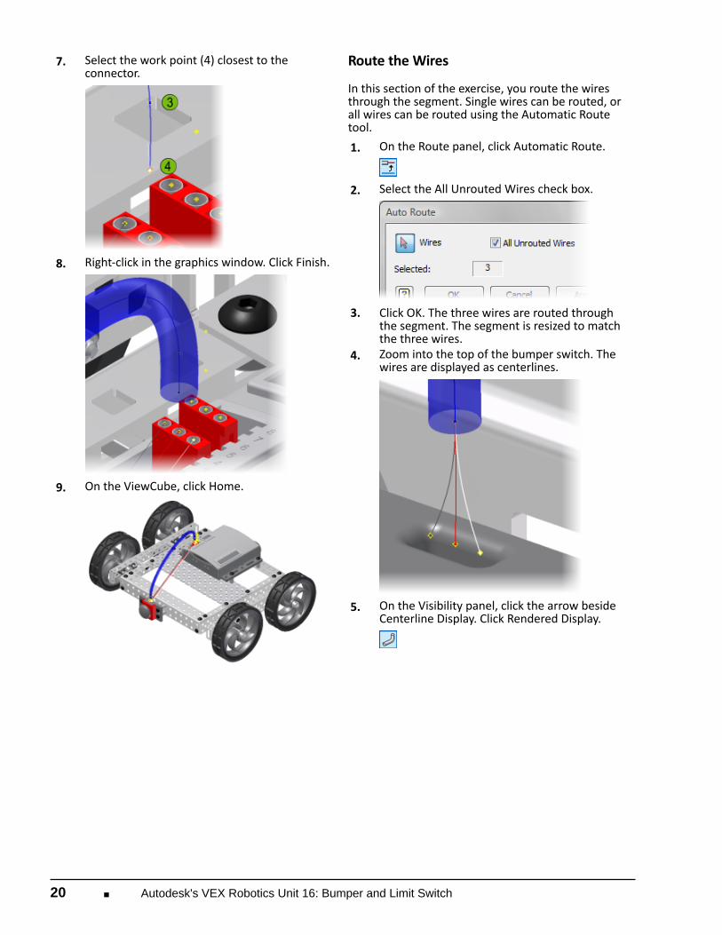
7.
Select the work point (4) closest to theconnector.
8.
Right-click in the graphics window. Click Finish.
9.
On the ViewCube, click Home.
Route the Wires In this section of the exercise, you route the wiresthrough the segment. Single wires can be routed, orall wires can be routed using the Automatic Routetool. 1.
On the Route panel, click Automatic Route.
2.
Select the All Unrouted Wires check box.
3. Click OK. The three wires are routed through
the segment. The segment is resized to matchthe three wires.
4.
Zoom into the top of the bumper switch. Thewires are displayed as centerlines.
5.
On the Visibility panel, click the arrow besideCenterline Display. Click Rendered Display.

Create Phase ■ 21
6.
On the Quick Access toolbar, click Return.
Add a Second Segment In this section of the exercise, you add a secondsegment. 1.
On the Begin panel, click Cable and Harness.
2. Click OK. A second harness subassembly is
created and listed in the browser. 3. On the ViewCube, click the top right corner. 4.
Using the workflow from the previous sections,add a second segment between the bumperswitch and the connector.
5.
On the Quick Access toolbar, click Return.
6. On the ViewCube, click Home. 7. Click Save. 8. Close the file.

22 ■ Autodesk's VEX Robotics Unit 16: Bumper and Limit Switch
Build Phase
Overview
In this phase, you add limit switches to the robot from Unit 15: Linkages, to restrict the motion of yourlinkage.
Phase Objectives
After completing this phase, you will be able to:
■ Integrate limit switches into a robot to increase functionality.
Prerequisites and Resources
Before starting this phase, you must have:
■ Completed Unit 16: Bumper and Limit Switch > Think Phase.
Related phase resources are:
■ Unit 1: Introduction to VEX and Robotics.■ Unit 4: Microcontroller and Transmitter Overview.■ Unit 12: Object Manipulation.■ Unit 13: Rotating Joints.■ Unit 15: Linkages.

Build Phase ■ 23
Required Supplies and Software
The following supplies are used in this phase:
Supplies
VEX Classroom Lab Kit
The robot built in the Unit 15: Linkages > Build Phase
Notebook and pen
Work surface
Small storage container for loose parts
An approximately 6” high stack of textbooks
Measuring tape
Optional: Autodesk Inventor Professional 2010
Activity
Add Limit Switches
In this activity, you add limit switches to your robot to restrict the motion of your linkage. Thechallenge in the Amaze Phase will be to place five sodacans on a stack of textbooks as quickly aspossible. Properly placed limit switchesenable you to perform this task much faster.
1. Measure the exact height of your stack of textbooks. 2. Review the Think Phase of Unit 16 and the Sensors section of the Inventor’s Guide for VEX limit
switch behavior.

24 ■ Autodesk's VEX Robotics Unit 16: Bumper and Limit Switch
3.
In your notebook, brainstorm locations and implementations of where you will place your limitswitches. An example of a limit switch mounted to an arm is shown in the following image.
When deciding where to place your limit switches, you need to consider many factors, some ofwhich include:
■ What range of motion needs to be limited?■ Where does the arm need to be stopped?■ How many limit switches are needed?■ What space is there to mount the switch?■ Will special mounting points need to be added?■ How can the switch be mounted to avoid running directly into it?
Work as professionals in the engineering and design fields by leveraging the powerof Autodesk Inventor to explore potential solutions through the creation and testing of digitalprototypes. Note: Come to class prepared to build and test your best ideas! Team members can download afree version of Autodesk Inventor Professional to use at home by joining the Autodesk StudentEngineering and Design Community today at www.autodesk.com/edcommunity.
4. Based on your criteria, choose a design and start building! 5. Once your limit switches are mounted, hook them up to a Microcontroller and test that they
function as planned. Make modifications as needed. 6. Move on to the Amaze Phase and get ready for your upcoming challenge!
Amaze Phase ■ 25
Amaze Phase
Overview
In this phase, you test the new functionality of your robot by attempting to place five soda cans on aplatform as quickly as possible.
Phase Objectives
After completing this phase, you will be able to:
■ Explain the usefulness of limit switches and their applications. ■ Generate ideas as to where limit switches can be used to maximize functionality.
Prerequisites and Resources
Before starting this phase, you must have:
■ Completed the Unit 16: Bumper and Limit Switch > Think Phase. ■ Completed the Unit 16: Bumper and Limit Switch > Build Phase. ■ An assembled robot from Unit 15: Linkages that consists of a linkage from Unit 14: Accumulator
Design > Build Phase attached to the gripper from Unit 12: Object Manipulation > Build Phase thatis attached to a drivetrain of your choice.
Related phase resources are:
■ Unit 1: Introduction to VEX and Robotics.■ Unit 4: Microcontroller and Transmitter Overview.■ Unit 12: Object Manipulation.■ Unit 13: Rotating Joints.■ Unit 15: Linkages.

26 ■ Autodesk's VEX Robotics Unit 16: Bumper and Limit Switch
Required Supplies and Software
The following supplies are used in this phase:
Supplies
VEX Classroom Lab Kit
The robot built in the Unit 16: Bumper and LImit Switch > Build Phase
Notebook and pen
Work surface
Five soda cans
One calculator
One stopwatch
An approximately 6” high stack of textbooks
3’ x 3’ of open space
Evaluation
Soda Can Platform Challenge
In this challenge, you test the new functionality of your robot by attempting to place five soda cans ona platform as quickly as possible.
1. Place the stack of textbooks on the ground. 2. Place your robot behind the textbooks.

Amaze Phase ■ 27
3.
Place a column of five soda cans behind your robot. See Figure 1.
4. To begin this challenge, you can compare the performance with and without limit switches.
Unplug your limit switches. 5. Using your robot, place the five cans on top of the stack of textbooks as quickly as possible. Start
timing once the first can is grabbed, and stop timing when the last can is placed on the stack.Record this time in your engineering notebook.
6. Repeat this task five times, recording your time for each trial. 7. Plug your limit switches back in. 8. Repeat the same task as earlier, except now use the functionality of the limit switches. Perform
the task five times, recording your time for each trial.
Engineering Notebook
Calculate the average time to complete the task with and without limit switches.■ Which time was faster? Why do you think this is?■ Limit switches are used in many different applications. Think back to all the robots you have built in
the past units. How can you improve them with limit switches?■ List some real-world applications of limit switches.
Presentation
Present your design to the class. Explain how you were able to integrate the switches into yourdesign and the effects they had on your robot. Talk about the criteria you used to decide on yourimplementation.

28 ■ Autodesk's VEX Robotics Unit 16: Bumper and Limit Switch
STEM Connections
Background
You are given the opportunity to develop a robot that safely takes care of mowing any size lawn.A critical aspect of the design is to maximize maneuverability and to ensure that the mower neverendangers anyone and cannot cause property damage or inflict damage in itself.
Science1. Bumper and limit switches act by turning on or off electrical current. Knowing this, what materials
would be used at the connection points where current is turned on or off?2. When elecrical conductivity is involved, why is the selection of materials important? What
provisions do you need to make in order to prevent the electrical current from being accidentallyswitched on or off?
3. The outer casing of a bumper switch is made out of plastic; the bumper pad is made from anelastomer or rubber. Why are these materials used for this application?
4. Because a lawnmower is used outdoors, what are some of the characteristics you want in thematerials that are used for the bumper switch housing?
1. As the robotic mower does its job, you want to make sure that it corrects its movement if it runsinto something. How can you use bumper switches to accomplish this? Where do you mount theswitches?
2. In order to turn the mower 90 degrees, you incorporate a skid steering system (wheels on oneside turn forward; wheels on the opposing side turn in the opposite direction). How can you usebumper switches to control this action?
3. Similarly, after completing a row, you want the mower to move over and continue cutting in theopposite direction. How can you use bumper switches to control this action?

STEM Connections ■ 29
Engineering
One of the biggest safety hazards associated with a lawn mower involves hand injury from a blade thatstarts spinning when a person tries to clean out the undercarriage of the mower.
1. How can you use limit switches to absolutely prevent this type of injury? How can you make sure
that the limit switches always return to their original operating position in order to maintainabsolute safety?
2. How do you prevent the effects of the environment (water, mud, accumulated grass) fromimpacting the performance of the limit switches?
Math
The robotic lawn mower moves at a speed of two feet per second. As it moves forward, the diameterof the blade enables the machine to cut a section of grass that is 18 inches wide. The mower is goingto be used on a rectangular area of lawn measuring 110 feet long x 45 feet deep. The mower starts outin one corner and runs the full horizontal length of 110 feet. When the mower reaches the end of onerow, a bumper switch comes in contact with a border that runs the entire depth of the lawn (45 feet)on both ends. Upon contact, it takes six seconds for the mower to maneuver into position for mowingback in the opposite direction. When it starts mowing in the reverse direction, the mower overlapsthe first cut section by four inches and then cuts another section that is 14 inches wide. It repeats thispattern until the whole lawn is mowed.
Based upon this information and assuming no obstructions exist, how long will it take for the roboticmower to cut the entire lawn? If you have two identical robotic mowers and you start each of themin opposite corners at the exact same time, how long will it take for them to meet if one mower is setto mow at a speed of two feet per second and the other mows at a rate of three feet per second. Atthese rates, where inside the 110-foot x 45-foot rectangle will the two mowers meet (noted as x and ycoordinates) to the nearest feet?

30 ■ Autodesk's VEX Robotics Unit 16: Bumper and Limit Switch