AutoCAD LT 2014 Preview Guide - autodesk.blogs.com · AutoCAD LT 2014 Preview Guide ... same...
21
1 AutoCAD LT 2014 Preview Guide Capture your 2D concepts with the connected design tools of Autodesk® AutoCAD LT® drafting software. Use powerful documentation tools to produce more precise technical drawings that you can efficiently edit, repurpose, and share with confidence. Help ensure accurate dimensions and technical details that faithfully convey the specifics of your design. With the genuine DWG™ technology in AutoCAD LT, you can produce drawing files that are compatible with other AutoCAD®‐based software and utilize sharing options for smoother workflow integration with project stakeholders and colleagues. With a focus on drafting productivity, AutoCAD LT is built for effective design documentation.
Transcript of AutoCAD LT 2014 Preview Guide - autodesk.blogs.com · AutoCAD LT 2014 Preview Guide ... same...
1
AutoCADLT2014PreviewGuide
Capture your 2D concepts with the connected design tools of Autodesk® AutoCAD LT® drafting software.
Use powerful documentation tools to produce more precise technical drawings that you can efficiently
edit, repurpose, and share with confidence. Help ensure accurate dimensions and technical details that
faithfully convey the specifics of your design. With the genuine DWG™ technology in AutoCAD LT, you
can produce drawing files that are compatible with other AutoCAD®‐based software and utilize sharing
options for smoother workflow integration with project stakeholders and colleagues. With a focus on
drafting productivity, AutoCAD LT is built for effective design documentation.
2
TableofContents
User Interaction ............................................................................................................................................ 4
Help system ............................................................................................................................................... 4
Command line ........................................................................................................................................... 5
File tabs ..................................................................................................................................................... 8
Layer management ................................................................................................................................. 10
Xref enhancements ................................................................................................................................. 11
Documentation ........................................................................................................................................... 12
Geographic location ................................................................................................................................ 12
Drawing enhancements .......................................................................................................................... 18
Annotation enhancements ..................................................................................................................... 18
Connection .................................................................................................................................................. 19
Design Feed ............................................................................................................................................. 19
Customization ............................................................................................................................................. 21
Operating systems .................................................................................................................................. 21
3
Introduction
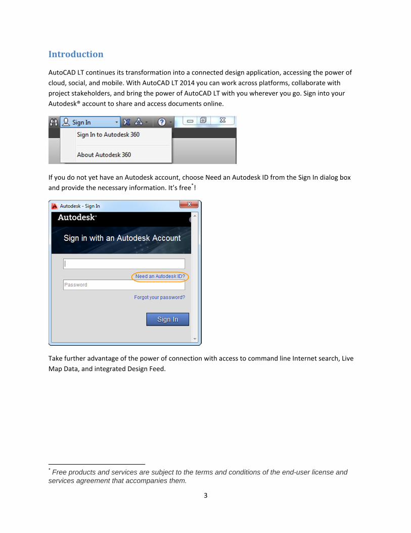
AutoCAD LT continues its transformation into a connected design application, accessing the power of
cloud, social, and mobile. With AutoCAD LT 2014 you can work across platforms, collaborate with
project stakeholders, and bring the power of AutoCAD LT with you wherever you go. Sign into your
Autodesk® account to share and access documents online.
If you do not yet have an Autodesk account, choose Need an Autodesk ID from the Sign In dialog box
and provide the necessary information. It’s free*!
Take further advantage of the power of connection with access to command line Internet search, Live
Map Data, and integrated Design Feed.
* Free products and services are subject to the terms and conditions of the end-user license and services agreement that accompanies them.
4
UserInteraction
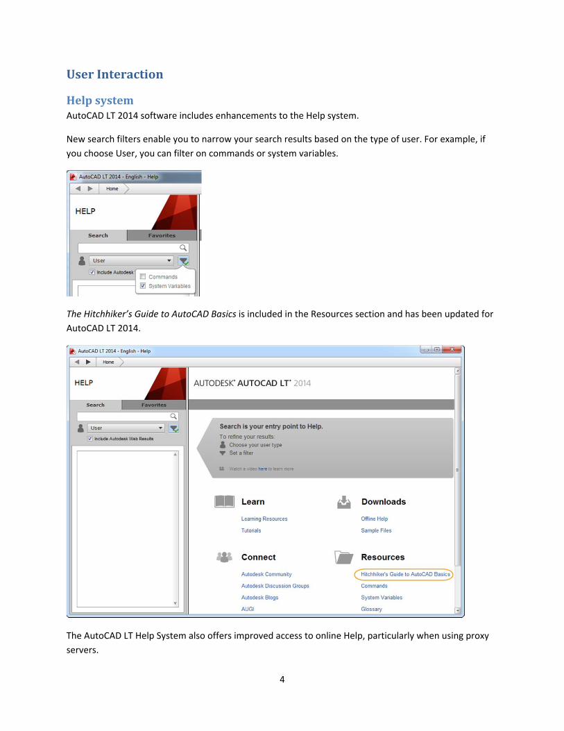
HelpsystemAutoCAD LT 2014 software includes enhancements to the Help system.
New search filters enable you to narrow your search results based on the type of user. For example, if
you choose User, you can filter on commands or system variables.
The Hitchhiker’s Guide to AutoCAD Basics is included in the Resources section and has been updated for
AutoCAD LT 2014.
The AutoCAD LT Help System also offers improved access to online Help, particularly when using proxy
servers.
5
CommandlineThe Command Line interface is enhanced in AutoCAD LT 2014 to provide smarter, more efficient access
to commands and system variables. And you can use the command line to find other content, such as
hatch patterns and Internet help.
AutoCorrectThe command line in AutoCAD LT 2014 supports AutoCorrect. If you mistype a command, instead
responding with “Unknown command,” AutoCAD autocorrects to the most relevant and valid AutoCAD
command. For example, if you accidentally type TABEL, the TABLE command is automatically launched.
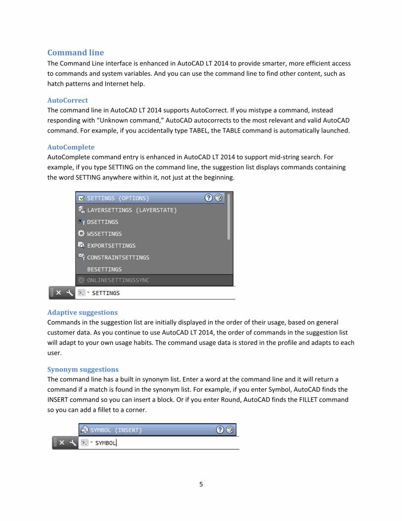
AutoCompleteAutoComplete command entry is enhanced in AutoCAD LT 2014 to support mid‐string search. For
example, if you type SETTING on the command line, the suggestion list displays commands containing
the word SETTING anywhere within it, not just at the beginning.
AdaptivesuggestionsCommands in the suggestion list are initially displayed in the order of their usage, based on general
customer data. As you continue to use AutoCAD LT 2014, the order of commands in the suggestion list
will adapt to your own usage habits. The command usage data is stored in the profile and adapts to each
user.
SynonymsuggestionsThe command line has a built in synonym list. Enter a word at the command line and it will return a
command if a match is found in the synonym list. For example, if you enter Symbol, AutoCAD finds the
INSERT command so you can insert a block. Or if you enter Round, AutoCAD finds the FILLET command
so you can add a fillet to a corner.
6
You can add your own words to the AutoCorrect and Synonym lists using the Edit Aliases tool from the
Manage ribbon tab.
InternetsearchIn AutoCAD LT 2014, you can quickly search for more information on a command or system variable in
the suggestion list. Move the cursor over the command or system variable in the list and choose the
Help or Internet icons to search for relevant information. The term AutoCAD is automatically prepended
to the current term for searching the Internet.
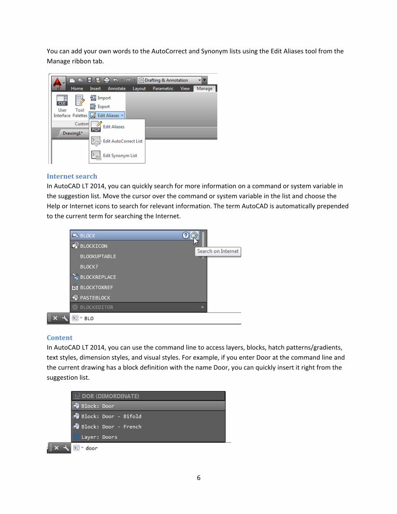
ContentIn AutoCAD LT 2014, you can use the command line to access layers, blocks, hatch patterns/gradients,
text styles, dimension styles, and visual styles. For example, if you enter Door at the command line and
the current drawing has a block definition with the name Door, you can quickly insert it right from the
suggestion list.
7
CategoriesTo make the suggestion list easier to navigate, system variables and other content are organized into
expandable categories. You can expand a category to see the results or press the Tab key to cycle
through each category.
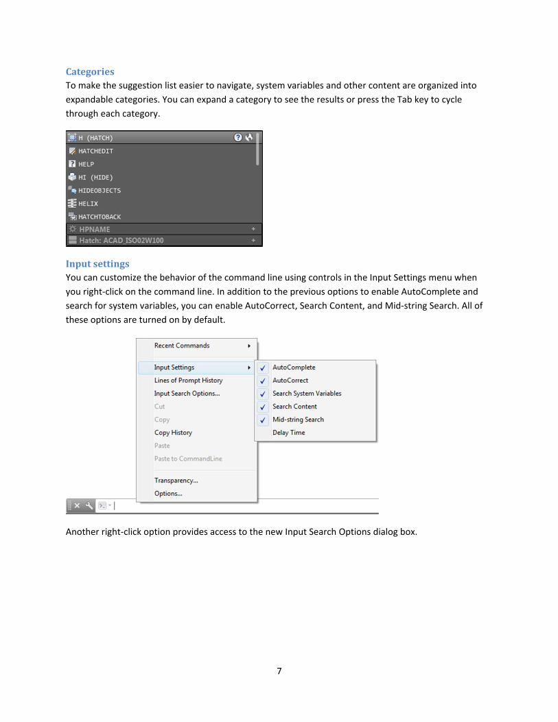
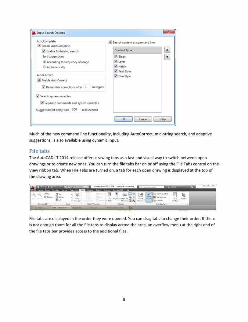
InputsettingsYou can customize the behavior of the command line using controls in the Input Settings menu when
you right‐click on the command line. In addition to the previous options to enable AutoComplete and
search for system variables, you can enable AutoCorrect, Search Content, and Mid‐string Search. All of
these options are turned on by default.
Another right‐click option provides access to the new Input Search Options dialog box.
8
Much of the new command line functionality, including AutoCorrect, mid‐string search, and adaptive
suggestions, is also available using dynamic input.
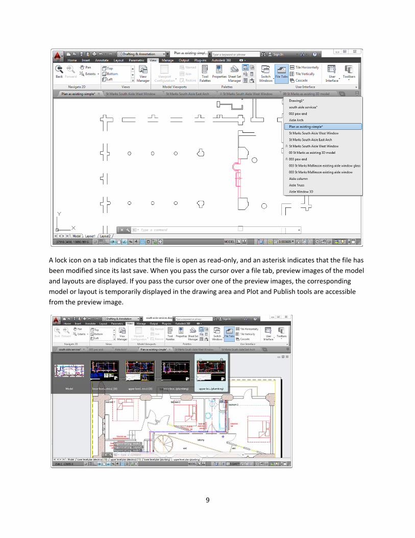
FiletabsThe AutoCAD LT 2014 release offers drawing tabs as a fast and visual way to switch between open
drawings or to create new ones. You can turn the file tabs bar on or off using the File Tabs control on the
View ribbon tab. When File Tabs are turned on, a tab for each open drawing is displayed at the top of
the drawing area.
File tabs are displayed in the order they were opened. You can drag tabs to change their order. If there
is not enough room for all the file tabs to display across the area, an overflow menu at the right end of
the file tabs bar provides access to the additional files.
9
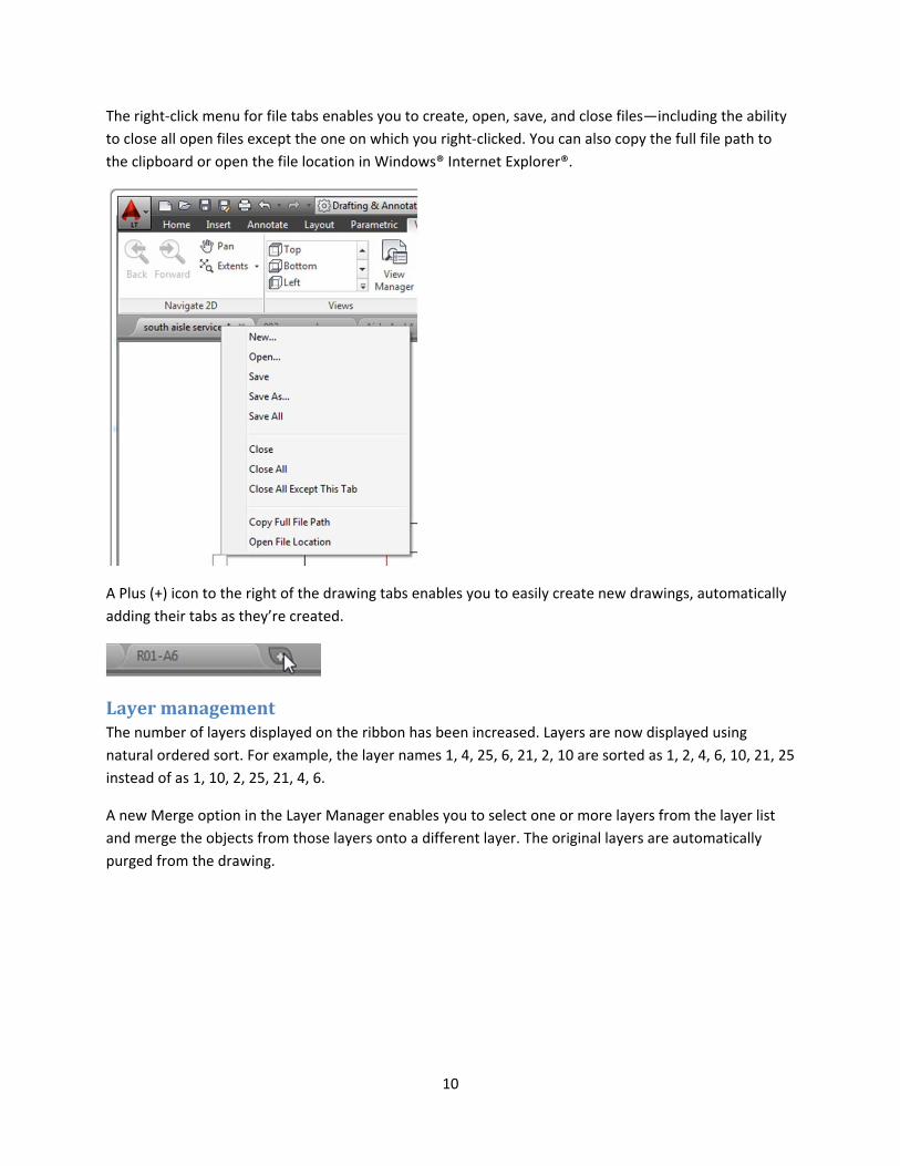
A lock icon on a tab indicates that the file is open as read‐only, and an asterisk indicates that the file has
been modified since its last save. When you pass the cursor over a file tab, preview images of the model
and layouts are displayed. If you pass the cursor over one of the preview images, the corresponding
model or layout is temporarily displayed in the drawing area and Plot and Publish tools are accessible
from the preview image.
10
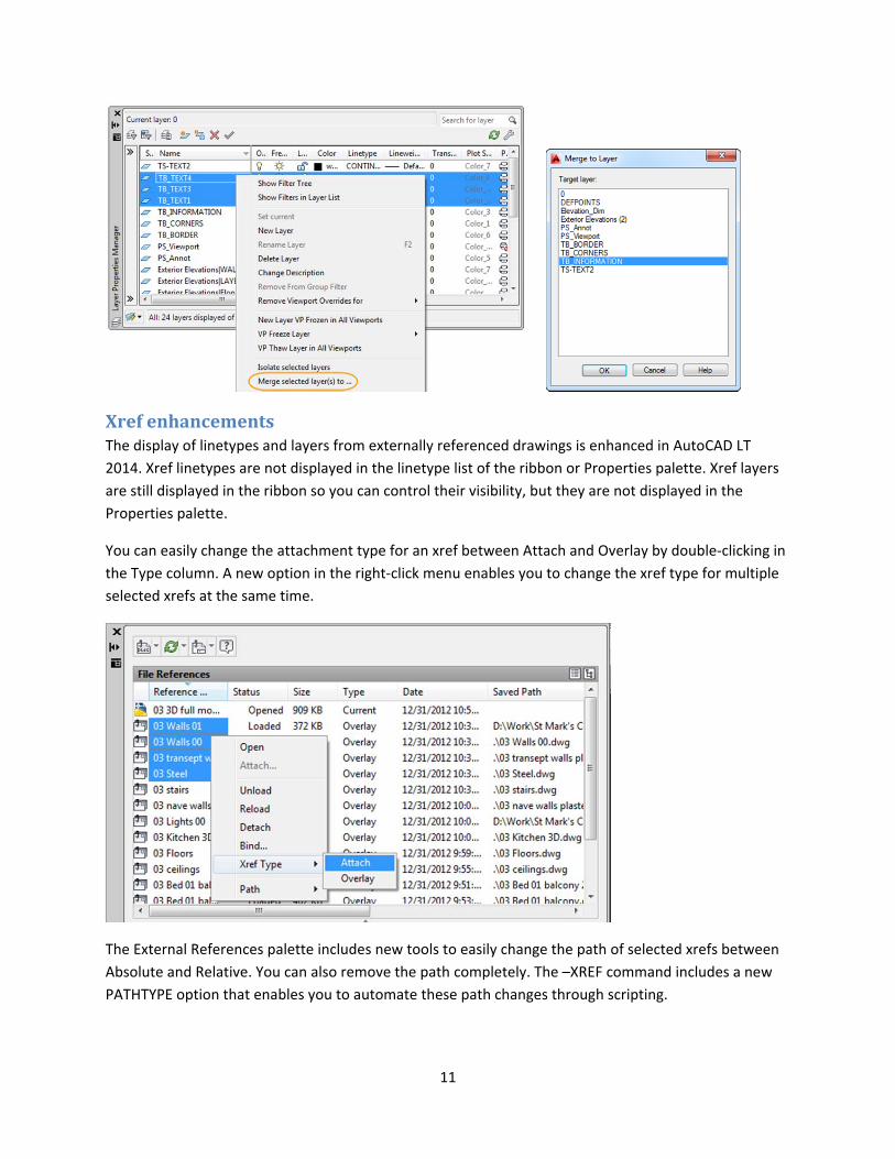
The right‐click menu for file tabs enables you to create, open, save, and close files—including the ability
to close all open files except the one on which you right‐clicked. You can also copy the full file path to
the clipboard or open the file location in Windows® Internet Explorer®.
A Plus (+) icon to the right of the drawing tabs enables you to easily create new drawings, automatically
adding their tabs as they’re created.
LayermanagementThe number of layers displayed on the ribbon has been increased. Layers are now displayed using
natural ordered sort. For example, the layer names 1, 4, 25, 6, 21, 2, 10 are sorted as 1, 2, 4, 6, 10, 21, 25
instead of as 1, 10, 2, 25, 21, 4, 6.
A new Merge option in the Layer Manager enables you to select one or more layers from the layer list
and merge the objects from those layers onto a different layer. The original layers are automatically
purged from the drawing.
11
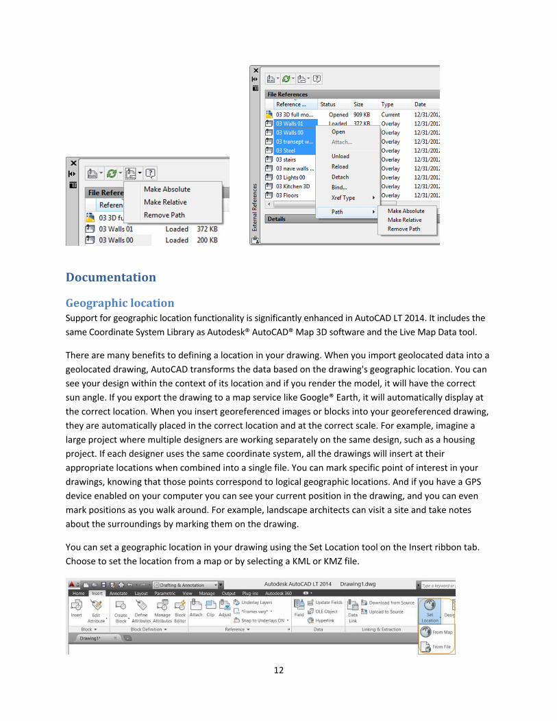
XrefenhancementsThe display of linetypes and layers from externally referenced drawings is enhanced in AutoCAD LT
2014. Xref linetypes are not displayed in the linetype list of the ribbon or Properties palette. Xref layers
are still displayed in the ribbon so you can control their visibility, but they are not displayed in the
Properties palette.
You can easily change the attachment type for an xref between Attach and Overlay by double‐clicking in
the Type column. A new option in the right‐click menu enables you to change the xref type for multiple
selected xrefs at the same time.
The External References palette includes new tools to easily change the path of selected xrefs between
Absolute and Relative. You can also remove the path completely. The –XREF command includes a new
PATHTYPE option that enables you to automate these path changes through scripting.
12
Documentation
GeographiclocationSupport for geographic location functionality is significantly enhanced in AutoCAD LT 2014. It includes the
same Coordinate System Library as Autodesk® AutoCAD® Map 3D software and the Live Map Data tool.
There are many benefits to defining a location in your drawing. When you import geolocated data into a
geolocated drawing, AutoCAD transforms the data based on the drawing's geographic location. You can
see your design within the context of its location and if you render the model, it will have the correct
sun angle. If you export the drawing to a map service like Google® Earth, it will automatically display at
the correct location. When you insert georeferenced images or blocks into your georeferenced drawing,
they are automatically placed in the correct location and at the correct scale. For example, imagine a
large project where multiple designers are working separately on the same design, such as a housing
project. If each designer uses the same coordinate system, all the drawings will insert at their
appropriate locations when combined into a single file. You can mark specific point of interest in your
drawings, knowing that those points correspond to logical geographic locations. And if you have a GPS
device enabled on your computer you can see your current position in the drawing, and you can even
mark positions as you walk around. For example, landscape architects can visit a site and take notes
about the surroundings by marking them on the drawing.
You can set a geographic location in your drawing using the Set Location tool on the Insert ribbon tab.
Choose to set the location from a map or by selecting a KML or KMZ file.
13
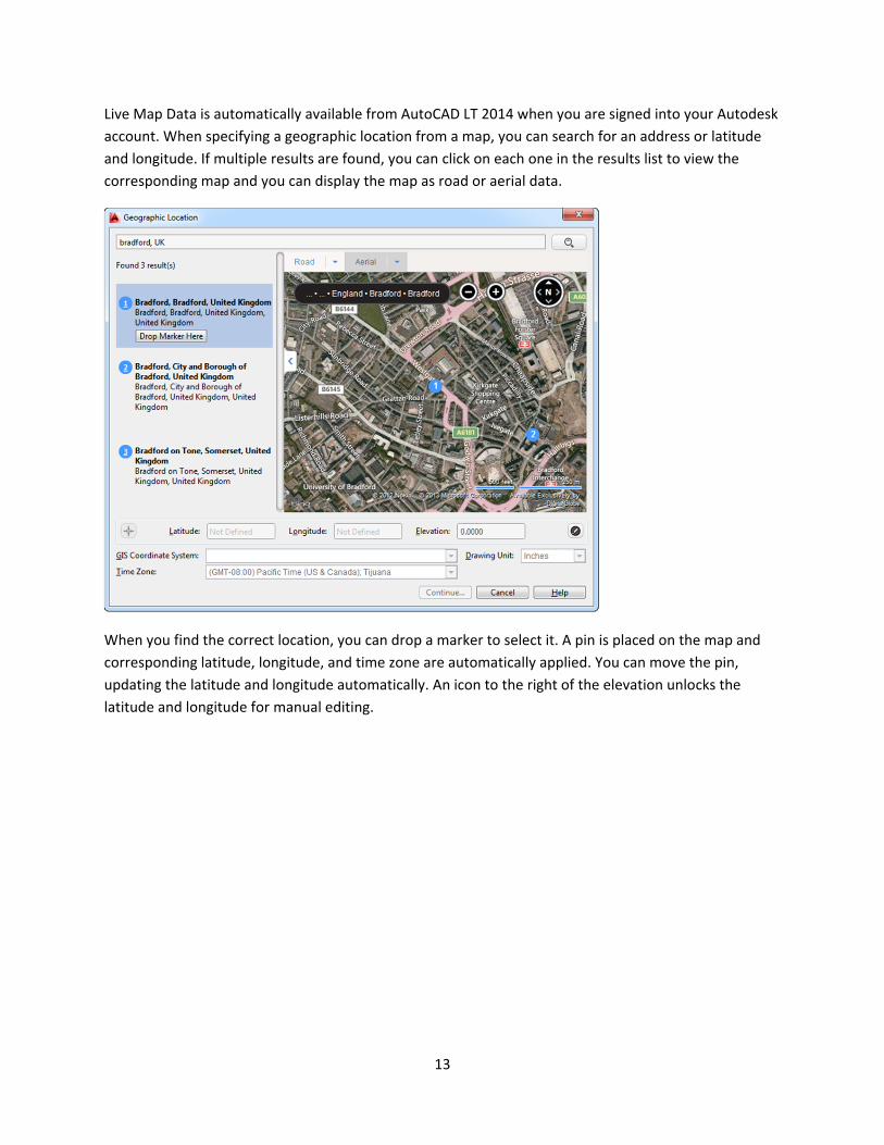
Live Map Data is automatically available from AutoCAD LT 2014 when you are signed into your Autodesk
account. When specifying a geographic location from a map, you can search for an address or latitude
and longitude. If multiple results are found, you can click on each one in the results list to view the
corresponding map and you can display the map as road or aerial data.
When you find the correct location, you can drop a marker to select it. A pin is placed on the map and
corresponding latitude, longitude, and time zone are automatically applied. You can move the pin,
updating the latitude and longitude automatically. An icon to the right of the elevation unlocks the
latitude and longitude for manual editing.
14
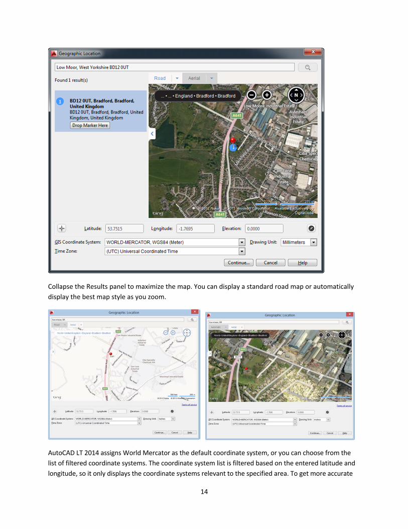
Collapse the Results panel to maximize the map. You can display a standard road map or automatically
display the best map style as you zoom.
AutoCAD LT 2014 assigns World Mercator as the default coordinate system, or you can choose from the
list of filtered coordinate systems. The coordinate system list is filtered based on the entered latitude and
longitude, so it only displays the coordinate systems relevant to the specified area. To get more accurate
15
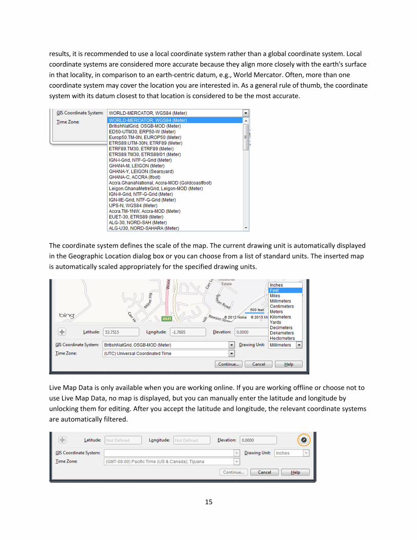
results, it is recommended to use a local coordinate system rather than a global coordinate system. Local
coordinate systems are considered more accurate because they align more closely with the earth's surface
in that locality, in comparison to an earth‐centric datum, e.g., World Mercator. Often, more than one
coordinate system may cover the location you are interested in. As a general rule of thumb, the coordinate
system with its datum closest to that location is considered to be the most accurate.
The coordinate system defines the scale of the map. The current drawing unit is automatically displayed
in the Geographic Location dialog box or you can choose from a list of standard units. The inserted map
is automatically scaled appropriately for the specified drawing units.
Live Map Data is only available when you are working online. If you are working offline or choose not to
use Live Map Data, no map is displayed, but you can manually enter the latitude and longitude by
unlocking them for editing. After you accept the latitude and longitude, the relevant coordinate systems
are automatically filtered.
16
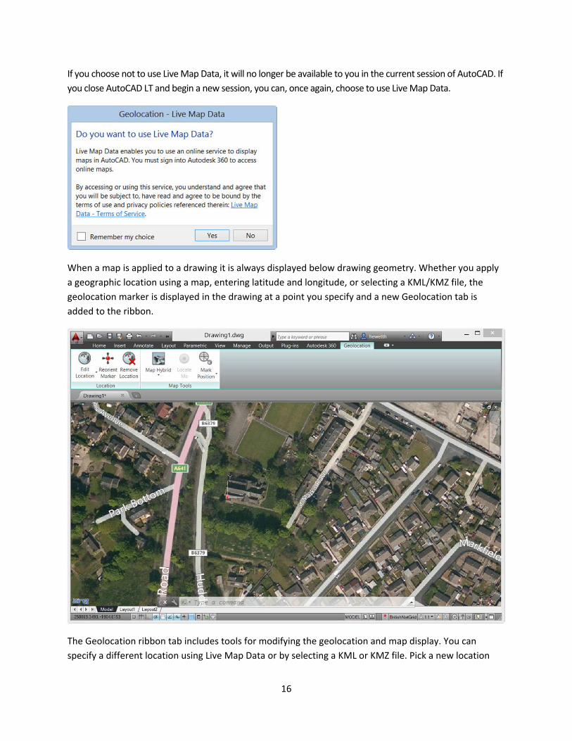
If you choose not to use Live Map Data, it will no longer be available to you in the current session of AutoCAD. If
you close AutoCAD LT and begin a new session, you can, once again, choose to use Live Map Data.
When a map is applied to a drawing it is always displayed below drawing geometry. Whether you apply
a geographic location using a map, entering latitude and longitude, or selecting a KML/KMZ file, the
geolocation marker is displayed in the drawing at a point you specify and a new Geolocation tab is
added to the ribbon.
The Geolocation ribbon tab includes tools for modifying the geolocation and map display. You can
specify a different location using Live Map Data or by selecting a KML or KMZ file. Pick a new location
17
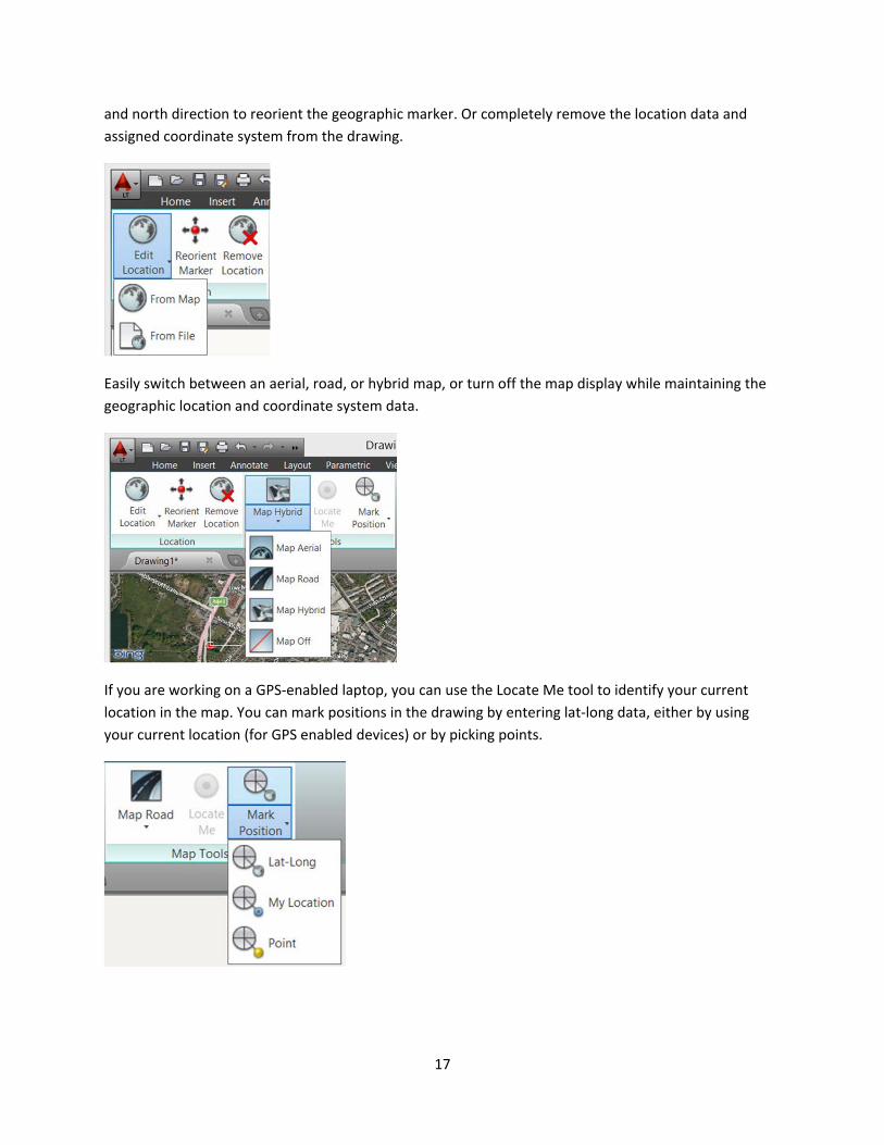
and north direction to reorient the geographic marker. Or completely remove the location data and
assigned coordinate system from the drawing.
Easily switch between an aerial, road, or hybrid map, or turn off the map display while maintaining the
geographic location and coordinate system data.
If you are working on a GPS‐enabled laptop, you can use the Locate Me tool to identify your current
location in the map. You can mark positions in the drawing by entering lat‐long data, either by using
your current location (for GPS enabled devices) or by picking points.
18
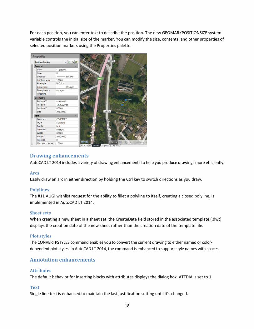
For each position, you can enter text to describe the position. The new GEOMARKPOSITIONSIZE system
variable controls the initial size of the marker. You can modify the size, contents, and other properties of
selected position markers using the Properties palette.
DrawingenhancementsAutoCAD LT 2014 includes a variety of drawing enhancements to help you produce drawings more efficiently.
ArcsEasily draw an arc in either direction by holding the Ctrl key to switch directions as you draw.
PolylinesThe #11 AUGI wishlist request for the ability to fillet a polyline to itself, creating a closed polyline, is
implemented in AutoCAD LT 2014.
SheetsetsWhen creating a new sheet in a sheet set, the CreateDate field stored in the associated template (.dwt)
displays the creation date of the new sheet rather than the creation date of the template file.
PlotstylesThe CONVERTPSTYLES command enables you to convert the current drawing to either named or color‐
dependent plot styles. In AutoCAD LT 2014, the command is enhanced to support style names with spaces.
Annotationenhancements
AttributesThe default behavior for inserting blocks with attributes displays the dialog box. ATTDIA is set to 1.
TextSingle line text is enhanced to maintain the last justification setting until it’s changed.
19
DimensionsThe new DIMCONTINUEMODE system variable provides you with more control when creating continued
and baseline dimensions. When DIMCONTINUE is set to 0, the DIMCONTINUE and DIMBASELINE
commands create dimensions based on the current dimension style. When set to 1, they apply the
dimension style of the selected dimension.
HatchThe Hatch tool on the ribbon maintains the previous method for selecting objects to hatch: Pick internal
point or Select objects. The Undo option is added to the command line.
ConnectionIn AutoCAD LT 2014 the Online ribbon tab is renamed Autodesk® 360. It includes a new Manage
Documents tool for easy access to the Autodesk 360 folder on your local machine, and the new Design
Feed enables you to enter posts and images for a drawing that can be shared online.
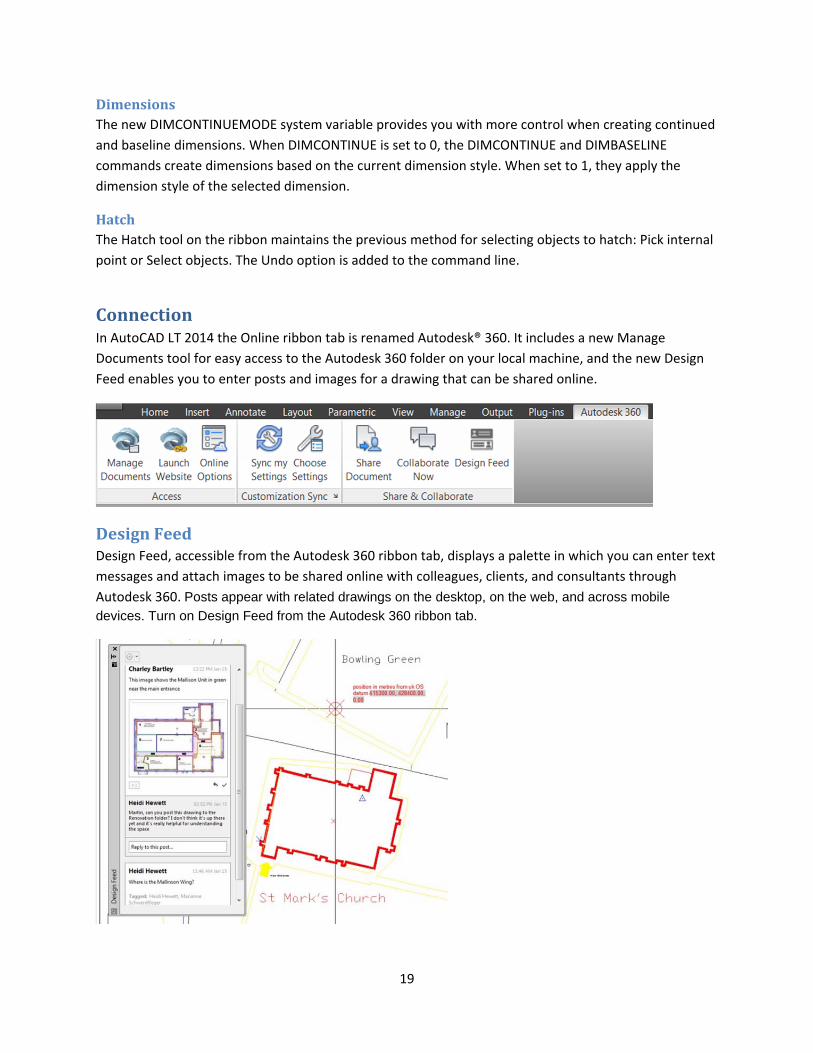
DesignFeedDesign Feed, accessible from the Autodesk 360 ribbon tab, displays a palette in which you can enter text
messages and attach images to be shared online with colleagues, clients, and consultants through
Autodesk 360. Posts appear with related drawings on the desktop, on the web, and across mobile
devices. Turn on Design Feed from the Autodesk 360 ribbon tab.
20
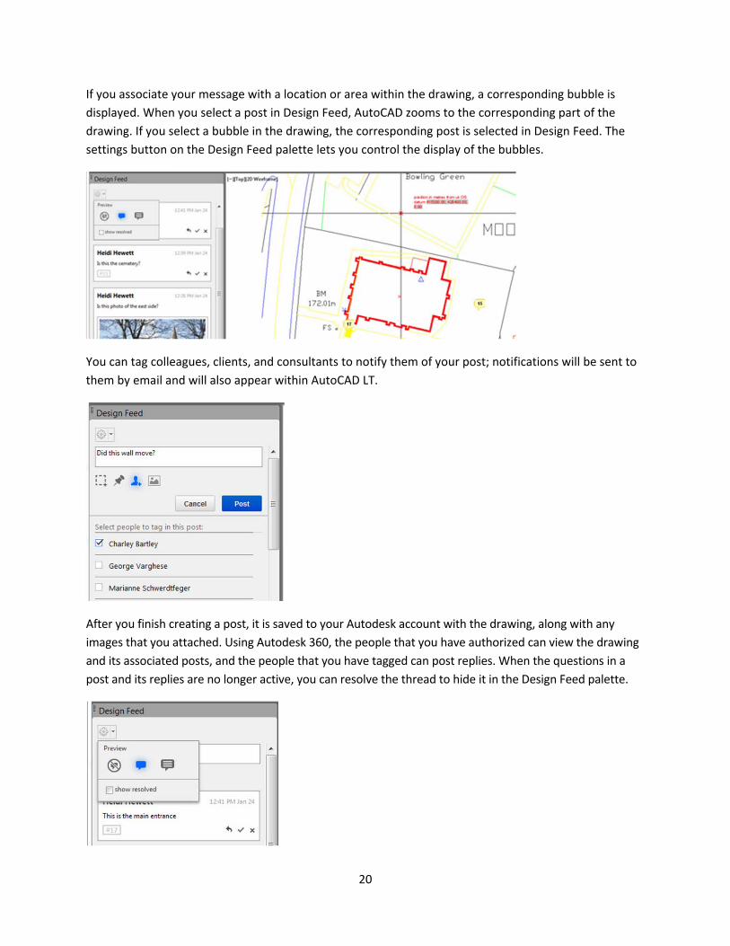
If you associate your message with a location or area within the drawing, a corresponding bubble is
displayed. When you select a post in Design Feed, AutoCAD zooms to the corresponding part of the
drawing. If you select a bubble in the drawing, the corresponding post is selected in Design Feed. The
settings button on the Design Feed palette lets you control the display of the bubbles.
You can tag colleagues, clients, and consultants to notify them of your post; notifications will be sent to
them by email and will also appear within AutoCAD LT.
After you finish creating a post, it is saved to your Autodesk account with the drawing, along with any
images that you attached. Using Autodesk 360, the people that you have authorized can view the drawing
and its associated posts, and the people that you have tagged can post replies. When the questions in a
post and its replies are no longer active, you can resolve the thread to hide it in the Design Feed palette.
21
Customization
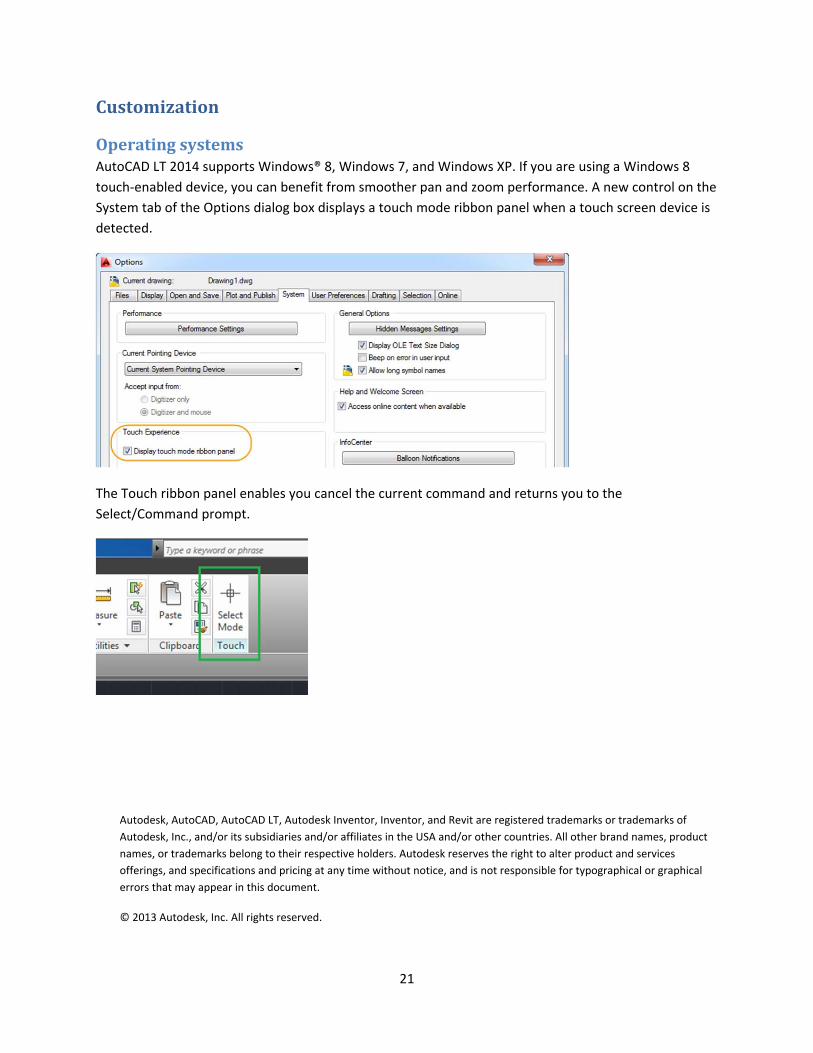
OperatingsystemsAutoCAD LT 2014 supports Windows® 8, Windows 7, and Windows XP. If you are using a Windows 8
touch‐enabled device, you can benefit from smoother pan and zoom performance. A new control on the
System tab of the Options dialog box displays a touch mode ribbon panel when a touch screen device is
detected.
The Touch ribbon panel enables you cancel the current command and returns you to the
Select/Command prompt.
Autodesk, AutoCAD, AutoCAD LT, Autodesk Inventor, Inventor, and Revit are registered trademarks or trademarks of
Autodesk, Inc., and/or its subsidiaries and/or affiliates in the USA and/or other countries. All other brand names, product
names, or trademarks belong to their respective holders. Autodesk reserves the right to alter product and services
offerings, and specifications and pricing at any time without notice, and is not responsible for typographical or graphical
errors that may appear in this document.
© 2013 Autodesk, Inc. All rights reserved.