AUTO TRANS DIAGNOSIS - A-140Ebgbonline.celicatech.com/89tech/auto trans diagnosis.pdf · AUTO TRANS...
30
AUTO TRANS DIAGNOSIS - A-140E 1988 Toyota Celica AUTOMATIC TRANSMISSIONS Toyota A-140E Electronic Controls APPLICATION APPLICATION TABLE Vehicle Application Transmission Model 1988-90 Camry ..................................... A-140E 1988-89 Celica .................................... A-140E DESCRIPTION The center of the Electronically Controlled Transmission/ Transaxle (ECT) is the Electronic Controlled Unit (ECU). The ECU receives information from various sensors and switches. Based on information received, the ECU generates output signals to control transmission operation. The ECU system controls shift points and operation of lock-up clutch. OPERATION * PLEASE READ THIS FIRST * The engine control system consists of an engine ECU, sensors, switches and solenoids. In order for the engine ECU to perform properly, it must be kept constantly informed of engine operating conditions. It is the task of the sensors to supply the engine ECU, via electrical signals, with specific information required to determine engine operating conditions. The engine ECU will then send electrical signals to the ECT ECU to control shift timing, lock-up timing, transfer shift timing (if equipped), self-diagnostic system, fluid temperature warning system and backup system. Individual component operation is as follows. NOTE: Unless otherwise specified, references in this article to ECU refer to the ECT ECU. ECU INPUT SENSORS Throttle Position (TP) Sensor The TP sensor is mounted on side of throttle body. The TP sensor senses throttle movement and position, and transmits an electrical signal to ECU. This signal determines gear shifting points. Vehicle Speed Sensor (VSS) This signal is picked up from a rotor on the output shaft and informs the ECU of road speed. The ECU uses sensor signals to control shift points and lock-up clutch operation. Transfer Shift Position Switch (TSPS) The switch signals the ECU that transfer shift lever has been shifted into "L4". When switch contact points are open, the ECU detects the lever is in "H2" or "H4" position, Pattern Select Switch (PSS)
Transcript of AUTO TRANS DIAGNOSIS - A-140Ebgbonline.celicatech.com/89tech/auto trans diagnosis.pdf · AUTO TRANS...
�AUTO TRANS DIAGNOSIS - A-140E
�1988 Toyota Celica
AUTOMATIC TRANSMISSIONS Toyota A-140E Electronic Controls
APPLICATION
APPLICATION TABLE�����������������������������������������������������������������������������������������������������������������������Vehicle Application Transmission Model
1988-90 Camry ..................................... A-140E1988-89 Celica .................................... A-140E�����������������������������������������������������������������������������������������������������������������������
DESCRIPTION
The center of the Electronically Controlled Transmission/Transaxle (ECT) is the Electronic Controlled Unit (ECU). The ECUreceives information from various sensors and switches. Based oninformation received, the ECU generates output signals to controltransmission operation. The ECU system controls shift points andoperation of lock-up clutch.
OPERATION
* PLEASE READ THIS FIRST *
The engine control system consists of an engine ECU, sensors,switches and solenoids. In order for the engine ECU to performproperly, it must be kept constantly informed of engine operatingconditions. It is the task of the sensors to supply the engine ECU,via electrical signals, with specific information required todetermine engine operating conditions. The engine ECU will then sendelectrical signals to the ECT ECU to control shift timing, lock-uptiming, transfer shift timing (if equipped), self-diagnostic system,fluid temperature warning system and backup system. Individualcomponent operation is as follows.
NOTE: Unless otherwise specified, references in this article to ECU refer to the ECT ECU.
ECU INPUT SENSORS
Throttle Position (TP) Sensor The TP sensor is mounted on side of throttle body. The TPsensor senses throttle movement and position, and transmits anelectrical signal to ECU. This signal determines gear shifting points.
Vehicle Speed Sensor (VSS) This signal is picked up from a rotor on the output shaft andinforms the ECU of road speed. The ECU uses sensor signals to controlshift points and lock-up clutch operation.
Transfer Shift Position Switch (TSPS) The switch signals the ECU that transfer shift lever has beenshifted into "L4". When switch contact points are open, the ECUdetects the lever is in "H2" or "H4" position,
Pattern Select Switch (PSS)
2 shift schedules are programmed into ECU: "Power" and"Normal" modes. The mode used by the ECU is determined by settingdriving pattern select switch.
Neutral Start Switch (NSS) The neutral start switch signals the ECU range selector leverposition. Switch contains contacts for both starts; control circuitand shift position indicator. The ECU uses signals from "2" and "L"range.
Brake Light Switch (BLS) The brake light switch signals the ECU whenever brakes areapplied. This signals the ECU whenever brakes are applied. Thissignals the ECU to disengage torque converter lock-up clutch.
OD Main Switch (ODMS) This switch causes transmission to shift in and out ofoverdrive. When OD main switch is "ON", current from battery flows toECU, causing transmission to be OD enabled. When OD main switch isturned off, current from the battery flows to ground.
Water Temperature Sensor (WTS) The sensor monitors engine coolant temperature. A signal istransmitted to ECU throughout entire range of operating temperatures.
Fluid Temperature Sensor (FTS) The fluid temperature sensor sends a signal to ECU thatvaries with transmission fluid temperatures.
Cruise Control Sensor (CCS) This sensor signals a Cruise Control ECU which preventstransmission from shifting into OD and prohibits lockup control whenvehicle speed drops below the drive set speed parameters.
Kickdown Switch (KS) This switch signals the ECU if the accelerator pedal isdepressed beyond the full throttle valve opening position.
Engine Speed Sensor (ESS) The engine speed sensor indicates engine RPM and sends asignal to the ECU.
OD Direct Clutch Speed Sensor (ODDCSS) The sensor senses the input shaft speed from 1-3 gear.
TESTING
DIAGNOSTIC PROCEDURE
1) Before testing transmission, ensure fluid level iscorrect, shift linkage, throttle cable, neutral switch and idle speedare correctly adjusted. Ensure transfer case linkage and transferswitch (if equipped) are correctly adjusted. Battery must be fullycharged for accurate testing. 2) To aid in fault diagnosis, determine if fault ishydraulic, electronic or a combination of both. 3) The electronic control is capable of storing self-diagnostic codes. To determine if a fault is electrical, read anystored diagnostic codes. Repair electrical fault associated with thecode. See DIAGNOSTIC CODES.
NOTE: Not all electrical faults will cause a diagnostic code to be
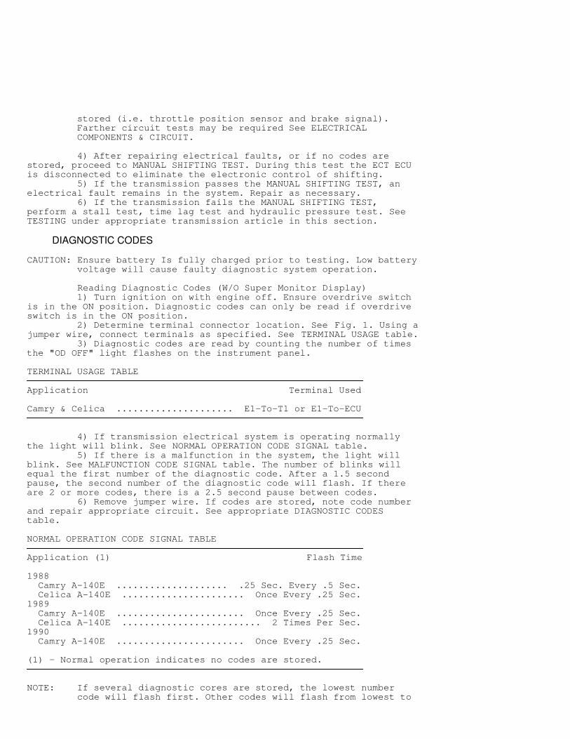
stored (i.e. throttle position sensor and brake signal). Farther circuit tests may be required See ELECTRICAL COMPONENTS & CIRCUIT.
4) After repairing electrical faults, or if no codes arestored, proceed to MANUAL SHIFTING TEST. During this test the ECT ECUis disconnected to eliminate the electronic control of shifting. 5) If the transmission passes the MANUAL SHIFTING TEST, anelectrical fault remains in the system. Repair as necessary. 6) If the transmission fails the MANUAL SHIFTING TEST,perform a stall test, time lag test and hydraulic pressure test. SeeTESTING under appropriate transmission article in this section.
DIAGNOSTIC CODES
CAUTION: Ensure battery Is fully charged prior to testing. Low battery voltage will cause faulty diagnostic system operation.
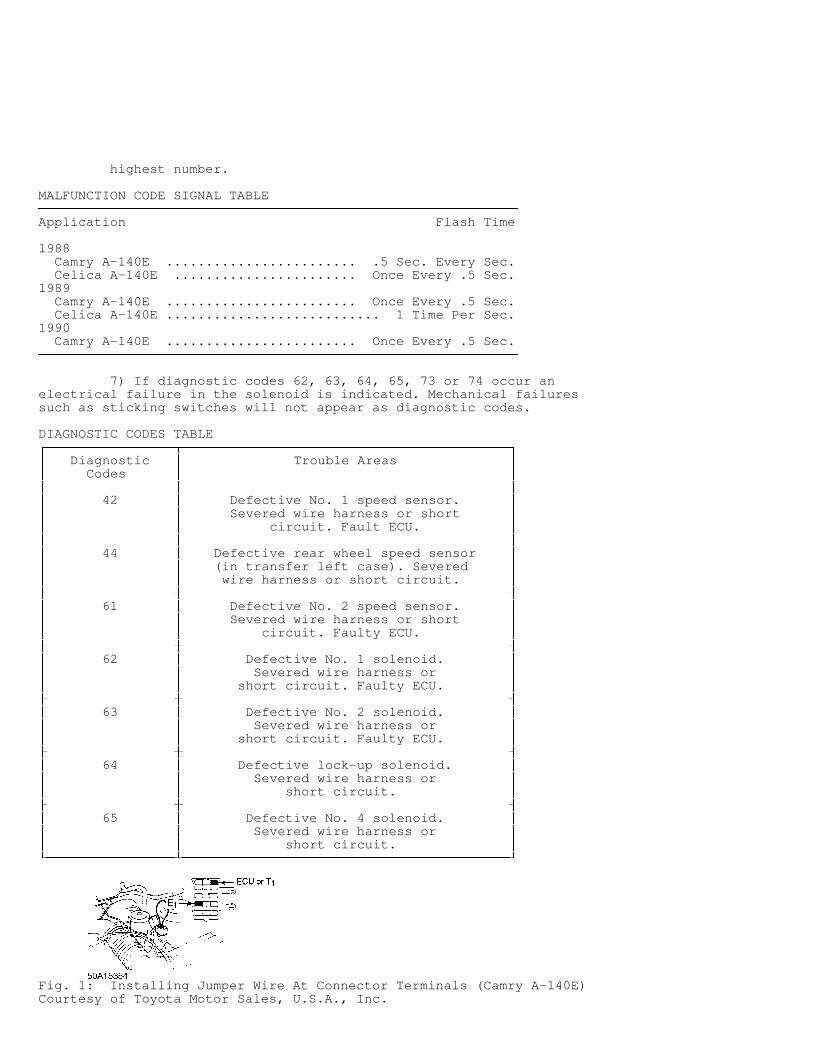
Reading Diagnostic Codes (W/O Super Monitor Display) 1) Turn ignition on with engine off. Ensure overdrive switchis in the ON position. Diagnostic codes can only be read if overdriveswitch is in the ON position. 2) Determine terminal connector location. See Fig. 1. Using ajumper wire, connect terminals as specified. See TERMINAL USAGE table. 3) Diagnostic codes are read by counting the number of timesthe "OD OFF" light flashes on the instrument panel.
TERMINAL USAGE TABLE�����������������������������������������������������������������������������������������������������������������������Application Terminal Used
Camry & Celica ..................... E1-To-T1 or E1-To-ECU�����������������������������������������������������������������������������������������������������������������������
4) If transmission electrical system is operating normallythe light will blink. See NORMAL OPERATION CODE SIGNAL table. 5) If there is a malfunction in the system, the light willblink. See MALFUNCTION CODE SIGNAL table. The number of blinks willequal the first number of the diagnostic code. After a 1.5 secondpause, the second number of the diagnostic code will flash. If thereare 2 or more codes, there is a 2.5 second pause between codes. 6) Remove jumper wire. If codes are stored, note code numberand repair appropriate circuit. See appropriate DIAGNOSTIC CODEStable.
NORMAL OPERATION CODE SIGNAL TABLE�����������������������������������������������������������������������������������������������������������������������Application (1) Flash Time
1988 Camry A-140E .................... .25 Sec. Every .5 Sec. Celica A-140E ...................... Once Every .25 Sec.1989 Camry A-140E ....................... Once Every .25 Sec. Celica A-140E ......................... 2 Times Per Sec.1990 Camry A-140E ....................... Once Every .25 Sec.
(1) - Normal operation indicates no codes are stored.�����������������������������������������������������������������������������������������������������������������������
NOTE: If several diagnostic cores are stored, the lowest number code will flash first. Other codes will flash from lowest to
highest number.
MALFUNCTION CODE SIGNAL TABLE�����������������������������������������������������������������������������������������������������������������������Application Flash Time
1988 Camry A-140E ........................ .5 Sec. Every Sec. Celica A-140E ....................... Once Every .5 Sec.1989 Camry A-140E ........................ Once Every .5 Sec. Celica A-140E ........................... 1 Time Per Sec.1990 Camry A-140E ........................ Once Every .5 Sec.�����������������������������������������������������������������������������������������������������������������������
7) If diagnostic codes 62, 63, 64, 65, 73 or 74 occur anelectrical failure in the solenoid is indicated. Mechanical failuressuch as sticking switches will not appear as diagnostic codes.
DIAGNOSTIC CODES TABLE������������������������������������������������������������������������������������������������������������������������ Diagnostic
� Trouble Areas
�� Codes
�
�� ��������������������������������������������������������������������������������������������������������������������� 42
� Defective No. 1 speed sensor.
��
� Severed wire harness or short
��
� circuit. Fault ECU.
�� ��������������������������������������������������������������������������������������������������������������������� 44
� Defective rear wheel speed sensor
��
� (in transfer left case). Severed
��
� wire harness or short circuit.
�� ��������������������������������������������������������������������������������������������������������������������� 61
� Defective No. 2 speed sensor.
��
� Severed wire harness or short
��
� circuit. Faulty ECU.
�� ��������������������������������������������������������������������������������������������������������������������� 62
� Defective No. 1 solenoid.
��
� Severed wire harness or
��
� short circuit. Faulty ECU.
�� ��������������������������������������������������������������������������������������������������������������������� 63
� Defective No. 2 solenoid.
��
� Severed wire harness or
��
� short circuit. Faulty ECU.
�� ��������������������������������������������������������������������������������������������������������������������� 64
� Defective lock-up solenoid.
��
� Severed wire harness or
��
� short circuit.
�� ��������������������������������������������������������������������������������������������������������������������� 65
� Defective No. 4 solenoid.
��
� Severed wire harness or
��
� short circuit.
� ���������������������������������������������������������������������������������������������������������������������
Fig. 1: Installing Jumper Wire At Connector Terminals (Camry A-140E)Courtesy of Toyota Motor Sales, U.S.A., Inc.
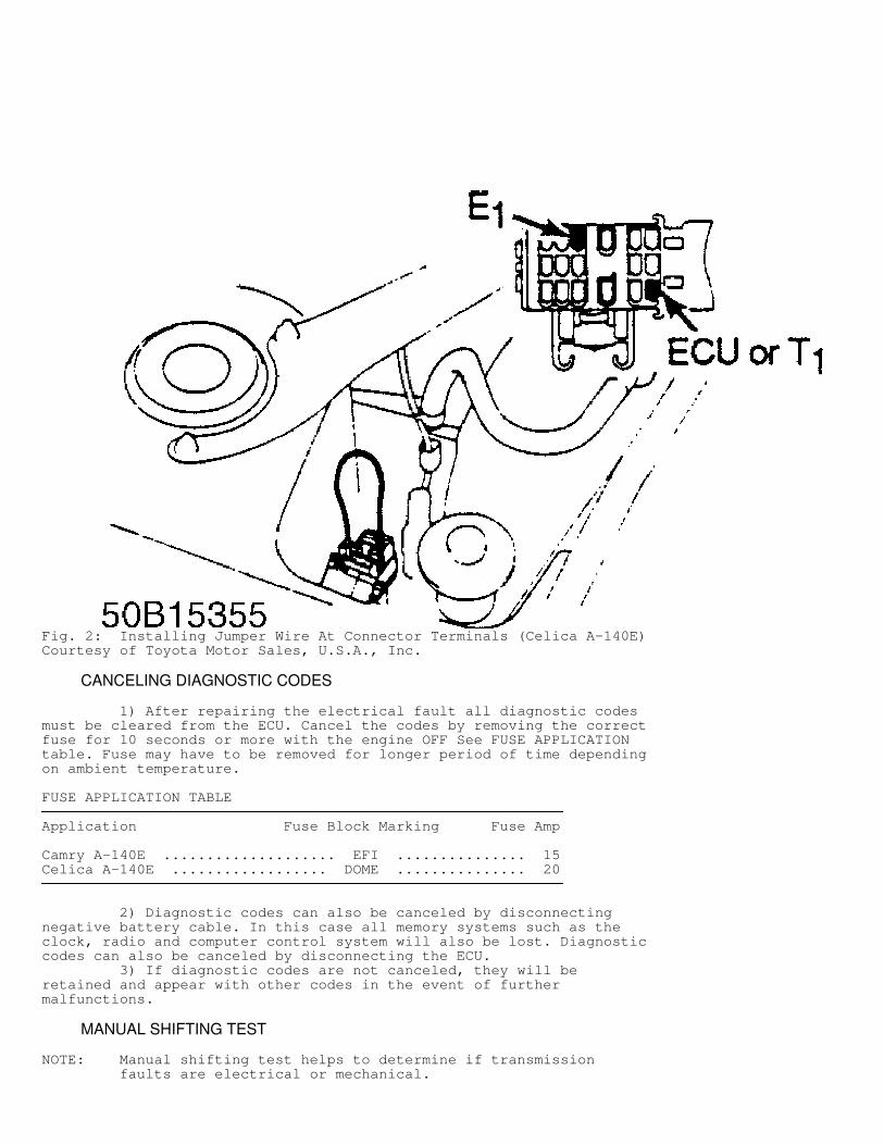
Fig. 2: Installing Jumper Wire At Connector Terminals (Celica A-140E)Courtesy of Toyota Motor Sales, U.S.A., Inc.
CANCELING DIAGNOSTIC CODES
1) After repairing the electrical fault all diagnostic codesmust be cleared from the ECU. Cancel the codes by removing the correctfuse for 10 seconds or more with the engine OFF See FUSE APPLICATIONtable. Fuse may have to be removed for longer period of time dependingon ambient temperature.
FUSE APPLICATION TABLE�����������������������������������������������������������������������������������������������������������������������Application Fuse Block Marking Fuse Amp
Camry A-140E .................... EFI ............... 15Celica A-140E .................. DOME ............... 20�����������������������������������������������������������������������������������������������������������������������
2) Diagnostic codes can also be canceled by disconnectingnegative battery cable. In this case all memory systems such as theclock, radio and computer control system will also be lost. Diagnosticcodes can also be canceled by disconnecting the ECU. 3) If diagnostic codes are not canceled, they will beretained and appear with other codes in the event of furthermalfunctions.
MANUAL SHIFTING TEST
NOTE: Manual shifting test helps to determine if transmission faults are electrical or mechanical.
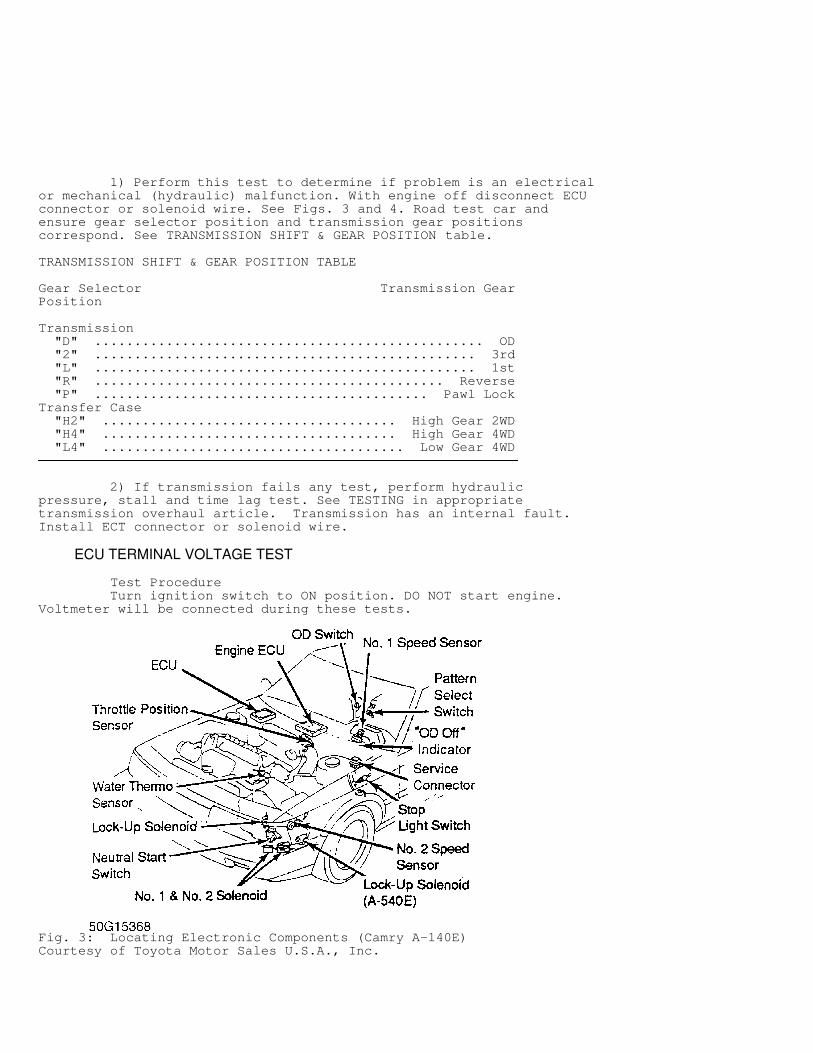
1) Perform this test to determine if problem is an electricalor mechanical (hydraulic) malfunction. With engine off disconnect ECUconnector or solenoid wire. See Figs. 3 and 4. Road test car andensure gear selector position and transmission gear positionscorrespond. See TRANSMISSION SHIFT & GEAR POSITION table.
TRANSMISSION SHIFT & GEAR POSITION TABLE�����������������������������������������������������������������������������������������������������������������������Gear Selector Transmission GearPosition
Transmission "D" ................................................. OD "2" ................................................ 3rd "L" ................................................ 1st "R" ............................................ Reverse "P" .......................................... Pawl LockTransfer Case "H2" ..................................... High Gear 2WD "H4" ..................................... High Gear 4WD "L4" ...................................... Low Gear 4WD�����������������������������������������������������������������������������������������������������������������������
2) If transmission fails any test, perform hydraulicpressure, stall and time lag test. See TESTING in appropriatetransmission overhaul article. Transmission has an internal fault.Install ECT connector or solenoid wire.
ECU TERMINAL VOLTAGE TEST
Test Procedure Turn ignition switch to ON position. DO NOT start engine.Voltmeter will be connected during these tests.
Fig. 3: Locating Electronic Components (Camry A-140E)Courtesy of Toyota Motor Sales U.S.A., Inc.
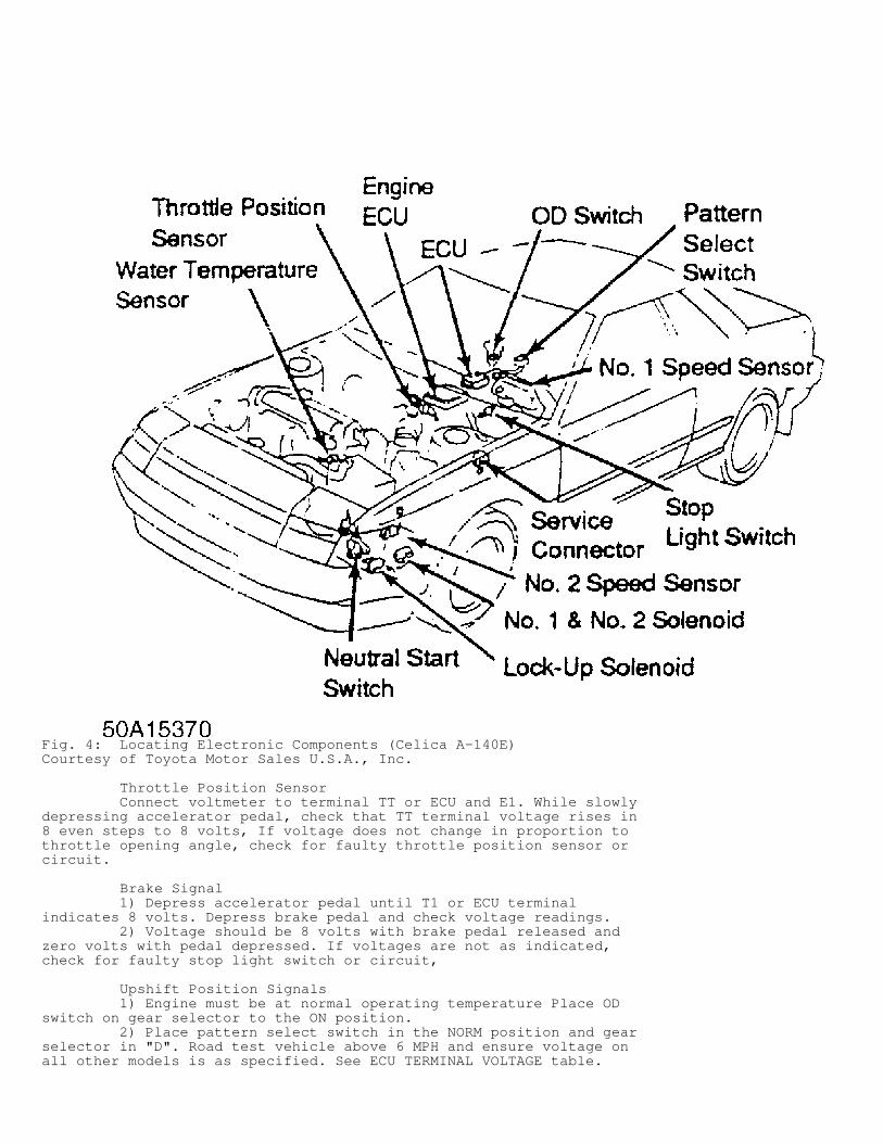
Fig. 4: Locating Electronic Components (Celica A-140E)Courtesy of Toyota Motor Sales U.S.A., Inc.
Throttle Position Sensor Connect voltmeter to terminal TT or ECU and E1. While slowlydepressing accelerator pedal, check that TT terminal voltage rises in8 even steps to 8 volts, If voltage does not change in proportion tothrottle opening angle, check for faulty throttle position sensor orcircuit.
Brake Signal 1) Depress accelerator pedal until T1 or ECU terminalindicates 8 volts. Depress brake pedal and check voltage readings. 2) Voltage should be 8 volts with brake pedal released andzero volts with pedal depressed. If voltages are not as indicated,check for faulty stop light switch or circuit,
Upshift Position Signals 1) Engine must be at normal operating temperature Place ODswitch on gear selector to the ON position. 2) Place pattern select switch in the NORM position and gearselector in "D". Road test vehicle above 6 MPH and ensure voltage onall other models is as specified. See ECU TERMINAL VOLTAGE table.
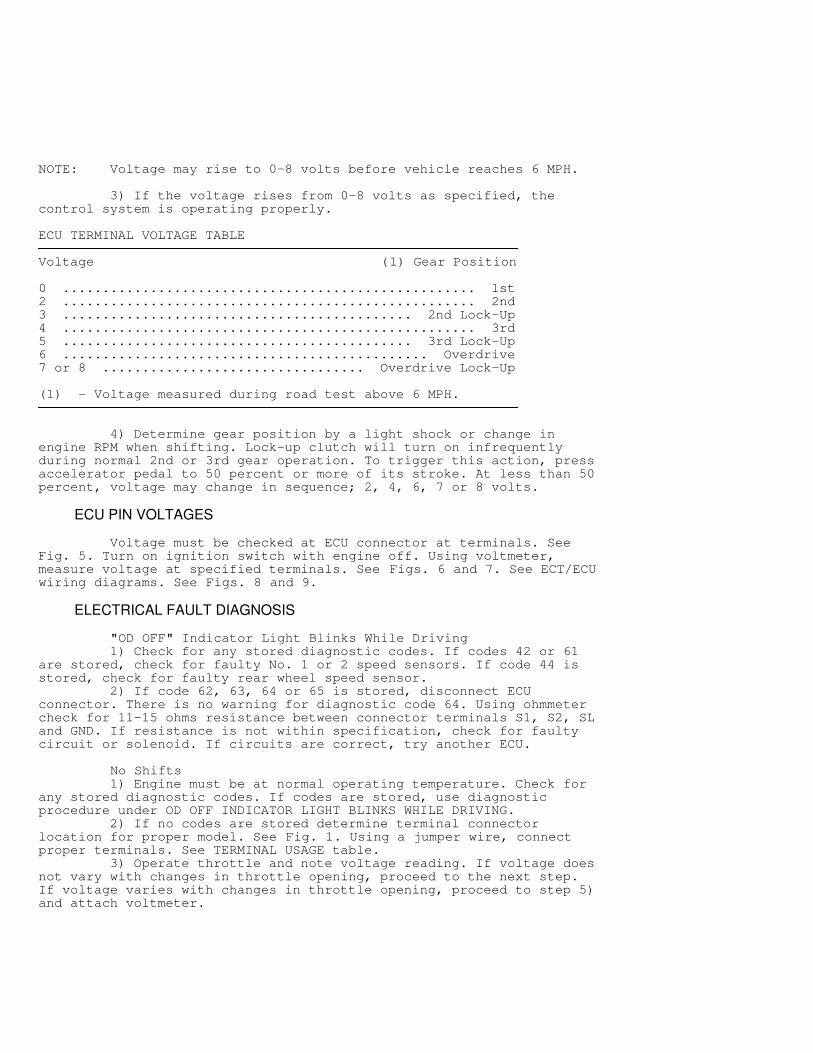
NOTE: Voltage may rise to 0-8 volts before vehicle reaches 6 MPH.
3) If the voltage rises from 0-8 volts as specified, thecontrol system is operating properly.
ECU TERMINAL VOLTAGE TABLE�����������������������������������������������������������������������������������������������������������������������Voltage (1) Gear Position
0 .................................................... 1st2 .................................................... 2nd3 ............................................ 2nd Lock-Up4 .................................................... 3rd5 ............................................ 3rd Lock-Up6 .............................................. Overdrive7 or 8 ................................. Overdrive Lock-Up
(1) - Voltage measured during road test above 6 MPH.�����������������������������������������������������������������������������������������������������������������������
4) Determine gear position by a light shock or change inengine RPM when shifting. Lock-up clutch will turn on infrequentlyduring normal 2nd or 3rd gear operation. To trigger this action, pressaccelerator pedal to 50 percent or more of its stroke. At less than 50percent, voltage may change in sequence; 2, 4, 6, 7 or 8 volts.
ECU PIN VOLTAGES
Voltage must be checked at ECU connector at terminals. SeeFig. 5. Turn on ignition switch with engine off. Using voltmeter,measure voltage at specified terminals. See Figs. 6 and 7. See ECT/ECUwiring diagrams. See Figs. 8 and 9.
ELECTRICAL FAULT DIAGNOSIS
"OD OFF" Indicator Light Blinks While Driving 1) Check for any stored diagnostic codes. If codes 42 or 61are stored, check for faulty No. 1 or 2 speed sensors. If code 44 isstored, check for faulty rear wheel speed sensor. 2) If code 62, 63, 64 or 65 is stored, disconnect ECUconnector. There is no warning for diagnostic code 64. Using ohmmetercheck for 11-15 ohms resistance between connector terminals S1, S2, SLand GND. If resistance is not within specification, check for faultycircuit or solenoid. If circuits are correct, try another ECU.
No Shifts 1) Engine must be at normal operating temperature. Check forany stored diagnostic codes. If codes are stored, use diagnosticprocedure under OD OFF INDICATOR LIGHT BLINKS WHILE DRIVING. 2) If no codes are stored determine terminal connectorlocation for proper model. See Fig. 1. Using a jumper wire, connectproper terminals. See TERMINAL USAGE table. 3) Operate throttle and note voltage reading. If voltage doesnot vary with changes in throttle opening, proceed to the next step.If voltage varies with changes in throttle opening, proceed to step 5)and attach voltmeter.
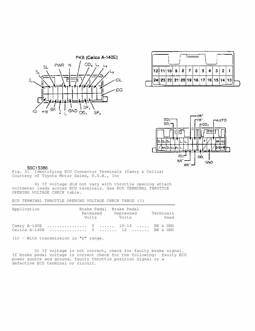
Fig. 5: Identifying ECU Connector Terminals (Camry & Celica)Courtesy of Toyota Motor Sales, U.S.A., Inc
4) If voltage did not vary with throttle opening attachvoltmeter leads across ECU terminals. See ECU TERMINAL THROTTLEOPENING VOLTAGE CHECK table.
ECU TERMINAL THROTTLE OPENING VOLTAGE CHECK TABLE (1)���������������������������������������������������������������������������������������������������������������������������������Application Brake Pedal Brake Pedal Released Depressed Terminals Volts Volts Used
Camry A-140E ................ 0 ...... 10-14 ..... BK & GNDCelica A-140E ............... 0 ....... 12 ....... BK & GND
(1) - With transmission in "D" range.���������������������������������������������������������������������������������������������������������������������������������
5) If voltage is not correct, check for faulty brake signal.If brake pedal voltage is correct check for the following: faulty ECUpower source and ground, faulty throttle position signal or adefective ECU terminal or circuit.
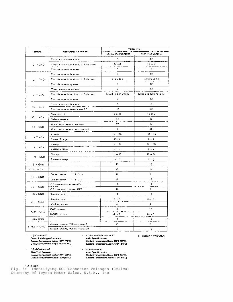
Fig. 6: Identifying ECU Connector Voltages (Celica)Courtesy of Toyota Motor Sales, U.S.A., Inc
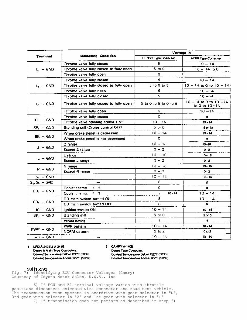
Fig. 7: Identifying ECU Connector Voltages (Camry)Courtesy of Toyota Motor Sales, U.S.A., Inc
6) If ECU and E1 terminal voltage varies with throttlepositions disconnect solenoid wire connector and road test vehicle.The transmission must operate in overdrive with gear selector in "D",3rd gear with selector in "2" and 1st gear with selector in "L". 7) If transmission does not perform as described in step 6)
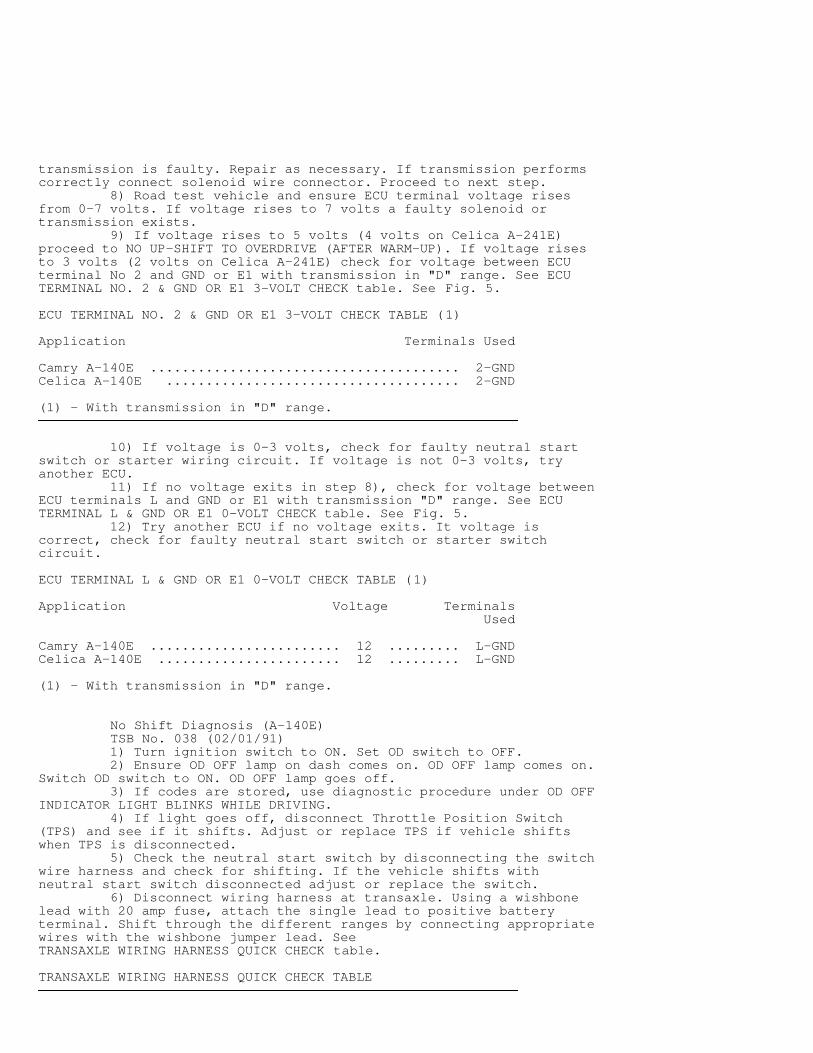
transmission is faulty. Repair as necessary. If transmission performscorrectly connect solenoid wire connector. Proceed to next step. 8) Road test vehicle and ensure ECU terminal voltage risesfrom 0-7 volts. If voltage rises to 7 volts a faulty solenoid ortransmission exists. 9) If voltage rises to 5 volts (4 volts on Celica A-241E)proceed to NO UP-SHIFT TO OVERDRIVE (AFTER WARM-UP). If voltage risesto 3 volts (2 volts on Celica A-241E) check for voltage between ECUterminal No 2 and GND or E1 with transmission in "D" range. See ECUTERMINAL NO. 2 & GND OR E1 3-VOLT CHECK table. See Fig. 5.
ECU TERMINAL NO. 2 & GND OR E1 3-VOLT CHECK TABLE (1)�����������������������������������������������������������������������������������������������������������������������Application Terminals Used
Camry A-140E ....................................... 2-GNDCelica A-140E ..................................... 2-GND
(1) - With transmission in "D" range.�����������������������������������������������������������������������������������������������������������������������
10) If voltage is 0-3 volts, check for faulty neutral startswitch or starter wiring circuit. If voltage is not 0-3 volts, tryanother ECU. 11) If no voltage exits in step 8), check for voltage betweenECU terminals L and GND or E1 with transmission "D" range. See ECUTERMINAL L & GND OR E1 0-VOLT CHECK table. See Fig. 5. 12) Try another ECU if no voltage exits. It voltage iscorrect, check for faulty neutral start switch or starter switchcircuit.
ECU TERMINAL L & GND OR E1 0-VOLT CHECK TABLE (1)�����������������������������������������������������������������������������������������������������������������������Application Voltage Terminals Used
Camry A-140E ........................ 12 ......... L-GNDCelica A-140E ....................... 12 ......... L-GND
(1) - With transmission in "D" range.�����������������������������������������������������������������������������������������������������������������������
No Shift Diagnosis (A-140E) TSB No. 038 (02/01/91) 1) Turn ignition switch to ON. Set OD switch to OFF. 2) Ensure OD OFF lamp on dash comes on. OD OFF lamp comes on.Switch OD switch to ON. OD OFF lamp goes off. 3) If codes are stored, use diagnostic procedure under OD OFFINDICATOR LIGHT BLINKS WHILE DRIVING. 4) If light goes off, disconnect Throttle Position Switch(TPS) and see if it shifts. Adjust or replace TPS if vehicle shiftswhen TPS is disconnected. 5) Check the neutral start switch by disconnecting the switchwire harness and check for shifting. If the vehicle shifts withneutral start switch disconnected adjust or replace the switch. 6) Disconnect wiring harness at transaxle. Using a wishbonelead with 20 amp fuse, attach the single lead to positive batteryterminal. Shift through the different ranges by connecting appropriatewires with the wishbone jumper lead. SeeTRANSAXLE WIRING HARNESS QUICK CHECK table.
TRANSAXLE WIRING HARNESS QUICK CHECK TABLE�����������������������������������������������������������������������������������������������������������������������
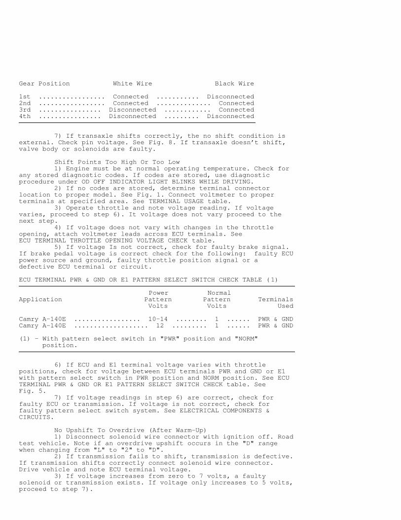
Gear Position White Wire Black Wire
1st ................. Connected ........... Disconnected2nd ................. Connected .............. Connected3rd ................ Disconnected ............ Connected4th ................ Disconnected ......... Disconnected�����������������������������������������������������������������������������������������������������������������������
7) If transaxle shifts correctly, the no shift condition isexternal. Check pin voltage. See Fig. 8. If transaxle doesn’t shift,valve body or solenoids are faulty.
Shift Points Too High Or Too Low 1) Engine must be at normal operating temperature. Check forany stored diagnostic codes. If codes are stored, use diagnosticprocedure under OD OFF INDICATOR LIGHT BLINKS WHILE DRIVING. 2) If no codes are stored, determine terminal connectorlocation to proper model. See Fig. 1. Connect voltmeter to properterminals at specified area. See TERMINAL USAGE table. 3) Operate throttle and note voltage reading. If voltagevaries, proceed to step 6). It voltage does not vary proceed to thenext step. 4) If voltage does not vary with changes in the throttleopening, attach voltmeter leads across ECU terminals. SeeECU TERMINAL THROTTLE OPENING VOLTAGE CHECK table. 5) If voltage Is not correct, check for faulty brake signal.If brake pedal voltage is correct check for the following: faulty ECUpower source and ground, faulty throttle position signal or adefective ECU terminal or circuit.
ECU TERMINAL PWR & GND OR E1 PATTERN SELECT SWITCH CHECK TABLE (1)������������������������������������������������������������������������������������������������������������������������������������������� Power NormalApplication Pattern Pattern Terminals Volts Volts Used
Camry A-140E ................. 10-14 ........ 1 ...... PWR & GNDCamry A-140E ................... 12 ......... 1 ...... PWR & GND
(1) - With pattern select switch in "PWR" position and "NORM" position.�������������������������������������������������������������������������������������������������������������������������������������������
6) If ECU and E1 terminal voltage varies with throttlepositions, check for voltage between ECU terminals PWR and GND or E1with pattern select switch in PWR position and NORM position. See ECUTERMINAL PWR & GND OR E1 PATTERN SELECT SWITCH CHECK table. SeeFig. 5. 7) If voltage readings in step 6) are correct, check forfaulty ECU or transmission. If voltage is not correct, check forfaulty pattern select switch system. See ELECTRICAL COMPONENTS &CIRCUITS.
No Upshift To Overdrive (After Warm-Up) 1) Disconnect solenoid wire connector with ignition off. Roadtest vehicle. Note if an overdrive upshift occurs in the "D" rangewhen changing from "L" to "2" to "D". 2) If transmission fails to shift, transmission is defective.If transmission shifts correctly connect solenoid wire connector.Drive vehicle and note ECU terminal voltage. 3) If voltage increases from zero to 7 volts, a faultysolenoid or transmission exists. If voltage only increases to 5 volts,proceed to step 7).
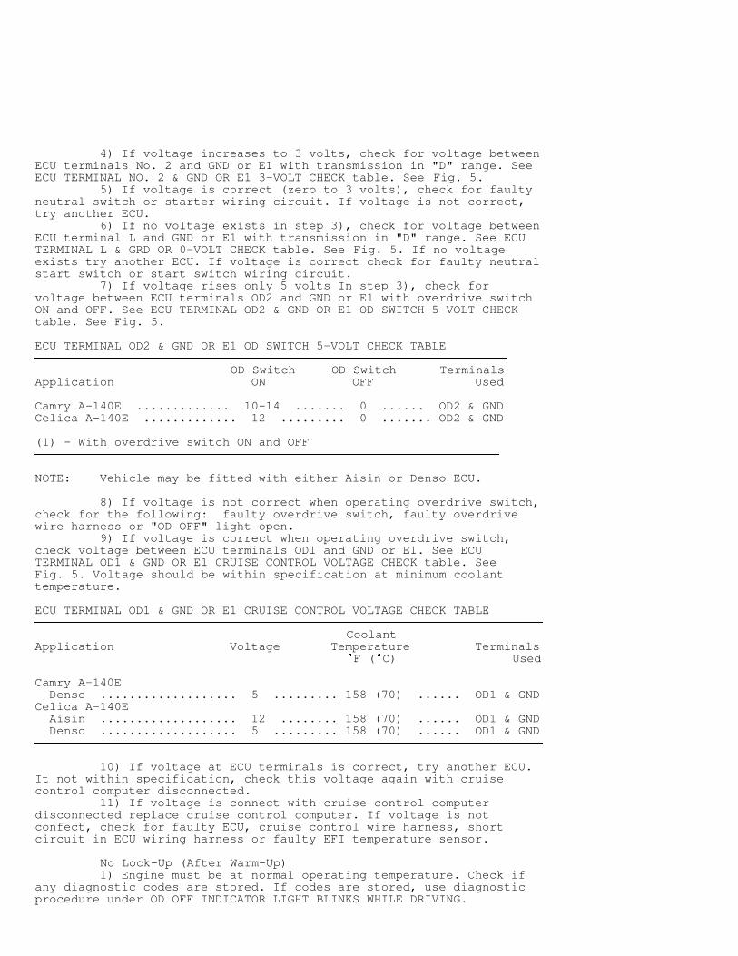
4) If voltage increases to 3 volts, check for voltage betweenECU terminals No. 2 and GND or E1 with transmission in "D" range. SeeECU TERMINAL NO. 2 & GND OR E1 3-VOLT CHECK table. See Fig. 5. 5) If voltage is correct (zero to 3 volts), check for faultyneutral switch or starter wiring circuit. If voltage is not correct,try another ECU. 6) If no voltage exists in step 3), check for voltage betweenECU terminal L and GND or E1 with transmission in "D" range. See ECUTERMINAL L & GRD OR 0-VOLT CHECK table. See Fig. 5. If no voltageexists try another ECU. If voltage is correct check for faulty neutralstart switch or start switch wiring circuit. 7) If voltage rises only 5 volts In step 3), check forvoltage between ECU terminals OD2 and GND or E1 with overdrive switchON and OFF. See ECU TERMINAL OD2 & GND OR E1 OD SWITCH 5-VOLT CHECKtable. See Fig. 5.
ECU TERMINAL OD2 & GND OR E1 OD SWITCH 5-VOLT CHECK TABLE��������������������������������������������������������������������������������������������������������������������������������� OD Switch OD Switch TerminalsApplication ON OFF Used
Camry A-140E ............. 10-14 ....... 0 ...... OD2 & GNDCelica A-140E ............. 12 ......... 0 ....... OD2 & GND
(1) - With overdrive switch ON and OFF�������������������������������������������������������������������������������������������������������������������������������
NOTE: Vehicle may be fitted with either Aisin or Denso ECU.
8) If voltage is not correct when operating overdrive switch,check for the following: faulty overdrive switch, faulty overdrivewire harness or "OD OFF" light open. 9) If voltage is correct when operating overdrive switch,check voltage between ECU terminals OD1 and GND or E1. See ECUTERMINAL OD1 & GND OR E1 CRUISE CONTROL VOLTAGE CHECK table. SeeFig. 5. Voltage should be within specification at minimum coolanttemperature.
ECU TERMINAL OD1 & GND OR E1 CRUISE CONTROL VOLTAGE CHECK TABLE������������������������������������������������������������������������������������������������������������������������������������������� CoolantApplication Voltage Temperature Terminals F ( C) Used
Camry A-140E Denso ................... 5 ......... 158 (70) ...... OD1 & GNDCelica A-140E Aisin ................... 12 ........ 158 (70) ...... OD1 & GND Denso ................... 5 ......... 158 (70) ...... OD1 & GND�������������������������������������������������������������������������������������������������������������������������������������������
10) If voltage at ECU terminals is correct, try another ECU.It not within specification, check this voltage again with cruisecontrol computer disconnected. 11) If voltage is connect with cruise control computerdisconnected replace cruise control computer. If voltage is notconfect, check for faulty ECU, cruise control wire harness, shortcircuit in ECU wiring harness or faulty EFI temperature sensor.
No Lock-Up (After Warm-Up) 1) Engine must be at normal operating temperature. Check ifany diagnostic codes are stored. If codes are stored, use diagnosticprocedure under OD OFF INDICATOR LIGHT BLINKS WHILE DRIVING.
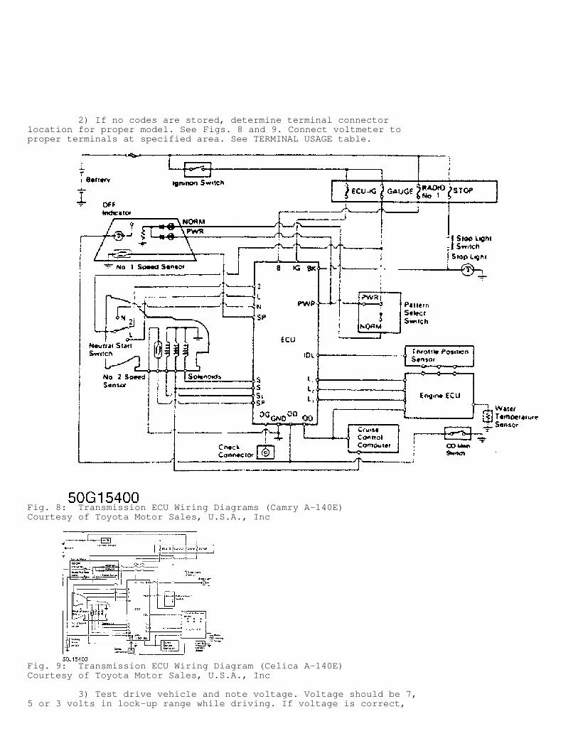
2) If no codes are stored, determine terminal connectorlocation for proper model. See Figs. 8 and 9. Connect voltmeter toproper terminals at specified area. See TERMINAL USAGE table.
Fig. 8: Transmission ECU Wiring Diagrams (Camry A-140E)Courtesy of Toyota Motor Sales, U.S.A., Inc
Fig. 9: Transmission ECU Wiring Diagram (Celica A-140E)Courtesy of Toyota Motor Sales, U.S.A., Inc
3) Test drive vehicle and note voltage. Voltage should be 7,5 or 3 volts in lock-up range while driving. If voltage is correct,
check for the following: faulty transmission, seized lock-up solenoidor faulty lock-up mechanism. 4) If there is not 7, 5 or 3 volts in lock-up range whiledriving, check for voltage between ECU terminals BK or STP or TT andGND or E1 with brake pedal depressed. SeeECU TERMINAL THROTTLE OPENING VOLTAGE CHECK table. 5) If voltages are incorrect when operating brake pedal checkfor faulty brake signal. On all models except Pickup and 4Runner A-340H, if voltages are correct when operating brake pedal check forfaulty ECU power source and ground or faulty throttle position signal.
ELECTRICAL COMPONENTS & CIRCUITS
CAUTION: Ensure cruise control is off while testing voltages. Some models may use Aisin or Denso type ECU computer.
Transmission Solenoid Circuit 1) Ensure engine is not punning. Disconnect connector fromengine ECU. Measure resistance between terminals S1, S2, SL and groundof ECU connector. 2) Resistance should be 11-15 ohms. This checks the solenoidsand solenoid wiring. Apply battery voltage to the solenoid circuits.An audible click should be heard when the solenoid engages.
CAUTION: If solenoid is blocked with dirt; there will be no fluid control even though solenoid operates with battery voltage applied.
3) Apply 71 psi (5 kg/cm � ) of compressed air and check thatsolenoid valves do not leak air. 4) Proper solenoids must be applied or released in thecorrect gear application. See Fig. 10.
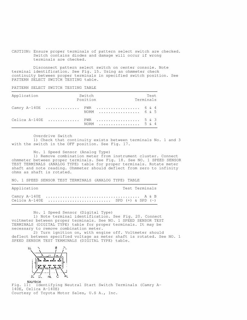
Neutral Start Switch Determine neutral start switch terminal identification. SeeFig. 11. Check for continuity at specified terminals in appropriategear position. See NEUTRAL START SWITCH CONTINUITY table.
NEUTRAL START SWITCH CONTINUITY TABLE�����������������������������������������������������������������������������������������������������������������������Gear ContinuityShift BetweenPosition Terminals
Camry A-140E "N" Range ....................................... NL & C "2" Range ....................................... 2L & C "L" Range ....................................... LL & CCelica A-140E "P" Range ................................. B & N/C & PL "R" Range ....................................... C & RL "N" Range ................................. B & N/C & NL "D" Range ....................................... C & DL "2" Range ....................................... C & 2L "L" Range ....................................... C & LL�����������������������������������������������������������������������������������������������������������������������
Throttle Position Sensor 1) With engine off, unplug throttle position sensor. Noteterminal identification. See Fig. 12. Check resistance readings atspecified terminals. See THROTTLE POSITION SENSOR CIRCUIT RESISTANCEtable.
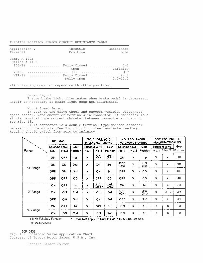
THROTTLE POSITION SENSOR CIRCUIT RESISTANCE TABLE�����������������������������������������������������������������������������������������������������������������������Application & Throttle ResistanceTerminal Position ohms
Camry A-140E Celica A-140E IDL/E2 ............... Fully Closed .............. 0-1 Open Infinity VC/E2 .................... (1) ................... 3-7 VTA/E2 ............... Fully Closed ............ .2-.8 Fully Open 3.3-10.0
(1) - Reading does not depend on throttle position.�����������������������������������������������������������������������������������������������������������������������
Brake Signal Ensure brake light illuminates when brake pedal is depressed.Repair as necessary if brake light does not illuminate.
No. 2 Speed Sensor 1) Jack up one drive wheel and support vehicle. Disconnectspeed sensor. Note amount of terminals in connector. If connector is asingle terminal type connect ohmmeter between connector and ground.See Fig. 13. 2) If connector is a double terminal type connect ohmmeterbetween both terminals. See Fig. 13. Spin wheel and note reading.Reading should switch from zero to infinity.
Fig. 10: Solenoid Valve Application ChartCourtesy of Toyota Motor Sales, U.S A., Inc.
Pattern Select Switch
CAUTION: Ensure proper terminals of pattern select switch are checked. Switch contains diodes and damage will occur if wrong terminals are checked.
Disconnect pattern select switch on center console. Noteterminal identification. See Fig. 15. Using an ohmmeter checkcontinuity between proper terminals in specified switch position. SeePATTERN SELECT SWITCH TESTING table.
PATTERN SELECT SWITCH TESTING TABLE�����������������������������������������������������������������������������������������������������������������������Application Switch Test Position Terminals
Camry A-140E .............. PWR .................. 6 & 4 NORM ................. 6 & 5
Celica A-140E ............. PWR .................. 5 & 3 NORM ................. 5 & 4�����������������������������������������������������������������������������������������������������������������������
Overdrive Switch 1) Check that continuity exists between terminals No. 1 and 3with the switch in the OFF position. See Fig. 17.
No. 1 Speed Sensor (Analog Type) 1) Remove combination meter from instrument cluster. Connectohmmeter between proper terminals. See Fig. 18. See NO. 1 SPEED SENSORTEST TERMINALS (ANALOG TYPE) table for proper terminals. Rotate metershaft and note reading. Ohmmeter should deflect from zero to infinityohms as shaft is rotated.
NO. 1 SPEED SENSOR TEST TERMINALS (ANALOG TYPE) TABLE�����������������������������������������������������������������������������������������������������������������������Application Test Terminals
Camry A-140E ....................................... A & BCelica A-140E .......................... SPD (+) & SPD (-)�����������������������������������������������������������������������������������������������������������������������
No. 1 Speed Sensor (Digital Type) 1) Note terminal identification. See Fig. 20. Connectvoltmeter between proper terminals. See NO. 1 SPEED SENSOR TESTTERMINALS (DIGITAL TYPE) table for proper terminals. It may benecessary to remove combination meter. 2) Turn ignition on, with engine off. Voltmeter shoulddeflect between specified voltage as meter shaft is rotated. See NO. 1SPEED SENSOR TEST TERMINALS (DIGITAL TYPE) table.
Fig. 11: Identifying Neutral Start Switch Terminals (Camry A-140E, Celica A-140E)Courtesy of Toyota Motor Sales, U.S A., Inc.
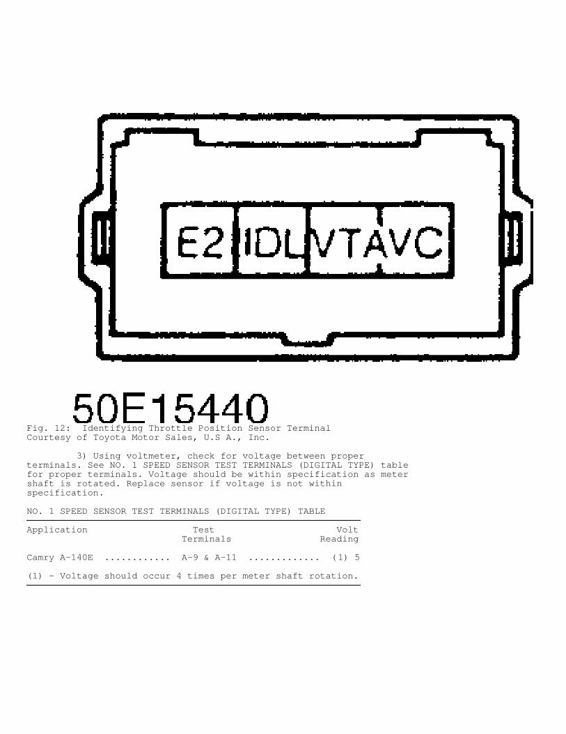
Fig. 12: Identifying Throttle Position Sensor TerminalCourtesy of Toyota Motor Sales, U.S A., Inc.
3) Using voltmeter, check for voltage between properterminals. See NO. 1 SPEED SENSOR TEST TERMINALS (DIGITAL TYPE) tablefor proper terminals. Voltage should be within specification as metershaft is rotated. Replace sensor if voltage is not withinspecification.
NO. 1 SPEED SENSOR TEST TERMINALS (DIGITAL TYPE) TABLE�����������������������������������������������������������������������������������������������������������������������Application Test Volt Terminals Reading
Camry A-140E ............ A-9 & A-11 ............. (1) 5
(1) - Voltage should occur 4 times per meter shaft rotation.�����������������������������������������������������������������������������������������������������������������������
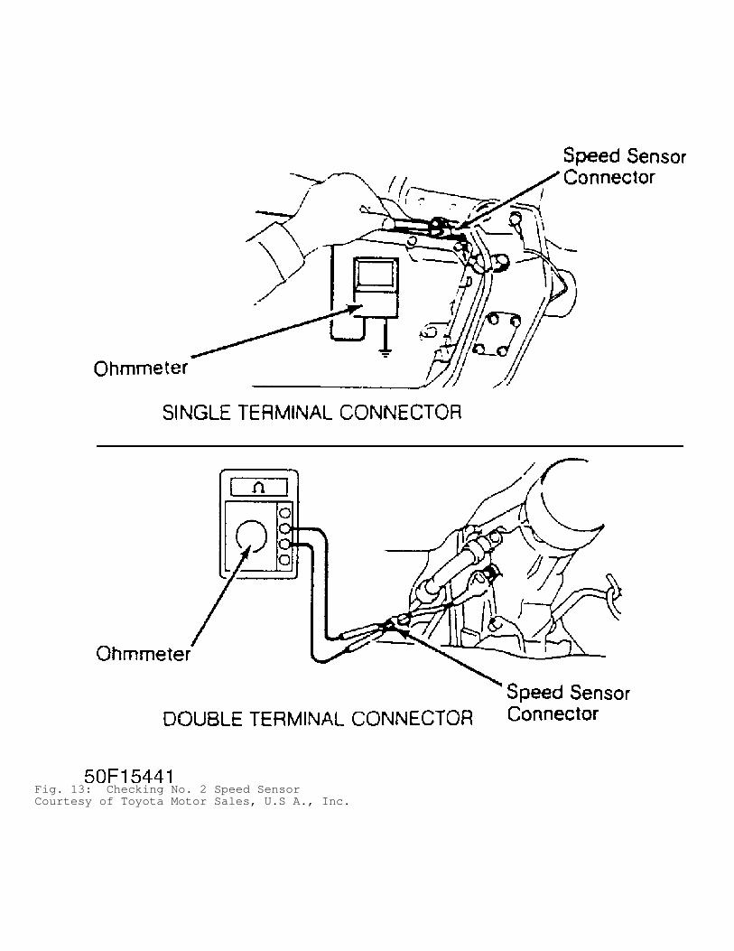
Fig. 13: Checking No. 2 Speed SensorCourtesy of Toyota Motor Sales, U.S A., Inc.
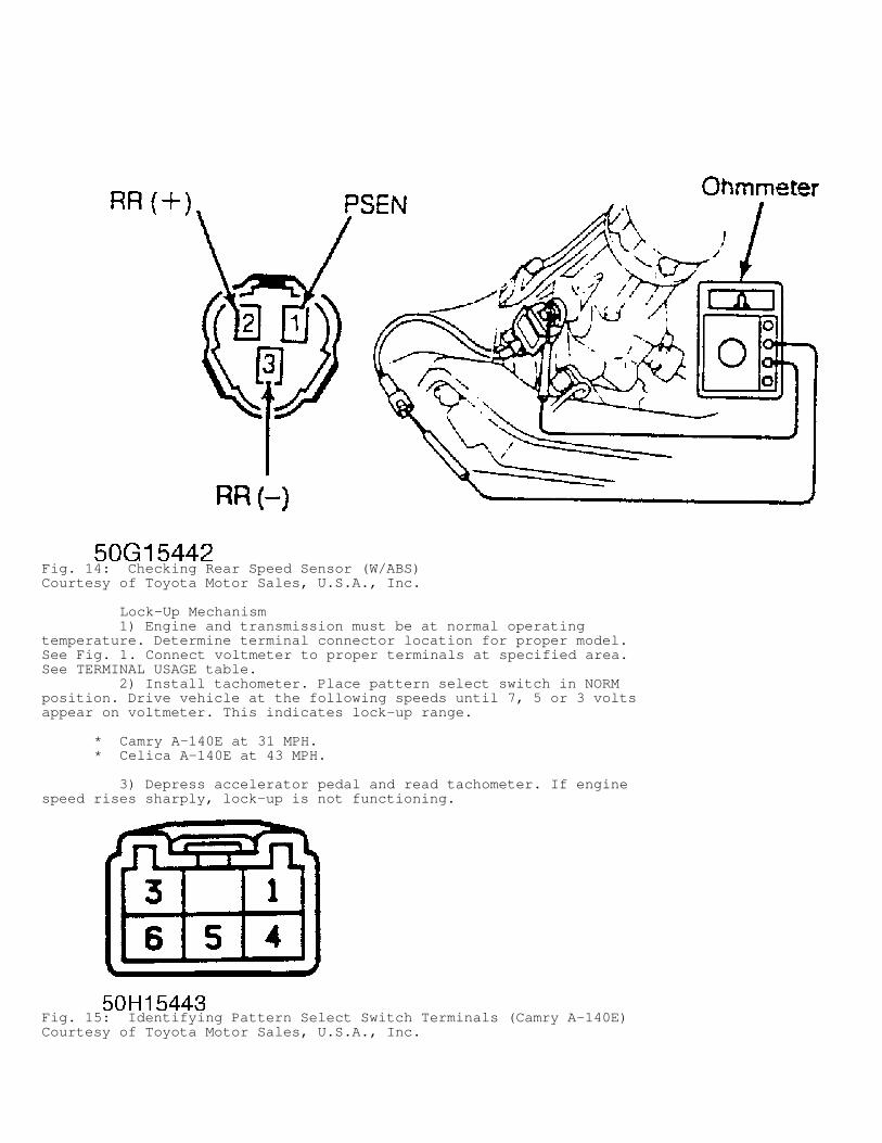
Fig. 14: Checking Rear Speed Sensor (W/ABS)Courtesy of Toyota Motor Sales, U.S.A., Inc.
Lock-Up Mechanism 1) Engine and transmission must be at normal operatingtemperature. Determine terminal connector location for proper model.See Fig. 1. Connect voltmeter to proper terminals at specified area.See TERMINAL USAGE table. 2) Install tachometer. Place pattern select switch in NORMposition. Drive vehicle at the following speeds until 7, 5 or 3 voltsappear on voltmeter. This indicates lock-up range.
* Camry A-140E at 31 MPH. * Celica A-140E at 43 MPH.
3) Depress accelerator pedal and read tachometer. If enginespeed rises sharply, lock-up is not functioning.
Fig. 15: Identifying Pattern Select Switch Terminals (Camry A-140E)Courtesy of Toyota Motor Sales, U.S.A., Inc.
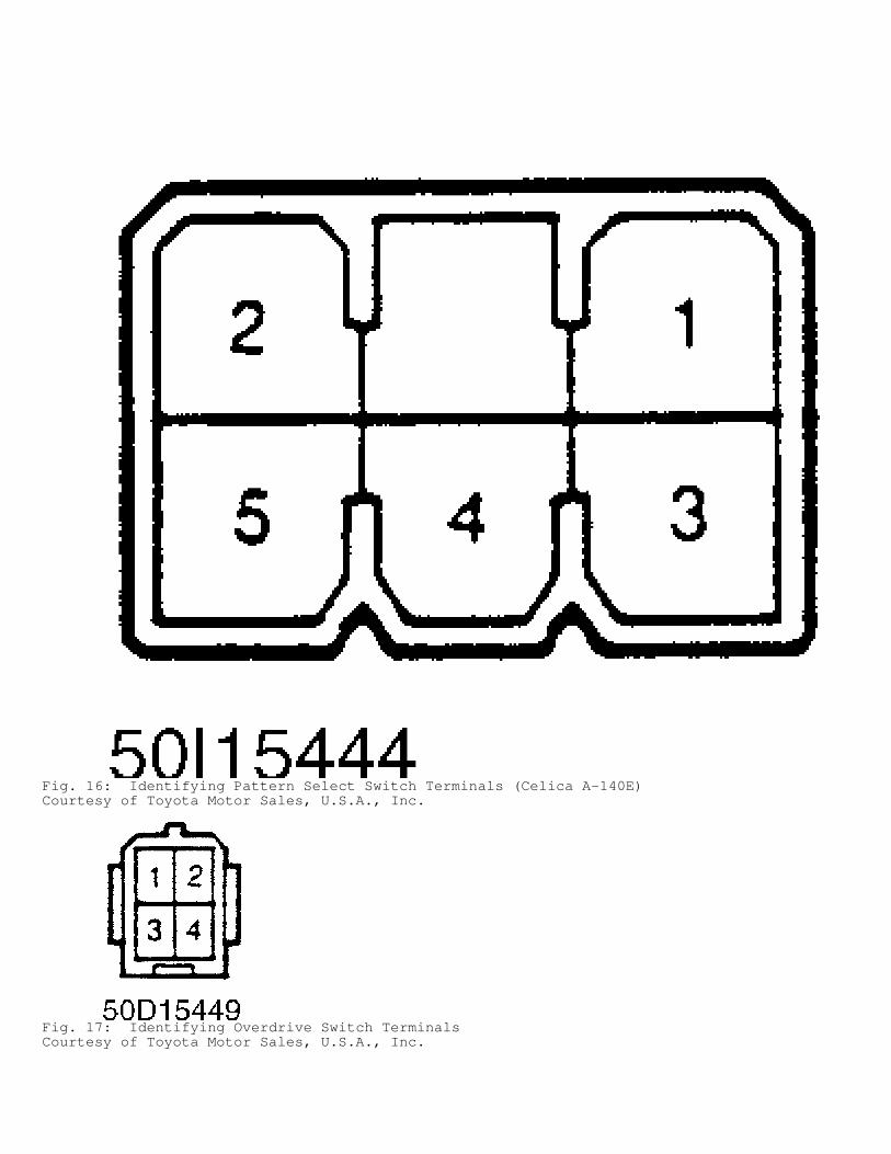
Fig. 16: Identifying Pattern Select Switch Terminals (Celica A-140E)Courtesy of Toyota Motor Sales, U.S.A., Inc.
Fig. 17: Identifying Overdrive Switch TerminalsCourtesy of Toyota Motor Sales, U.S.A., Inc.
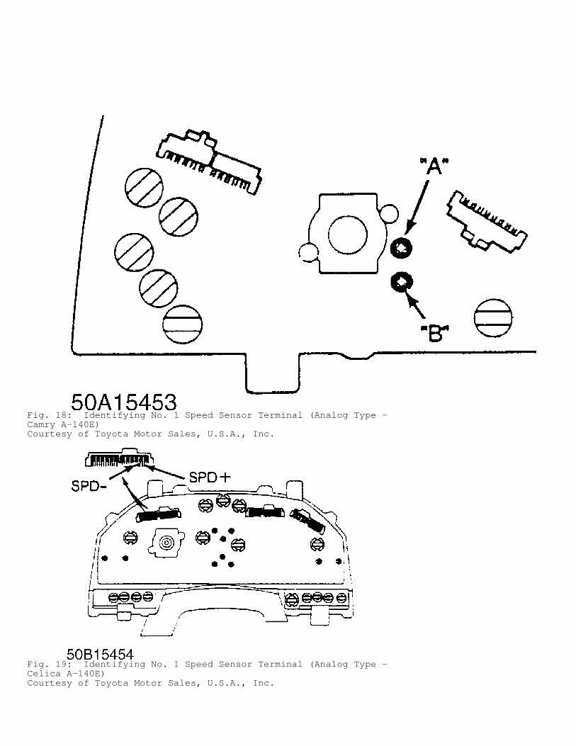
Fig. 18: Identifying No. 1 Speed Sensor Terminal (Analog Type -Camry A-140E)Courtesy of Toyota Motor Sales, U.S.A., Inc.
Fig. 19: Identifying No. 1 Speed Sensor Terminal (Analog Type -Celica A-140E)Courtesy of Toyota Motor Sales, U.S.A., Inc.
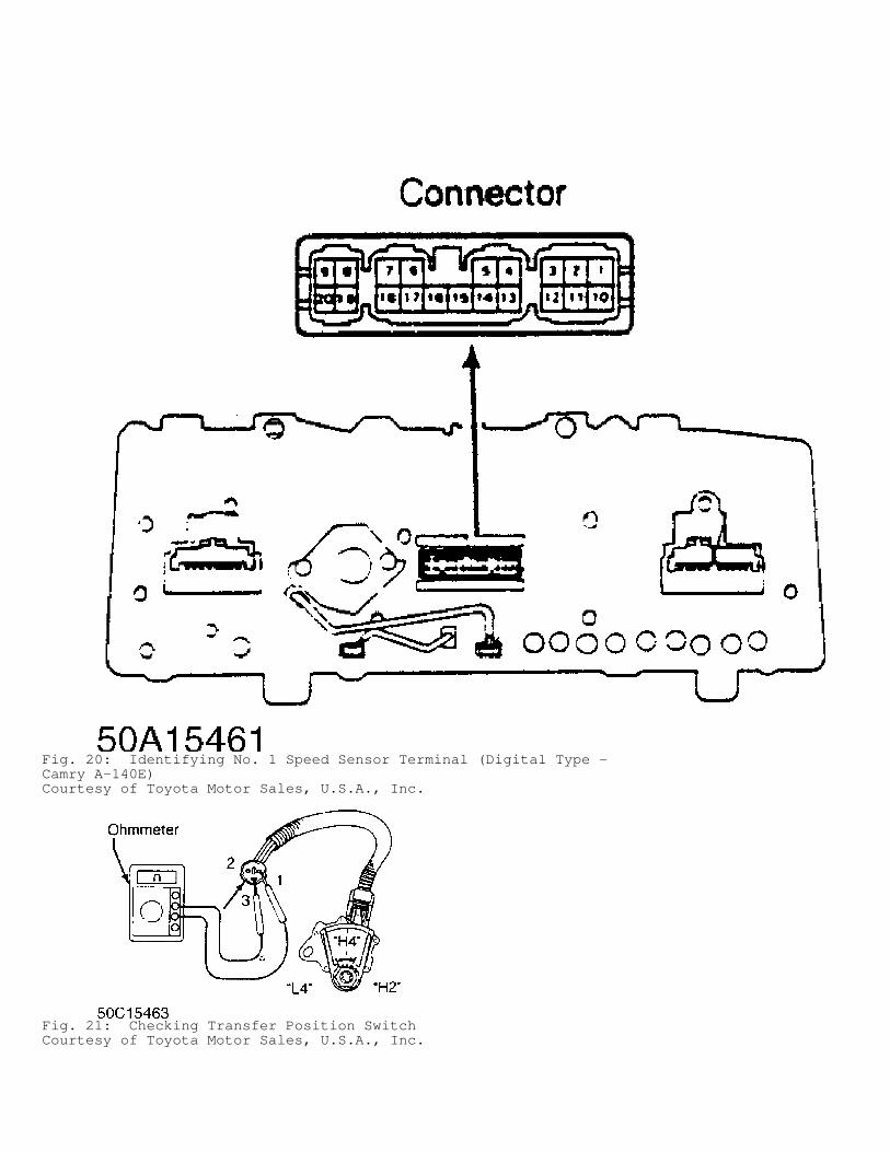
Fig. 20: Identifying No. 1 Speed Sensor Terminal (Digital Type -Camry A-140E)Courtesy of Toyota Motor Sales, U.S.A., Inc.
Fig. 21: Checking Transfer Position SwitchCourtesy of Toyota Motor Sales, U.S.A., Inc.
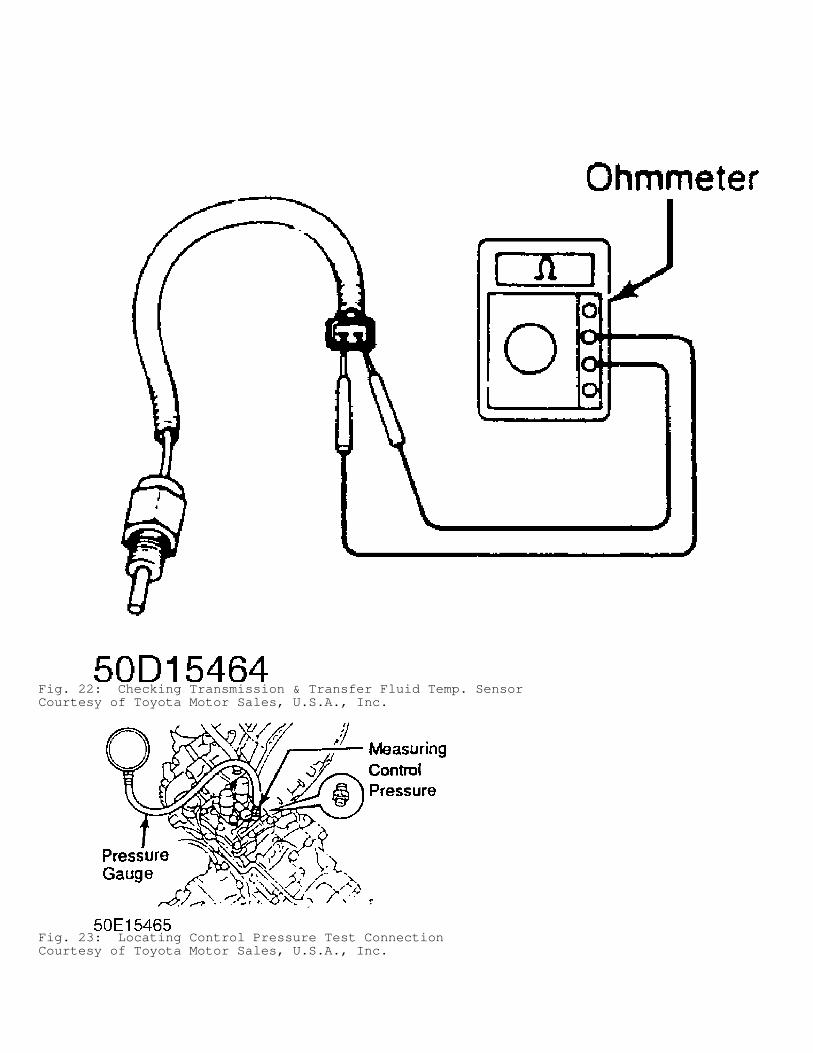
Fig. 22: Checking Transmission & Transfer Fluid Temp. SensorCourtesy of Toyota Motor Sales, U.S.A., Inc.
Fig. 23: Locating Control Pressure Test ConnectionCourtesy of Toyota Motor Sales, U.S.A., Inc.
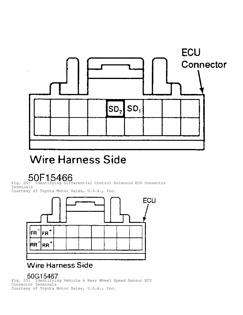
Fig. 24: Identifying Differential Control Solenoid ECU ConnectorTerminalsCourtesy of Toyota Motor Sales, U.S.A., Inc.
Fig. 25: Identifying Vehicle & Rear Wheel Speed Sensor ECUConnector TerminalsCourtesy of Toyota Motor Sales, U.S.A., Inc.
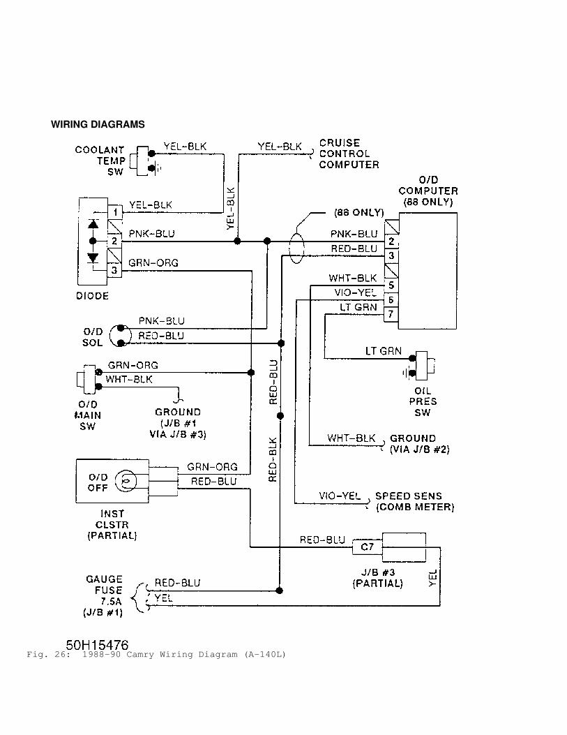
WIRING DIAGRAMS
Fig. 26: 1988-90 Camry Wiring Diagram (A-140L)
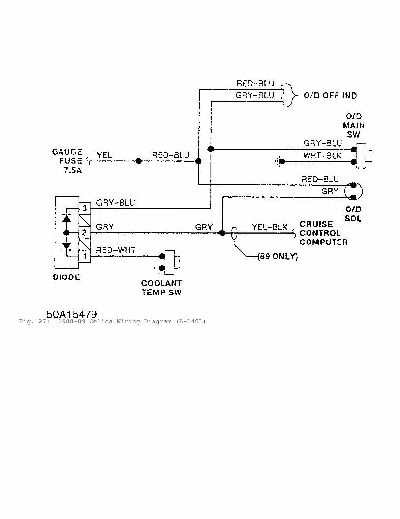
Fig. 27: 1988-89 Celica Wiring Diagram (A-140L)
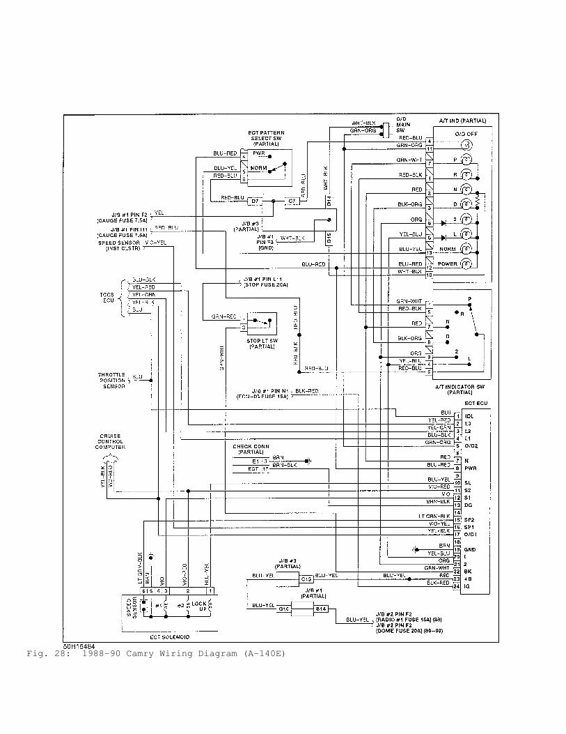
Fig. 28: 1988-90 Camry Wiring Diagram (A-140E)
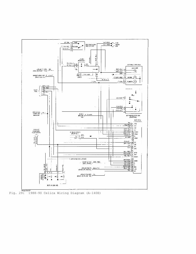
Fig. 29: 1988-90 Celica Wiring Diagram (A-140E)