![Trans -[PtIV(N (OH) (py)(NH )]: A Light-Activated ...mct.aacrjournals.org/content/molcanther/11/9/1894.full.pdf · Trans ,trans,trans-[PtIV(N ... A Light-Activated Antitumor Platinum](https://static.fdocuments.us/doc/165x107/5af8c07c7f8b9ae92b8b7a83/trans-ptivn-oh-pynh-a-light-activated-mct-transtrans-ptivn-.jpg)
AUTO TRANS DIAGNOSIS - A-241E & A-244E Article … Mk1 1985 on Repair Manuals/General/88...AUTO...
35
AUTO TRANS DIAGNOSIS - A-241E & A-244E Article Text 1988 Toyota MR2 For Rse 555 Main Street Clarksville Va 22901 Copyright © 1997 Mitchell International Thursday, February 14, 2002 03:44PM ARTICLE BEGINNING AUTOMATIC TRANSMISSIONS Toyota A-241E & A-244E Electronic Controls APPLICATION APPLICATION ÄÄÄÄÄÄÄÄÄÄÄÄÄÄÄÄÄÄÄÄÄÄÄÄÄÄÄÄÄÄÄÄÄÄÄÄÄÄÄÄÄÄÄÄÄÄÄÄÄÄÄÄÄÄÄÄÄÄÄÄ Vehicle Transmission Model 1988-92 MR2 ....................................... A-241E 1990-92 Celica 2.2L (5S-FE) ....................... A-241E 1992 Paseo ........................................ A-244E ÄÄÄÄÄÄÄÄÄÄÄÄÄÄÄÄÄÄÄÄÄÄÄÄÄÄÄÄÄÄÄÄÄÄÄÄÄÄÄÄÄÄÄÄÄÄÄÄÄÄÄÄÄÄÄÄÄÄÄÄ CAUTION: Celica and MR2 models are equipped with a Supplemental Restraint System (SRS). When servicing vehicle, use care to avoid accidental air bag deployment. All SRS electrical connections and wiring harness(s) are covered with Yellow insulation. SRS-related components are located in steering column, center console, instrument panel and lower panel on instrument panel. DO NOT use electrical test equipment on these circuits. It may be necessary to deactivate SRS before servicing components. See appropriate AIR BAG article in the ACCESSORIES/SAFETY EQUIP section. See the following menu: * 1991 Celica 2.2L & MR2: AIR BAG RESTRAINT SYSTEM * 1992 Celica 2.2L & MR2: AIR BAG RESTRAINT SYSTEM DESCRIPTION Automatic transmission is electronically controlled. Transmission shifting and torque converter lock-up are controlled by an Engine and Electronic Controlled Transmission (ECT) Electronic Control Unit (ECU). NOTE: The Engine and Electronic Controlled Transmission (ECT) Electronic Control Unit (ECU) is used to control the engine fuel injection system and the transmission. In this article, control unit will be referred to as the ECU. The ECU receives information from various input devices and uses this information to control No. 1 and No. 2 solenoids for transmission shifting, and lock-up solenoid for torque converter lock- up. On Celica models, a pattern select switch is located near
Transcript of AUTO TRANS DIAGNOSIS - A-241E & A-244E Article … Mk1 1985 on Repair Manuals/General/88...AUTO...
AUTO TRANS DIAGNOSIS - A-241E & A-244EArticle Text
1988 Toyota MR2For Rse 555 Main Street Clarksville Va 22901
Copyright © 1997 Mitchell InternationalThursday, February 14, 2002 03:44PM
ARTICLE BEGINNING
AUTOMATIC TRANSMISSIONS Toyota A-241E & A-244E Electronic Controls
APPLICATION
APPLICATIONÄÄÄÄÄÄÄÄÄÄÄÄÄÄÄÄÄÄÄÄÄÄÄÄÄÄÄÄÄÄÄÄÄÄÄÄÄÄÄÄÄÄÄÄÄÄÄÄÄÄÄÄÄÄÄÄÄÄÄÄVehicle Transmission Model
1988-92 MR2 ....................................... A-241E1990-92 Celica 2.2L (5S-FE) ....................... A-241E1992 Paseo ........................................ A-244EÄÄÄÄÄÄÄÄÄÄÄÄÄÄÄÄÄÄÄÄÄÄÄÄÄÄÄÄÄÄÄÄÄÄÄÄÄÄÄÄÄÄÄÄÄÄÄÄÄÄÄÄÄÄÄÄÄÄÄÄ
CAUTION: Celica and MR2 models are equipped with a Supplemental Restraint System (SRS). When servicing vehicle, use care to avoid accidental air bag deployment. All SRS electrical connections and wiring harness(s) are covered with Yellow insulation. SRS-related components are located in steering column, center console, instrument panel and lower panel on instrument panel. DO NOT use electrical test equipment on these circuits. It may be necessary to deactivate SRS before servicing components. See appropriate AIR BAG article in the ACCESSORIES/SAFETY EQUIP section. See the following menu:
* 1991 Celica 2.2L & MR2: AIR BAG RESTRAINT SYSTEM * 1992 Celica 2.2L & MR2: AIR BAG RESTRAINT SYSTEM
DESCRIPTION
Automatic transmission is electronically controlled.Transmission shifting and torque converter lock-up are controlled byan Engine and Electronic Controlled Transmission (ECT) ElectronicControl Unit (ECU).
NOTE: The Engine and Electronic Controlled Transmission (ECT) Electronic Control Unit (ECU) is used to control the engine fuel injection system and the transmission. In this article, control unit will be referred to as the ECU.
The ECU receives information from various input devices anduses this information to control No. 1 and No. 2 solenoids fortransmission shifting, and lock-up solenoid for torque converter lock-up. On Celica models, a pattern select switch is located near

AUTO TRANS DIAGNOSIS - A-241E & A-244E
shift lever. See Fig. 1. Pattern select switch contains a POWER(depressed) and a NORMAL (released) operating position. When patternselect switch is depressed, transmission upshifts and downshifts willoccur at a higher vehicle speed than with switch released. An ECTindicator light on instrument panel will come on when switch is inPOWER position. On all models, an Overdrive (OD) switch is mounted on theshift lever. See Fig. 1. When OD switch is depressed to ON position,transmission will shift into 4th gear when shift lever is in "D"position, and OD OFF light on instrument panel will go off. When ODswitch is released to OFF position, transmission will shift into 3rdgear, and OD OFF light on instrument panel will come on. See Fig. 1. Transmission is equipped with a shift lock and key locksystem. Shift lock system prevents shift lever from being moved fromPark unless brake pedal is depressed. In case of a malfunction, shiftlever can be released by depressing shift lock override button,located near shift lever. Key lock system prevents ignition key frombeing moved from ACC to LOCK position unless shift lever is in Park.For more information on shift lock and key lock system, Refer to the SHIFT LOCK SYSTEM article.
OPERATION
ELECTRONIC CONTROL UNIT (ECU)
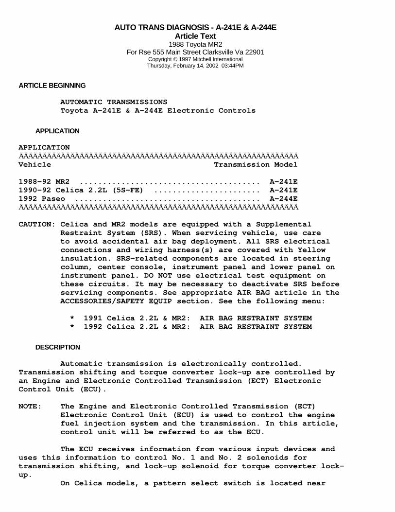
The ECU receives information from various input devices anduses this information to control No. 1, No. 2 and lock-up solenoids.The ECU contains a self-diagnostic system, which will store fault codeif failure or problem exists in the electronic control system. Faultcode can be retrieved to determine transmission problem area. SeeSELF-DIAGNOSTIC SYSTEM. On MR2 models, ECU is located near left rearcorner of engine compartment. See Fig. 1. On Celica and Paseo, ECU islocated near front of center console. See Fig. 1.
ECU INPUT DEVICES
Pattern Select Switch Signal (Celica) Pattern select switch delivers an input signal to ECU toindicate transmission shift points selected by operator. Patternselect switch is located near shift lever. See Fig. 1.
Engine Speed Signal Distributor delivers an engine RPM and crankshaft anglesignal to the ECU.
Neutral Start Switch Signal Neutral start switch delivers an input signal to ECU to

AUTO TRANS DIAGNOSIS - A-241E & A-244E
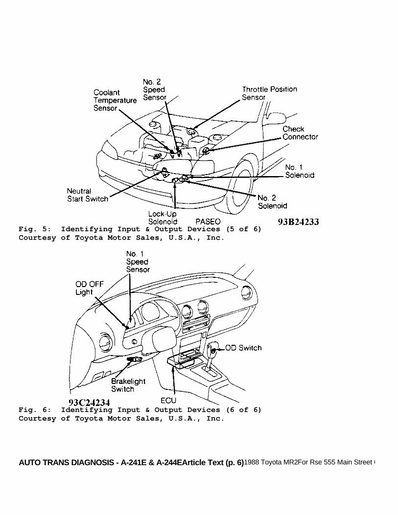
indicate shift lever position. Neutral start switch is located on sideof transmission. See Fig. 1.
Throttle Position Sensor Signal Throttle position sensor delivers an input signal to ECU toindicate throttle position and idle signal. Throttle position sensoris located on side of throttle body. See Fig. 1.
Vehicle Speed Signal Vehicle speed signal is delivered to ECU by speed sensors.Speed sensors are located on transmission and on rear of instrumentpanel. See Fig. 1.
Brakelight Switch Signal Brakelight switch delivers input signal to ECU, indicatingvehicle braking. Brakelight switch is located on brake pedal support.
OD Switch Signal The OD switch provides an input signal to ECU to indicatewhen overdrive is selected by the operator. When OD switch isdepressed to ON position, transmission will shift into 4th gear whenshift lever is in "D" position, and OD OFF light on instrument panelwill go off. When OD switch is released to OFF position, transmissionwill shift into 3rd gear, and OD OFF light on instrument panel willcome on. See Fig. 1. The OD switch is mounted on the shift lever. SeeFig. 1.
Coolant Temperature Sensor Signal Coolant temperature sensor delivers input signal to ECU,indicating engine coolant temperature. Coolant temperature sensor islocated in coolant passage on the engine. See Fig. 1.
Cruise Control Electronic Control Unit (ECU) Cruise control ECU delivers an input signal to controloverdrive operation in accordance with vehicle speed when cruisecontrol is operating. When in overdrive with cruise control on, ifvehicle speed drops 3 MPH below the set speed, overdrive is released.Once vehicle speed is above the set speed, overdrive is resumed. OnMR2, cruise control ECU is located behind passenger's side ofinstrument panel. On Celica and Paseo, cruise control ECU is locatednear front of center console. See Fig. 7.

AUTO TRANS DIAGNOSIS - A-241E & A-244EArticle Text (p. 4)1988 Toyota MR2For Rse 555 Main Street Clarksville Va 22901
Fig. 1: Identifying Input & Output Devices (1 of 6)Courtesy of Toyota Motor Sales, U.S.A., Inc.
Fig. 2: Identifying Input & Output Devices (2 of 6)Courtesy of Toyota Motor Sales, U.S.A., Inc.
AUTO TRANS DIAGNOSIS - A-241E & A-244EArticle Text (p. 5)1988 Toyota MR2For Rse 555 Main Street Clarksville Va 22901
Fig. 3: Identifying Input & Output Devices (3 of 6)Courtesy of Toyota Motor Sales, U.S.A., Inc.
Fig. 4: Identifying Input & Output Devices (4 of 6)Courtesy of Toyota Motor Sales, U.S.A., Inc.
AUTO TRANS DIAGNOSIS - A-241E & A-244EArticle Text (p. 6)1988 Toyota MR2For Rse 555 Main Street Clarksville Va 22901
Fig. 5: Identifying Input & Output Devices (5 of 6)Courtesy of Toyota Motor Sales, U.S.A., Inc.
Fig. 6: Identifying Input & Output Devices (6 of 6)Courtesy of Toyota Motor Sales, U.S.A., Inc.

AUTO TRANS DIAGNOSIS - A-241E & A-244EArticle Text (p. 7)1988 Toyota MR2For Rse 555 Main Street Clarksville Va 22901
Fig. 7: Identifying Cruise Control ECU (1 of 2)Courtesy of Toyota Motor Sales, U.S.A., Inc.
Fig. 8: Identifying Cruise Control ECU (1 of 2)Courtesy of Toyota Motor Sales, U.S.A., Inc.
ECU OUTPUT DEVICES
No. 1 & No. 2 Solenoids The ECU controls transmission shifting by delivering anoutput signal to operate proper solenoid. Solenoids are operated inaccordance with shift lever range. See Fig. 9. If a solenoidmalfunctions, designated gear may result. See Fig. 9. Solenoids arelocated on transmission. See Fig. 1.
Lock-Up Solenoid ECU controls torque converter lock-up by delivering an outputsignal to lock-up solenoid. Lock-up solenoid is activated when shiftlever is in "D" position and vehicle is at specified speed. Lock-upsolenoid is located on transmission. See Fig. 1.

AUTO TRANS DIAGNOSIS - A-241E & A-244EArticle Text (p. 8)1988 Toyota MR2For Rse 555 Main Street Clarksville Va 22901
Fig. 9: Determining No. 1 & No. 2 Solenoid OperationCourtesy of Toyota Motor Sales, U.S.A., Inc.
SELF-DIAGNOSTIC SYSTEM
SYSTEM DIAGNOSIS
ECU monitors transmission operation and contains a self-diagnostic system which stores fault code if transmission electroniccontrol system failure or problem exists. If a problem exists in theNo. 1 or No. 2 solenoids or speed sensors and fault code is set, theECU delivers a signal to blink the OD OFF light on instrument panel towarn the driver.
NOTE: The OD OFF light on instrument panel will not blink to warn the driver if a problem exists or fault code is stored for lock-up solenoid, or problem exists with brakelight switch signal or throttle position sensor signal.
Fault codes may be set if a failure exists and can beretrieved for transmission diagnosis. See TRANSMISSION TESTING.
TRANSMISSION TESTING
NOTE: Before testing transmission, ensure fluid level is correct and throttle and shift cables are properly adjusted. Ensure engine starts with shift lever in Park and Neutral to ensure proper adjustment of neutral start switch. Transmission must first be tested by checking for stored fault codes. See RETRIEVING FAULT CODES.

AUTO TRANS DIAGNOSIS - A-241E & A-244EArticle Text (p. 9)
RETRIEVING FAULT CODES
NOTE: Before retrieving fault codes, ensure proper battery voltage exists for proper self-diagnosis system operation. Perform diagnostic circuit check before retrieving fault codes to ensure proper operation of OD OFF light. See DIAGNOSTIC CIRCUIT CHECK heading below.
Diagnostic Circuit Check 1) Turn ignition on. Release OD switch on shift lever to OFFposition. Ensure OD OFF light on instrument panel comes on. If OD OFFlight does not come on, check OD switch and wiring circuit.
2) Depress OD switch to ON position. Ensure OD OFF light oninstrument panel goes off. If OD OFF light remains on, check OD switchand wiring circuit. If OD OFF light is blinking, check for storedfault codes. See ECU FAULT CODES heading below.
ECU Fault Codes 1) Turn ignition on. DO NOT start engine. Depress OD switchon shift lever to the ON position.
NOTE: Fault codes can only be retrieved with OD switch in ON position. If OD switch is in OFF position, OD OFF light will be on continuously and will not blink the fault code.
2) Locate check connector in engine compartment. See Fig. 1.Note check connector terminal identification. See Fig. 10. Installjumper wire between designated terminals of check connector. See CHECKCONNECTOR TERMINAL USAGE table.
CHECK CONNECTOR TERMINAL USAGEÄÄÄÄÄÄÄÄÄÄÄÄÄÄÄÄÄÄÄÄÄÄÄÄÄÄÄÄÄÄÄÄÄÄÄÄÄÄÄÄÄÄÄÄÄÄÄÄÄÄApplication Terminal Usage
Celica 1991 Models .......................... TT & E1 1992 Models ......................... TE1 & E1MR2 1991 Models .......................... TT & E1 1992 Models ......................... TE1 & E1Paseo .................................. TT & E1ÄÄÄÄÄÄÄÄÄÄÄÄÄÄÄÄÄÄÄÄÄÄÄÄÄÄÄÄÄÄÄÄÄÄÄÄÄÄÄÄÄÄÄÄÄÄÄÄÄÄ
3) Note number of blinks from OD OFF light on instrumentpanel. If normal system operation exists, OD OFF light will blink onceevery .25 second. See Fig. 11.

AUTO TRANS DIAGNOSIS - A-241E & A-244EArticle Text (p. 10)
4) If system is operating correctly and no fault code exists,turn ignition off and remove jumper wire. Perform MANUAL SHIFTING TESTunder TRANSMISSION SHIFT TESTING to determine if problem is aelectrical or mechanical transmission problem. Check system bysymptom. See appropriate symptom under SYMPTOM TROUBLESHOOTING. 5) If fault code exists, OD OFF light will blink once every .5 second. The number of blinks will equal the first digit of faultcode. After a pause of 1.5 seconds, the second digit will bedisplayed. See Fig. 11. 6) If more than one fault code exists, the next fault codewill be displayed after pause of 2.5 second. See Fig. 11. System willdisplay smallest value fault code first and then continue to largestvalue fault code. Fault codes will be repeated. 7) Once fault code is obtained, determine probable cause andsymptom. See FAULT CODE IDENTIFICATION table. For trouble shooting offault codes, see FAULT CODE TROUBLESHOOTING. Turn ignition off andremove jumper wire.
NOTE: Once repairs have been performed, fault codes must be cleared from ECU memory. See CLEARING FAULT CODES under TRANSMISSION TESTING.
FAULT CODE IDENTIFICATIONÄÄÄÄÄÄÄÄÄÄÄÄÄÄÄÄÄÄÄÄÄÄÄÄÄÄÄÄÄÄÄÄÄÄÄÄÄÄÄÄÄÄÄÄÄÄÄÄÄÄÄÄÄÄÄÄÄÄÄÄFault Code (1) Probable Cause
42 ...................... (2) Defective No. 1 Speed Sensor61 ...................... (2) Defective No. 2 Speed Sensor62 .............................. Defective No. 1 Solenoid63 .............................. Defective No. 2 Solenoid64 ............................ Defective Lock-Up Solenoid
(1) - Check listed component for probable cause. Also check wiring and connections of specified component.(2) - If both the No. 1 and the No. 2 speed sensors fail simultaneously, the fault code will not exist, but transmission will not upshift from 1st gear with shift lever in "D" position.ÄÄÄÄÄÄÄÄÄÄÄÄÄÄÄÄÄÄÄÄÄÄÄÄÄÄÄÄÄÄÄÄÄÄÄÄÄÄÄÄÄÄÄÄÄÄÄÄÄÄÄÄÄÄÄÄÄÄÄÄ
Fig. 10: Identifying Check Connector TerminalsCourtesy of Toyota Motor Sales, U.S.A., Inc.

AUTO TRANS DIAGNOSIS - A-241E & A-244EArticle Text (p. 11)1988 Toyota MR2For Rse 555 Main Street Clarksville Va 22901
Fig. 11: Identifying Fault Code Displays (Normal System Operation)Courtesy of Toyota Motor Sales, U.S.A., Inc.
Fig. 12: Identifying Fault Code Displays (System With Fault Codes)Courtesy of Toyota Motor Sales, U.S.A., Inc.
CLEARING FAULT CODES
1) Once repairs have been performed, fault codes must becleared from ECU memory. Remove EFI fuse (15-amp) from enginecompartment fuse box for 10 seconds to clear memory in ECU. 2) On MR2, engine compartment fuse box is located on driver'sside of engine compartment. On Celica and Paseo, engine compartmentfuse box is located near the battery in engine compartment. 3) Fuse may need to be removed for more than 10 seconds incold ambient temperatures. Reinstall fuse.
NOTE: Fault codes may also be cleared by disconnecting negative battery cable, but memory for electronic components will be also be canceled.
FAULT CODE TROUBLESHOOTING
When trouble shooting transmission, first check for storedfault codes and repair as necessary. If no fault codes exist, performmanual shifting test to determine if problem area is in the electricalcircuits or if there is a mechanical transmission problem. Refer toMANUAL SHIFTING TEST under TRANSMISSION SHIFT TESTING.
AUTO TRANS DIAGNOSIS - A-241E & A-244E
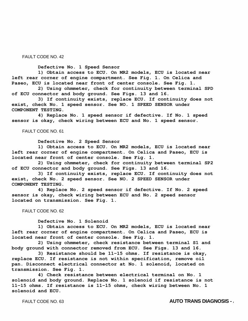
FAULT CODE NO. 42
Defective No. 1 Speed Sensor 1) Obtain access to ECU. On MR2 models, ECU is located nearleft rear corner of engine compartment. See Fig. 1. On Celica andPaseo, ECU is located near front of center console. See Fig. 1. 2) Using ohmmeter, check for continuity between terminal SPDof ECU connector and body ground. See Figs. 13 and 16. 3) If continuity exists, replace ECU. If continuity does notexist, check No. 1 speed sensor. See NO. 1 SPEED SENSOR underCOMPONENT TESTING. 4) Replace No. 1 speed sensor if defective. If No. 1 speedsensor is okay, check wiring between ECU and No. 1 speed sensor.
FAULT CODE NO. 61
Defective No. 2 Speed Sensor 1) Obtain access to ECU. On MR2 models, ECU is located nearleft rear corner of engine compartment. On Celica and Paseo, ECU islocated near front of center console. See Fig. 1. 2) Using ohmmeter, check for continuity between terminal SP2of ECU connector and body ground. See Figs. 13 and 16. 3) If continuity exists, replace ECU. If continuity does notexist, check No. 2 speed sensor. See NO. 2 SPEED SENSOR underCOMPONENT TESTING. 4) Replace No. 2 speed sensor if defective. If No. 2 speedsensor is okay, check wiring between ECU and No. 2 speed sensorlocated on transmission. See Fig. 1.
FAULT CODE NO. 62
Defective No. 1 Solenoid 1) Obtain access to ECU. On MR2 models, ECU is located nearleft rear corner of engine compartment. On Celica and Paseo, ECU islocated near front of center console. See Fig. 1. 2) Using ohmmeter, check resistance between terminal S1 andbody ground with connector removed from ECU. See Figs. 13 and 16. 3) Resistance should be 11-15 ohms. If resistance is okay,replace ECU. If resistance is not within specification, remove oilpan. Disconnect electrical connector at No. 1 solenoid, located ontransmission. See Fig. 1. 4) Check resistance between electrical terminal on No. 1solenoid and body ground. Replace No. 1 solenoid if resistance is not11-15 ohms. If resistance is 11-15 ohms, check wiring between No. 1solenoid and ECU.
FAULT CODE NO. 63

AUTO TRANS DIAGNOSIS - A-241E & A-244EArticle Text (p. 13)1988 Toyota MR2
Defective No. 2 Solenoid 1) Obtain access to ECU. On MR2 models, ECU is located nearleft rear corner of engine compartment. On Celica and Paseo, ECU islocated near front of center console. See Fig. 1. 2) Using ohmmeter, check resistance between terminal S2 andbody ground with connector removed from ECU. See Figs. 13 and 16. 3) Resistance should be 11-15 ohms. If resistance is okay,replace ECU. If resistance is not within specification, remove oilpan. Disconnect electrical connector at No. 2 solenoid, located ontransmission. See Fig. 1. 4) Check resistance between electrical terminal on No. 2solenoid and body ground. Replace No. 2 solenoid if resistance is not11-15 ohms. If resistance is 11-15 ohms, check wiring between No. 2solenoid and ECU.
FAULT CODE NO. 64
Defective Lock-Up Solenoid 1) Obtain access to ECU. On MR2 models, ECU is located nearleft rear corner of engine compartment. On Celica and Paseo, ECU islocated near front of center console. See Fig. 1. 2) Using ohmmeter, check resistance between terminal SL andbody ground with connector removed from ECU. See Figs. 13 and 16. 3) Resistance should be 11-15 ohms. If resistance is okay,replace ECU. If resistance is not within specification, remove oilpan. Disconnect electrical connector at lock-up solenoid. See Fig. 1. 4) Check resistance between electrical terminal on lock-upsolenoid and body ground. Replace lock-up solenoid if resistance isnot 11-15 ohms. If resistance is 11-15 ohms, check wiring betweenlock-up solenoid and ECU.
TRANSMISSION SHIFT TESTING
MANUAL SHIFTING TEST
NOTE: Perform manual shifting test if no fault codes exist. Manual shifting test determines if problem area is in electrical circuits or a mechanical transmission problem.
1) With ignition off, disconnect electrical connector fromsolenoids on transmission. Electrical connector is located nearneutral start switch on transmission. 2) Road test vehicle and ensure transmission gear changescorresponds with shift lever position. See GEAR APPLICATION table. Ifabnormality exists, a mechanical transmission problem exists. 3) If all gears are correct, perform trouble shooting in
AUTO TRANS DIAGNOSIS - A-241E & A-244E
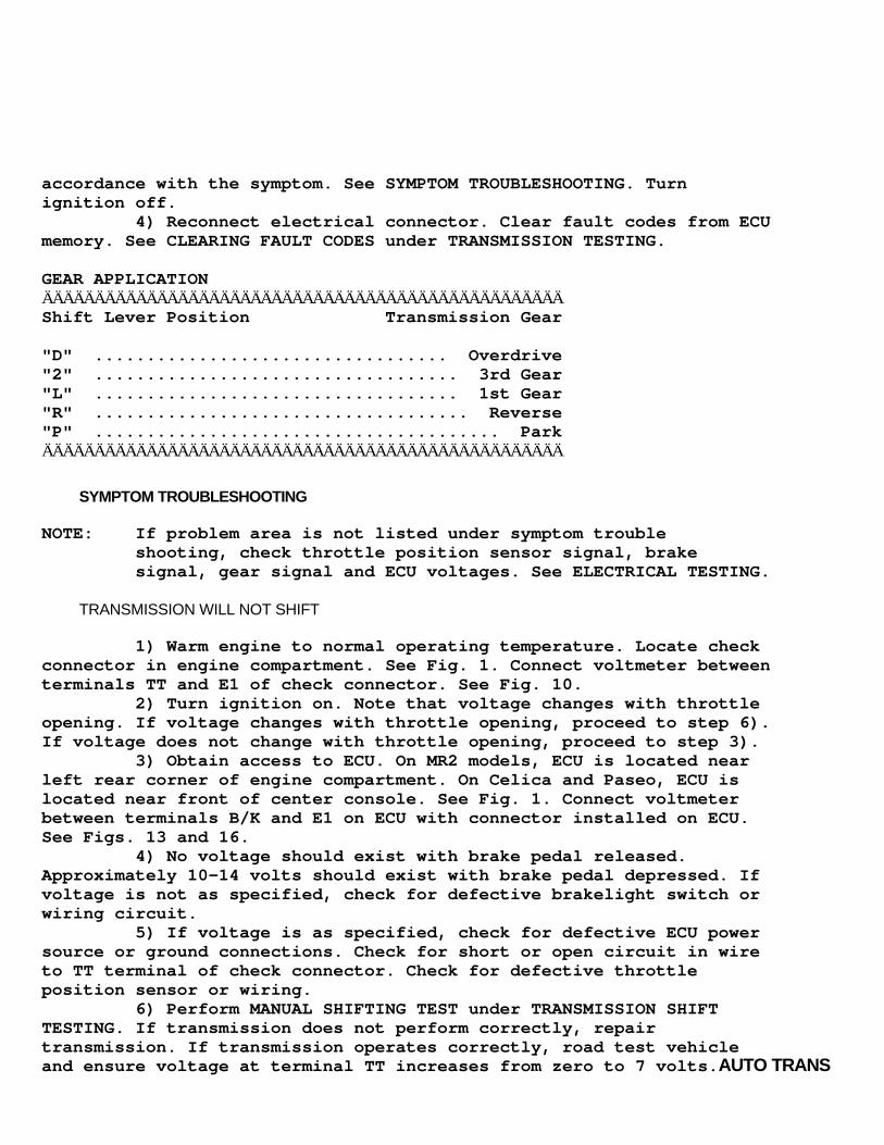
accordance with the symptom. See SYMPTOM TROUBLESHOOTING. Turnignition off. 4) Reconnect electrical connector. Clear fault codes from ECUmemory. See CLEARING FAULT CODES under TRANSMISSION TESTING.
GEAR APPLICATIONÄÄÄÄÄÄÄÄÄÄÄÄÄÄÄÄÄÄÄÄÄÄÄÄÄÄÄÄÄÄÄÄÄÄÄÄÄÄÄÄÄÄÄÄÄÄÄÄÄÄShift Lever Position Transmission Gear
"D" .................................. Overdrive"2" ................................... 3rd Gear"L" ................................... 1st Gear"R" .................................... Reverse"P" ....................................... ParkÄÄÄÄÄÄÄÄÄÄÄÄÄÄÄÄÄÄÄÄÄÄÄÄÄÄÄÄÄÄÄÄÄÄÄÄÄÄÄÄÄÄÄÄÄÄÄÄÄÄ
SYMPTOM TROUBLESHOOTING
NOTE: If problem area is not listed under symptom trouble shooting, check throttle position sensor signal, brake signal, gear signal and ECU voltages. See ELECTRICAL TESTING.
TRANSMISSION WILL NOT SHIFT
1) Warm engine to normal operating temperature. Locate checkconnector in engine compartment. See Fig. 1. Connect voltmeter betweenterminals TT and E1 of check connector. See Fig. 10. 2) Turn ignition on. Note that voltage changes with throttleopening. If voltage changes with throttle opening, proceed to step 6).If voltage does not change with throttle opening, proceed to step 3). 3) Obtain access to ECU. On MR2 models, ECU is located nearleft rear corner of engine compartment. On Celica and Paseo, ECU islocated near front of center console. See Fig. 1. Connect voltmeterbetween terminals B/K and E1 on ECU with connector installed on ECU.See Figs. 13 and 16. 4) No voltage should exist with brake pedal released.Approximately 10-14 volts should exist with brake pedal depressed. Ifvoltage is not as specified, check for defective brakelight switch orwiring circuit. 5) If voltage is as specified, check for defective ECU powersource or ground connections. Check for short or open circuit in wireto TT terminal of check connector. Check for defective throttleposition sensor or wiring. 6) Perform MANUAL SHIFTING TEST under TRANSMISSION SHIFTTESTING. If transmission does not perform correctly, repairtransmission. If transmission operates correctly, road test vehicleand ensure voltage at terminal TT increases from zero to 7 volts.
AUTO TRANS DIAGNOSIS - A-241E & A-244E
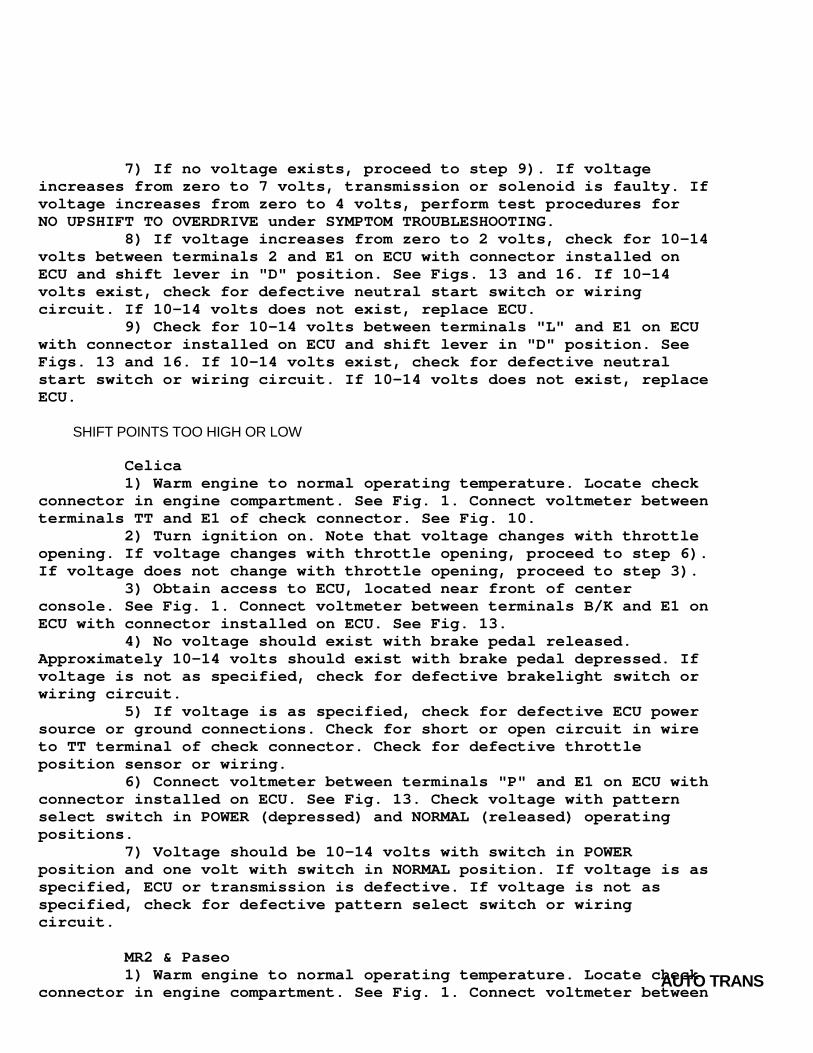
7) If no voltage exists, proceed to step 9). If voltageincreases from zero to 7 volts, transmission or solenoid is faulty. Ifvoltage increases from zero to 4 volts, perform test procedures forNO UPSHIFT TO OVERDRIVE under SYMPTOM TROUBLESHOOTING. 8) If voltage increases from zero to 2 volts, check for 10-14volts between terminals 2 and E1 on ECU with connector installed onECU and shift lever in "D" position. See Figs. 13 and 16. If 10-14volts exist, check for defective neutral start switch or wiringcircuit. If 10-14 volts does not exist, replace ECU. 9) Check for 10-14 volts between terminals "L" and E1 on ECUwith connector installed on ECU and shift lever in "D" position. SeeFigs. 13 and 16. If 10-14 volts exist, check for defective neutralstart switch or wiring circuit. If 10-14 volts does not exist, replaceECU.
SHIFT POINTS TOO HIGH OR LOW
Celica 1) Warm engine to normal operating temperature. Locate checkconnector in engine compartment. See Fig. 1. Connect voltmeter betweenterminals TT and E1 of check connector. See Fig. 10. 2) Turn ignition on. Note that voltage changes with throttleopening. If voltage changes with throttle opening, proceed to step 6).If voltage does not change with throttle opening, proceed to step 3). 3) Obtain access to ECU, located near front of centerconsole. See Fig. 1. Connect voltmeter between terminals B/K and E1 onECU with connector installed on ECU. See Fig. 13. 4) No voltage should exist with brake pedal released.Approximately 10-14 volts should exist with brake pedal depressed. Ifvoltage is not as specified, check for defective brakelight switch orwiring circuit. 5) If voltage is as specified, check for defective ECU powersource or ground connections. Check for short or open circuit in wireto TT terminal of check connector. Check for defective throttleposition sensor or wiring. 6) Connect voltmeter between terminals "P" and E1 on ECU withconnector installed on ECU. See Fig. 13. Check voltage with patternselect switch in POWER (depressed) and NORMAL (released) operatingpositions. 7) Voltage should be 10-14 volts with switch in POWERposition and one volt with switch in NORMAL position. If voltage is asspecified, ECU or transmission is defective. If voltage is not asspecified, check for defective pattern select switch or wiringcircuit.
MR2 & Paseo 1) Warm engine to normal operating temperature. Locate checkconnector in engine compartment. See Fig. 1. Connect voltmeter between

AUTO TRANS DIAGNOSIS - A-241E & A-244E
terminals TT and E1 of check connector. See Fig. 10. 2) Turn ignition on. Note that voltage changes with throttleopening. If voltage changes with throttle opening, ECU or transmissionis defective. If voltage does not change with throttle opening,proceed to next step. 3) Obtain access to ECU. On MR2 models, ECU is located nearleft rear corner of engine compartment. On Paseo, ECU is located nearfront of center console. See Fig. 1. Connect voltmeter betweenterminals B/K and E1 on ECU with connector installed on ECU. SeeFig. 7. 4) No voltage should exist with brake pedal released.Approximately 10-14 volts should exist with brake pedal depressed. Ifvoltage is not as specified, check for defective brakelight switch orwiring circuit.
5) If voltage is as specified, check for defective ECU powersource or ground connections. Check for short or open circuit in wireto TT terminal of check connector. Check for defective throttleposition sensor or wiring.
NO UPSHIFT TO OVERDRIVE
1) Warm engine to normal operating temperature. With ignitionoff, disconnect electrical connector from solenoids on transmission.Electrical connector is located near neutral start switch ontransmission. 2) Road test vehicle and note if transmission upshifts tooverdrive once transmission shifts from "L" to "2" and then into "D"range. Reconnect electrical connector. Clear fault codes from ECUmemory, as disconnecting electrical connector may set fault code. SeeCLEARING FAULT CODES under TRANSMISSION TESTING. If no overdriveupshift exists, transmission is defective. If overdrive upshiftexists, proceed to step 3). 3) Locate check connector in engine compartment. See Fig. 1.Connect voltmeter between terminals TT and E1 of check connector. SeeFig. 10. Road test vehicle and ensure voltage at terminal TT increasesfrom zero to 7 volts. 4) If no voltage exists, obtain access to ECU. On MR2 models,ECU is located near left rear corner of engine compartment. On Celicaand Paseo, ECU is located near front of center console. See Fig. 1. 5) Check for 10-14 volts between terminals "L" and E1 on ECUwith connector installed on ECU with shift lever in "D" position andignition on. See Figs. 14 and 16. If 10-14 volts exist, check fordefective neutral start switch or wiring circuit. If 10-14 volts doesnot exist, replace ECU. 6) If voltage increases from zero to 2 volts, check for 10-14volts between terminals 2 and E1 on ECU with connector installed onECU with shift lever in "D" position and ignition on. See Figs. 13 and
AUTO TRANS DIAGNOSIS - A-241E & A-244E
13. If 10-14 volts exist, check for defective neutral start switch orwiring circuit. If 10-14 volts does not exist, replace ECU. 7) If voltage increases from zero to 7 volts, transmission orsolenoid is faulty. If voltage increases from zero to 4 volts, connectvoltmeter between terminals OD2 and E1 on ECU with connector installedon ECU. See Figs. 13 and 16. 8) Turn ignition on. Check voltage with OD switch on theshift lever in released (OFF position) and depressed (ON position). Novoltage should exist with switch released and 10-14 volts should existwith switch depressed. 9) If voltage is correct, proceed to step 10). If voltage isnot as specified, check for defective OD switch or wiring circuit. 10) Check voltage between terminals OD1 and E1 on ECU withconnector installed on ECU and ignition on. Voltage should be about 5volts. If voltage is correct, replace ECU. If voltage is not correct,proceed to step 11). 11) Disconnect electrical connector from cruise controlElectronic Control Unit (ECU). On MR2, cruise control ECU is locatedbehind passenger's side of instrument panel. On Celica and Paseo,cruise control ECU is located near front of center console. SeeFig. 2. 12) Check voltage between terminals OD1 and E1 on ECU withconnector installed on ECU and ignition on. If voltage is now about 5volts, replace cruise control ECU. If voltage is not about 5 volts,check for defective cruise control ECU wiring. If wiring is okay,replace ECU.
NO LOCK-UP
1) Warm engine to normal operating temperature. Locate checkconnector in engine compartment. See Fig. 1. Connect voltmeter betweenterminals TT and E1 of check connector. See Fig. 10. 2) Road test vehicle and ensure voltage at terminal TT is 7volts in lock-up range. If voltage is correct, lock-up solenoid,torque converter or transmission is defective. 3) If voltage is not as specified, obtain access to ECU. OnMR2 models, ECU is located near left rear corner of enginecompartment. See Fig. 1. On Celica and Paseo, ECU is located nearfront of center console. See Fig. 1. 4) Connect voltmeter between terminals B/K and E1 on ECU withconnector installed on ECU. See Figs. 13 and 16. 5) No voltage should exist with brake pedal released.Approximately 10-14 volts should exist with brake pedal depressed. Ifvoltage is not as specified, check for defective brakelight switch orwiring circuit. 6) If voltage is as specified, check for defective ECU powersource or ground connections. Check for defective throttle positionsensor or wiring.
AUTO TRANS DIAGNOSIS - A-241E & A-244EArticle Text (p. 18)1988 Toyota MR2
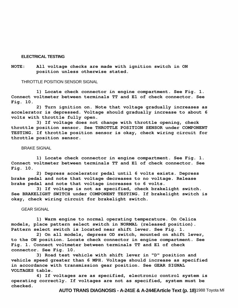
ELECTRICAL TESTING
NOTE: All voltage checks are made with ignition switch in ON position unless otherwise stated.
THROTTLE POSITION SENSOR SIGNAL
1) Locate check connector in engine compartment. See Fig. 1.Connect voltmeter between terminals TT and E1 of check connector. SeeFig. 10. 2) Turn ignition on. Note that voltage gradually increases asaccelerator is depressed. Voltage should gradually increase to about 6volts with throttle fully open. 3) If voltage does not change with throttle opening, checkthrottle position sensor. See THROTTLE POSITION SENSOR under COMPONENTTESTING. If throttle position sensor is okay, check wiring circuit forthrottle position sensor.
BRAKE SIGNAL
1) Locate check connector in engine compartment. See Fig. 1.Connect voltmeter between terminals TT and E1 of check connector. SeeFig. 10. 2) Depress accelerator pedal until 6 volts exists. Depressbrake pedal and note that voltage decreases to no voltage. Releasebrake pedal and note that voltage increases to 6 volts. 3) If voltage is not as specified, check brakelight switch.See BRAKELIGHT SWITCH under COMPONENT TESTING. If brakelight switch isokay, check wiring circuit for brakelight switch.
GEAR SIGNAL
1) Warm engine to normal operating temperature. On Celicamodels, place pattern select switch in NORMAL (released position).Pattern select switch is located near shift lever. See Fig. 1. 2) On all models, depress OD switch, mounted on shift lever,to the ON position. Locate check connector in engine compartment. SeeFig. 1. Connect voltmeter between terminals TT and E1 of checkconnector. See Fig. 10. 3) Road test vehicle with shift lever in "D" position andvehicle speed greater than 6 MPH. Voltage should increase as specifiedin accordance with transmission gear position. See GEAR SIGNALVOLTAGES table. 4) If voltages are as specified, electronic control system isoperating correctly. If voltages are not as specified, system must bechecked.
AUTO TRANS DIAGNOSIS - A-241E & A-244EArticle Text (p. 19)1988 Toyota MR2For Rse 555 Main Street Clarksville Va 22901
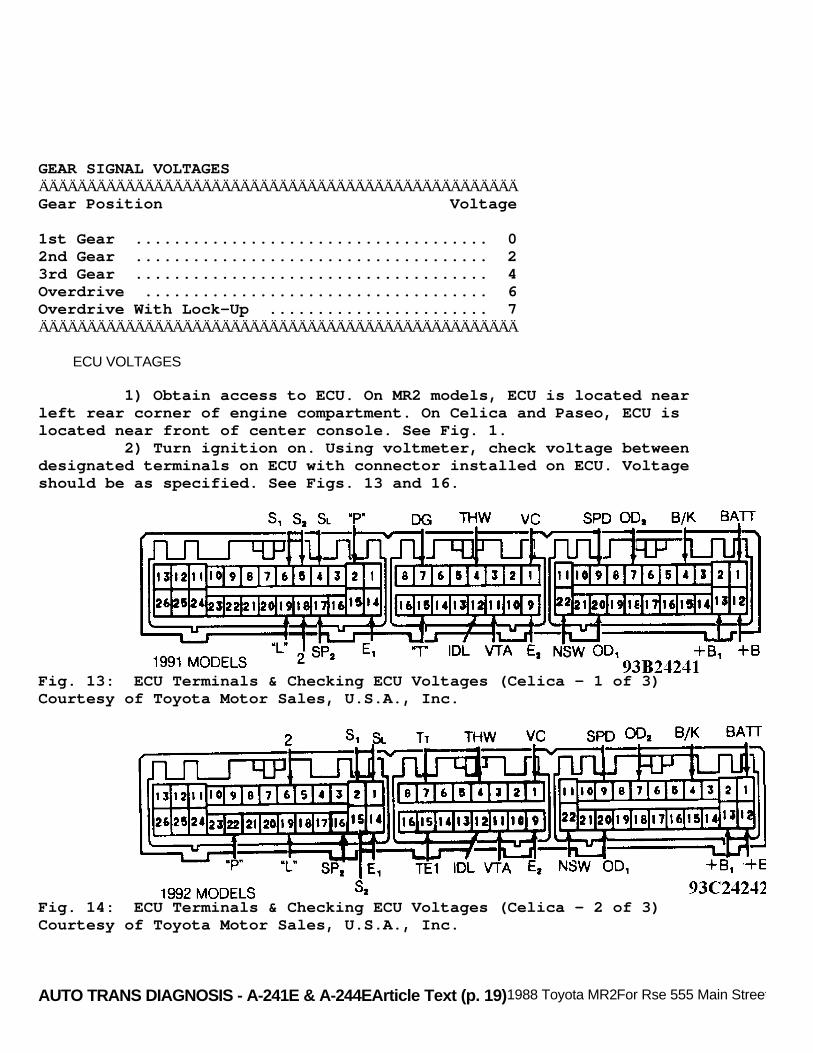
GEAR SIGNAL VOLTAGESÄÄÄÄÄÄÄÄÄÄÄÄÄÄÄÄÄÄÄÄÄÄÄÄÄÄÄÄÄÄÄÄÄÄÄÄÄÄÄÄÄÄÄÄÄÄÄÄÄÄGear Position Voltage
1st Gear ..................................... 02nd Gear ..................................... 23rd Gear ..................................... 4Overdrive .................................... 6Overdrive With Lock-Up ....................... 7ÄÄÄÄÄÄÄÄÄÄÄÄÄÄÄÄÄÄÄÄÄÄÄÄÄÄÄÄÄÄÄÄÄÄÄÄÄÄÄÄÄÄÄÄÄÄÄÄÄÄ
ECU VOLTAGES
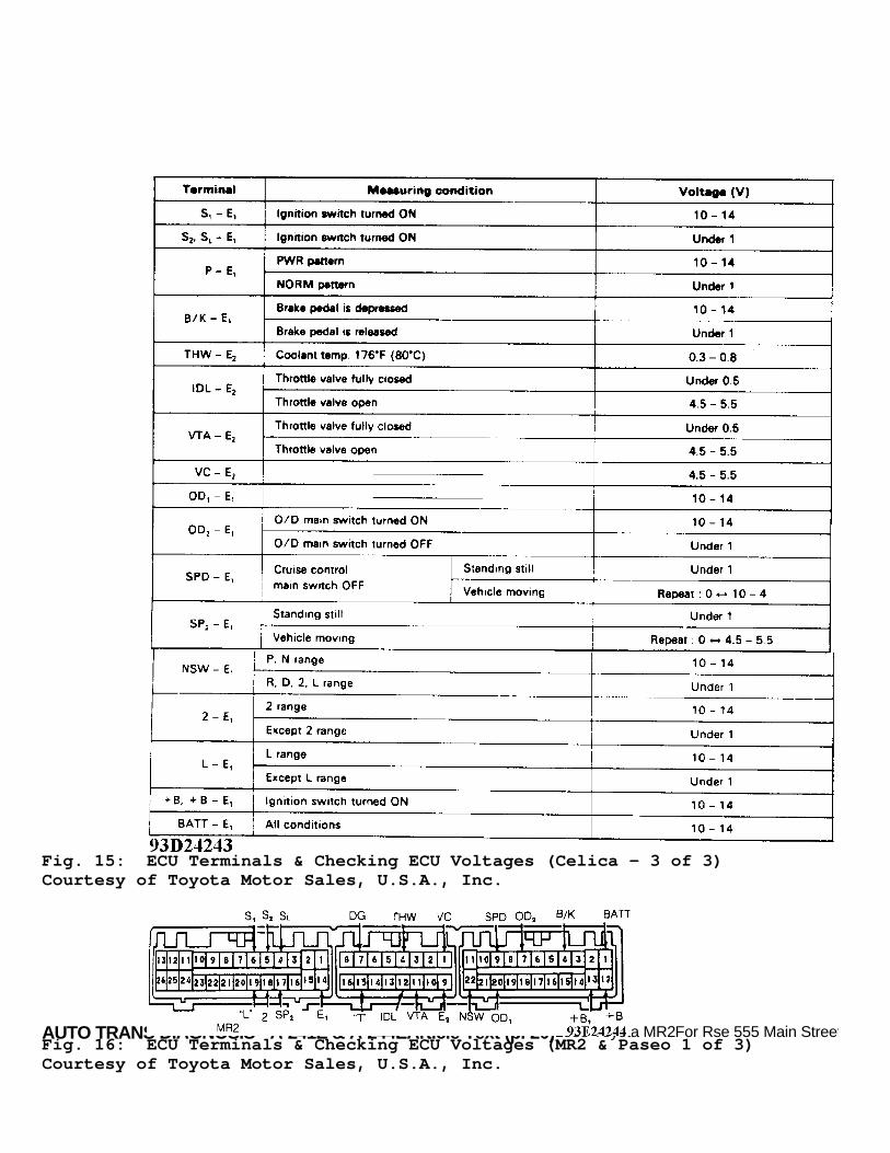
1) Obtain access to ECU. On MR2 models, ECU is located nearleft rear corner of engine compartment. On Celica and Paseo, ECU islocated near front of center console. See Fig. 1. 2) Turn ignition on. Using voltmeter, check voltage betweendesignated terminals on ECU with connector installed on ECU. Voltageshould be as specified. See Figs. 13 and 16.
Fig. 13: ECU Terminals & Checking ECU Voltages (Celica - 1 of 3)Courtesy of Toyota Motor Sales, U.S.A., Inc.
Fig. 14: ECU Terminals & Checking ECU Voltages (Celica - 2 of 3)Courtesy of Toyota Motor Sales, U.S.A., Inc.
AUTO TRANS DIAGNOSIS - A-241E & A-244EArticle Text (p. 20)1988 Toyota MR2For Rse 555 Main Street Clarksville Va 22901
Fig. 15: ECU Terminals & Checking ECU Voltages (Celica - 3 of 3)Courtesy of Toyota Motor Sales, U.S.A., Inc.
Fig. 16: ECU Terminals & Checking ECU Voltages (MR2 & Paseo 1 of 3)Courtesy of Toyota Motor Sales, U.S.A., Inc.

AUTO TRANS DIAGNOSIS - A-241E & A-244EArticle Text (p. 21)1988 Toyota MR2For Rse 555 Main Street Clarksville Va 22901
Fig. 17: ECU Terminals & Checking ECU Voltages (MR2 & Paseo - 2 of 3)Courtesy of Toyota Motor Sales, U.S.A., Inc.
Fig. 18: ECU Terminals & Checking ECU Voltages (MR2 & Paseo - 3 of 3)Courtesy of Toyota Motor Sales, U.S.A., Inc.

AUTO TRANS DIAGNOSIS - A-241E & A-244EArticle Text (p. 22)1988 Toyota MR2For Rse 555 Main Street Clarksville Va 22901
COMPONENT TESTING
SOLENOIDS
NOTE: The No. 1, No. 2 solenoids and lock-up solenoid can be checked. Resistance and operation can be checked with solenoid on the vehicle. Solenoid must be removed from transmission to check solenoid seals.
1) Obtain access to ECU. On MR2 models, ECU is located nearleft rear corner of engine compartment. On Celica and Paseo, ECU islocated near front of center console. See Fig. 1. 2) Ensure ignition is off. Disconnect electrical connectorcontaining the SL, S1 and S2 terminals from ECU. See Figs. 13 and 16.
NOTE: Solenoid terminal identification is as follows: SL, terminal lock-up solenoid; S1, terminal No. 1 solenoid; and S2, terminal No. 2 solenoid.
3) Using ohmmeter, measure resistance between SL, S1 and S2terminal on wiring harness side of ECU connector and body ground forproper solenoid. See Fig. 19. Replace solenoid if resistance is not11-15 ohms. 4) To check solenoid operation, apply battery voltage to SL,S1 and S2 terminal of ECU connector for proper solenoid. Ensureoperating sound can be heard when battery voltage is connected.Replace solenoid if operating sound cannot be heard. 5) To check solenoid seals, connect battery voltage tosolenoid. Apply 71 psi (5 kg/cmý) to solenoid with battery voltageconnected. See Fig. 21. 6) With battery voltage applied, air should pass throughsolenoid. Disconnect battery and ensure air does not pass throughsolenoid. Replace solenoid if defective.
Fig. 19: Identifying Solenoid Terminals (1991 Celica & MR2)Courtesy of Toyota Motor Sales, U.S.A., Inc.

AUTO TRANS DIAGNOSIS - A-241E & A-244EArticle Text (p. 23)1988 Toyota MR2For Rse 555 Main Street Clarksville Va 22901
Fig. 20: Identifying Solenoid Terminals (1992 Celica & Paseo)Courtesy of Toyota Motor Sales, U.S.A., Inc.
Fig. 21: Checking SolenoidsCourtesy of Toyota Motor Sales, U.S.A., Inc.
NEUTRAL START SWITCH
1) Disconnect electrical connector at neutral start switch.Neutral start switch is located on side of transmission. See Fig. 1. 2) Note neutral start switch terminal identification. SeeFig. 22. Using ohmmeter, check for continuity between specifiedterminals in accordance with the shift lever position. Refer to theNEUTRAL START SWITCH CONTINUITY table. Replace neutral start switch ifdefective. Install electrical connector.
NEUTRAL START SWITCH CONTINUITYÄÄÄÄÄÄÄÄÄÄÄÄÄÄÄÄÄÄÄÄÄÄÄÄÄÄÄÄÄÄÄÄÄÄÄÄÄÄÄÄÄÄÄÄÄÄÄÄÄÄShift Lever Position Terminals
Park .............................. 2 & 3, 1 & 6Reverse .................................. 5 & 6Neutral ........................... 2 & 3, 6 & 7"D" ...................................... 6 & 82 ........................................ 6 & 9"L" ...................................... 4 & 6ÄÄÄÄÄÄÄÄÄÄÄÄÄÄÄÄÄÄÄÄÄÄÄÄÄÄÄÄÄÄÄÄÄÄÄÄÄÄÄÄÄÄÄÄÄÄÄÄÄÄ

AUTO TRANS DIAGNOSIS - A-241E & A-244EArticle Text (p. 24)1988 Toyota MR2For Rse 555 Main Street Clarksville Va 22901
Fig. 22: Identifying Neutral Start Switch TerminalsCourtesy of Toyota Motor Sales, U.S.A., Inc.
THROTTLE POSITION SENSOR
1) Disconnect electrical connector at throttle positionsensor, located on side of throttle body. Note throttle positionsensor terminal identification. See Fig. 23. 2) Using ohmmeter, check resistance between specifiedterminals in relation to throttle position. See the specifications inthe THROTTLE POSITION SENSOR RESISTANCE SPECIFICATIONS table. Replacethrottle position sensor if resistance is not as specified.
THROTTLE POSITION SENSOR RESISTANCE SPECIFICATIONSÄÄÄÄÄÄÄÄÄÄÄÄÄÄÄÄÄÄÄÄÄÄÄÄÄÄÄÄÄÄÄÄÄÄÄÄÄÄÄÄÄÄÄÄÄÄÄÄÄÄÄTerminals Ohms
IDL & E2 Throttle Fully Closed ................... 0-100 Throttle Fully Open .................. InfinityVC & E2 ............................... 3000-7000VTA & E2 Throttle Fully Closed ................. 200-800 Throttle Fully Open ............... 3200-10,000ÄÄÄÄÄÄÄÄÄÄÄÄÄÄÄÄÄÄÄÄÄÄÄÄÄÄÄÄÄÄÄÄÄÄÄÄÄÄÄÄÄÄÄÄÄÄÄÄÄÄÄ
Fig. 23: Identifying Throttle Position Sensor TerminalsCourtesy of Toyota Motor Sales, U.S.A., Inc.

AUTO TRANS DIAGNOSIS - A-241E & A-244EArticle Text (p. 25)1988 Toyota MR2For Rse 555 Main Street Clarksville Va 22901
COOLANT TEMPERATURE SENSOR
1) Disconnect electrical connector from coolant temperaturesensor. Coolant temperature sensor is located in coolant passage onengine. See Fig. 1. 2) Using ohmmeter, check resistance between terminals ofcoolant temperature sensor. Resistance should as specified inaccordance with coolant temperature. See Fig. 24. Replace coolanttemperature sensor if resistance is not within specification.
Fig. 24: Checking Coolant Temperature SensorCourtesy of Toyota Motor Sales, U.S.A., Inc.
NO. 1 SPEED SENSOR
1) Remove instrument panel. Connect ohmmeter betweenterminals on rear of instrument panel. See Fig. 25. 2) Rotate speedometer cable shaft on instrument panel. Notethat ohmmeter needle fluctuates from continuity to no continuity. Ifreading does not fluctuate correctly, replace speedometer or speedsensor as necessary.
Fig. 25: Checking No. 1 Speed Sensor (Celica)Courtesy of Toyota Motor Sales, U.S.A., Inc.

AUTO TRANS DIAGNOSIS - A-241E & A-244EArticle Text (p. 26)1988 Toyota MR2For Rse 555 Main Street Clarksville Va 22901
Fig. 26: Checking No. 1 Speed Sensor (MR2)Courtesy of Toyota Motor Sales, U.S.A., Inc.
Fig. 27: Checking No. 1 Speed Sensor (Paseo)Courtesy of Toyota Motor Sales, U.S.A., Inc.
NO. 2 SPEED SENSOR
1) Disconnect electrical connector from No. 2 speed sensor,located on transmission. See Fig. 1. Raise and support vehicle sofront wheels can rotate. Connect ohmmeter between terminals of No. 2speed sensor. 2) Rotate front wheel. Note that ohmmeter needle fluctuatesfrom continuity to no continuity. If reading does not fluctuatecorrectly, remove No. 2 speed sensor from transmission. 3) Connect ohmmeter between terminals of No. 2 speed sensor.Note that ohmmeter needle fluctuates from continuity to no continuitywhen magnet is brought close to speed sensor and then moved away. 4) Replace speed sensor if reading does not fluctuate. Ifreading fluctuates correctly, components in transmission for speedsensor must be replaced.
PATTERN SELECT SWITCH (CELICA ONLY)
1) Disconnect electrical connector from pattern selectswitch, located near shift lever. See Fig. 1. Note terminal

AUTO TRANS DIAGNOSIS - A-241E & A-244E
identification on pattern select switch. See Fig. 28. 2) Using ohmmeter, ensure continuity exists between terminalsNo. 2 and 3 with switch in POWER (depressed) position, and nocontinuity exists with switch in NORMAL (released) position. Replaceswitch if defective.
Fig. 28: Identifying Pattern Select Switch TerminalsCourtesy of Toyota Motor Sales, U.S.A., Inc.
OVERDRIVE (OD) SWITCH
1) Disconnect electrical connector from OD switch, located onshift lever. Note terminal identification on OD switch. See Fig. 29. 2) Using ohmmeter, ensure continuity exists between terminalsNo. 1 and 3 with switch released (OFF position). 3) Ensure no continuity exists between terminals No. 1 and 3with switch depressed (ON position). Replace switch if defective.
Fig. 29: Identifying Overdrive (OD) Switch TerminalsCourtesy of Toyota Motor Sales, U.S.A., Inc.
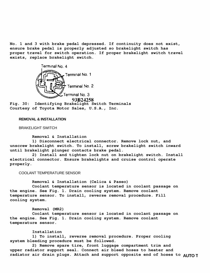
BRAKELIGHT SWITCH
1) Disconnect electrical connector from brakelight switch,located near brake pedal. Note brakelight switch terminalidentification. See Fig. 30. 2) Using ohmmeter, ensure no continuity exists betweenterminals No. 1 and 3 with brake pedal released. Replace brakelightswitch if continuity exists. 3) Using ohmmeter, ensure continuity exists between terminals
AUTO TRANS DIAGNOSIS - A-241E & A-244E
No. 1 and 3 with brake pedal depressed. If continuity does not exist,ensure brake pedal is properly adjusted so brakelight switch hasproper travel for switch operation. If proper brakelight switch travelexists, replace brakelight switch.
Fig. 30: Identifying Brakelight Switch TerminalsCourtesy of Toyota Motor Sales, U.S.A., Inc.
REMOVAL & INSTALLATION
BRAKELIGHT SWITCH
Removal & Installation 1) Disconnect electrical connector. Remove lock nut, andunscrew brakelight switch. To install, screw brakelight switch inwarduntil brakelight plunger contacts brake pedal. 2) Install and tighten lock nut on brakelight switch. Installelectrical connector. Ensure brakelights and cruise control operateproperly.
COOLANT TEMPERATURE SENSOR
Removal & Installation (Celica & Paseo) Coolant temperature sensor is located in coolant passage onthe engine. See Fig. 1. Drain cooling system. Remove coolanttemperature sensor. To install, reverse removal procedure. Fillcooling system.
Removal (MR2) Coolant temperature sensor is located in coolant passage onthe engine. See Fig. 1. Drain cooling system. Remove coolanttemperature sensor.
Installation 1) To install, reverse removal procedure. Proper coolingsystem bleeding procedure must be followed. 2) Remove spare tire, front luggage compartment trim andupper radiator support seal. Connect air bleed hoses to heater andradiator air drain plugs. Attach and support opposite end of hoses to

AUTO TRANS DIAGNOSIS - A-241E & A-244E
hood or hood support. See Fig. 17. Ensure hoses are not pinched. 3) Place heater control lever on instrument panel to warmestposition. Open heater and radiator air drain plugs at least 3 turns. 4) Slowly add coolant through coolant filler. Air will bleedfrom hoses on heater and radiator air drain plugs. Ensure coolant inair bleed hoses and coolant filler are at the same lever. 5) If coolant level in air bleed hoses is lower than lever incoolant filler, air still exists in cooling system. Check for pinchedor restriction in air bleed hoses. If necessary, repeat step 4). Whenproper coolant level is obtained in air bleed hoses, close air drainplugs. Remove air bleed hoses.
Fig. 31: Installing Air Bleed Hoses (MR2)Courtesy of Toyota Motor Sales, U.S.A., Inc.
ELECTRONIC CONTROL UNIT (ECU)
On MR2 models, ECU is located near left rear corner of enginecompartment. See Fig. 1. On Celica and Paseo, ECU is located nearfront of center console. Replacement information not available frommanufacturer.
NO. 1 & NO. 2 SOLENOIDS
Removal & Installation

AUTO TRANS DIAGNOSIS - A-241E & A-244EArticle Text (p. 30)
Solenoids are located on the valve body. See Fig. 1. Removebolt, solenoid and "O" ring from valve body. To install, reverseremoval procedure using NEW "O" ring.
LOCK-UP SOLENOID
Removal & Installation Solenoid is located on the valve body. See Fig. 1. Removebolt, solenoid and "O" ring from valve body. To install, reverseremoval procedure using NEW "O" ring.
NEUTRAL START SWITCH
Removal 1) Neutral start switch is located on side of transmission.Remove lock nut, washer and manual lever from control shaft. SeeFig. 18. 2) Bend up tabs on lock washer. Remove lock nut, lock washerand seal from control shaft. Remove retaining bolts and neutral startswitch.
Installation 1) Install neutral start switch on control shaft. Looselyinstall neutral start switch retaining bolts. Install seal and lockwasher. Install lock nut and tighten to specification. Refer to theTORQUE SPECIFICATIONS table. Bend tabs on lock washer over againstlock nut. 2) Switch must be adjusted. Ensure parking brake is applied.Temporarily install manual lever on control shaft. Place shift leverin Neutral. Remove manual lever. 3) Rotate neutral start switch and align reference mark onneutral start switch with groove. See Fig. 18. Hold neutral switch inthis position. Tighten retaining bolts to specification. To installremaining components, reverse removal procedure.
Fig. 32: Removing & Installing Neutral Start Switch (1 of 2)Courtesy of Toyota Motor Sales, U.S.A., Inc.

AUTO TRANS DIAGNOSIS - A-241E & A-244EArticle Text (p. 31)1988 Toyota MR2For Rse 555 Main Street Clarksville Va 22901
Fig. 33: Removing & Installing Neutral Start Switch (1 of 2)Courtesy of Toyota Motor Sales, U.S.A., Inc.
OVERDRIVE (OD) SWITCH
Overdrive (OD) switch is mounted on the shift lever. SeeFig. 1. Replacement information not available from manufacturer.
PATTERN SELECT SWITCH (CELICA ONLY)
Pattern select switch is located near shift lever. SeeFig. 1. Replacement information not available from manufacturer.
THROTTLE POSITION SENSOR
Removal Ensure ignition is off. Disconnect electrical connector fromthrottle position sensor. Throttle position sensor is located onthrottle body. Remove screws and throttle position sensor.
Installation 1) Install throttle position sensor on throttle body withscrews loosely installed. Throttle position sensor must be adjusted.Connect ohmmeter leads to IDL and E2 terminals of throttle positionsensor. See Fig. 23. 2) Apply vacuum to throttle opener on valve body. SeeFig. 34. Insert a .024" (.60 mm) feeler gauge between throttle stopscrew and stop lever. Gradually rotate throttle position sensor untilohmmeter deflects, and tighten retaining screws. 3) Remove feeler gauge. Insert a .020" (.50 mm) feeler gaugebetween throttle stop screw and stop lever. Ensure continuity nowexists between IDL and E2 terminals. Remove feeler gauge. 4) Insert a .028" (.70 mm) feeler gauge between throttle stopscrew and stop lever. Ensure no continuity now exists between IDL andE2 terminals. Remove feeler gauge.

AUTO TRANS DIAGNOSIS - A-241E & A-244EArticle Text (p. 32)1988 Toyota MR2For Rse 555 Main Street Clarksville Va 22901
Fig. 34: Adjusting Throttle Position SensorCourtesy of Toyota Motor Sales, U.S.A., Inc.
NO. 1 SPEED SENSOR
The No. 1 speed sensor is mounted on rear of instrumentpanel. See Fig. 1. Replacement information not available frommanufacturer.
NO. 2 SPEED SENSOR
Removal Disconnect electrical connector from No. 2 speed sensor,located on transmission. See Fig. 1. Remove bolt, retaining plate andNo. 2 speed sensor. Remove "O" ring from No. 2 speed sensor.
Installation To install, reverse removal procedure using NEW "O" ring.Coat "O" ring with ATF before installing No. 2 speed sensor. Tightenretaining bolt to specification. See TORQUE SPECIFICATIONS.
TORQUE SPECIFICATIONS
TORQUE SPECIFICATIONSÄÄÄÄÄÄÄÄÄÄÄÄÄÄÄÄÄÄÄÄÄÄÄÄÄÄÄÄÄÄÄÄÄÄÄÄÄÄÄÄÄÄÄÄÄÄÄÄÄÄApplication INCH Lbs. (N.m)
Neutral Start Switch Bolt ............... 48 (5)Neutral Start Switch Lock Nut ........... 62 (7)No. 2 Speed Sensor Bolt Celica 2.2L & MR2 (A-241E) ........... 89 (10) Paseo (A-244E) ........................ 48 (5)ÄÄÄÄÄÄÄÄÄÄÄÄÄÄÄÄÄÄÄÄÄÄÄÄÄÄÄÄÄÄÄÄÄÄÄÄÄÄÄÄÄÄÄÄÄÄÄÄÄÄ
WIRING DIAGRAMS

AUTO TRANS DIAGNOSIS - A-241E & A-244EArticle Text (p. 33)1988 Toyota MR2
Fig. 35: Transmission Wiring Diagram (Celica)

AUTO TRANS DIAGNOSIS - A-241E & A-244EArticle Text (p. 34)1988 Toyota MR2For Rse 555 Main Street Clarksville Va 22901
Fig. 36: Transmission Wiring Diagram (MR2)

AUTO TRANS DIAGNOSIS - A-241E & A-244EArticle Text (p. 35)1988 Toyota MR2For Rse 555 Main Street Clarksville Va 22901
Fig. 37: Transmission Wiring Diagram (Paseo)
END OF ARTICLE


![CartemotoneigeSagLac2014-15 [Unlocked by ] sentier lac st-jean.pdf · 6.6 trans-quÉbec 83 trans-quÉbec 93 trans-quÉbec 93 trans-quÉbec 93 trans-quÉbec 93 trans-quÉbec 93 trans-quÉbec](https://static.fdocuments.us/doc/165x107/5b2cb5eb7f8b9ac06e8b5a01/cartemotoneigesaglac2014-15-unlocked-by-sentier-lac-st-jeanpdf-66-trans-quebec.jpg)