Auto Service Station Facility Scenario Example Tier I ... · PDF fileAuto Service Station...
23
Auto Service Station Facility Scenario Example Tier I Qualified Facility SPCC Plan 1 Here is an example of an automotive service station facility and how the owner determines he is covered by the SPCC rule and prepares an SPCC Plan. Description of Gas and Care Express Gas and Care Express located in Malham, Pennsylvania is a self-service gasoline station and automotive service shop offering basic automotive maintenance and repair services, including vehicle safety and emission inspections. The facility is owned and operated by Jack Smith and is located at the intersection of Anywhere and Sideways Streets. An empty lot sits adjacent to the back of the facility. A concrete storm drainage channel runs past one side of the empty lot and conveys storm water into an unnamed creek about a 1/4-mile downstream from this location. The unnamed creek is a tributary of Muddy Creek, which is a tributary to the Susquehanna River. There are four street storm culverts at the intersection where the facility is located. Storm water runoff collected by these culverts is conveyed by the storm sewer into Muddy Creek at an outfall about 1 mile away. Gas and Care Express consists of one main building housing the 3-bay service shop and the sales and customer service area. The facility has two gasoline dispenser islands, each with two dispensers, under a lit canopy. There are three stationary oil Aboveground Storage Tanks (ASTs) at Gas and Care Express. The 1,500-gallon AST for collecting waste oil is a horizontal, cylindrical shop-fabricated tank on concrete saddles resting on a concrete pad within a concrete dike. Constructed in accordance with UL 142, the tank has a direct reading liquid level gauge and a fill pipe with a 5-gallon steel containment sump. The tank fill pipe sump drains back into the tank. Employees transfer waste oil from the collection containers in the shop into this tank using a hand-operated pump. A 275-gallon double-walled AST stores heating oil to heat the service shop during the heating season. A 500-gallon double-walled fire-resistant AST with an on-tank dispenser stores kerosene for sale. Other aboveground storage containers inside the auto service shop are: six single- use rack-mounted 65-gallon drums in a lube oil dispensing system and another six single-use rack-mounted 65-gallon drums for dispensing automatic transmission fluid (3 drums), gear oil (1 drum), and hydraulic oil (2 drums). Each of the three service bays is equipped with a single post swing rail drive-over lift, which has a 42-gallon hydraulic oil reservoir. A filter crusher in the shop has a 30-gallon used oil collection steel drum. The shop collects used antifreeze for recycling in two 30-gallon polyethylene totes. There are two hydraulic floor jacks with hydraulic oil reservoirs that store less than 0.5 pint of oil. Gas and Care Express has an emergency generator to power the gasoline sales operation and the facility lighting during electricity outages. The emergency generator is powered by natural gas but has a 250-gallon Liquid Propane (LP) gas cylinder as a backup fuel. The customer service and auto shop also stocks containers of lube oil, refrigerant oil, brake oil, gear oil, automatic transmission fluid, and power steering fluid products for use and sale. Container sizes range from 8 ounces or ½ pint to 1 gallon. Gasoline is stored in 3-10,000-gallon double-wall steel completely buried Underground Storage Tanks (USTs). These USTs are constructed according to the Underwriters’ Laboratory (UL) 58 standard. The gasoline is transferred to the dispensers through buried, double-walled fiberglass-reinforced plastic fuel transfer piping with interstitial monitoring associated with the USTs. Oil transfer piping at the facility is belowground, except for the aboveground transfer piping and appurtenances at the gasoline dispensers, the kerosene on-tank dispenser, and the gasoline drop fill ports. A fuel supplier delivers gasoline, heating oil, and kerosene via tank trucks. Another supplier fills the shop’s oil products dispensing system 65-gallon drums. A commercial waste hauler periodically comes to the facility to remove both the waste Step 1: Determine if the Gas and Care Express needs an SPCC Plan. Jack Smith, owner of the Gas and Care Express, believes he may have to develop, maintain, and implement a spill prevention plan under the SPCC rule. Let’s walk through the following scenario to determine if he needs an SPCC Plan, and if so, then we need to determine if he is eligible to self‐certify his SPCC Plan and use the Tier I SPCC Plan Template. Is the facility or part of the facility considered non‐transportation‐ related? Yes, the facility stores, uses, and consumes oil—all non‐ transportation related activities. Is the facility engaged in drilling, producing, gathering, storing, processing, refining, transferring, distributing, using, or consuming oil? Yes, the facility stores, uses, and consumes oil. Could the facility reasonably be expected to discharge oil in quantities that may be harmful into navigable waters or adjoining shorelines? Yes, an oil spill from the facility could reach the Muddy Creek which is a tributary of the Susquehanna River. Is the total aggregate capacity of aboveground oil storage containers greater than 1,320 gallons of oil; or is the total aggregate capacity of completely buried storage tanks greater than 42,000 gallons of oil? Yes, the aboveground oil storage capacity is 3,055 gallons. An oil spill from the Gas and Care Express may reach a navigable waterway and the aboveground oil storage capacity is greater than 1,320 gallons. Jack Smith needs to develop an SPCC Plan.
Transcript of Auto Service Station Facility Scenario Example Tier I ... · PDF fileAuto Service Station...

Auto Service Station Facility Scenario Example Tier I Qualified Facility SPCC Plan
1
Here is an example of an automotive service station facility and how the owner determines he is covered by the SPCC rule and prepares an SPCC Plan.
Description of Gas and Care Express
Gas and Care Express located in Malham, Pennsylvania is a self-service gasoline station and automotive service shop offering basic automotive maintenance and repair services, including vehicle safety and emission inspections. The facility is owned and operated by Jack Smith and is located at the intersection of Anywhere and Sideways Streets. An empty lot sits adjacent to the back of the facility. A concrete storm drainage channel runs past one side of the empty lot and conveys storm water into an unnamed creek about a 1/4-mile downstream from this location. The unnamed creek is a tributary of Muddy Creek, which is a tributary to the Susquehanna River. There are four street storm culverts at the intersection where the facility is located. Storm water runoff collected by these culverts is conveyed by the storm sewer into Muddy Creek at an outfall about 1 mile away. Gas and Care Express consists of one main building housing the 3-bay service shop and the sales and customer service area. The facility has two gasoline dispenser islands, each with two dispensers, under a lit canopy.
There are three stationary oil Aboveground Storage Tanks (ASTs) at Gas and Care Express. The 1,500-gallon AST for collecting waste oil is a horizontal, cylindrical shop-fabricated tank on concrete saddles resting on a concrete pad within a concrete dike. Constructed in accordance with UL 142, the tank has a direct reading liquid level gauge and a fill pipe with a 5-gallon steel containment sump. The tank fill pipe sump drains back into the tank. Employees transfer waste oil from the collection containers in the shop into this tank using a hand-operated pump. A 275-gallon double-walled AST stores heating oil to heat the service shop during the heating season. A 500-gallon double-walled fire-resistant AST with an on-tank dispenser stores kerosene for sale.
Other aboveground storage containers inside the auto service shop are: six single-use rack-mounted 65-gallon drums in a lube oil dispensing system and another six single-use rack-mounted 65-gallon drums for dispensing automatic transmission fluid (3 drums), gear oil (1 drum), and hydraulic oil (2 drums). Each of the three service bays is equipped with a single post swing rail drive-over lift, which has a 42-gallon hydraulic oil reservoir. A filter crusher in the shop has a 30-gallon used oil collection steel drum. The shop collects used antifreeze for recycling in two 30-gallon polyethylene totes. There are two hydraulic floor jacks with hydraulic oil reservoirs that store less than 0.5 pint of oil.
Gas and Care Express has an emergency generator to power the gasoline sales operation and the facility lighting during electricity outages. The emergency generator is powered by natural gas but has a 250-gallon Liquid Propane (LP) gas cylinder as a backup fuel. The customer service and auto shop also stocks containers of lube oil, refrigerant oil, brake oil, gear oil, automatic transmission fluid, and power steering fluid products for use and sale. Container sizes range from 8 ounces or ½ pint to 1 gallon.
Gasoline is stored in 3-10,000-gallon double-wall steel completely buried Underground Storage Tanks (USTs). These USTs are constructed according to the Underwriters’ Laboratory (UL) 58 standard.
The gasoline is transferred to the dispensers through buried, double-walled fiberglass-reinforced plastic fuel transfer piping with interstitial monitoring associated with the USTs. Oil transfer piping at the facility is belowground, except for the aboveground transfer piping and appurtenances at the gasoline dispensers, the kerosene on-tank dispenser, and the gasoline drop fill ports.
A fuel supplier delivers gasoline, heating oil, and kerosene via tank trucks. Another supplier fills the shop’s oil products dispensing system 65-gallon drums. A commercial waste hauler periodically comes to the facility to remove both the waste
Step1:DetermineiftheGasandCareExpressneedsanSPCCPlan.
JackSmith,owneroftheGasandCareExpress,believeshemayhavetodevelop,maintain,andimplementaspillpreventionplanundertheSPCCrule.Let’swalkthroughthefollowingscenariotodetermineifheneedsanSPCCPlan,andifso,thenweneedtodetermineifheiseligibletoself‐certifyhisSPCCPlanandusetheTierISPCCPlanTemplate.
Isthefacilityorpartofthefacilityconsiderednon‐transportation‐related?Yes,thefacilitystores,uses,andconsumesoil—allnon‐transportationrelatedactivities.
Isthefacilityengagedindrilling,producing,gathering,storing,processing,refining,transferring,distributing,using,orconsumingoil?Yes,thefacilitystores,uses,andconsumesoil.
Couldthefacilityreasonablybeexpectedtodischargeoilinquantitiesthatmaybeharmfulintonavigablewatersoradjoiningshorelines?Yes,anoilspillfromthefacilitycouldreachtheMuddyCreekwhichisatributaryoftheSusquehannaRiver.
Isthetotalaggregatecapacityofabovegroundoilstoragecontainersgreaterthan1,320gallonsofoil;oristhetotalaggregatecapacityofcompletelyburiedstoragetanksgreaterthan42,000gallonsofoil?
Yes,theabovegroundoilstoragecapacityis3,055gallons.
AnoilspillfromtheGasandCareExpressmayreachanavigablewaterwayandtheabovegroundoilstoragecapacityisgreaterthan1,320gallons.JackSmithneedstodevelopanSPCCPlan.

2
NotethatwhencompletelyburiedtanksaresubjecttotheSPCCrule,theydonotcounttowardtheQualifiedFacility
criteriathreshold.
Step2:DetermineifJackSmithcancertifytheSPCCPlanandcompletethetemplate.
Hasthefacilityhadanyoilspillsthatreachednavigablewatersinthepastthreeyears?Yes,anoilspillfromthisfacilitycananddidreachnavigablewaters.
Wereanyoftheseoilspillslargerthan1,000gallons?No.
Wasoilspilledtonavigablewatersmorethanonceina12‐monthperiod?No,onlyonespillonNovember20,2008reachednavigablewaters(MuddyCreek).
TheMarch7,2010spilldidnotreachnavigablewatersandifitdid,itoccurredmorethan12monthsaftertheNovember20,2008spill.
Didmorethan42gallonsofspilledoilreachnavigablewatersinbothdischarges?No.OnNovember20,2008,only20gallonsreachednavigablewaters.Thevehicleoverfillspillwasontothefacility’sconcretepavementwhereitwascontainedandremoved.Therewasnosingledischargeofoiltonavigablewatersexceeding1,000U.S.gallons,nortwodischargesofoiltonavigablewaterseachexceeding42U.S.gallonswithinanytwelve‐monthperiod.
Istheabovegroundoilstoragecapacity10,000gallonsorless?Yes,GasandCareExpressisaqualifiedfacilityandJackSmithcancertifytheSPCCPlan.
Areanyabovegroundoilstoragecontainersatthefacilitylargerthan5,000gallonscapacity?No.GasandCareExpressisaTierIQualifiedFacilityandJackSmithcancompletetheSPCCPlantemplateinAppendixGoftherule(aslongashedoesnotdeviatefromanyrulerequirements).
Step3:PrepareandimplementanSPCCPlan.SeetherelatedExampleSPCCPlantemplatecompletedforGasandCareExpress.
oil collected in the waste oil AST for disposal and the used antifreeze totes to recycle the antifreeze.
Spill History: The facility had the following discharges in the three years prior to the date that Mr. Smith certified his Plan (07/15/2011):
November 20, 2008 -20 gallon gasoline spill reached the nearest culvert along Sideways Street and into Muddy Creek;
March 7, 2010 – Contained 1 gallon gasoline spill to dispensing area concrete pavement (customer overfilled vehicle).
Oil Container Inventory: Below is a breakdown of the oil storage containers at the Gas and Care Express and how the SPCC rule applies to each oil storage container.
The following containers are subject to the SPCC rule: 1,500-gallon waste oil AST (stationary
aboveground bulk storage container)
275-gallon heating oil AST (only heating oil tanks used solely at single-family homes are exempt from the SPCC rule)
500-gallon kerosene AST (stationary aboveground bulk storage container)
Oil products rack dispensing system (includes twelve 65-gallon oil drums, total capacity = 780 gallons)
Facility Total AST capacity 1,500+275+500+780 = 3,055 gallons
Exempt containers do not count toward the facility total oil storage capacity and are not subject to any SPCC rule requirements (though the owner or operator must still prevent spills from these containers and report any spills that reach navigable waters or adjoining shorelines).
The following containers are exempt from the SPCC rule: Three 10,000-gallon completely buried gasoline USTs
These containers are exempt because they are subject to the technical requirements of the UST rule (see 40 CFR 280 or 281)
Any bulk storage container or oil-filled operational equipment that has a capacity of less than 55 gallons:
Two 30-gallon used antifreeze totes,
30-gallon oil filter crusher drum,
42-gallon post lift hydraulic oil reservoirs,
0.5 pint floor jack hydraulic oil reservoirs, and
Containers ranging from 0.5 pint to 1 gallon capacity of lube oil, refrigerant oil, brake oil, gear oil, automatic transmission fluid, and power steering fluid products
250-gallon LP gas tank for the emergency generator (the SPCC rule does not regulate gases)
Stationaryandmobileorportableabovegroundoil
storagecontainersaresubjecttotheSPCCruleandcounttowardtheQualifiedFacility
criteriathreshold.

2 dispensing islands
with 2 gasoline
dispensers per island
under canopy
Area BSales and
customer
service
Area A3-bay service shop
Self-service
auto vacuum
area
1,500-gal Waste Oil AST #1
3 - 10,000-gal USTs
Fence
Hedge
Bollards
Anywhere StreetS
ide
wa
ys S
tree
t
Storm culvert
Concrete storm water drainage channel To an unnamed creek about ¼ mile away
Sidewalk
Shopping Center
Mixed
development
Undeveloped lot
Concrete
pavement
Buried double-walled
fiberglass piping between
dispensers and USTs
Distance to drainage channel
across lot is about 200 ft down
gradient from the fence
Service Shop Area A
· 65-gal lube oil steel drum, rack-mounted, 6 ea
· 65-gal other auto service oil drum, rack-mounted, 6 ea (automatic transmission fluid- 3ea,
gear oil- 1 ea, and hydraulic oil- 2 ea)
· 30-gal used antifreeze collection polyethylene tote, 2 ea
· 30-gal used filter oil collection steel drum, 1 ea
· 42-gal hydraulic drive over lift oil reservoir, 3 ea
· 0.5 pint hydraulic floor jack oil reservoir, 2 ea
· ½ pint to 1 gallon containers of refrigerant oil, gear oil, automatic transmission fluid, antifreeze,
and power steering fluid products for servicing vehicles
· Spill kit, shop vacuum, and drip pans
Sales and Customer Service Area B
· ½ pint to 1 gallon containers of lube oil,
brake oil, gear oil, automatic transmission
fluid, antifreeze and power steering fluid
products for sale
· Spill kit
· UST and piping leak detection and
Automatic Tank Gauge (ATG) control and
monitoring system instrumentation, pump
controls, and emergency shutoffs
Spill kit
Spill kit
Drainage direction
To nearest culverts 150 ft
away
Tier I Template SPCC Plan – Gas and Care Express Service Statiion
This facility diagram is only for illustrating the example facility to help readers visualize the information in the scenario and the sample SPCC Plan. Inclusion
of a facility diagram in the SPCC Plan is not a requirement for a Tier I Qualified Facility opting to complete the Tier I Qualified Facility SPCC Plan Template.
Parking area
Storm water collected in
these culverts outfall 1
mile away into Muddy
Creek
Storm water collected in
these culverts outfall 1
mile away into Muddy
Creek
250 gal LPG tank
LPG/NG
Generator
Tank Truck Gasoline
Unload Area
275-gal Heating Oil
AST #2
Tank Truck
Heating Oil
Unload Area
500-gal Kerosene AST #3
Tank Truck
Kerosene
Unload
Area
Drainage direction

U.S. ENVIRONMENTAL PROTECTION AGENCY TIER I QUALIFIED FACILITY SPCC PLAN TEMPLATE *Please note: Editorial comments for the purposes of this guidance document are identified by red italicized text to distinguish this information from the template text.*
Instructions to Complete this Template This template is intended to help the owner or operator of a Tier I qualified facility develop a self-certified Spill Prevention, Control, and Countermeasure (SPCC) Plan. To use this template, your facility must meet all of the applicability criteria of a Tier I qualified facility listed under §112.3(g)(1) of the SPCC rule. This template provides every SPCC rule requirement necessary for a Tier I qualified facility, which you must address and implement.
You may use this template to comply with the SPCC regulation or use it as a model and modify it as necessary to meet your facility-specific needs. If you modify the template, your Plan must include a section cross-referencing the location of each applicable requirement of the SPCC rule and you must ensure that your Plan is an equivalent Plan that meets all applicable rule requirements of 40 CFR 112.6(a)(3).
You may complete this template either electronically or by hand on a printed copy. This document is a reformatted version of the template found in Appendix G of 40 CFR part 112.a No substantive changes have been made. Please note that a "Not Applicable" ("N/A") column has been added to both Table G-10 (General Rule Requirements for Onshore Facilities) and Table G-11 (General Rule Requirements for Onshore Oil Production Facilities). The "N/A" column should help you complete your self-certification when a required rule element does not apply to your facility. Use of the "N/A" column is optional and is not required by rule.
All Tier I qualified facility self-certifiers must complete Sections I, II, and III. Additionally, the owner or operator of an:
Onshore facility (excluding production) must complete Section A. Onshore oil production facility (excluding drilling and workover facilities) must complete Section B. Onshore oil drilling and workover facility must complete Section C.
This example Plan does not include Sections B and C. These sections are not applicable to the facility addressed in this sample Plan.
Complete and include with your Plan the appropriate attachments. You should consider printing copies of the attachments for use in implementing the SPCC Plan (e.g. Attachment 3.1 - Inspection Log & Schedule; Attachment 4 - Discharge Notification Form).
To complete the template, check the box next to the requirement to indicate that it has been adequately addressed. Either write “N/A” in the column or check the box under the “N/A” column to indicate those requirements that are not applicable to the facility. Where a section requires a description or listing, write in the spaces provided (or attach additional descriptions if more space is needed).
Below is a key for the colors used in the section headers:
Sections I, II, and III: Required for all Tier I qualified facilities
Section A: Onshore facilities (excluding production)
Section B: Onshore oil production facilities (excluding drilling and workover facilities)
Section C: Onshore oil drilling and workover facilities
Attachments: 1 - Five Year Review and Technical Amendment Logs 2 - Oil Spill Contingency Plan and Checklist 3 - Inspections, Dike Drainage and Personnel Training Logs 4 - Discharge Notification Form
After you have completed all appropriate sections, certify and date your Plan, and then implement it by the compliance date. If your facility was in operation before August 16, 2002, and you do not already have a Plan, then implement this template immediately. Conduct inspections and tests in accordance with the written procedures that you have developed for your facility. You must keep with the SPCC Plan a record of these inspections and tests, signed by the appropriate supervisor or inspector, for a period of three years.
Do not forget to periodically review your Plan (at least once every five years) or to update it when you make changes to your facility. You must prepare amendments within six months of the facility change, and implement them as soon as possible, but not later than six months following any amendment.
In the event that your facility releases oil to navigable waters or adjoining shorelines, immediately call the National Response Center (NRC) at 1-800-424-8802. The NRC is the federal government's centralized reporting center, which is staffed 24 hours per day by U.S. Coast Guard personnel.
a Please note that the use of this template is not mandatory for a Tier I qualified facility. You may also meet the SPCC Plan requirement by preparing a satisfactory Tier II qualified facility Plan, preparing a satisfactory Plan that is certified by a Professional Engineer, or by developing an equivalent Plan for a Tier I qualified facility. Further information on the requirements of these methods can be found in 40 CFR part 112.6(a)(1). If you use any of these alternative methods you must include a cross reference in your Plan that shows how the equivalent Plan meets all applicable 40 CFR part 112 requirements.

Page 1 Tier I Qualified Facility SPCC Plan Facility Name: Gas and Care Express
Facility information in this example SPCC Plan is identified by blue text to distinguish this information from the template text.
This template constitutes the SPCC Plan for the facility, when completed and signed by the owner or operator of a facility that meets the applicability criteria in §112.3(g)(1). This template addresses the requirements of 40 CFR Part 112. Maintain a complete copy of the Plan at the facility if the facility is normally attended at least four hours per day, or for a facility attended fewer than four hours per day, at the nearest field office. When making operational changes at a facility that are necessary to comply with the rule requirements, the owner/operator should follow state and local requirements (such as for permitting, design and construction) and obtain professional assistance, as appropriate.
Facility Description
I. Self-Certification Statement (§112.6(a)(1))
The owner or operator of a facility certifies that each of the following is true in order to utilize this template to comply with the SPCC requirements:
I Jack Smith certify that the following is accurate:
1. I am familiar with the applicable requirements of 40 CFR part 112; 2. I have visited and examined the facility; 3. This Plan was prepared in accordance with accepted and sound industry practices and standards; 4. Procedures for required inspections and testing have been established in accordance with industry inspection
and testing standards or recommended practices; 5. I will fully implement the Plan; 6. This facility meets the following qualification criteria (under §112.3(g)(1)):
a. The aggregate aboveground oil storage capacity of the facility is 10,000 U.S. gallons or less; and b. The facility has had no single discharge as described in §112.1(b) exceeding 1,000 U.S. gallons and no
two discharges as described in §112.1(b) each exceeding 42 U.S. gallons within any twelve month period in the three years prior to the SPCC Plan self-certification date, or since becoming subject to 40 CFR part 112 if the facility has been in operation for less than three years (not including oil discharges as described in §112.1(b) that are the result of natural disasters, acts of war, or terrorism); and
c. There is no individual oil storage container at the facility with an aboveground capacity greater than 5,000 U.S. gallons.
7. This Plan does not deviate from any requirement of 40 CFR part 112 as allowed by §112.7(a)(2) (environmental equivalence) and §112.7(d) (impracticability of secondary containment) or include any measures pursuant to §112.9(c)(6) for produced water containers and any associated piping;
8. This Plan and individual(s) responsible for implementing this Plan have the full approval of management and I have committed the necessary resources to fully implement this Plan.
Facility Name Gas and Care Express
Facility Address 345 Anywhere Street
City Malham State PA ZIP 17400
County York Tel. Number (717) 888 – 7777
Owner or Operator Name Jack Smith
Owner or Operator Address 18 Anywhere Street
City Malham State PA ZIP 17400
County York Tel. Number (717) 888 – 6060
Owner or operator Name Same as above
Owner or Operator Address Same as above
City State ZIP
County Tel. Number
Tier I Qualified Facility SPCC Plan

Page 2 Tier I Qualified Facility SPCC Plan Facility Name: Gas and Care Express
I also understand my other obligations relating to the storage of oil at this facility, including, among others:
1. To report any oil discharge to navigable waters or adjoining shorelines to the appropriate authorities. Notification information is included in this Plan.
2. To review and amend this Plan whenever there is a material change at the facility that affects the potential for an oil discharge, and at least once every five years. Reviews and amendments are recorded in an attached log. [See Five Year Review Log and Technical Amendment Log in Attachments 1.1 and 1.2.]
3. Optional use of a contingency plan. A contingency plan: a. May be used in lieu of secondary containment for qualified oil-filled operational equipment, in accordance
with the requirements under §112.7(k), and; This sample Tier I template SPCC Plan contains an oil spill contingency plan in Attachment 2 that follows the provisions of 40 CFR 109. However, the facility does not have oil-filled operational equipment that are 55 gallons or greater in capacity; therefore, the contingency plan is not applicable for this scenario (so the checkboxes in Attachment 2 are not filled in). If the facility had regulated oil-filled operational equipment with containers that are 55 gallons or greater and the equipment met the criteria under §112.7(k), the facility has the option to use the contingency plan in Attachment 2 instead of general secondary containment for the equipment.
b. Must be prepared for flowlines and/or intra-facility gathering lines which do not have secondary containment at an oil production facility, and;
c. Must include an established and documented inspection or monitoring program; must follow the provisions of 40 CFR part 109; and must include a written commitment of manpower, equipment and materials to expeditiously remove any quantity of oil discharged that may be harmful. If applicable, a copy of the contingency plan and any additional documentation will be attached to this Plan as Attachment 2.
I certify that I have satisfied the requirement to prepare and implement a Plan under §112.3 and all of the requirements under §112.6(a). I certify that the information contained in this Plan is true.
Signature Jack Smith Title: Owner Name Jack Smith Date: 07 / 15 / 2011
II. Record of Plan Review and Amendments
Five Year Review (§112.5(b)): Complete a review and evaluation of this SPCC Plan at least once every five years. As a result of the review, amend
this Plan within six months to include more effective prevention and control measures for the facility, if applicable. Implement any SPCC Plan amendment as soon as possible, but no later than six months following Plan amendment. Document completion of the review and evaluation, and complete the Five Year Review Log in Attachment 1.1. If the facility no longer meets Tier I qualified facility eligibility, the owner or operator must revise the Plan to meet Tier II qualified facility requirements, or complete a full PE certified Plan.
Table G-1 Technical Amendments (§§112.5(a), (c) and 112.6(a)(2)) This SPCC Plan will be amended when there is a change in the facility design, construction, operation, or maintenance that materially affects the potential for a discharge to navigable waters or adjoining shorelines. Examples include adding or removing containers, reconstruction, replacement, or installation of piping systems, changes to secondary containment systems, changes in product stored at this facility, or revisions to standard operating procedures.
Any technical amendments to this Plan will be re-certified in accordance with Section I of this Plan template. [§112.6(a)(2)] [See Technical Amendment Log in Attachment 1.2]
Page 3 Tier I Qualified Facility SPCC Plan Facility Name: Gas and Care Express
III. Plan Requirements
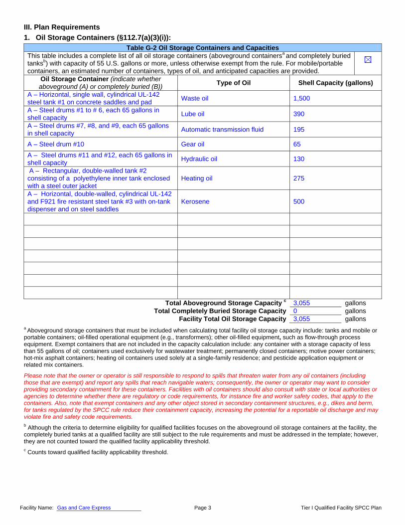
1. Oil Storage Containers (§112.7(a)(3)(i)):
a Aboveground storage containers that must be included when calculating total facility oil storage capacity include: tanks and mobile or portable containers; oil-filled operational equipment (e.g., transformers); other oil-filled equipment, such as flow-through process equipment. Exempt containers that are not included in the capacity calculation include: any container with a storage capacity of less than 55 gallons of oil; containers used exclusively for wastewater treatment; permanently closed containers; motive power containers; hot-mix asphalt containers; heating oil containers used solely at a single-family residence; and pesticide application equipment or related mix containers.
Please note that the owner or operator is still responsible to respond to spills that threaten water from any oil containers (including those that are exempt) and report any spills that reach navigable waters; consequently, the owner or operator may want to consider providing secondary containment for these containers. Facilities with oil containers should also consult with state or local authorities or agencies to determine whether there are regulatory or code requirements, for instance fire and worker safety codes, that apply to the containers. Also, note that exempt containers and any other object stored in secondary containment structures, e.g., dikes and berm, for tanks regulated by the SPCC rule reduce their containment capacity, increasing the potential for a reportable oil discharge and may violate fire and safety code requirements. b Although the criteria to determine eligibility for qualified facilities focuses on the aboveground oil storage containers at the facility, the completely buried tanks at a qualified facility are still subject to the rule requirements and must be addressed in the template; however, they are not counted toward the qualified facility applicability threshold. c Counts toward qualified facility applicability threshold.
Table G-2 Oil Storage Containers and CapacitiesThis table includes a complete list of all oil storage containers (aboveground containersa and completely buried tanksb) with capacity of 55 U.S. gallons or more, unless otherwise exempt from the rule. For mobile/portable containers, an estimated number of containers, types of oil, and anticipated capacities are provided.
Oil Storage Container (indicate whether aboveground (A) or completely buried (B)) Type of Oil Shell Capacity (gallons)
A – Horizontal, single wall, cylindrical UL-142 steel tank #1 on concrete saddles and pad
Waste oil 1,500
A – Steel drums #1 to # 6, each 65 gallons in shell capacity
Lube oil 390
A – Steel drums #7, #8, and #9, each 65 gallons in shell capacity
Automatic transmission fluid 195
A – Steel drum #10 Gear oil 65
A – Steel drums #11 and #12, each 65 gallons in shell capacity
Hydraulic oil 130
A – Rectangular, double-walled tank #2 consisting of a polyethylene inner tank enclosed with a steel outer jacket
Heating oil 275
A – Horizontal, double-walled, cylindrical UL-142 and F921 fire resistant steel tank #3 with on-tank dispenser and on steel saddles
Kerosene 500
Total Aboveground Storage Capacity c 3,055 gallons Total Completely Buried Storage Capacity 0 gallons
Facility Total Oil Storage Capacity 3,055 gallons

Page 4 Tier I Qualified Facility SPCC Plan Facility Name: Gas and Care Express
2. Secondary Containment and Oil Spill Control (§§112.6(a)(3)(i) and (ii), 112.7(c) and 112.9(c)(2)):
Table G-3 Secondary Containment and Oil Spill Control Appropriate secondary containment and/or diversionary structures or equipmenta is provided for all oil handling containers, equipment, and transfer areas to prevent a discharge to navigable waters or adjoining shorelines. The entire secondary containment system, including walls and floor, is capable of containing oil and is constructed so that any discharge from a primary containment system, such as a tank or pipe, will not escape the containment system before cleanup occurs.
a Use one of the following methods of secondary containment or its equivalent: (1) Dikes, berms, or retaining walls sufficiently impervious to contain oil; (2) Curbing; (3) Culverting, gutters, or other drainage systems; (4) Weirs, booms, or other barriers; (5) Spill diversion ponds; (6) Retention ponds; or (7) Sorbent materials. At an SPCC-regulated facility, all areas with the potential for discharging oil must comply with the general secondary containment requirements specified in §112.7(c). In this scenario, the following areas are subject to the general secondary containment requirements:
Oil transfer areas (e.g., the gasoline dispenser islands, the kerosene dispenser, the tank truck fuel unloading areas, and the filling of service oil dispensing drums inside the shop),
Aboveground transfer equipment (e.g., the fuel and automotive service oil dispensing hoses and appurtenances), and
Oil storage containers with a capacity of 55 gallons or greater and associated appurtenances (e.g., overfill vents on double-walled tanks)
Secondary containment structures, e.g., dikes or berms, can be constructed with various materials such as: metal, concrete, earthen materials, liners, asphalt, and other coatings. Although different materials can be used, the material and containment construction must enable the secondary containment structure to prevent discharges to navigable waters or adjoining shorelines. For the secondary containment structure to serve this purpose, it must be able to contain the oil spill until it is cleaned up. Whether it can do this depends primarily on the ability of the containment material to slow down or prevent the flow of the spill through the material, (i.e., the material’s imperviousness to the spill). Note that the rule does not specify how to design the secondary containment system to meet the impervious standard. The facility owner or operator determines how best to provide secondary containment based on good industry practices, oil product properties, and other specific factors and conditions at the facility.
Appropriate general secondary containment for these areas must address the most likely oil discharge from the equipment and prevent the discharge from escaping containment until it is cleaned up. A facility owner or operator can use active containment measures that require deployment of response equipment or other specific action by the facility personnel to prevent the discharge from reaching navigable waters or adjoining shorelines. These measures must be able to contain the most likely oil discharge volume, and personnel and equipment must be available to timely and effectively carry out the active containment measure measures to contain the most likely oil discharge volume.
In the scenario, the facility uses active containment measures for several areas that have a potential for discharging oil. Personnel attend and monitor all oil transfer operations, spill kits are available and maintained within easy reach at each transfer area, and the containment equipment can contain the most likely discharge volumes at each area.
Note that EPA considers that shop-fabricated double-walled tanks that employ overfill and leak detection measures and are constructed to industry standards address the secondary containment requirements in the SPCC rule. This clarification can be found in EPA Memorandum, Subject: Use of Alternative Secondary Containment Measures at Facilities Regulated under the Oil Pollution Prevention Regulation (40 CFR Part 112), OSWER 9360.8-38, More detailed information on secondary containment, including design and construction, is available in the SPCC Guidance for Regional Inspectors, EPA 550-B-05-001, at www.epa.gov/emergencies/content/spcc/spcc_guidance.htm.

Ver. 1-E-doc-3-18-10
Page 5 Tier I Qualified Facility SPCC Plan
Table G-4 below identifies the tanks and containers at the facility with the potential for an oil discharge; the mode of failure; the flow direction and potential quantity of the discharge; and the secondary containment method and containment capacity that is provided.
Table G-4 Containers with Potential for an Oil Discharge
Area Type of failure (discharge scenario)
Potential discharge volume (gallons)
Direction of flow for uncontained discharge
Secondary containment methoda
Secondary containment capacity (gallons)
Bulk Storage Containers and Mobile/Portable Containersb
1,500 gal waste oil tank #1 Tank overfill, fitting leak, seam failure
<1 – 1,500 South to undeveloped lot
Concrete pad and dike
2,356
65 gal lube oil drums #1 to #6 (inside shop) Fitting leak, seam failure <1 – 65 To shop floor Steel leak tray 80
65 gal other oil product drums #7 to #12 (inside shop)
Fitting leak, seam failure <1 – 65 To shop floor Steel leak tray 80
Heating oil tank #2 Tank overfill, fitting leak, seam failure
<1 – 275 South to undeveloped lot
Double wall 280
Kerosene tank #3 Tank overfill, fitting leak, seam failure
<1 – 500 South to undeveloped lot
Double wall 515
Oil-filled Operational Equipment (e.g., hydraulic equipment, transformers)c None with container > 55 gallons Piping, Valves, etc.
Oil dispensing hoses and appurtenances (inside shop)
Fitting leak or failure, hose failure < 1 To shop floor Spill kit and drip pans
Absorbs up to 30/pans contain up to 2
Product Transfer Areas (location where oil is loaded to or from a container, pipe or other piece of equipment.)
Automotive oil servicing in shop and filling oil dispensing system drums
Handling drips and spills, drum overfill, transfer hose failure
<1 pt – 0.5 To shop floor Catch pans and spill kit
Absorbs up to 30/pans contain up to 2
Gasoline, heating oil, and kerosene unload areas
Receiving tank overfill, fitting leak or failure, fuel transfer hose failure
1 – 20 Radial to concrete pavement
Spill kit Absorbs up to 30
Gasoline dispensing island Vehicle gas tank overfill, fitting leak or failure, fuel transfer hose failure
1 – 2 Radial to concrete pavement
Spill kit Absorbs up to 45
Kerosene dispensing Portable container overfill, fitting leak or failure, fuel transfer hose failure
< 0.5 Radial to concrete pavement
Spill kit Absorbs up to 30
Other Oil-Handling Areas or Oil-Filled Equipment (e.g. flow-through process vessels at an oil production facility) None
a Use one of the following methods of secondary containment or its equivalent: (1) Dikes, berms, or retaining walls sufficiently impervious to contain oil; (2) Curbing; (3) Culverting, gutters, or other drainage systems; (4) Weirs, booms, or other barriers; (5) Spill diversion ponds; (6) Retention ponds; or (7) Sorbent materials. b For storage tanks and bulk storage containers, the secondary containment capacity must be at least the capacity of the largest container plus additional capacity to contain rainfall or other precipitation. c For oil-filled operational equipment: Document in the table above if alternative measures to secondary containment (as described in §112.7(k)) are implemented at the facility.
See the companion secondary containment calculation worksheet for the 1,500-gal tank’s secondary containment system.
Facility Name: Gas and Care Express

Ver. 1-E-doc-3-18-10
Page 6 Tier I Qualified Facility SPCC Plan Facility Name: Gas and Care Express
3. Inspections, Testing, Recordkeeping and Personnel Training (§§112.7(e) and (f), 112.8(c)(6) and (d)(4), 112.9(c)(3), 112.12(c)(6) and (d)(4)):
Table G-5 Inspections, Testing, Recordkeeping and Personnel Training An inspection and/or testing program is implemented for all aboveground bulk storage containers and piping at this facility. [§§112.8(c)(6) and (d)(4), 112.9(c)(3), 112.12(c)(6) and (d)(4)]
The following is a description of the inspection and/or testing program (e.g., reference to industry standard utilized, scope, frequency, method of inspection or test, and person conducting the inspection) for all aboveground bulk storage containers and piping at this facility:
1) All employees are trained to do visual inspections of oil storage and transfer areas and equipment. An assigned knowledgeable employee does periodic visual inspections of the aboveground oil storage containers using Attachment 3.1 to document inspections; records of inspections consist of the monthly inspection checklist and the annual inspection checklist in the Steel Tank Institute (STI) SP001 inspection standard. Visual inspections of oil storage containers follow the inspection schedule in Attachment 3.2 of this plan.
2) The liquid level gauges on the waste oil AST, heating oil AST, and kerosene AST are inspected and calibrated at least annually following the manufacturer’s procedures by a qualified technician. The heating oil AST’s mechanical vent whistle is tested with each delivery of fuel oil; the kerosene AST’s liquid level gauge-activated high-level alarm is inspected monthly and functionally tested annually following manufacturer’s procedures by a qualified employee. Attachment 3.1 documents these inspections.
3) An assigned employee also visually inspects the dispensers on the kerosene AST and at the gasoline island for indications of deterioration and discharges, including the transfer hoses, valves, and other fittings, at least daily following the manufacturer’s procedures.
4) Employees inspect the 1,500 gal waste oil tank concrete dike on a weekly basis for signs of deterioration, discharges (e.g., from tank leaking fittings or seams and transfer spills), or accumulation of oil. In addition, employees inspect the dike containment after any heavy rainfall. These inspections are documented in Attachment 3.1. The dike containment does not have a drain for storm water. Collected rain is pumped from the dike containment and discharged to the ground only after the inspection shows that there is no oil or oil sheen present in the rainwater collected in the dike. If oil or oil sheen is detected on rainwater in the dike, the oily rainwater is pumped into the 1,500-gal waste oil tank for disposal by the waste oil hauler contractor or the contractor is requested to remove the oily rainwater in the dike for disposal. Each drainage activity is recorded in Attachment 3.3. Record keeping for disposal of waste oil or oil-contaminated water accumulated in the berm area is in Attachment 3.3 of this plan.
5) If an employee encounters a spill during an inspection of the oil storage or transfer equipment, the employee will immediately take the necessary actions outlined in Table G-7.
6) An assigned employee inspects spill kits monthly to check equipment serviceability and ensure fully stocked kits.
Inspections, tests, and records are conducted in accordance with written procedures developed for the facility. Records of inspections and tests kept under usual and customary business practices will suffice for purposes of this paragraph. [§112.7(e)]
A record of the inspections and tests are kept at the facility or with the SPCC Plan for a period of three years. [§112.7(e)] [See Inspection Log and Schedule in Attachment 3.1]
Inspections and tests are signed by the appropriate supervisor or inspector. [§112.7(e)]
Personnel, training, and discharge prevention procedures [§112.7(f)] Oil-handling personnel are trained in the operation and maintenance of equipment to prevent discharges; discharge procedure protocols; applicable pollution control laws, rules, and regulations; general facility operations; and, the contents of the facility SPCC Plan. [§112.7(f)]
A person who reports to facility management is designated and accountable for discharge prevention. [§112.7(f)]
Name/Title: James Fixer / Head Mechanic
Discharge prevention briefings are conducted for oil-handling personnel annually to assure adequate understanding of the SPCC Plan for that facility. Such briefings highlight and describe past reportable discharges or failures, malfunctioning components, and any recently developed precautionary measures. [§112.7(f)] [See Oil-handling Personnel Training and Briefing Log in Attachment 3.4]

Ver. 1-E-doc-3-18-10
Page 7 Tier I Qualified Facility SPCC Plan Facility Name: Gas and Care Express
4. Security (excluding oil production facilities) §112.7(g): Table G-6 Implementation and Description of Security Measures
Security measures are implemented at this facility to prevent unauthorized access to oil handling, processing, and storage area.
The following is a description of how you secure and control access to the oil handling, processing and storage areas; secure master flow and drain valves; prevent unauthorized access to starter controls on oil pumps; secure out-of-service and loading/unloading connections of oil pipelines; address the appropriateness of security lighting to both prevent acts of vandalism and assist in the discovery of oil discharges: 1) The facility is open for gasoline and kerosene sales 24 hours every day and is attended around the clock. 2) All tank fill pipes are capped and locked when not in use; tanks do not have drain valves. 3) The automotive maintenance shop is open for service for 10 hours, Monday through Saturday, and the shop is
locked outside business hours. 4) The dispenser pump controls are inside the gasoline sales and customer service area, attended 24 hours every
day, in a locked utility room. The attendant can shut off pumps remotely from the attendant station in the sales and customer service area; the entrance to the attendant station is kept locked when the automotive maintenance shop is closed.
5) The kerosene on-tank dispenser pump control is kept locked and only facility employees are authorized to unlock, turn the pump on, and transfer kerosene into customer containers.
6) The gasoline dispensing island is lit and all facility entrances have security lights above and outside the entrances. There are also wall-mounted flood lamps that illuminate the 1,500-gal waste oil, heating oil, and kerosene AST locations.
5. Emergency Procedures and Notifications (§112.7(a)(3)(iv) and 112.7(a)(5)):
Table G-7 Description of Emergency Procedures and Notifications The following is a description of the immediate actions to be taken by facility personnel in the event of a discharge to navigable waters or adjoining shorelines [§112.7(a)(3)(iv) and 112.7(a)(5)]: 1) Shutdown pumping in event of a spill during any fuel transfer operation or an emergency at the fuel dispensers. 2) Eliminate potential sources of ignition such as open flames or sparks. 3) If possible, safe, and trained to do so, identify and secure source of the discharge and contain the discharge with
sorbents, sandbags, or other material from the spill kits.
a. The main and largest spill kit is kept in the attendant area. b. The second spill kit is kept behind the service shop. c. The third spill kit is kept inside the service shop. d. The fourth spill kit is kept between the 1,500-gal waste oil AST dike and the 500-gal kerosene AST.
4) Contact regulatory authorities and other response personnel and organizations (see next page).

Ver. 1-E-doc-3-18-10
Page 8 Tier I Qualified Facility SPCC Plan Facility Name: Gas and Care Express
6. Contact List (§112.7(a)(3)(vi)):
Table G-8 Contact List Contact Organization / Person Telephone Number
National Response Center (NRC) 1-800-424-8802 Cleanup Contractor(s) RO Co. (Waste Oil Disposal Contractor) Owners or operators of SPCC-regulated facilities are not required to have signed contracts or agreements with cleanup contractors under the SPCC rule. Although no formal written agreement to respond is required by the SPCC rule, the owner or operator must identify phone numbers for the facility response coordinator, National Response Center, cleanup contractors with whom you have an agreement for response, and all appropriate Federal, State, and local agencies who must be contacted in case of a discharge to navigable waters or adjoining shorelines.
717-888-8000
Key Facility Personnel Designated Person Accountable for Discharge Prevention:
James Fixer, Head Mechanic Office: 717-888-7777
Emergency: 717-555-9190 (cell phone)
Office:
Emergency:
Office:
Emergency:
Office:
Emergency:
State Oil Pollution Control Agencies South Central Region PA Department of Environmental Protection (DEP)
877-333-1904 1-800-541-2050 (Backup)
Other State, Federal, and Local Agencies EPA Region III York County Department of Emergency Services
Office: 215-814-5000 Emergency: 1-800-424-8802 (NRC) 911
Local Fire Department 911
Local Police Department 911
Hospital Malham General Hospital, 1700 Patient Blvd., Malham, PA 17402
717-888-0811
Other Contact References (e.g., downstream water intakes or neighboring facilities) Wayne Storey, Construction Tools and Lumber Tonney Smart, Smart Auto Paint and Detailing
717-888-6921 (Office) 717-888-0055 (Office)
Ver. 1-E-doc-3-18-10
Page 9 Tier I Qualified Facility SPCC Plan Facility Name: Gas and Care Express
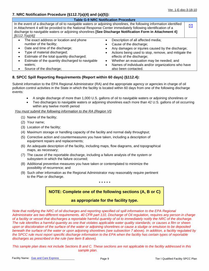
7. NRC Notification Procedure (§112.7(a)(4) and (a)(5)): Table G-9 NRC Notification Procedure
In the event of a discharge of oil to navigable waters or adjoining shorelines, the following information identified in Attachment 4 will be provided to the National Response Center immediately following identification of a discharge to navigable waters or adjoining shorelines [See Discharge Notification Form in Attachment 4]: [§112.7(a)(4)]
The exact address or location and phone number of the facility;
Date and time of the discharge; Type of material discharged; Estimate of the total quantity discharged; Estimate of the quantity discharged to navigable
waters; Source of the discharge;
Description of all affected media; Cause of the discharge; Any damages or injuries caused by the discharge; Actions being used to stop, remove, and mitigate the
effects of the discharge; Whether an evacuation may be needed; and Names of individuals and/or organizations who have
also been contacted.
8. SPCC Spill Reporting Requirements (Report within 60 days) (§112.4):
Submit information to the EPA Regional Administrator (RA) and the appropriate agency or agencies in charge of oil pollution control activities in the State in which the facility is located within 60 days from one of the following discharge events:
A single discharge of more than 1,000 U.S. gallons of oil to navigable waters or adjoining shorelines or Two discharges to navigable waters or adjoining shorelines each more than 42 U.S. gallons of oil occurring
within any twelve month period
* * * * *
Note that notifying the NRC of oil discharges and reporting specified oil spill information to the EPA Regional Administrator are two different requirements. 40 CFR part 110, Discharge of Oil regulation, requires any person in charge of a facility or vessel that discharges a reportable harmful quantity of oil to immediately notify the NRC of the discharge. The rule identifies a harmful quantity as one that violates applicable water quality standards; or causes a film or sheen upon or discoloration of the surface of the water or adjoining shorelines or cause a sludge or emulsion to be deposited beneath the surface of the water or upon adjoining shorelines (see subsection 7 above). In addition, a facility regulated by the SPCC rule must report specific discharge information to the EPA when the facility has certain types of reportable discharges as prescribed in the rule (see Item 8 above). This sample plan does not include Sections B and C. These sections are not applicable to the facility addressed in this
sample plan.
You must submit the following information to the RA (Region VI)
(1) Name of the facility;
(2) Your name;
(3) Location of the facility;
(4) Maximum storage or handling capacity of the facility and normal daily throughput;
(5) Corrective action and countermeasures you have taken, including a description of equipment repairs and replacements;
(6) An adequate description of the facility, including maps, flow diagrams, and topographical maps, as necessary;
(7) The cause of the reportable discharge, including a failure analysis of the system or subsystem in which the failure occurred;
(8) Additional preventive measures you have taken or contemplated to minimize the possibility of recurrence; and
(9) Such other information as the Regional Administrator may reasonably require pertinent to the Plan or discharge.
NOTE: Complete one of the following sections (A, B or C)
as appropriate for the facility type.

Ver. 1-E-doc-3-18-10
Page 10 Tier I Qualified Facility SPCC Plan Facility Name: Gas and Care Express
The owner or operator must meet the general rule requirements as well as requirements under this section. Note that not all provisions may be applicable to all owners/operators. For example, a facility may not maintain completely buried metallic storage tanks installed after January 10, 1974, and thus would not have to abide by requirements in §§112.8(c)(4) and 112.12(c)(4), listed below. In cases where a provision is not applicable, write “N/A”.
Table G-10 General Rule Requirements for Onshore Facilities N/A Drainage from diked storage areas is restrained by valves to prevent a discharge into the drainage system or facility effluent treatment system, except where facility systems are designed to control such discharge. Diked areas may be emptied by pumps or ejectors that must be manually activated after inspecting the condition of the accumulation to ensure no oil will be discharged. [§§112.8(b)(1) and 112.12(b)(1)]
Valves of manual, open-and-closed design are used for the drainage of diked areas. [§§112.8(b)(2) and 112.12(b)(2)]
The containers at the facility are compatible with materials stored and conditions of storage such as pressure and temperature. [§§112.8(c)(1) and 112.12(c)(1)]
Secondary containment for the bulk storage containers (including mobile/portable oil storage containers) holds the capacity of the largest container plus additional capacity to contain precipitation. Mobile or portable oil storage containers are positioned to prevent a discharge as described in §112.1(b). [§112.6(a)(3)(ii)]
If uncontaminated rainwater from diked areas drains into a storm drain or open watercourse the following procedures will be implemented at the facility: [§§112.8(c)(3) and 112.12(c)(3)]
Bypass valve is normally sealed closed Retained rainwater is inspected to ensure that its presence will not cause a discharge to
navigable waters or adjoining shorelines
Bypass valve is opened and resealed under responsible supervision
Adequate records of drainage are kept [See Dike Drainage Log in Attachment 3.3] For completely buried metallic tanks installed on or after January 10, 1974 at this facility [§§112.8(c)(4) and 112.12(c)(4)]:
Tanks have corrosion protection with coatings or cathodic protection compatible with local soil conditions.
Regular leak testing is conducted. For partially buried or bunkered metallic tanks [§112.8(c)(5) and §112.12(c)(5)]:
Tanks have corrosion protection with coatings or cathodic protection compatible with local soil conditions.
Each aboveground bulk container is tested or inspected for integrity on a regular schedule and whenever material repairs are made. Scope and frequency of the inspections and inspector qualifications are in accordance with industry standards. Container supports and foundations are regularly inspected. [See Inspection Log and Schedule and Bulk Storage Container Inspection Schedule in Attachments 3.1 and 3.2] [§112.8(c)(6) and §112.12(c)(6)(i)]
Outsides of bulk storage containers are frequently inspected for signs of deterioration, discharges, or accumulation of oil inside diked areas. [See Inspection Log and Schedule in Attachment 3.1] [§§112.8(c)(6) and 112.12(c)(6)]
For bulk storage containers that are subject to 21 CFR part 110 which are shop-fabricated, constructed of austenitic stainless steel, elevated and have no external insulation, formal visual inspection is conducted on a regular schedule. Appropriate qualifications for personnel performing tests and inspections are documented. [See Inspection Log and Schedule and Bulk Storage Container Inspection Schedule in Attachments 3.1 and 3.2] [§112.12(c)(6)(ii)]
A. Onshore Facilities (excluding production) (§§112.8(b) through (d), 112.12(b) through (d)):

Ver. 1-E-doc-3-18-10
Page 11 Tier I Qualified Facility SPCC Plan Facility Name: Gas and Care Express
Table G-10 General Rule Requirements for Onshore Facilities N/A Each container is provided with a system or documented procedure to prevent overfills for the container. Describe: Tank truck gasoline*, heating oil, and kerosene delivery procedures: 1) Manually gauge receiving tank to confirm liquid level in tank and quantity to be delivered to prevent tank overfill;
reconcile with inventory records and ATG, as applicable. Tanks will not be filled beyond 90% of their capacity. 2) Set parking brake and use chock blocks to prevent movement; inspect fittings and fueling hose for damage
before starting fuel transfer operation. The fuel delivery person makes all hook-ups. 3) Place drip pans under valve-hose fitting connections. 4) The person responsible for monitoring the delivery will remain attentive and observe the entire fuel delivery, be
prepared to stop the flow of fuel from the truck to the tank at any time, and respond to any unusual condition, leak, or spill which may occur during delivery. During heating oil and kerosene unloading, monitor the tank vent whistle on the heating oil tank and the liquid high-level alarm on the kerosene tank prior to initiating and during transfer. For delivery to the fuel oil tank, shutdown delivery if the vent whistle cannot be heard or the vent whistle stops sounding. For delivery to the kerosene tank, shutdown delivery when high-level alarm goes off. Secure all valves on tank truck before truck departure and inspect for leakage.
5) Following complete delivery, the fuel delivery person is responsible for disconnecting all hook-ups. 6) Record accurate readings for product and water in tank after fuel delivery, verify the amount of fuel received and
make sure fill ports are properly secured. 7) If an oil spill occurs, the spill kit will be used to contain the spill. The main spill kit is located in the gasoline sales
and customer service area. The maximum spill that would occur during an overfill while unloading gasoline is estimated at 20 gallons (a 4-inch truck fuel delivery hose, 30 feet in length, holds about 20 gallons). The maximum heating oil and kerosene unload rate is 25 gallons per minute (gpm) or 0.4 gallons per second (gps); the expected maximum amount to be spilled in an overfill incident during heating oil or kerosene unloading is about 3 gallons (0.4 gps x 8 seconds maximum to shutdown fuel transfer pump).
Gasoline dispenser customer fueling procedures: 1) Before dispenser filling, shutoff engine and cell phone. 2) Do not top off tank after automatic shut-off. 3) If an oil spill occurs, the spill kit will be used to contain the spill. The maximum dispenser pumping rate is 10 gpm
or less than 0.2 gps. In the event of a dispenser equipment failure such as a filling hose rupture or a vehicle fuel tank overfill, the expected maximum amount to be spilled is about 2 gallons (0.2 gps x 10 seconds maximum to shutdown dispenser fuel delivery pump).
Kerosene dispenser fuel transfers: 1) Customers are prohibited from operating the kerosene dispenser, including transferring kerosene into their
containers; employees will transfer kerosene into only authorized containers. 2) Do not top off container when filling; shutoff and lock the dispenser pump after completing transfer. 3) If an oil spill occurs, the spill kit will be used to contain the spill. The maximum dispenser pumping rate is 5 gpm
or less than 0.1 gps. In the event of a dispenser equipment failure such as a filling hose rupture or a container overfill, the expected maximum amount to be spilled is less than 0.5 gallon (0.1 gps x 5 seconds maximum to shutdown dispenser fuel delivery pump).
Transfers into waste oil AST: Gauge AST (manually or via visual gauge) to confirm liquid level in tank to prevent tank overfill. Transfers into waste oil tote: Transfer all waste oil into the tote fill port using a funnel. If an oil spill occurs, the spill kit in the shop will be used to contain the spill. Transfers into oil dispensing system drums: Confirm liquid level in drum glass sight gauge before transferring oil product into drum from supplier’s tote and monitor sight gauge during filling to prevent drum overfill; a drum will not be filled beyond 55 gallons. The maximum transfer rate of the supplier’s pump is 7.5 gpm or 0.1 gps. In the event of an overfill incident during the transfer, the expected maximum amount to be spilled is 0.5 gallons (0.1 gps maximum transfer rate x 5 seconds maximum to shutdown transfer pump). * For more information on operating and maintaining completely buried storage tanks, including safe practices, see www.epa.gov/oust/pubs/ommanual.htm
Liquid level sensing devices are regularly tested to ensure proper operation [See Inspection Log and Schedule in Attachment 3.1]. [§112.6(a)(3)(iii)]
Visible discharges which result in a loss of oil from the container, including but not limited to seams, gaskets, piping, pumps, valves, rivets, and bolts are promptly corrected and oil in diked areas is promptly removed. [§§112.8(c)(10) and 112.12(c)(10)]
Aboveground valves, piping, and appurtenances such as flange joints, expansion joints, valve glands and bodies, catch pans, pipeline supports, locking of valves, and metal surfaces are inspected regularly. [See Inspection Log and Schedule in Attachment 3.1] [§§112.8(d)(4) and 112.12(d)(4)]
Integrity and leak testing are conducted on buried piping at the time of installation, modification, construction, relocation, or replacement. [See Inspection Log and Schedule in Attachment 3.1] [§§112.8(d)(4) and 112.12(d)(4)]

Ver. 1-E-doc-3-18-10
Page 12 Tier I Qualified Facility SPCC Plan Facility Name: Gas and Care Express
ATTACHMENT 1 – Five Year Review and Technical Amendment Logs
By signing below, I am certifying that I have completed a review and evaluation of the SPCC Plan for this facility, and will/will not amend this Plan as a result.
An owner or operator must review and evaluate the SPCC Plan at least once every five years from the signature date of the Plan. A review of the Plan must also be completed whenever there is a change in the facility which affects the potential for a discharge of oil. In addition, the owner or operator has to amend the Plan within six months of review to include more effective prevention and control technology if the technology has been field-proven at the time of the review and will significantly reduce the likelihood of a discharge to navigable waters or adjoining shorelines. The owner or operator must implement any Plan amendment resulting from the review as soon as possible, but no longer than six months after the amendment.
Table G-13 Review and Evaluation of SPCC Plan for Facility Review Date Plan Amendment Name and signature of person authorized to review this
Plan Will Amend Will Not Amend
ATTACHMENT 1.1 – Five Year Review Log

Ver. 1-E-doc-3-18-10
Page 13 Tier I Qualified Facility SPCC Plan Facility Name: Gas and Care Express
ATTACHMENT 1.2 – Technical Amendment Log
Any technical amendments to this Plan will be re-certified in accordance with Section I of this Plan template.
Table G-15 Description and Certification of Technical Amendments Review Date
Description of Technical Amendment Name and signature of person certifying this technical amendment

Ver. 1-E-doc-3-18-10
Page 14 Tier I Qualified Facility SPCC Plan Facility Name: Gas and Care Express
An oil spill contingency plan and written commitment of resources is required for:
Flowlines and intra-facility gathering lines at oil production facilities; and
Qualified oil-filled operational equipment which has no secondary containment. NOT APPLICABLE
The SPCC Guidance for Regional Inspectors, EPA 550-B-05-001 provides further details on the use of the oil spill contingency plan to meet specific regulatory requirements and options.
An oil spill contingency plan meeting the provisions of 40 CFR part 109, as described below, and a written commitment of manpower, equipment and materials required to expeditiously control and remove any quantity of oil discharged that may be harmful is attached to this Plan.
Complete the checklist below to verify that the necessary operations outlined in 40 CFR part 109 - Criteria for State, Local and Regional Oil Removal Contingency Plans - have been included.
Table G-15 Checklist of Development and Implementation Criteria for State, Local and Regional Oil Removal Contingency Plans (§109.5)a
(a) Definition of the authorities, responsibilities and duties of all persons, organizations or agencies which are to be involved in planning or directing oil removal operations.
(b) Establishment of notification procedures for the purpose of early detection and timely notification of an oil discharge including:
(1) The identification of critical water use areas to facilitate the reporting of and response to oil discharges. (2) A current list of names, telephone numbers and addresses of the responsible persons (with alternates)
and organizations to be notified when an oil discharge is discovered.
(3) Provisions for access to a reliable communications system for timely notification of an oil discharge, and the capability of interconnection with the communications systems established under related oil removal contingency plans, particularly State and National plans (e.g., NCP).
(4) An established, prearranged procedure for requesting assistance during a major disaster or when the situation exceeds the response capability of the State, local or regional authority.
(c) Provisions to assure that full resource capability is known and can be committed during an oil discharge situation including:
(1) The identification and inventory of applicable equipment, materials and supplies which are available locally and regionally.
(2) An estimate of the equipment, materials and supplies which would be required to remove the maximum oil discharge to be anticipated.
(3) Development of agreements and arrangements in advance of an oil discharge for the acquisition of equipment, materials and supplies to be used in responding to such a discharge.
(d) Provisions for well defined and specific actions to be taken after discovery and notification of an oil discharge including:
(1) Specification of an oil discharge response operating team consisting of trained, prepared and available operating personnel.
(2) Predesignation of a properly qualified oil discharge response coordinator who is charged with the responsibility and delegated commensurate authority for directing and coordinating response operations and who knows how to request assistance from Federal authorities operating under existing national and regional contingency plans.
(3) A preplanned location for an oil discharge response operations center and a reliable communications system for directing the coordinated overall response operations.
(4) Provisions for varying degrees of response effort depending on the severity of the oil discharge.
(5) Specification of the order of priority in which the various water uses are to be protected where more than one water use may be adversely affected as a result of an oil discharge and where response operations may not be adequate to protect all uses.
(6) Specific and well defined procedures to facilitate recovery of damages and enforcement measures as provided for by State and local statutes and ordinances.
a The contingency plan must be consistent with all applicable state and local plans, Area Contingency Plans, and the National Contingency Plan (NCP)
ATTACHMENT 2 – Oil Spill Contingency Plan and Checklist;

Ver. 1-E-doc-3-18-10
Page 15 Tier I Qualified Facility SPCC Plan
ATTACHMENT 3 – Inspections, Dike Drainage and Personnel Training Logs
Table G-16 Inspection Log and Schedule This log is intended to document compliance with §§112.6(a)(3)(iii), 112.8(c)(6), 112.8(d)(4), 112.9(b)(2), 112.9(c)(3), 112.9(d)(1), 112.9(d)(4), 112.12.(c)(6), and
112.12(d)(4), as applicable.
Date of Inspection
Container / Piping / Equipment
Describe Scope (or cite Industry Standard)
Observations Name/ Signature of Inspector
Records maintained separately a
ASTs 1,500-gal. waste oil
tank #1 275-gal. heating oil
tank #2 500-gal. kerosene
tank #3 65-gal. drums #1 to
#12
Monthly and annual visual inspections as all containers meet Category 1 criteria (STI SP001, Standard for the Inspection of Aboveground Storage Tanks)
Secondary containment dike
Weekly visual inspections and after heavy rainfall
Liquid level gauges and high-level alarms
Gauges- Annual inspections and calibration following manufacturer’s procedures
Vent whistle- test with each delivery and at least annual inspections following manufacturer’s procedures
High-level alarm- monthly inspections and annual functional test following manufacturer’s procedures
Dispensers Daily visual inspections of the dispenser sumps, fill nozzles, hoses, and fittings (manufacturer instructions)
Spill kits Monthly visual inspections and equipment/supply inventory
a Indicate in the table above if records of facility inspections are maintained separately at this facility. The scope of STI SP001 Standard for the Inspection of Aboveground Storage Tanks by the Steel Tank Institute (STI) includes the inspection and testing of aboveground shop-fabricated tanks, small field-erected tanks, portable containers, and associated secondary containment. The standard is copyrighted. However, the periodic tank inspection checklists in Appendix C of the standard are not copyrighted. These checklists are attached to this example template SPCC Plan. Utilization of the checklists alone does not constitute compliance with the standard. The standard is available from STI at the following web address: https://www.steeltank.com/Publications/PublicationsIndex/tabid/108/Default.aspx.
Facility Name: Gas and Care Express Facility Name:
ATTACHMENT 3.1 – Inspection Log and Schedule

Ver. 1-E-doc-3-18-10
Page 16 Tier I Qualified Facility SPCC Plan
To comply with integrity inspection requirement for bulk storage containers, inspect/test each shop-built aboveground bulk storage container on a regular schedule in accordance with a recognized container inspection standard based on the minimum requirements in the following table.
Table G-17 Bulk Storage Container Inspection Schedule Container Size and Design Specification Inspection requirement
Portable containers (including drums, totes, and intermodal bulk containers (IBC)):
Visually inspect monthly for signs of deterioration, discharges or accumulation of oil inside containment pallets.
55 to 1,100 gallons with sized secondary containment: 65-gal. steel lube and other oil product drums #1 to #12 275-gal. heating oil AST #2 500-gal. kerosene AST #3
Visually inspect monthly for signs of deterioration, discharges or accumulation of oil inside bermed area plus any annual inspection elements per industry inspection standards
1,101 to 5,000 gallons with sized secondary containment and a means of leak detectiona:
1,500-gal. waste oil AST #1 1,101 to 5,000 gallons with sized secondary containment and no method of leak detectiona:
Visually inspect monthly for signs of deterioration, discharges or accumulation of oil inside diked areas, plus any annual inspection elements and other specific integrity tests that may be required per industry inspection standards
a Examples of leak detection include, but are not limited to, double-walled tanks and elevated containers where a leak can be visually identified. In this example, the Gas and Care Express owner has elected to use STI’s SP001, tank inspection and testing standard; this standard is an example of an industry inspection standard that can be used to conduct inspections and formal tank testing. Under this standard, inspection and integrity test requirements depend on the spill risk posed by the tank; tanks posing higher spill risks have more inspection and integrity test requirements. Take the example of a 1,500-gallon AST that rests on the ground within an earthen berm. As the tank bottom is in direct contact with the ground, it is not likely that a leak from the tank bottom would be seen. Note that a metal tank in direct contact with the ground soil is subject to corrosion. According to STI SP001, the earthen berm provides a method of spill control but not a method of continuous release detection due to the tank being in direct contact with the ground. This standard defines continuous release detection as a method that allows the facility operator to visually detect releases. Examples are double-wall or double-bottom ASTs with the space between the walls capable of being tested and monitored for releases. Other examples include ASTs that are raised above the ground with supports, grating or without or with release prevention barriers under the tank, such as liners, steel, and/or concrete. Consequently, the 1,500-gallon tank in this note example poses a higher spill risk than a 1,500-gallon tank elevated on supports in the berm. According to STI SP001, in addition to monthly and annual visual inspections in the standard, this example tank also requires formal external inspections by a certified tank inspector and leak tests by the facility every 10 years.
Facility Name: Gas and Care Express
ATTACHMENT 3.2 – Bulk Storage Container Inspection Schedule – onshore facilities (excluding production):

Ver. 1-E-doc-3-18-10
Page 17 Tier I Qualified Facility SPCC Plan
2 Table G-18 Dike Drainage Log
Date
Bypass valve
sealed closed
Rainwater inspected to be sure no oil (or
sheen) is visible
Open bypass valve and reseal it following drainage
Drainage activity
supervised Observations Signature of Inspector
Facility Name: Gas and Care Express
ATTACHMENT 3.3 – Dike Drainage Log

Ver. 1-E-doc-3-18-10
Page 18 Tier I Qualified Facility SPCC Plan
2 Table G-19 Oil-Handling Personnel Training and Briefing Log
Date Description / Scope Attendees
Facility Name: Gas and Care Express
ATTACHMENT 3.4 – Oil-handling Personnel Training and Briefing Log

Ver. 1-E-doc-3-18-10
Page 19 Tier I Qualified Facility SPCC Plan
In the event of a discharge of oil to navigable waters or adjoining shorelines, the following information will be provided to the National Response Center [also see the notification information provided in Section 7 of the Plan]:
Table G-20 Information provided to the National Response Center in the Event of a Discharge Discharge/Discovery Date
Time
Facility Name
Facility Location (Address/Lat-Long/Section Township Range)
Name of reporting individual
Telephone #
Type of material discharged
Estimated total quantity discharged
Gallons/Barrels
Source of the discharge
Media affected Soil
Water (specify)
Other (specify)
Actions taken
Damage or injuries
No Yes (specify)
Evacuation needed? No Yes (specify)
Organizations and individuals contacted
National Response Center 800-424-8802 Time
Cleanup contractor (Specify) Time
Facility personnel (Specify) Time
State Agency (Specify) Time
Other (Specify) Time
Facility Name: Gas and Care Express