AUTO-PRODUCER CUBICLE 24kV
28
www.evaelektromekanik.com METAL ENCLOSED MODULAR SWITCHGEARS (MMMH) USER GUIDE AUTO-PRODUCER CUBICLE 24kV Assembly, Operating and Maintenance Instructions
Transcript of AUTO-PRODUCER CUBICLE 24kV
www.evaelektromekanik.com
MET
AL
ENCL
OSE
D M
OD
ULA
R SW
ITCH
GEA
RS
(MM
MH
) USE
R G
UID
E
AUTO-PRODUCER CUBICLE 24kVAssembly, Operating and Maintenance Instructions

EVA ELEKTROMEKANİK SAN. VE TİC. LTD. ŞTİ. DAĞYAKA MAH. 2008. CAD. NO:5 KAHRAMANKAZAN, ANKARA, TÜRKİYETel: +90 312 811 27 27 Fax: +90 312 811 27 28www.evaelektromekanik.com
All rights reserved. Any part of this catalogue can not be copied without the permission of the rightholder. It can only be copiedand augmented with the written permission of EVA ELEKTROMEKANİK SAN. VE TİC. LTD. ŞTİ.
Switching The Future...
CON
TEN
TS
1. GENERAL FEATURES 2
1.1 GENERAL SECTIONS 2
1.2 STANDARDS 2
1.3 CHARACTERISTIC FEATURES 3
2-LOADING - UNLOADING - TRANSPORTING 4
2.1 TRANSPORTING WITH FORKLIFT 4
2.2 TRANSPORTING OVER THE PIPE 4
2.3 TRANSPORTING BY LIFTING SLING 5
3 - INSTALLATION 5
3.1 - TOOLS LIST REQUIRED DURING INSTALLATION 5
3.2 - MATERIALS LIST SENT WITH THE CUBICLE 5
3.3 - CUBICLE’S PLACEMENT 6
3.4 - CONNECTING THE CUBICLES TO EACH OTHER 7
3.5 -MAIN BUSBARS CONNECTION 8
3.6 – EARTHING BUSBARS CONNECTION 9
3.7 - CONNECTING THE CUBICLES’ ARRAY TO THE MAIN GROUNDING SYSTEM OF THE FACILITY 9
3.8 –PASSAGES OF AUXILIARY SERVICE AND CONTROL CABLES FROM CUBICLE TO ANOTHER 10
3.9 - CONNECTION OF MV CABLES 11
3.10 - MATTERS TO BE CONSIDERED AGAINST INTERNAL ARC WHEN THE CUBICLE IS MOUNTED 11
4 - COMMISSIONING 12
4.1 - CHECKS TO BE PERFORMED BY THE BARE EYE 12
4.2 - MECHANICAL CHECKS 13
4.3 - SUPPLYING VOLTAGE TO THE MAIN BUSBAR AND REQUIRED CHECKS 13
4.4- OPERATING THE AUTO-PRODUCER CUBICLE 13
4.5- SHUTTING DOWN THE AUTO PRODUCER CUBICLE 16
5 - MAINTENANCE INSTRUCTIONS AND RECOMMENDATIONS FOR THE AIR INSULATED METAL ENCLOSED CUBICLES MMMH TYPE 18
5.1-MAIN BUSBAR COMPARTMENT 18
5.2-SF6 GAS INSULATED DISCONNECTORS AND SF6 GAS INSULATED LOAD BREAK SWITCHES 18
5.3 MV CIRCUIT BREAKERS 18
5.4 MV VOLTAGE TRANSFORMERS 23
5.5 MV CURRENT TRANSFORMERS 23
5.6 EARTHING DISCONNETORS 23
5.7 -MECHANISMS’ CONTROL 23
5.8 -RELAY AND METERING TOOLS 23
5.9 -EARTHING CIRCUIT 24
5.10-LV COMPARTMENT 24
5.11 MECHANICAL INTERLOCKING SYSTEM 24
5.12 AUXILIARY POWER SUPPLY 24
5.13 LIST OF TOOLS REQUIRED DURING MAINTENANCE AND INSTALLATION 24
6 - GUARANTEE TERMS 24
www.evaelektromekanik.com2
1- GENERAL FEATURES
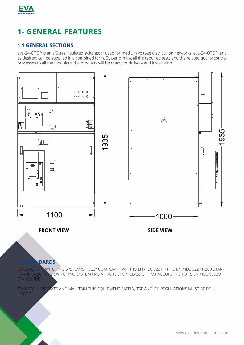
eva-24-OTOP is an sf6 gas insulated switchgear used for medium voltage distribution networks. eva-24-OTOP, and as desired, can be supplied in a combined form. By performing all the required tests and the related quality control processes to all the modulars, the products will be ready for delivery and installation.
1.1 GENERAL SECTIONS
FRONT VIEW SIDE VIEW
eva-24-OTOP SWITCHING SYSTEM IS FULLY COMPLIANT WITH TS EN / IEC 62271-1, TS EN / IEC 62271-200 STAN-DARDS. ALSO, THIS SWITCHING SYSTEM HAS A PROTECTION CLASS OF IP3X ACCORDING TO TS EN / IEC 60529 STANDARDS.
TO INSTALL, OPERATE AND MAINTAIN THIS EQUIPMENT SAFELY, TSE AND IEC REGULATIONS MUST BE FOL-LOWED.
1.2 STANDARDS
www.evaelektromekanik.com 3
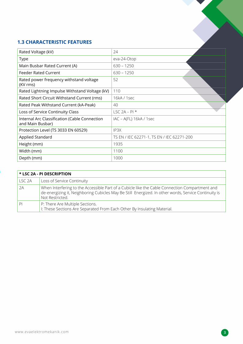
Rated Voltage (kV) 24
Type eva-24-Otop
Main Busbar Rated Current (A) 630 – 1250
Feeder Rated Current 630 – 1250
Rated power frequency withstand voltage (KV rms)
52
Rated Lightning Impulse Withstand Voltage (kV) 110
Rated Short Circuit Withstand Current (rms) 16kA / 1sec
Rated Peak Withstand Current (kA-Peak) 40
Loss of Service Continuity Class LSC 2A – PI *
Internal Arc Classification (Cable Connection and Main Busbar)
IAC – A(FL) 16kA / 1sec
Protection Level (TS 3033 EN 60529) IP3X
Applied Standard TS EN / IEC 62271-1, TS EN / IEC 62271-200
Height (mm) 1935
Width (mm) 1100
Depth (mm) 1000
1.3 CHARACTERISTIC FEATURES
* LSC 2A - PI DESCRIPTIONLSC 2A Loss of Service Continuity
2A When Interfering to the Accessible Part of a Cubicle like the Cable Connection Compartment and de-energizing it, Neighboring Cubicles May Be Still Energized. In other words, Service Continuity is Not Restricted.
PI P: There Are Multiple Sections.I: These Sections Are Separated From Each Other By Insulating Material.
www.evaelektromekanik.com4
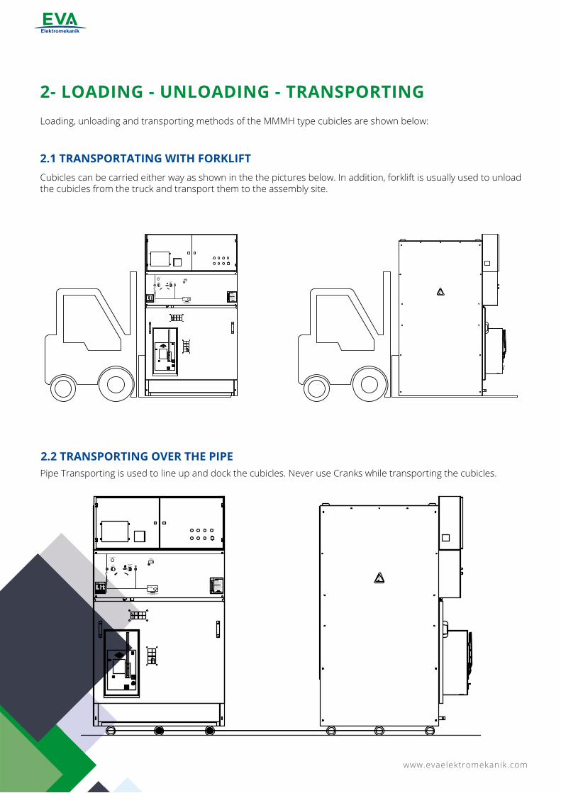
2- LOADING - UNLOADING - TRANSPORTINGLoading, unloading and transporting methods of the MMMH type cubicles are shown below:
Cubicles can be carried either way as shown in the the pictures below. In addition, forklift is usually used to unload the cubicles from the truck and transport them to the assembly site.
Pipe Transporting is used to line up and dock the cubicles. Never use Cranks while transporting the cubicles.
2.1 TRANSPORTATING WITH FORKLIFT
2.2 TRANSPORTING OVER THE PIPE
www.evaelektromekanik.com 5
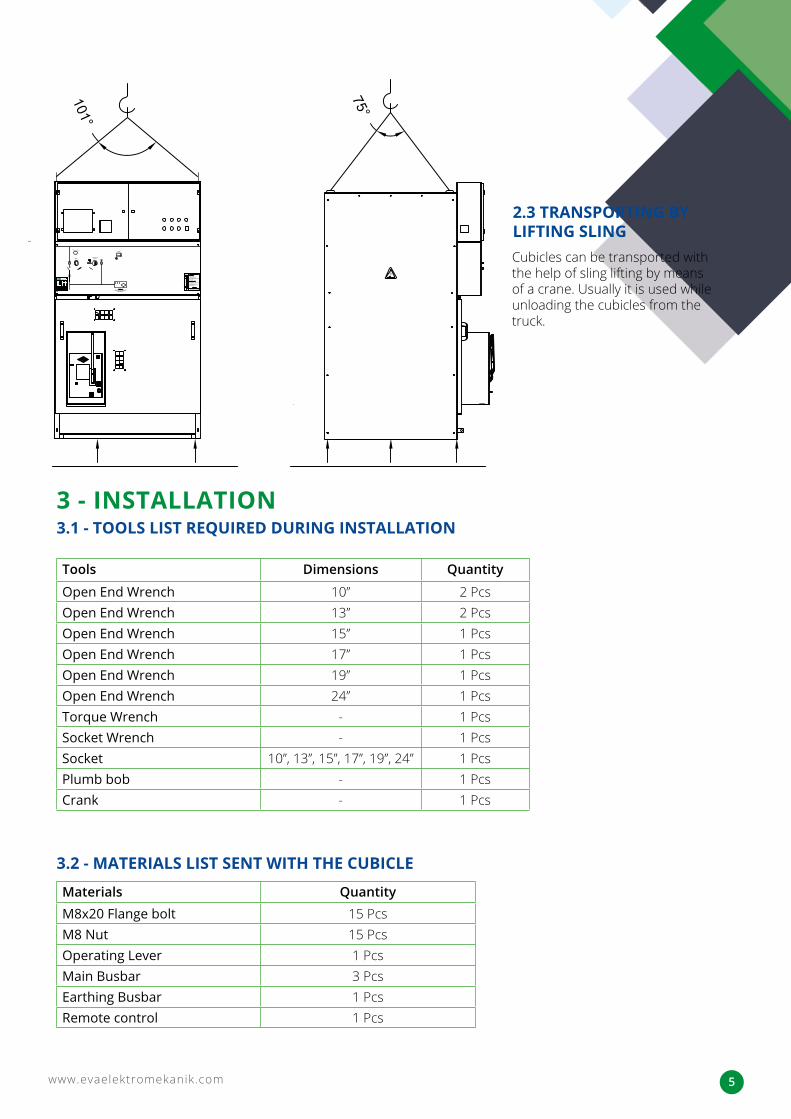
Cubicles can be transported with the help of sling lifting by means of a crane. Usually it is used while unloading the cubicles from the truck.
2.3 TRANSPORTING BY LIFTING SLING
3 - INSTALLATION3.1 - TOOLS LIST REQUIRED DURING INSTALLATION
3.2 - MATERIALS LIST SENT WITH THE CUBICLE
Tools Dimensions Quantity
Open End Wrench 10’’ 2 PcsOpen End Wrench 13’’ 2 PcsOpen End Wrench 15’’ 1 PcsOpen End Wrench 17’’ 1 PcsOpen End Wrench 19’’ 1 PcsOpen End Wrench 24’’ 1 PcsTorque Wrench - 1 PcsSocket Wrench - 1 PcsSocket 10’’, 13’’, 15’’, 17’’, 19’’, 24’’ 1 PcsPlumb bob - 1 PcsCrank - 1 Pcs
Materials QuantityM8x20 Flange bolt 15 PcsM8 Nut 15 PcsOperating Lever 1 PcsMain Busbar 3 PcsEarthing Busbar 1 PcsRemote control 1 Pcs
www.evaelektromekanik.com6
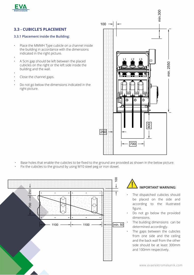
• Place the MMMH Type cubicle on a channel inside the building in accordance with the dimensions indicated in the right picture.
• • A 5cm gap should be left between the placed
cubicles on the right or the left side inside the building and the wall.
• • Close the channel gaps.• • Do not go below the dimensions indicated in the
right picture.
3.3.1 Placement inside the Building:
3.3 - CUBICLE’S PLACEMENT
• Base holes that enable the cubicles to be fixed to the ground are provided as shown in the below picture.• Fix the cubicles to the ground by using M10 steel peg or iron dowel.
• The dispatched cubicles should be placed on the side and according to the illustrated figure.
• Do not go below the provided dimensions.
• The building dimensions can be determined accordingly.
• The gaps between the cubicles from one side and the ceiling and the back wall from the other side should be at least 300mm and 100mm respectively.
IMPORTANT WARNING:
www.evaelektromekanik.com 7
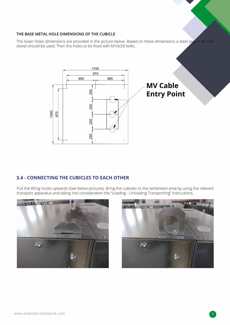
The lower holes dimensions are provided in the picture below. Based on these dimensions a steel peg or an iron dowel should be used. Then the holes to be fixed with M10x50 bolts.
THE BASE METAL HOLE DIMENSIONS OF THE CUBICLE
MV Cable Entry Point
3.4 - CONNECTING THE CUBICLES TO EACH OTHER
Pull the lifting hooks upwards (See below pictures). Bring the cubicles to the settlement area by using the relevant transport apparatus and taking into consideration the “Loading - Unloading Transporting” instructions.
www.evaelektromekanik.com8
1
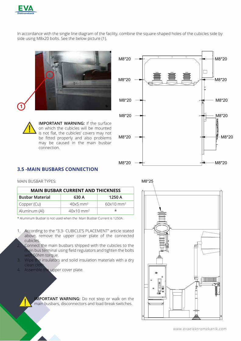
In accordance with the single line diagram of the facility, combine the square-shaped holes of the cubicles side by side using M8x20 bolts. See the below picture (1).
1. According to the “3.3- CUBICLE’S PLACEMENT” article stated above, remove the upper cover plate of the connected cubicles.
2. Connect the main busbars shipped with the cubicles to the main bus terminal using field regulators and tighten the bolts with 50Nm torque.
3. Wipe the insulators and solid insulation materials with a dry clean cloth.
4. Assemble the upper cover plate.
3.5 -MAIN BUSBARS CONNECTION
MAIN BUSBAR TYPES:
* Aluminum Busbar is not used when the Main Busbar Current is 1250A .
MAIN BUSBAR CURRENT AND THICKNESSBusbar Material 630 A 1250 A
Copper (Cu) 40x5 mm2 60x10 mm2
Aluminum (Al) 40x10 mm2 *
IMPORTANT WARNING: If the surface on which the cubicles will be mounted is not flat, the cubicles’ covers may not be fitted properly and also problems may be caused in the main busbar connection.
IMPORTANT WARNING: Do not step or walk on the main busbars, disconnectors and load break switches.
www.evaelektromekanik.com 9
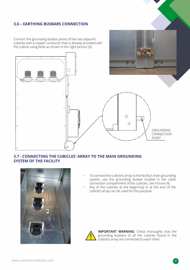
Connect the grounding busbar points of the two adjacent cubicles with a copper conductor that is already provided with the cubicle using bolts as shown in the right picture (3).
GROUNDING CONNECTION POINT
• To connect the cubicle’s array to the facility’s main grounding system, use the grounding busbar located in the cable connection compartment of the cubicles. See Picture (4).
• Any of the cubicles at the beginning or at the end of the cubicle’s array can be used for this purpose.
3.6 – EARTHING BUSBARS CONNECTION
3.7 - CONNECTING THE CUBICLES′ ARRAY TO THE MAIN GROUNDING SYSTEM OF THE FACILITY
IMPORTANT WARNING: Check thoroughly that the grounding busbars of all the cubicles found in the cubicle’s array are connected to each other.
www.evaelektromekanik.com10
3.8 –PASSAGES OF AUXILIARY SERVICE AND CONTROL CABLES FROM CUBICLE TO ANOTHER
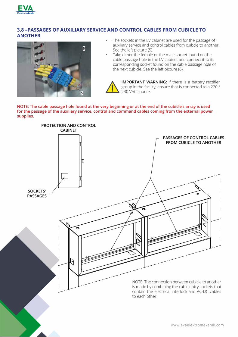
• The sockets in the LV cabinet are used for the passage of auxiliary service and control cables from cuibcle to another. See the left picture (5).
• Take either the female or the male socket found on the cable passage hole in the LV cabinet and connect it to its corresponding socket found on the cable passage hole of the next cubicle. See the left picture (6).
NOTE: The connection between cubicle to another is made by combining the cable entry sockets that contain the electrical interlock and AC-DC cables to each other.
NOTE: The cable passage hole found at the very beginning or at the end of the cubicle’s array is used for the passage of the auxiliary service, control and command cables coming from the external power supplies.
IMPORTANT WARNING: If there is a battery rectifier group in the facility, ensure that is connected to a 220 / 230 VAC source.
PROTECTION AND CONTROL CABINET
PASSAGES OF CONTROL CABLES FROM CUBICLE TO ANOTHER
SOCKETS’ PASSAGES
www.evaelektromekanik.com 11
7
3.9 - CONNECTION OF MV CABLES
3.10 - MATTERS TO BE CONSIDERED AGAINST INTERNAL ARC WHEN THE CUBICLE IS MOUNTED
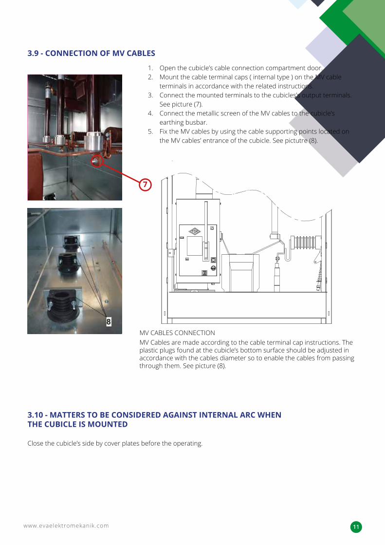
MV CABLES CONNECTIONMV Cables are made according to the cable terminal cap instructions. The plastic plugs found at the cubicle’s bottom surface should be adjusted in accordance with the cables diameter so to enable the cables from passing through them. See picture (8).
1. Open the cubicle’s cable connection compartment door.2. Mount the cable terminal caps ( internal type ) on the MV cable
terminals in accordance with the related instructions.3. Connect the mounted terminals to the cubicles’s output terminals.
See picture (7).4. Connect the metallic screen of the MV cables to the cubicle’s
earthing busbar.5. Fix the MV cables by using the cable supporting points located on
the MV cables’ entrance of the cubicle. See pictutre (8).
Close the cubicle’s side by cover plates before the operating.
www.evaelektromekanik.com12
4.1 - CHECKS TO BE PERFORMED BY THE BARE EYE (Checks to be Performed While the Main Busbar is De-energized)
IMPORTANT WARNING: Never connect the MV cables connected to the output terminal in a way that will force the output terminals to pull down.
4 - COMMISSIONINGIf a cubicle array will be formed by arranging various types of MMMH cubicles side by side and the commissioning wil be performed for the first time, it is recommended by our company to apply the following procedure:
1. Check whether the connections of the cubicles’ main busbar are connected along with the disconnector or the load break switch or not and tighten the loose bolts and nuts if required. While checking the connectivity, be careful from damaging the bushings of the disconnector or the load break switch. Never step or walk on the busbar, disconnector or the load breaker switch.
2. To determine that there are no cracks, fractures, carbonization marks or any defects on the bushings’ body, wipe it with a dry cloth.
3. Check the conductor connections in the switchgear for the breaker, load breaker, disconnector, current transformer, etc. by opening the cable connection compartment door of the cubicles and then tighten the loose bolts with 15-20Nm Torque if required. Clean the insulators and solid insulation materials with a dry cloth.
4. Check if there is any unusual object inside the cubicle and take it out.5. Check that there is at least 100 mm gap between the cubicles’ back and the building’s wall and that there is no
objects in between.6. Check whether the side cover plates used against the internal arc are fixed, if not fix them so. 7. If there is a battery rectifier group in the facility, ensure that is connected to a 220 / 230 VAC source. 8. Ensure the grounding system of the cubicles by checking the grounding busbars of the cubicles’ array
which must be properly and tightly connected to each other. Also, ensure the cubicles’ grounding system by checking the earthing busbar of the first or the last cubicle which must be connected to the external earthing system by an earthing conductor.
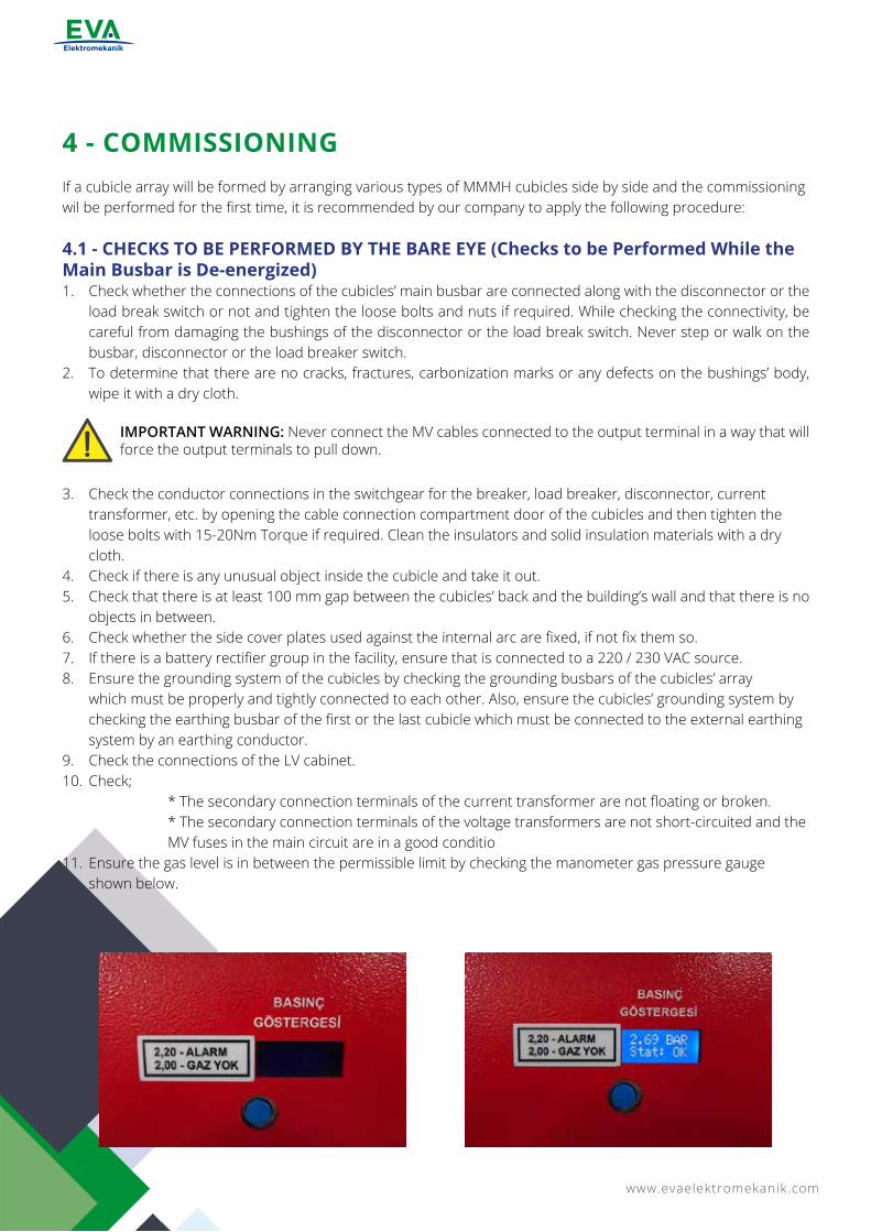
9. Check the connections of the LV cabinet.10. Check; * The secondary connection terminals of the current transformer are not floating or broken. * The secondary connection terminals of the voltage transformers are not short-circuited and the MV fuses in the main circuit are in a good conditio 11. Ensure the gas level is in between the permissible limit by checking the manometer gas pressure gauge
shown below.
www.evaelektromekanik.com 13
4.2 - MECHANICAL CHECKS (Checks to be Made in This Section Should Be Performed While the Main Busbar is De-energized.)1. Perform “Commissioning”, “De-commissioning” and the “Accessibility to Cable Connection Compartment” for
each cubicle in accordance with the operating instructions sticked on them. During that, check the mechanical interlocks are operating properly and no problems are occured.
2. Check the equipment’s control mechanisms are performing properly and the TRIPPING-CLOSING indicator positions show the right positions.
3. Please contact EVA ELEKTROMEKANİK on (0090 312 811 2727) if any problem is encountered during the above points.
4.3 - SUPPLYING VOLTAGE TO THE MAIN BUSBAR AND REQUIRED CHECKS
1. Switch on all the switching elements found on the cubicles’ array.2. By Switching off the switching elements of the incoming cubicle, energize the main busbar and wait for 90 to
120 minutes.3. Ensure that the voltage indicators lamps of the incoming cubicle are off. 4. If no problems were observed then energize the cubicles one by one as stated below.5. After energizing the cubicle’s array, check whether if there is unusual noise or not.
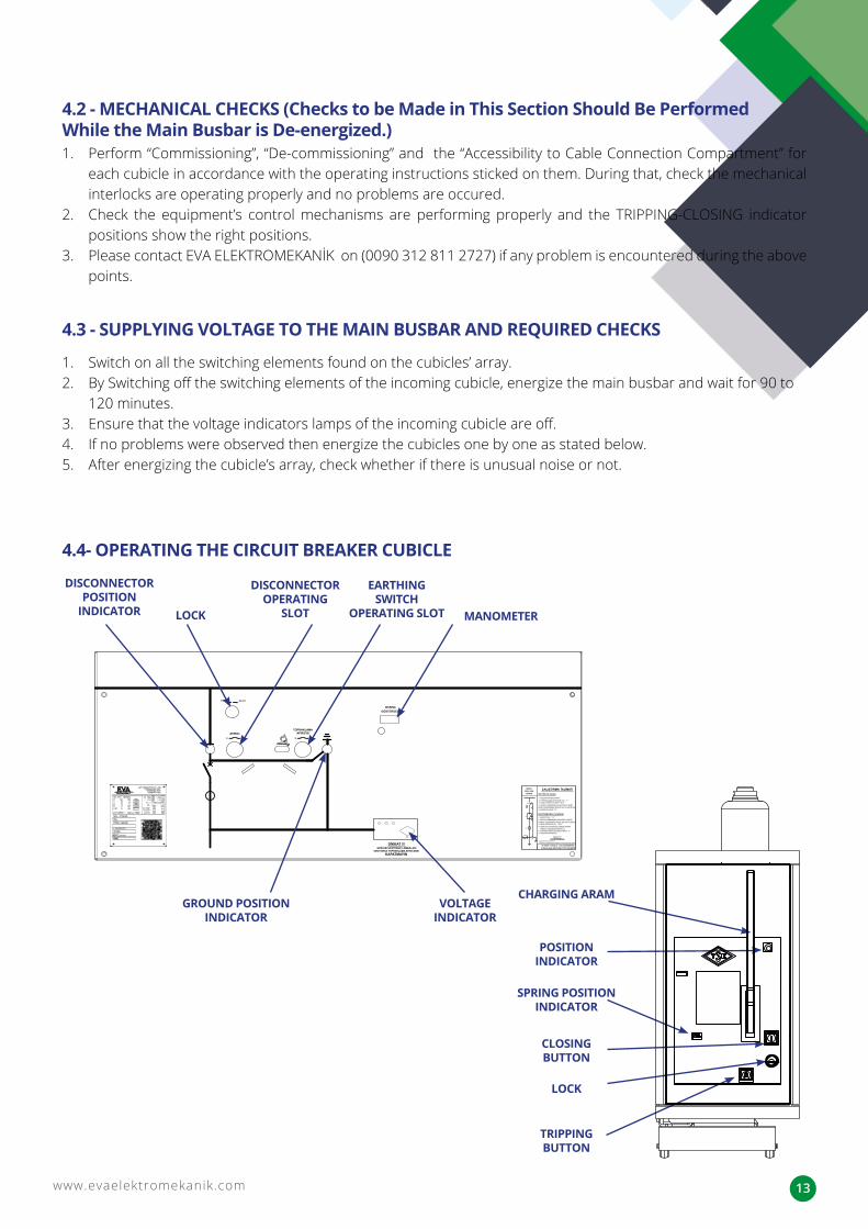
4.4- OPERATING THE CIRCUIT BREAKER CUBICLE
DISCONNECTOR POSITION
INDICATOR MANOMETER
DISCONNECTOR OPERATING
SLOTLOCK
EARTHING SWITCH
OPERATING SLOT
VOLTAGE INDICATOR
TRIPPINGBUTTON
CHARGING ARAM
POSITION INDICATOR
SPRING POSITION INDICATOR
CLOSINGBUTTON
LOCK
GROUND POSITION INDICATOR

www.evaelektromekanik.com14
2. Put the Operating Lever into the Earthing Switch Operating Slot and Switch On the Earthing Switch by turning it clockwise.
The ground will come into the
position shown in the figure.
The disconnector will come into
the position shown in the figure.
3. Put the Operating Lever into the Disconnector Opearting Slot and Switch it Off by turning it counterclockwise.
Operating Lever
1. If the Cable Connection Compartment Door of the Circuit Breaker Cubicle is Open, Close it.
www.evaelektromekanik.com 15
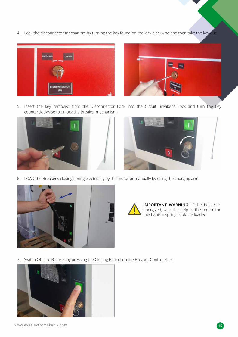
4. Lock the disconnector mechanism by turning the key found on the lock clockwise and then take the key out.
5. Insert the key removed from the Disconnector Lock into the Circuit Breaker’s Lock and turn the key counterclockwise to unlock the Breaker mechanism.
6. LOAD the Breaker’s closing spring electrically by the motor or manually by using the charging arm.
7. Switch Off the Breaker by pressing the Closing Button on the Breaker Control Panel.
IMPORTANT WARNING: If the beaker is energized, with the help of the motor the mechanism spring could be loaded.
www.evaelektromekanik.com16
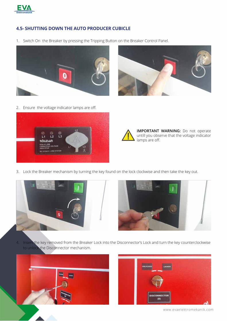
4.5- SHUTTING DOWN THE AUTO PRODUCER CUBICLE
1. Switch On the Breaker by pressing the Tripping Button on the Breaker Control Panel.
2. Ensure the voltage indicator lamps are off.
3. Lock the Breaker mechanism by turning the key found on the lock clockwise and then take the key out.
4. Insert the key removed from the Breaker Lock into the Disconnector’s Lock and turn the key counterclockwise to unlock the Disconnector mechanism.
IMPORTANT WARNING: Do not operate untill you observe that the voltage indicator lamps are off.
www.evaelektromekanik.com 17
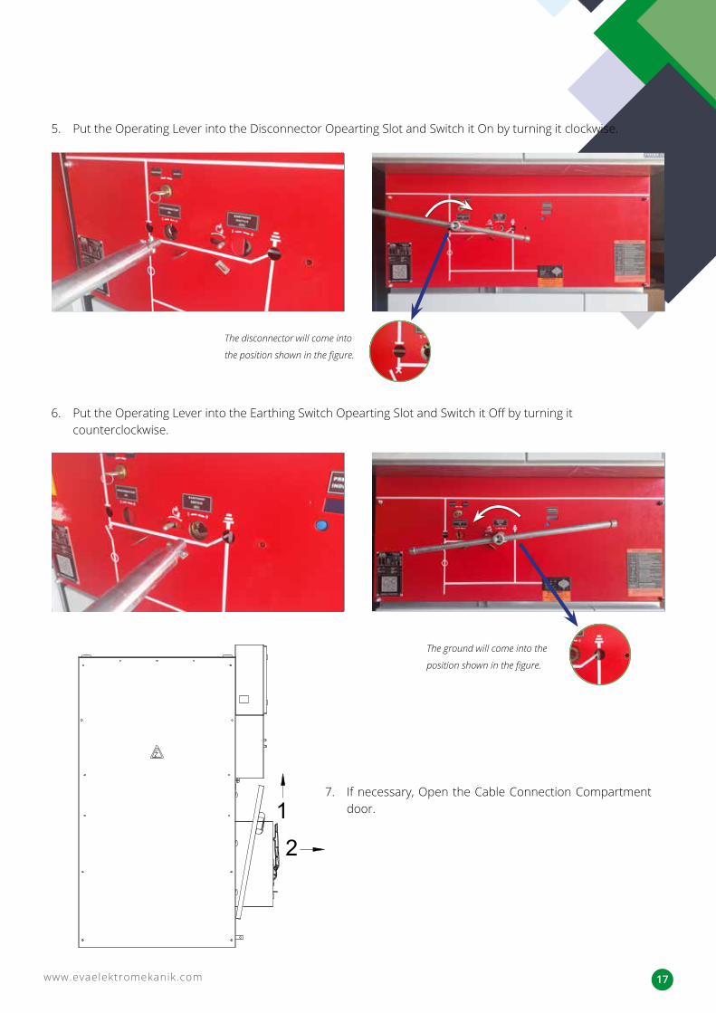
5. Put the Operating Lever into the Disconnector Opearting Slot and Switch it On by turning it clockwise.
6. Put the Operating Lever into the Earthing Switch Opearting Slot and Switch it Off by turning it counterclockwise.
The disconnector will come into
the position shown in the figure.
7. If necessary, Open the Cable Connection Compartment door.
The ground will come into the
position shown in the figure.
www.evaelektromekanik.com18
5.3- MV CIRCUIT BREAKERS
5.1-MAIN BUSBAR COMPARTMENT
5.2-SF6 GAS INSULATED DISCONNECTORS AND SF6 GAS INSULATED LOAD BREAK SWITCHES
1. Check whether the connections of the cubicles’ main busbar are connected along with the disconnector or the load break switch or not and tighten the loose bolts and nuts if required. While checking the connectivity, be careful from damaging the bushings of the disconnector or the break switch. Never step or walk on the busbar and the disconnector or the load breaker switch.
2. To determine that there are no cracks, fractures, carbonization marks or any defects on the bushings’ body, wipe it with a dry cloth.
1. Open the Cable Connection Compartment Door. If the door cannot be opened, check whether the door opening method is applied correctly or not.
2. Check the conductors connections between the main circuit and the equipment and tighten the loose bolts and nuts with 15-20Nm Torque if required. While checking the connectivity, be careful from damaging the bushings of the disconnector or the load break switch.
1. Open the Cable Connection Compartment Door. If the door cannot be opened, check whether the door opening method is applied correctly or not.
2. Check the conductors connections between the main circuit and the equipment and tighten the loose bolts and nuts with 15-20Nm Torque if required. While checking the connectivity, be careful from damaging the circuit breaker, the bushings of the disconnector or the terminals.
3. To determine that there are no cracks, fractures, carbonization marks or any defects on the bushings’ body, wipe it with a dry cloth.
4. Follow the manufacturer’s instructions.
In order to find the cables connection points and the equipment lower terminals, open the Cable Connection Compartment Door.
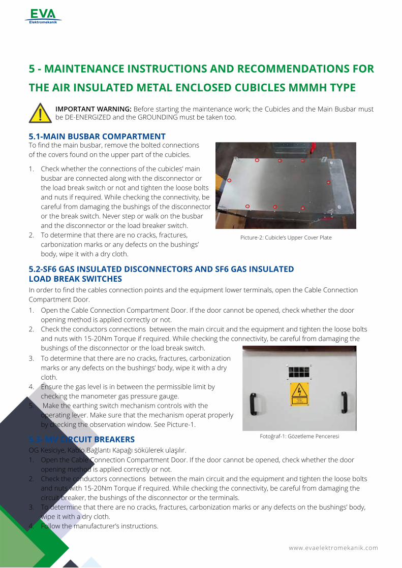
Picture-2: Cubicle’s Upper Cover Plate
OG Kesiciye, Kablo Bağlantı Kapağı sökülerek ulaşılır.
To find the main busbar, remove the bolted connections of the covers found on the upper part of the cubicles.
IMPORTANT WARNING: Before starting the maintenance work; the Cubicles and the Main Busbar must be DE-ENERGIZED and the GROUNDING must be taken too.
5 - MAINTENANCE INSTRUCTIONS AND RECOMMENDATIONS FOR
THE AIR INSULATED METAL ENCLOSED CUBICLES MMMH TYPE
Fotoğraf-1: Gözetleme Penceresi
3. To determine that there are no cracks, fractures, carbonization marks or any defects on the bushings’ body, wipe it with a dry cloth.
4. Ensure the gas level is in between the permissible limit by checking the manometer gas pressure gauge.
5. Make the earthing switch mechanism controls with the operating lever. Make sure that the mechanism operat properly by checking the observation window. See Picture-1.
www.evaelektromekanik.com 19
CIRCUIT BREAKER MAINTENANCE:
PREVENTIVE MAINTENANCE TABLE
Safety information:All operations described below must be carried out in accordance with safety standards and under an authorized supervision. In order to access the circuit breaker parts follow the below steps:1. Open the breaker.2. Disconnect the power from the terminals and / or the plug socket system (optional).3. To discharge the energy in the closing spring found at the breaker, turn it off and on by using the closing and
tripping buttons.4. Take the key after locking the mechanical lock.5. Remove the breaker protective cover.6. Protect the breaker terminals from external impacts.This breaker is designed to operate for 10,000 operations or 20 years of use under normal operating conditions according to IEC 62271-1 standard.• Circuit Breakers should be subjected to “On-Off” process at least once a year.• The general condition of the Circuit Breakers should be checked at least once a year. Also, all connection
points of the Circuit Breaker should be checked and in case of any abnormal situation, the Circuit Breaker should be disconnected and Batel A.Ş. technical service should be informed.
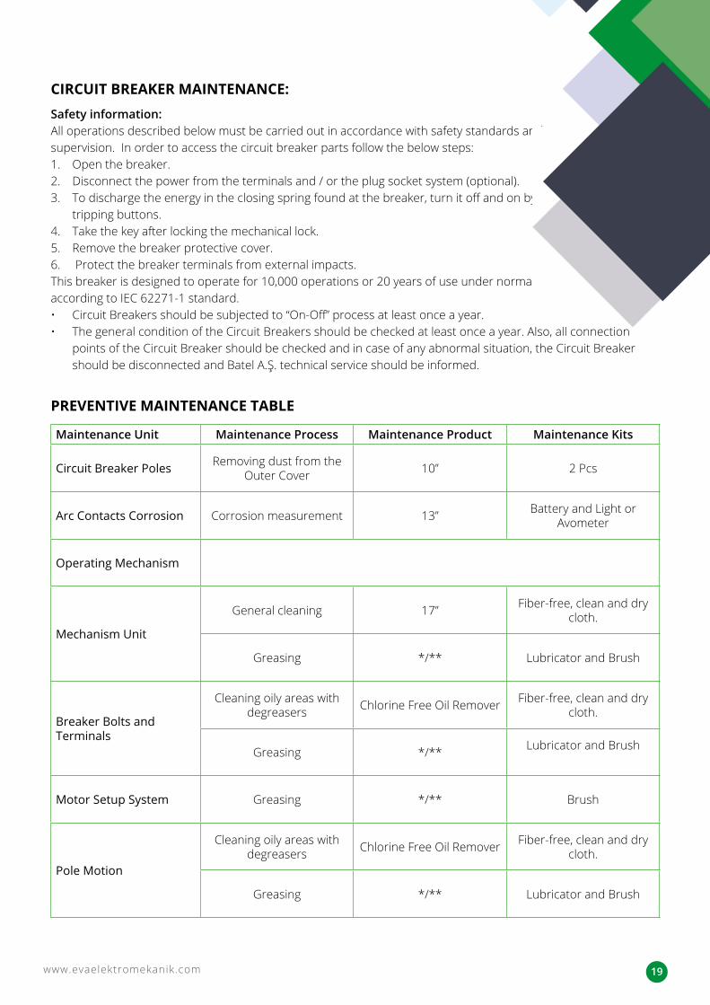
Maintenance Unit Maintenance Process Maintenance Product Maintenance Kits
Circuit Breaker Poles Removing dust from the Outer Cover 10’’ 2 Pcs
Arc Contacts Corrosion Corrosion measurement 13’’ Battery and Light or Avometer
Operating Mechanism
Mechanism Unit
General cleaning 17’’ Fiber-free, clean and dry cloth.
Greasing */** Lubricator and Brush
Breaker Bolts and Terminals
Cleaning oily areas with degreasers Chlorine Free Oil Remover Fiber-free, clean and dry
cloth.
Greasing */** Lubricator and Brush
Motor Setup System Greasing */** Brush
Pole Motion
Cleaning oily areas with degreasers Chlorine Free Oil Remover Fiber-free, clean and dry
cloth.
Greasing */** Lubricator and Brush
www.evaelektromekanik.com20
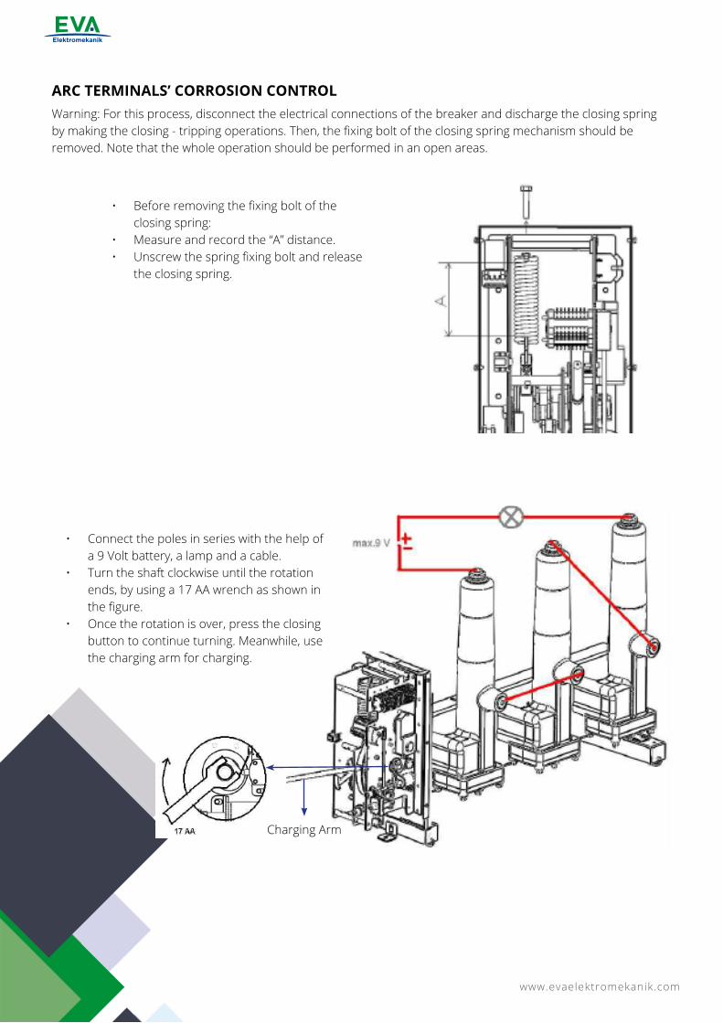
ARC TERMINALS’ CORROSION CONTROLWarning: For this process, disconnect the electrical connections of the breaker and discharge the closing spring by making the closing - tripping operations. Then, the fixing bolt of the closing spring mechanism should be removed. Note that the whole operation should be performed in an open areas.
• Before removing the fixing bolt of the closing spring:
• Measure and record the “A” distance.• Unscrew the spring fixing bolt and release
the closing spring.
Charging Arm
• Connect the poles in series with the help of a 9 Volt battery, a lamp and a cable.
• Turn the shaft clockwise until the rotation ends, by using a 17 AA wrench as shown in the figure.
• Once the rotation is over, press the closing button to continue turning. Meanwhile, use the charging arm for charging.
www.evaelektromekanik.com 21
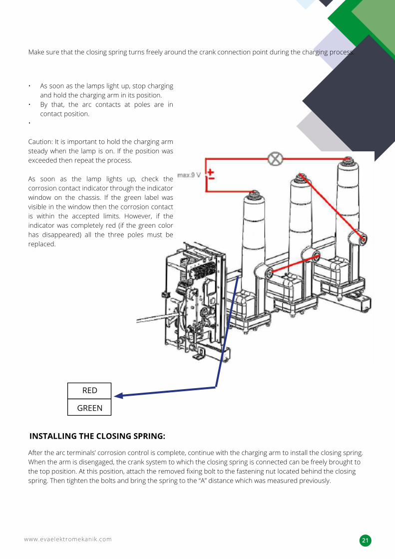
INSTALLING THE CLOSING SPRING:
Make sure that the closing spring turns freely around the crank connection point during the charging process.
After the arc terminals’ corrosion control is complete, continue with the charging arm to install the closing spring. When the arm is disengaged, the crank system to which the closing spring is connected can be freely brought to the top position. At this position, attach the removed fixing bolt to the fastening nut located behind the closing spring. Then tighten the bolts and bring the spring to the “A” distance which was measured previously.
RED
GREEN
• As soon as the lamps light up, stop charging and hold the charging arm in its position.
• By that, the arc contacts at poles are in contact position.
•
Caution: It is important to hold the charging arm steady when the lamp is on. If the position was exceeded then repeat the process.
As soon as the lamp lights up, check the corrosion contact indicator through the indicator window on the chassis. If the green label was visible in the window then the corrosion contact is within the accepted limits. However, if the indicator was completely red (if the green color has disappeared) all the three poles must be replaced.
www.evaelektromekanik.com22
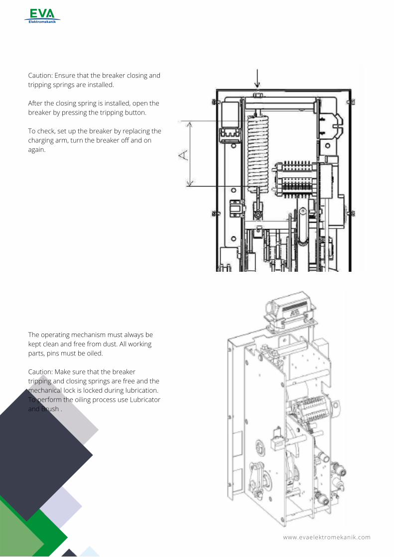
Caution: Ensure that the breaker closing and tripping springs are installed.
After the closing spring is installed, open the breaker by pressing the tripping button.
To check, set up the breaker by replacing the charging arm, turn the breaker off and on again.
The operating mechanism must always be kept clean and free from dust. All working parts, pins must be oiled.
Caution: Make sure that the breaker tripping and closing springs are free and the mechanical lock is locked during lubrication. To perform the oiling process use Lubricator and Brush .
www.evaelektromekanik.com 23
5.4- MV VOLTAGE TRANSFORMERS
5.5- MV CURRENT TRANSFORMERS
5.8 -RELAY AND METERING TOOLS
5.6 EARTHING DISCONNECTOR (EARTHING THE MV CABLE TERMINALS)
5.3 -MECHANISMS’ CONTROL
1. Open the cable connection compartment door of the cubicle.2. Check the conductor connections froming the main circuit to the MV Voltage Transformer and tighten the
loose bolts with 15-20Nm Torque if required.3. Ensure that the secondary connection terminals of the voltage transformers are not short-circuited.4. To determine that there are no cracks, fractures, carbonization marks or any defects on the voltage
transformer bushings’ body, wipe it with a dry cloth.5. Ensure that the MV fuses of the voltage transformer are in a good condition and are complete.
1. Open the cable connection compartment door of the cubicle.2. Check the conductor connections froming the main circuit to the MV Current Transformer and tighten the
loose bolts with 15-20Nm Torque if required.3. Ensure that the secondary connection terminals of the current transformers are not short-circuited.4. To determine that there are no cracks, fractures, carbonization marks or any defects on the current
transformer bushings’ body, wipe it with a dry cloth.
1. Check the connections of the relay and metering devices to the protection box and tighten the loose ones.2. Check if the relay and metering devices are operating properly.3. Check the conductors connection and tighten the loose ones.
1. Open the Cable Connection Compartment Door. If the door cannot be opened, check whether the cubicle’s earthing is performed or not, if not cubicle’s door can not be opened.
2. Check the conductor connections froming the main circuit to the Earthing Disconnector and tighten the loose bolts with 15-20Nm Torque if required.
3. To determine that there are no cracks, fractures, carbonization marks or any defects on the earthing disconnector bushings’ body, wipe it with a dry cloth.
1. Check the proper operating of the control mechanisms of all the used equipment and ensure that the indicators show the right positions.
2. M1 type mechanisms should be taken into general maintenance by the manufacturer after 2000 tripping and closing operations while the M2 type mechanisms should be taken after 10000 tripping and closing operations.
The Earthing Disconnector on the MV Cable terminals is accessed by opening the Cable Connection Door.
Circuit Breaker M1 (2000 Tripping/Closing), M2 (10.000 Tripping/Closing)
Load Break Switch M1 (2000 Tripping/Closing)
Disconnector M0
www.evaelektromekanik.com24
5.10-LV COMPARTMENT
5.11- MECHANICAL INTERLOCKING SYSTEM
5.12- AUXILIARY POWER SUPPLY
5.13 LIST OF TOOLS REQUIRED DURING MAINTENANCE AND INSTALLATION
1. Open the LV Compartment Cover and clean the inside area.2. Check if there is defective insulation in the control circuit and fix if it.3. Check the terminal connections and tighten the loose ones.
Check if the cubicals mechanical interlocking system is operating properly.
The manufacturer company guarantees the product against any material and operational defects for a period of 2 years within the conditions specified in the contract. In this 2-years period, if any malfunction is detected within the conditions specified in the contract, the manufacturer company may seek repair and / or replacement of the faulty products. Improper storage, use or repair of the equipment by the user other than the conditions specified in this user manual, constitutes a breach of the warranty and causes it to be null.
Check the auxiliary power supply (if any).
Tools Dimensions Quantity
Dirt Chemical Solution - -Clean Cloth - -Avometer - 1 PcMain Circuit Resistance Metering Tester - 1 PcOpen End Wrench 10’’, 13’’, 15’, 17’’, 19’’, 24’’ 2 PcSocket Wrench - 1 PcKısa Arakol - 1 PcSocket 10’’, 13’’, 15’, 17’’, 19’’, 24’’ 1 PcMachine Maintenance Oil - -Lubricator - -Brush - 1 PcChlorine Free Oil Remover - -Battery - -Light - -
• General maintenance to be made at least every two years. • It is recommended by our company for cubicals’s solid insulation materials used in VERY DIRTY
environments to be checked and cleaned once a year at latest.
FREQUENT MAINTENANCE
6 - GUARANTEE TERMS
5.9 -EARTHING CIRCUIT1. Check the continuity of the cubicles grounding circuit and tighten the loose bolts and nuts. Ensure that the
resistance between the grounding terminal and the metal body is 0.1 ohm at most.2. Check the cubicle ground terminals which are arranged side by side are properly and firmly connected to
each other and all the cubicles are connected to the main grounding system with a common grounding conductor.

www.evaelektromekanik.com 25
Switching The Future...
MET
AL
ENCL
OSE
D M
OD
ULA
R SW
ITCH
GEA
RS
(MM
MH
) USE
R G
UID
EEVA ELEKTROMEKANİK SAN. VE TİC. LTD. ŞTİ.
DAĞYAKA MAH. 2008. CAD. NO:5 KAHRAMANKAZAN, ANKARA, TÜRKİYE
Tel: +90 312 811 27 27 Fax: +90 312 811 27 28www.evaelektromekanik.com [email protected]