
Authors: Georgios Bakirtzis, Jason Phillips, Morgan Stuart ... · 3.3 Digital Camera — Canon T3...
20
VIRGINIA COMMONWEALTH UNIVERSITY DEPARTMENT OF ELECTRICAL AND COMPUTER ENGINEERING VCU AUTONOMOUS ROBOTICS GROUP Authors: Georgios Bakirtzis, Jason Phillips, Morgan Stuart Team: Georgios Bakirtzis, Joel Elmore, Morgan Stuart, Jason Phillips, Benjamin Young Advisor: Robert H. Klenke, Phd. Abstract The following paper details Virginia Commonwealth University UAV Group’s entry for the 2013 Student Unmanned Aerial Systems Competition (SUAS) competition. The autopilot components are designed primarily by graduate students in VCU’s UAV lab, while the aircraft payload is designed and built by undergraduates. The aircraft design combines knowledge from the nine years that VCU has been taking part in the SUAS competition and has been refined by the work of previous and current students. This report includes a system overview of the UAV and analyzes the necessary operational procedures that bound the flight of the aircraft.The aircraft consists of the VCU developed “NextGen” Flight Control System (FCS) and Ground Control Station (GCS) that autonomously guides the UAV through user designated waypoints and executes search patterns. In addition, the aircrafts payload combines still-image capture with location data in order to provide the ground station with geo-referenced images for computer-aided target recognition. Finally, additional failsafe mechanisms are in place in order to ensure safe and reliable operation of the vehicle.
Transcript of Authors: Georgios Bakirtzis, Jason Phillips, Morgan Stuart ... · 3.3 Digital Camera — Canon T3...
VIRGINIA COMMONWEALTH UNIVERSITY
DEPARTMENT OF ELECTRICAL AND COMPUTER ENGINEERING
VCU AUTONOMOUS ROBOTICS GROUP
Authors: Georgios Bakirtzis, Jason Phillips, Morgan StuartTeam: Georgios Bakirtzis, Joel Elmore, Morgan Stuart, Jason Phillips, Benjamin Young
Advisor: Robert H. Klenke, Phd.
Abstract
The following paper details Virginia Commonwealth University UAV Group’s entry forthe 2013 Student Unmanned Aerial Systems Competition (SUAS) competition. The autopilotcomponents are designed primarily by graduate students in VCU’s UAV lab, while the aircraftpayload is designed and built by undergraduates. The aircraft design combines knowledgefrom the nine years that VCU has been taking part in the SUAS competition and has beenrefined by the work of previous and current students. This report includes a system overviewof the UAV and analyzes the necessary operational procedures that bound the flight of theaircraft.The aircraft consists of the VCU developed “NextGen” Flight Control System (FCS)and Ground Control Station (GCS) that autonomously guides the UAV through user designatedwaypoints and executes search patterns. In addition, the aircrafts payload combines still-imagecapture with location data in order to provide the ground station with geo-referenced imagesfor computer-aided target recognition. Finally, additional failsafe mechanisms are in place inorder to ensure safe and reliable operation of the vehicle.
Table of Contents1 Introduction 4
1.1 Team . . . . . . . . . . . . . . . . . . . . . . . . . . . . . . . . . . . . . . . . . 41.2 Mission Requirements Analysis . . . . . . . . . . . . . . . . . . . . . . . . . . . 4
2 Design Analysis 52.1 Motivation . . . . . . . . . . . . . . . . . . . . . . . . . . . . . . . . . . . . . . . 52.2 Airframe . . . . . . . . . . . . . . . . . . . . . . . . . . . . . . . . . . . . . . . . 52.3 Flight Control System Overview . . . . . . . . . . . . . . . . . . . . . . . . . . . 72.4 Hardware . . . . . . . . . . . . . . . . . . . . . . . . . . . . . . . . . . . . . . . 72.5 Software . . . . . . . . . . . . . . . . . . . . . . . . . . . . . . . . . . . . . . . . 7
3 Payload 83.1 System Components . . . . . . . . . . . . . . . . . . . . . . . . . . . . . . . . . 83.2 Payload Component — BeagleBone . . . . . . . . . . . . . . . . . . . . . . . . . 93.3 Digital Camera — Canon T3 . . . . . . . . . . . . . . . . . . . . . . . . . . . . . 93.4 Operation . . . . . . . . . . . . . . . . . . . . . . . . . . . . . . . . . . . . . . . 9
4 Ground Control Station 104.1 Ground Control Station for the Flight Control System . . . . . . . . . . . . . . . . 11
4.1.1 Ground Control Station Control Client . . . . . . . . . . . . . . . . . . . . 114.1.2 Map Display . . . . . . . . . . . . . . . . . . . . . . . . . . . . . . . . . 114.1.3 Telemetry Panel . . . . . . . . . . . . . . . . . . . . . . . . . . . . . . . . 114.1.4 Telemetry Gauges . . . . . . . . . . . . . . . . . . . . . . . . . . . . . . 124.1.5 Parameter Control Forms . . . . . . . . . . . . . . . . . . . . . . . . . . . 12
4.2 Ground Control Station for the Payload System . . . . . . . . . . . . . . . . . . . 124.2.1 Image Collection . . . . . . . . . . . . . . . . . . . . . . . . . . . . . . . 124.2.2 Target Recognition . . . . . . . . . . . . . . . . . . . . . . . . . . . . . . 13
5 Safety Considerations and Approach 135.1 Nomenclature . . . . . . . . . . . . . . . . . . . . . . . . . . . . . . . . . . . . . 135.2 Radio Control (RC) Loss . . . . . . . . . . . . . . . . . . . . . . . . . . . . . . . 145.3 Ground Control Station (GCS) Communications Loss . . . . . . . . . . . . . . . . 145.4 Critical Battery Life . . . . . . . . . . . . . . . . . . . . . . . . . . . . . . . . . . 155.5 Further Analysis of Failure Modes . . . . . . . . . . . . . . . . . . . . . . . . . . 155.6 Minimizing Human Error . . . . . . . . . . . . . . . . . . . . . . . . . . . . . . . 15
6 Expectations and Results 166.1 Autonomy . . . . . . . . . . . . . . . . . . . . . . . . . . . . . . . . . . . . . . . 166.2 Imagery . . . . . . . . . . . . . . . . . . . . . . . . . . . . . . . . . . . . . . . . 166.3 Target Location . . . . . . . . . . . . . . . . . . . . . . . . . . . . . . . . . . . . 166.4 Mission Time . . . . . . . . . . . . . . . . . . . . . . . . . . . . . . . . . . . . . 176.5 Operation Availability . . . . . . . . . . . . . . . . . . . . . . . . . . . . . . . . . 176.6 In-flight re-tasking . . . . . . . . . . . . . . . . . . . . . . . . . . . . . . . . . . 17
VCU Autonomous Robotics Group Page 2
7 Conclusion 17
8 Acknowledgements 17
9 References 18
Appendices 19
A Checklists 19
VCU Autonomous Robotics Group Page 3
1 Introduction
1.1 Team
The Virginia Commonwealth Unmanned Autonomous Robotics Group is comprised of undergrad-uate students from the Electrical and Computer Engineering Department of the VCU School ofEngineering. The aircraft’s control systems are designed by the VCU UAV research lab and theaircraft’s payload systems are engineered by undergraduates at VCU. This will be the ninth yearthat VCU is taking part in the AUVSI competition.
1.2 Mission Requirements Analysis
The design of VCUs aircraft is the culmination of years of research and design, by both under-graduate and graduate students in order to build a system capable of competing in the StudentUnmanned Aerial Systems Competition (SUAS) competition. The SUAS exercise is intended tosimulate a military operation wherein the aircraft is dispatched to quickly gather intelligence aboutthe surrounding area. This dictates the operational boundaries of this exercise.
The competition rules outline the requirements as:
I Autonomy
II Imagery
III Target Location
IV Mission Time
V Operational Availability
VI In-flight re-tasking
Each category listed includes a minimum set of requirements defined as threshold of functionality.Additional requirements need to be satisfied in order to meet the full objectives of each category.For instance, the autonomy section specifies that the aircraft must be able to navigate through basicwaypoints and search a specific area. However, to fully complete the objective, the aircraft mustbe capable of autonomously performing all phases of the flight, including takeoff and landing. Theminimum threshold for imagery is to identify at least two target characteristics, but the completeobjective is to identify all five target characteristics. This prioritization structure is repeated for theother key performance parameters and will be described further in later sections.
The VCU Unmanned Aerial Vehicle team has strived to design and build an aircraft capable ofcompleting all threshold requirements while further pursuing each category’s full objective. Inorder to accomplish this, VCUs Unmanned Aerial System is designed to fly through designatedwaypoints while identifying targets on the ground. The aircraft is capable of relaying accurate andsufficient real-time data to the ground control operators for assessment and action. The payloadhas a field of view of 70 degrees while the cruise speed of the aircraft is typically 35 knots, or
VCU Autonomous Robotics Group Page 4
40 miles per hour. Given these parameters and the ideal situation, where the plane experiencesno deviation from the flight path and maintains a constant altitude of 714 feet, it is possible to flyover and take images of a 1 mile by 1 mile area in 7.92 minutes. This is 19.8% of the allowedmission window, leaving enough time to make another pass before landing while still processingdata. Extrapolating the above, it is also possible to gather data on a 2 mile by 2 mile area in 31.68minutes, which is 79.2% of the allowed mission window. The AUVSI operation does not takeplace in an area larger than 2 by 2 square miles, making the team confident that the system willbe able to perform the operation within the allowed time restraints. Fulfillment of the specificrequirements, and the systems that meet them, will be analyzed further in the Design Analysis,Payload, and Ground Control Station sections.
2 Design Analysis
2.1 Motivation
The airframe used for the system is a Radio Control (RC) model airframe, which was modified togive more payload capacity. The autopilot used for navigation was developed in-house by graduateresearchers at the VCU UAV lab. Unlike most commercial systems, VCUs autopilot is fully anddynamically tunable and was developed for flexibility. For similar reasons, the majority of theground station software was also developed in-house and it is coupled with the autopilot software.Further details are discussed below.
2.2 Airframe
Selection of the aircraft chassis was driven by the design goals of a low-cost, robust, stable, andcapable aircraft that could be easily repaired or replicated. Specific goals that influenced airframedesign include:
1. Twenty lbs. payload, not including fuel.
2. Payload bay with a minimum size of 9” wide by 10” tall by 12” long.
3. Endurance of 40 minutes, with adequate fuel and battery reserves.
4. Engine that is easy to start and capable of operating without failure for fifty or more flights.
5. Total airframe cost below $1000.
In addition, the aircraft needed to be easy to construct with materials readily available i.e., a COTSmodel aircraft.
Review of the available COTS model aircraft indicated that the possible candidates which satisfiedthese goals included the Rascal 100 from SIG Manufacturing Co., the Hobby Lobby 12’ Telemas-ter, and the Trainer 50 kit from Aircraft Modelers Research (AMR). Of the three, the AMR Trainer50 is the most robustly designed, as it can accommodate large gas engines of 50cc displacement.
VCU Autonomous Robotics Group Page 5
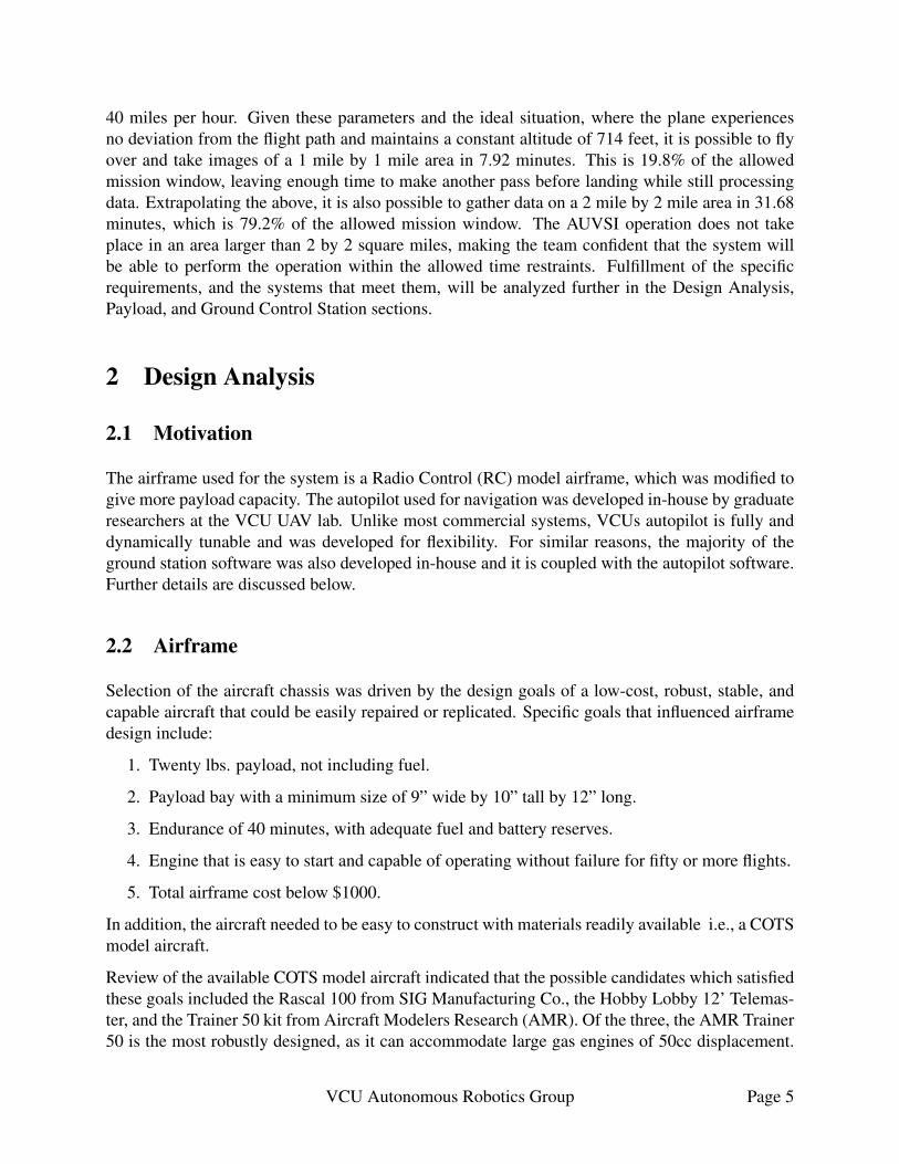
Figure 1: VCUs Autonomous Robotics Group aircraft.
Gas engine power offers the longest duration for the least amount of weight in fuel or batteriescarried. The AMR Trainer 50 kit, with engine, was the least expensive at $695 total, including the50cc gas engine.
The primary drawback of the Trainer 50 aircraft is its internal fuselage width, which is only 6” (acharacteristic that both the Telemaster and Rascal also share). However, the fact that the Trainer50 must be built from a kit, combined with its simple, sturdy construction using interlocking CADdesigned plywood parts, allowed the design to be easily modified for a 9” internal fuselage width.This was accomplished during building by designing and LASER cutting new fuselage formers ofthe required width. In addition, to increasing the width of the aircrafts fuselage, heavier duty land-ing gear, from AMR’s larger Payloadmaster 100 aircraft, were fitted to the Trainer 50 to provideadequate strength required by heavier payload weights.
As stated above, the Trainer 50 aircraft is powered by a 50cc gas engine made by DLE, Inc. Itturns a 22” wood propeller at approximately 6500 RPM, producing more than adequate thrust tolift a fully equipped aircraft with a full load of fuel and 20 lbs of payload weight. Endurance,with 80 oz. of fuel onboard is over 40 minutes. Normal aircraft control is provided by a COTSFutaba RC system operating on 2.4 GHz. The onboard RC receiver and servos are powered by adual-redundant battery system with a total capacity of 3.4 Ah, which is sufficient to operate theaircraft with a normal rate of control surface actuation for well over 3 hours. The aircraft also hassufficient battery capacity to operate the engine’s electronic ignition system for over 6 hours. Thepower system for the flight control system and payload is separate from the aircraft batteries, asdescribed in the following sections. Figure 1 displays the aircraft that VCU Autonomous RoboticsGroup will be competing with.
VCU Autonomous Robotics Group Page 6
2.3 Flight Control System Overview
The main design goals for the Flight Control System (FCS), were to have a system that performedwell, was reliable, flexible (i.e., modifiable by the end user), and easy to operate. These samedesign goals were what drove the first VCU UAV group to develop their own flight control systemfor the first competition and to continue to enhance and refine it since that time. The flight controlsystem used in this aircraft is the VCU-designed NextGen Flight Control System, the latest versionof the VCU FCS. This is an entirely custom, in-house design of an advanced dual-processor flightcontrol system, which was created as part of the ongoing research at VCUs UAV lab. NextGen wasdesigned to be as extensible as possible, to allow for advanced flight control algorithm research,thus it offers a far greater degree of flexibility and customization compared to commercially avail-able UAV autopilot systems. Extensive flight testing in a number of different aircrafts, includinghelicopters and commercial UAVs, have shown the NextGen FCS to be very capable, reliable, andeasy to use.
2.4 Hardware
NextGen uses a dual-processor system. One dedicated processor runs the flight control algorithms(the Flight Control Module, or FCM) and the other runs the sensor and communications interfaces(the Instrumentation Control Module, or ICM). This separation allows the flight control algorithmsto run unimpeded, without having to poll the sensor suite or communications channel. This leadsto a faster run rate for the FCS algorithms —200 Hz in the NextGen— as the FCS algorithm onlyneeds to check for new data from the sensor processor instead of actually processing it.
The ICM in NextGen handles all communication between the plane and the ground control station,as well as the interface to the onboard sensors. The ICM is designed for future expansion, and alsooffers a comprehensive sensor suite including static and dynamic barometric pressure, GPS, IMU,and battery voltage monitoring. It also interfaces directly with the 900 MHz MaxStream modemused for ground communication.
2.5 Software
The FCM in NextGen runs the flight control algorithms, which were developed in the VCU UAVlab. The FCM uses a Real-Time Operating System (RTOS), which in this case is a modifiedversion of Linux. The FCM software itself, as noted above, does not deal with sensors directly;rather, it communicates via a dedicated bus with the ICM. The FCS algorithms used are based onthe standard PID loop, and all of the PID parameters are fully tunable, in flight, from the groundcontrol station. This allows for the dynamic retuning of the aircrafts flight capability to compensatefor any changes in flight conditions.
The FCM software is designed to navigate using waypoint navigation. A waypoint is defined to bea position (latitude, longitude, and optionally altitude); a flightpath is an ordered list of waypointswhich dictate the path of the aircraft. The FCM software is capable of flying a pattern defined byup to 20 waypoints. The software also supports an additional loiter flight mode, where the aircraft
VCU Autonomous Robotics Group Page 7
will orbit a specified waypoint indefinitely; this is used, for example, in the RC or communicationsloss modes described in the safety section.
NextGen was developed by the VCU UAV lab primarily due to lack of customizable features ofcommercially available autopilots. Most commercial autopilots cost far more than NextGen andhave comparatively few features. NextGen features on-the-fly tunability of flight parameters duringa mission and offers far more flexibility in options offered to the user. One of the most critical partsof a mission is the ability to make in-mission choices and then implement the corresponding actioninto the UAV. With NextGen, we are able to change individual waypoints or even the entire flightpath if necessary, allowing for in-mission changes. More importantly, the PID controllers on theFCS can be tuned in-flight, which allows for on-the-fly adjustment of airframe flight performancewithout requiring the plane to land; this allows for a more stable and accurate flight even in theface of changing conditions.
3 Payload
The aircraft’s payload is the on-board system that facilitates the assembly of mission-critical dataand its transfer down to the ground station for analysis. The payload does not directly affect theaircrafts flight or maneuvering.
The following subsections describe the motivation behind each payload components’ selection andthe systems overall operation. Table 1 provides detailed information of the components used in thepayload system.
Table 1: Payload components list with specifications
Component Specifications
BeagleBone (BeagleBN) 720MHz AM3359 ARM Processor, 256MB DDR2,5V supplied, USB,I2C,UART,65 GPIO, 1.3W, 1.4 oz
Canon T3 12 MP CMOS Sensor, RAW/JPEG, 3:2 ratio in (4272 x 2848)(3088 x 2056) (2256 x 1504) (1920 x 480) (720 x 480)
Buffalo N450 Wireless 802.11 b/g/n system, 3 5dbi antenna array, 12V, 18W, 12 oz
Further detail for each component and how all work of them together will be given below.
3.1 System Components
The payload components on board the aircraft that are exclusive to image capture, telemetry cor-relation, and transmission, are the BeagleBone embedded computer, Canon EOS T3 camera, andthe Buffalo N450 wireless router. The integration of these components was designed and imple-mented to achieve reliable, high-quality ground reconnaissance for the mission. The partitioning
VCU Autonomous Robotics Group Page 8
of functionality into these separate components, described in following subsections, creates a moremodular system, allowing for manageable upgrades and replacements in the future.
3.2 Payload Component — BeagleBone
The BeagleBone is the foundation of the payload; it provides a point of access for the payload’sground systems, manages the camera and its images, and correlates GPS data with each image.The BeagleBone was chosen because it maintains low power consumption, averaging 1.3 watts,while still providing more than sufficient computational capacity. Its hardware support for standardwire protocols, such as SPI, I2C, and RS-232, further expands the BeagleBone’s potential. Finally,the BeagleBone is capable of supporting a full GNU/Linux operating system, allowing the team toleverage well-tested libraries and applications to deliver reliable services with ease.
3.3 Digital Camera — Canon T3
The team opted to move away from video imaging entirely, and instead based the system on theuse of still images. The Canon T3 delivers flexibility and important firmware support for its role asthe image capture device. The T3 can deliver variable resolutions of (4272 x 2848) (3088 x 2056)(2256 x 1504) (1920 x 480) and (720 x 480), along with fully adjustable shutter-speed, aperture,and ISO. Most importantly, however, the T3’s firmware supports remote control over a USB link.This allows a computer, in this case the BeagleBone, to initiate image capture and transmissionof the image to the attached computer. The gphoto2 command-line application is used to triggerthese actions on the T3 camera, via the BeagleBone, over a USB connection. This allows the rateof image capture to be controlled via relatively simple shell scripts.
3.4 Operation
In preparation for launch, the payload is powered and a (bash) script is executed onboard the Bea-gleBone that initiates periodic capturing of images, which are stored locally on the BeagleBone’smemory. Currently, the payload captures and stores images at the highest rate possible: one imageevery 1 to 2 seconds. The file names of the stored images represent the chronological order inwhich images are taken. Each image’s exif metadata is then populated with the GPS coordinatesof the plane’s location at the time of capture. This data is used in georeferencing target positions bythe ground station. These images are stored in the BeagleBone until the ground station initiates aremote transfer, downloading the images via the wireless link provided by the Buffalo router.
The store-and-forward mechanism described eliminates the potential for data loss due to link fail-ure, a problem that plagued the payload operation in previous years. Earlier methods of dataacquisition opted to send data from the capture device down to the ground immediately. If the datawas lost in the transmission, or if the wireless link was broken or otherwise flawed, the captureddata was lost and unrecoverable. In the new design, the images are stored on the BeagleBone until
VCU Autonomous Robotics Group Page 9
the ground station removes them, ensuring that data collected during a link failure is not lost anddata integrity is maintained.
This configuration also allows for remote access to the BeagleBone through ssh. This providessupport for the team to adjust the payload operation during flight if required. Manual configurationof the camera, control scripts, and wireless link are available during flight, allowing for immediatecustomization to adapt for unexpected scenarios.
4 Ground Control Station
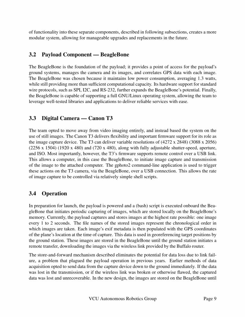
Figure 2: Ground Control Station’s Control Client.
The Ground Control Station is separated into two critical segments, which operate on differentsystems within the aircraft. One section is dedicated to the user end of the FCS, while the othersection interfaces with the payload. Both of these sub-stations can receive and transmit data to andfrom the aircraft in order to update the systems being used. Both partitions of the GCS will bedetailed below.
VCU Autonomous Robotics Group Page 10
4.1 Ground Control Station for the Flight Control System
The portion of the Ground Control Station (GCS) for NextGen is composed of two parts: the GCSServer and the FCS Control Station. The GCS Server communicates with the aircraft by way ofa serial MaxStream 900 MHz modem, and processes all packets received from the FCS. All validdata is stored internally and made available via a network socket to the FCS Control Station; thisallows, for example, the FCS Control Station to be run on a different computer than the GCSserver, if necessary.
The interface presented to the ground operator is shown below. This interface provides the operatorwith information on the operational status of the aircraft and FCS, as well as position and attitudeinformation. Using satellite imagery sourced from Google Maps, a birds-eye view of the currentarea of flight is shown; the ground operator can use this map to provide a desired flight path to theplane.
4.1.1 Ground Control Station Control Client
Figure 2 shows the GCS control client which consists of:
1. Map Display
2. Telemetry Panel
3. Telemetry Gauges
4. Parameter Adjustment Forms
These elements will be discussed further in the respective sections.
4.1.2 Map Display
The map display features a satellite image of the flight area overlaid with the vehicle’s currentposition, heading and flight path, the competition search areas, no fly zones, and identified targets.Flight control operators can add new waypoints and modify the flight path using a simple pointand click interface. Search areas and no fly zones can be modified in a similar manner. Whenentering waypoints, the interface will take no fly zones into account to prevent the operator fromplanning routes that would lead the vehicle out of the competition area. Waypoint changes willautomatically be uploaded to the aircraft and confirmed on the map display.
4.1.3 Telemetry Panel
The telemetry, which is not shown in Figure 2, displays various telemetry data. This data includes,the vehicle operation mode, which can be manual or autonomous; the altitude, above sea level andabove ground level is also shown; the latitudinal and longitudinal position of the aircraft, as wellas the orientation, pitch roll and yaw; the velocity info, in terms of airspeed, ground speed, and
VCU Autonomous Robotics Group Page 11
ground track; the battery levels and approximate flight time remaining; the status of the wirelesscommunications link as well as diagnostics information; and finally, the units of measure can betoggled between imperial, metric, or nautical, as needed.
4.1.4 Telemetry Gauges
Shown in Figure 2 are also telemetry data in the form of graphical instrument gauges for accessi-bility reasons. The gauge position, size, and units of measure can also be adjusted by the controloperators. As can be seen, the gauges available are altimeter, speedometer, compass, attitude. Thealtimeter displays both current altitude as well as target altitude. The speedometer displays air-speed and target airspeed. The compass displays the vehicle’s current heading and ground track.Finally, the attitude displays the vehicle’s current pitch and roll.
4.1.5 Parameter Control Forms
The control client also features collapsible parameter entry forms on the right hand size of thedisplay. This allows for quick access to flight parameters without cluttering the display area. PIDcontroller parameters and servo trim values can be adjusted as well.
4.2 Ground Control Station for the Payload System
The portion of the Ground Control Station (GCS) for the payload takes on many tasks. The corefunctionality of the ground payload system is the ability to download images from the aircraft andstore them safely. Those images are then accessible by other computers that can parse them forgeo-tags and location information, as well as target recognition and parameterization. This allowsfor a modular setup as computers can be added or removed based on the mission requirements.This modularization also allows new features to be implemented with less upheaval to adjacentsystems. For example, the host computer could pass all the images off to a computer dedicated toimage filtering and recognition, which will then make only the images that have targets in themavailable to the other computers. Alternatively, all the images could be stitched together and thenpassed on to other computers, which are dedicated to geo-referencing, filtering, and recognition.This arrangement allows for planned future growth. The sections below describe the current con-figuration.
4.2.1 Image Collection
In order to collect the images from the payload on the aircraft, a server in the ground stationrepeatedly checks to see if the UAV is in range and if there are any new photos available. Theserver uses netcat (nc) to check for connection and then rsync to move the files from the UAV tothe ground station for further processing. This server runs GNU/Linux, allowing for a great deal ofcontrol, customization, and general performance enhancements. The aforementioned functionality
VCU Autonomous Robotics Group Page 12
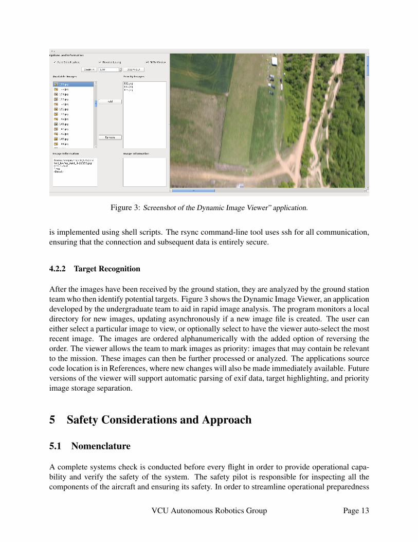
Figure 3: Screenshot of the Dynamic Image Viewer” application.
is implemented using shell scripts. The rsync command-line tool uses ssh for all communication,ensuring that the connection and subsequent data is entirely secure.
4.2.2 Target Recognition
After the images have been received by the ground station, they are analyzed by the ground stationteam who then identify potential targets. Figure 3 shows the Dynamic Image Viewer, an applicationdeveloped by the undergraduate team to aid in rapid image analysis. The program monitors a localdirectory for new images, updating asynchronously if a new image file is created. The user caneither select a particular image to view, or optionally select to have the viewer auto-select the mostrecent image. The images are ordered alphanumerically with the added option of reversing theorder. The viewer allows the team to mark images as priority: images that may contain be relevantto the mission. These images can then be further processed or analyzed. The applications sourcecode location is in References, where new changes will also be made immediately available. Futureversions of the viewer will support automatic parsing of exif data, target highlighting, and priorityimage storage separation.
5 Safety Considerations and Approach
5.1 Nomenclature
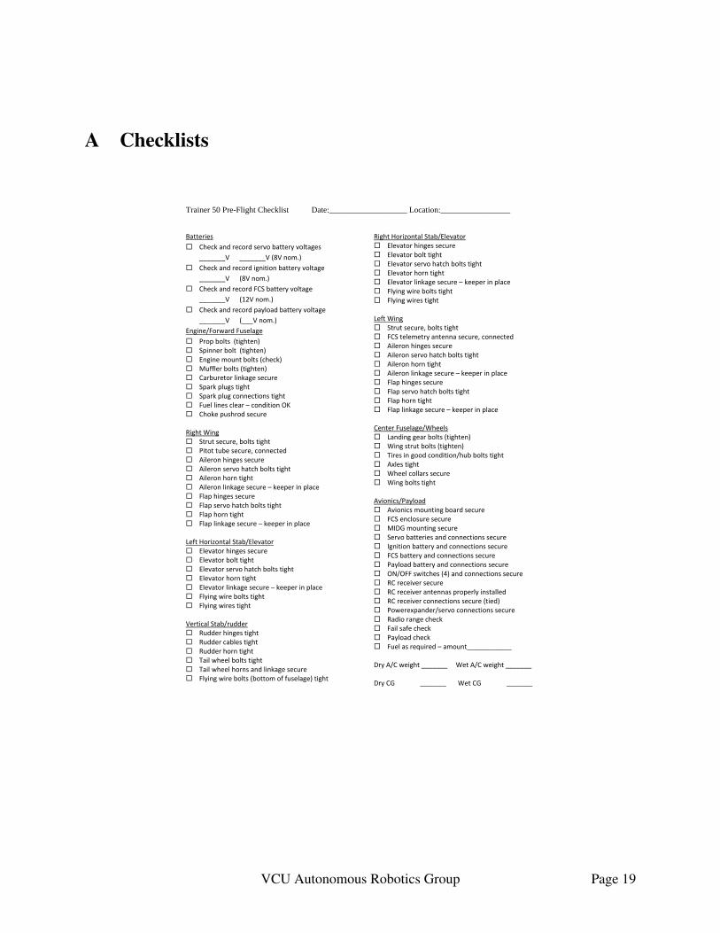
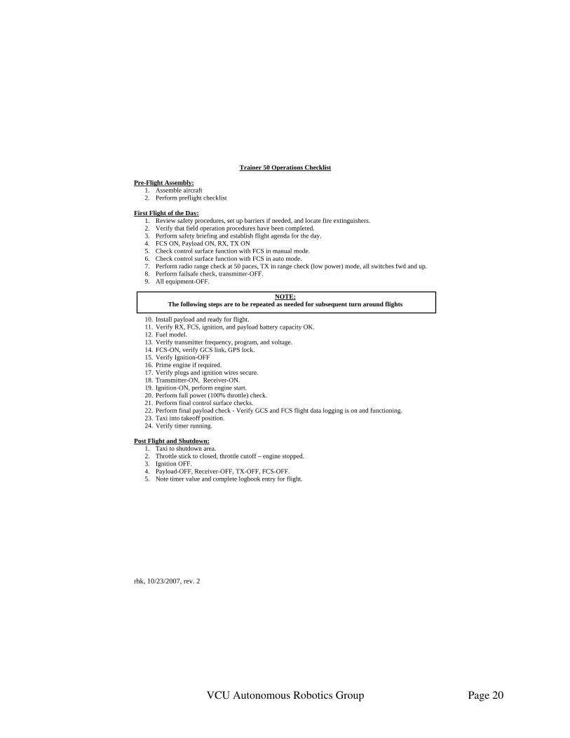
A complete systems check is conducted before every flight in order to provide operational capa-bility and verify the safety of the system. The safety pilot is responsible for inspecting all thecomponents of the aircraft and ensuring its safety. In order to streamline operational preparedness
VCU Autonomous Robotics Group Page 13
and to stress the importance of this step, the team has created two checklists. The first is for thepurpose of ensuring the correct and expected operation of the aircraft, while the second is for thepurpose of safety analysis. Both checklists are included in Appendix A.
The major aircraft inspections are:
1. Airframe structure.
2. Onboard electronics and wiring inspection.
3. Battery voltage check and recording.
4. RC functionality and range check.
5. FCS functionality check.
6. Payload functionality check
In-flight safety has also been considered and different flight modes have been created to provideessential safety features. For one, the plane is painted bright yellow in order for the crew to beable, to a reasonable extent, to locate it at any point in the sky. More importantly, the flight controlsystem incorporates additional flight modes that can be activated in the event of a system failure.These flight modes can either be activated by the safety pilot or the Flight Control Operator. Inaddition, if the aircraft is in auto pilot and the GCS or the RC radio signal is disrupted then it will“return home” and loiter at a rally point which is set automatically after successful takeoff. Thebehavior of the different failure modes is discussed below.
5.2 Radio Control (RC) Loss
In the event that the aircraft loses connection between the COTS RC transmitter and onboardreceiver, indicated by the throttle channel dropping to a lower predefined value, it will enter one oftwo failsafe modes depending on whether it is in autonomous or manual mode at the time of RClink loss. If it is in autonomous mode when the link is lost, then it will return to the rally point anddescend to four hundred feet altitude. If in manual mode when the link is lost, then it will proceedto do a low energy spiral to the ground with the throttle at idle.
5.3 Ground Control Station (GCS) Communications Loss
During normal autonomous operation, the Flight Control System (FCS) continuously sends “ping”packets to test the link to the Ground Control Station (GCS). If the FCS does not successfullysend and receive these “ping” packets to/from the GCS, it will enter a GCS Communications Lossmode. GCS Communications Loss mode is functionally identical to Radio Control (RC) loss modein that it will return to the rally point and descend to four hundred feet altitude.
VCU Autonomous Robotics Group Page 14
5.4 Critical Battery Life
It’s also of importance to ensure that the aircraft operates at optimal power levels. In order toensure that batteries are in condition to keep the aircraft safe, voltages are continuously monitoredby the Flight Control System (FCS) and directly transmitted to the Ground Control Station (GCS).Safe operating thresholds are calculated based upon the current aircraft distance from the rallypoint with an additional safety margin. If any battery voltage drops below this safety threshold,the Flight Control System (FCS) enters the “return home” mode and proceeds to return to the rallypoint.
5.5 Further Analysis of Failure Modes
Table 2 is a summary of possible failure modes and the corresponding responses of the team. It isan exhaustive list of the most pragmatic situations that might take place in a flight. These have allbeen tested multiple times by the team while flying and we are confident in our solutions.
Table 2: Failure Modes of the aircraft
Failure Response
Loss of RC Communication Ground Operators are notified.(Initial) FCS enters “return home” mode.
Loss of RC Communication(30 second mark)
Aircraft will execute flight terminationprocedure.
Loss of GCS Communication Ground Operators are notified.(30 second mark) FCS enters “return home” mode.
Loss of GPS Link RC Safety Pilot will take manual control.
FCS or Receiver batteries fall below criticallevels
Aircraft will execute flight terminationprocedure.
FCS battery dies RC Safety Pilot will take manual control.
5.6 Minimizing Human ErrorAlthough the safety of machine autonomy is critical for all operations, the importance of limitingthe team’s human error is still stressed. Furthermore, the autonomous systems themselves stillrequire human-assisted setup and monitoring. The team combats these potential failures withrepeated practice and development of the team’s flight execution. As the competition date drawsnear, the team places more focus on mimicking the competition restraints and committing eachmember of the team to a particular system, or duty, to focus on for the duration of the exercise. It isalso important to note that the checklists are primarily used in order to ensure that repeated flightsare possible with a minimum turnaround time by reducing the potential for human error as muchas possible.
VCU Autonomous Robotics Group Page 15
6 Expectations and ResultsThe VCU Autonomous Robotics Group has tested the aircraft continuously, in respect to bothground and in-flight procedures. Moreover, because of the nature of our system, the team hasmade numerous incremental changes that have been quality controlled over time to assure idealperformance. To that respect, the team has kept detailed logs of every flight, flight plan, and setup.The communications system setup has also been stress tested. Overall, the team believes that wehave a firm notion of how the system will perform, both in terms of drawbacks as well as theadvantages of our aircraft and flight procedures. Further detail will be given in the discussion ofeach element below.
Table 3: Functionality Assessment
Function Threshold Objective
Autonomy X XImagery X ?Target Location X XMission Time X XOperation Availability (A0) X XIn-flight re-tasking X X
6.1 AutonomyAutonomous takeoff and landing is currently being developed in the VCU UAV lab. However, it isnot yet “production-ready” for our team to use. Therefore, the aircraft is fully autonomous exceptfor manual takeoff and landing.
6.2 ImageryThe competition rules outline imagery based on how many characteristics the aircraft will be ableto identify. The imaging system has been implemented using a Digital Single Lens Reflex camera(DSLR). The DSLR provides more than sufficient image resolution to identify every characteristicof the targets. In addition, the image system uses a high-bandwidth Ethernet link to transmit theimages to the ground in near real-time. Thus, we are confident that we will receive high-resolutionimages of the target area on the ground for analysis during the competition flight. One potentialchallenge is that the current image system doesn’t have a gimbal implemented; the camera is on afixed position. This is overcome by ensuring that the aircraft can traverse the target area in such away as to bring it into the camera view field. Hence, the team is confident that we will be able toimage the targets adequately to achieve the threshold but, to reach the objective, we would have tobe directly above all of the targets.
6.3 Target LocationLocating targets is more straightforward; the exif data from the camera is going to be parsedby the Dynamic Image Viewer, which extracts and informs the team on the aircraft geo-locationduring the capture. This means that the system will be able to achieve the threshold requirement
VCU Autonomous Robotics Group Page 16
of 250 ft. However, through testing we are not confident that the precision will reach the objectiverequirement of 50 ft.
6.4 Mission TimeAs has been explained in Mission Requirements the team is confident that it can both achieve thethreshold and objective time constraints. The aircraft needs only 20% of the time to make a pass.However, depending on the situation it might need to do additional passes. Note that this is stillwithin time constraints for both the threshold and the objective for the mission window.
6.5 Operation AvailabilityExperience in the field indicates that we will not only be able to complete 50% of the missionwithin the original tasking window, we are confident that we will also achieve the objective ofcompleting the whole mission without any timeouts used.
6.6 In-flight re-taskingAs can be seen in Ground Control Station (GCS), and more specifically the Flight Control System(FCS) software, it is possible to add many waypoints as well as adjust the search area as necessary.The software has been used both with our aircraft and numerous other aircraft on a variety ofdifferent projects. At this point, the GCS/FCS has proven to be very stable.
7 ConclusionThe primary focus of our team has always been customizable autonomous systems that offer ex-ceptional operational flexibility. In that respect, the team believes it has achieved its goal. Ofcourse, using cutting edge research components can result in unexpected behavior. The team hasperformed troubleshooting and practice flights in order to be able to effectively identify and ad-dress a wide variety of unexpected behavior. In this manner, safety, stability, and reliability haven’tbeen downplayed in favor of flexibility in the implementation of the UAV.Virginia Commonwealth University School of Engineering has been participating in the AUVSIcompetition for nine years, motivating students to understand the design and implementation ofautonomous systems. The competition has been used as a means to this end, but also to enhancethe engineering skills of many undergraduate Electrical and Computer Engineering students. Thispaper has shown our approach to the complex systems engineering problem that has been offeredby this competition.
8 AcknowledgementsThe VCU SUAS 2013 competition team would like to thank the VCU School of Engineering andacknowledge the following individuals for their guidance and support throughout the developmentof this project. Each has selflessly contributed to making this project a possibility and as such
VCU Autonomous Robotics Group Page 17
we would like to extend our sincerest gratitude. Dr. Robert H. Klenke, Chair of the Electricaland Computer Engineering Department for being a steadfast mentor and for providing both labfacilities and financial support as well as being faculty advisor for the team. Graduate students atthe VCU UAV lab, Tim Bakker, Garrett Ward, and Joel Elmore for providing their expertise andfor always being readily available for help and support. Last but not least, we would like to thankour sponsors, Mark Sternheimer and the Virginia Aeronautical Historical Society, for making thisproject financially feasible.
9 ReferencesDeMott II, R. C. (2010). Development of a Flexible FPGA-Based Platform for Flight ControlSystem Research. M.Sc. Thesis. Virginia Commonwealth University: U.S.A.
Stuart, M. S. (2013). Dynamic Image Viewer [Computer Program]. Available athttps://github.com/Morgan243/Dynamic-Image-Viewer (Accessed 30 May 2013)
VCU Autonomous Robotics Group Page 18
A Checklists
Trainer 50 Pre-Flight Checklist Date:___________________ Location:_________________
Batteries
Check and record servo battery voltages
_______V _______V (8V nom.)
Check and record ignition battery voltage
_______V (8V nom.)
Check and record FCS battery voltage
_______V (12V nom.)
Check and record payload battery voltage
_______V (___V nom.)
Engine/Forward Fuselage
Prop bolts (tighten) Spinner bolt (tighten) Engine mount bolts (check) Muffler bolts (tighten) Carburetor linkage secure Spark plugs tight Spark plug connections tight Fuel lines clear – condition OK Choke pushrod secure Right Wing Strut secure, bolts tight Pitot tube secure, connected Aileron hinges secure Aileron servo hatch bolts tight Aileron horn tight Aileron linkage secure – keeper in place Flap hinges secure Flap servo hatch bolts tight Flap horn tight Flap linkage secure – keeper in place Left Horizontal Stab/Elevator Elevator hinges secure Elevator bolt tight Elevator servo hatch bolts tight Elevator horn tight Elevator linkage secure – keeper in place Flying wire bolts tight Flying wires tight Vertical Stab/rudder Rudder hinges tight Rudder cables tight Rudder horn tight Tail wheel bolts tight Tail wheel horns and linkage secure Flying wire bolts (bottom of fuselage) tight
Right Horizontal Stab/Elevator Elevator hinges secure Elevator bolt tight Elevator servo hatch bolts tight Elevator horn tight Elevator linkage secure – keeper in place Flying wire bolts tight Flying wires tight Left Wing Strut secure, bolts tight FCS telemetry antenna secure, connected Aileron hinges secure Aileron servo hatch bolts tight Aileron horn tight Aileron linkage secure – keeper in place Flap hinges secure Flap servo hatch bolts tight Flap horn tight Flap linkage secure – keeper in place Center Fuselage/Wheels Landing gear bolts (tighten) Wing strut bolts (tighten) Tires in good condition/hub bolts tight Axles tight Wheel collars secure Wing bolts tight Avionics/Payload Avionics mounting board secure FCS enclosure secure MIDG mounting secure Servo batteries and connections secure Ignition battery and connections secure FCS battery and connections secure Payload battery and connections secure ON/OFF switches (4) and connections secure RC receiver secure RC receiver antennas properly installed RC receiver connections secure (tied) Powerexpander/servo connections secure Radio range check Fail safe check Payload check Fuel as required – amount____________ Dry A/C weight _______ Wet A/C weight _______ Dry CG _______ Wet CG _______
VCU Autonomous Robotics Group Page 19
rhk, 10/23/2007, rev. 2
Trainer 50 Operations Checklist Pre-Flight Assembly:
1. Assemble aircraft 2. Perform preflight checklist
First Flight of the Day:
1. Review safety procedures, set up barriers if needed, and locate fire extinguishers. 2. Verify that field operation procedures have been completed. 3. Perform safety briefing and establish flight agenda for the day. 4. FCS ON, Payload ON, RX, TX ON 5. Check control surface function with FCS in manual mode. 6. Check control surface function with FCS in auto mode. 7. Perform radio range check at 50 paces, TX in range check (low power) mode, all switches fwd and up. 8. Perform failsafe check, transmitter-OFF. 9. All equipment-OFF.
NOTE:
The following steps are to be repeated as needed for subsequent turn around flights
10. Install payload and ready for flight. 11. Verify RX, FCS, ignition, and payload battery capacity OK. 12. Fuel model. 13. Verify transmitter frequency, program, and voltage. 14. FCS-ON, verify GCS link, GPS lock. 15. Verify Ignition-OFF 16. Prime engine if required. 17. Verify plugs and ignition wires secure. 18. Transmitter-ON, Receiver-ON. 19. Ignition-ON, perform engine start. 20. Perform full power (100% throttle) check. 21. Perform final control surface checks. 22. Perform final payload check - Verify GCS and FCS flight data logging is on and functioning. 23. Taxi into takeoff position. 24. Verify timer running.
Post Flight and Shutdown:
1. Taxi to shutdown area. 2. Throttle stick to closed, throttle cutoff – engine stopped. 3. Ignition OFF. 4. Payload-OFF, Receiver-OFF, TX-OFF, FCS-OFF. 5. Note timer value and complete logbook entry for flight.
VCU Autonomous Robotics Group Page 20


