Authors:- - CRISP Geotechnical Finite Elemenat … ANALYSIS OF SOILS IN SIMPLE...~ Authors:-Budhu....
12
~ Authors:- Budhu. M. and Britto. A.M. NUMERICAL ANALYSIS OF SOILS IN SIMPLE SHEAR DEVICES publication: SOILS AND FOUNDATIONS VOL. 27, NO 2, pp. 31-41 Year of publication:- 1987 ~ REPRODUCED WITH KIND PERMISSION FROM: Japanese Society of Soil Mechanics Sugayama Building 4F Kanda Awaji-Cho 2-23 Chiyoda-Ku, Tokyo 101,Japan
Transcript of Authors:- - CRISP Geotechnical Finite Elemenat … ANALYSIS OF SOILS IN SIMPLE...~ Authors:-Budhu....

~ Authors:-
Budhu. M. and Britto. A.M.
NUMERICAL ANALYSIS OF SOILS IN SIMPLE SHEARDEVICES
publication:
SOILS AND FOUNDATIONSVOL. 27, NO 2, pp. 31-41
Year of publication:-
1987
~
REPRODUCED WITH KIND PERMISSION FROM:Japanese Society of Soil Mechanics
Sugayama Building 4FKanda Awaji-Cho 2-23
Chiyoda-Ku, Tokyo 101, Japan

NUMERICAL ANALYSIS OF SOILS IN SIMPLE SHEARDEVICES
MUNIRAM BUDHU* and ARUL BRITTO**
ABSTRACTThe results of finite element analyses of soils in simple shear devices, assuming that
these soils can be modelled either as an elastic or an elastoplastic material, are presented.The results indicate that an elastic analysis produces larger levels of stress concentrationsthan an analysis using the modified Cam-clay model. The predicted stress-strain behaviorof a very loose sand and spes white kaolin using the modified Cam-clay model agrees verywell with simple shear test results deduced from measurements made at the sample coreof the top boundary of the samples for constant load tests. A satisfactory match ofexperimental and modified Cam-clay stress-strain results was not obtained for the constantheight test. The simple shear devices (Norwegian Geotechnical Institute and Cambridgetypes) can be expected to give good quality results for monotonic loading from carefullyprepared samples if measurements of stress and pore water pressures are made at thesample core on either the top or bottom or both horizontal boundaries of the sample.
Key words: clay, deformation, direct shear test, sand, stress distribution, stress-straincurve, (non-uniformiti~s) (IGC : D 6)
INTRODUCTIONLaboratory apparatus which can impose a
state of plane strain and allow the rotationof the principal axes of stress are desirable
,since this condition appears to simulate thestress state to which soils are subjected inmany practical situations. For example,soils adjacent to a friction pile or beneaththe fdundation of an offshore platform can be:expec~ed to deform in a manner similar to;simpl~ shear strain. Simple shear strain is
a form of plane strain in which an initiallycuboidal element is transformed into a paral-lelepiped without change in volume as shownin Fig. 1. For a uniform stress state to occurunder simple shear strain, equilibrium de-mands that complementary shear stresses bedeveloped on the vertical sides of the elementnormal to the plane of deformation.
Two apparatus with different purposes havebeen developed to supposedly impose simpleshear strain to soil samples. One, originallyproposed by Roscoe (1953) for research and
* Assistant Professor, Dept. of Civil Engineering, State University of New York at Buffalo,
Buffalo, NY 14260, USA.** Senior Research Associate, University of Cambridge, Cambridge, UK, formerly Visiting Assistant
Professor, SUNY AB, NY 14260, USA.Manuscript was received for review on May 27, 1986.Written discussions on this paper should be submitted before January I, 1988, to the Japanese Societyof Soil Mechanics and Foundation Engineering, Sugayama Bldg. 4 F, Kanda Awaji-cho 2-23,Chiyoda-ku, Tokyo 101, Japan. Upon request the closing date may be extended one month.

BUDHU AND BRITTO32
<-
y /[ ,,1-- 100y / I -1.
// I tyx" Ir--: /I 0',(£,'0)I
Fig. 1. Simple shear strain
continuously upgraded at Cambridge Univer-sity, tests a cuboidal sample (100 mm x 100mm x 20 mm high) between rigid boundaries(Fig. 2). Simple shear strain is appliedthrough two hinged end flaps which rotatewhen the bottom boundary of the deviceis horizontally displaced. The inner wallsof these end flaps are smooth so that signifi-cant shear stresses cannot be generated there.The other, originally proposed by Kjellman(1951) and modified by Bjerrum and Landva(1966) at the Norwegian Geotechnical Insti-tute (NGI) for practical use, tests a cylindri-cal sample (80 mm diameter x 20 mm high)laterally confined by a wire reinforced mem-brane between rigid top and bottom platens(Fi,l{.3). Simple shear strain is presumed
to be imposed by displacing the top boundary.Neither of these apparatus allows the devel-
opment of complementary shear stresses onthe vertical sides normal to the plane ofdeformation. As a result, the shear andnormal stresses must be non-uniformlydistributed to satisfy equilibrium (Wood,Drescher and Budhu, 1979; Budhu, 1984;Airey, Budhu and Wood, 1985).
In order to evaluate the practical effectsand actual distribution of normal and shearstresses, studies have proceeded along four ~different directions -analytical/ numerical(Roscoe, 1953; Duncan and Dunlop, 1969; ,
Lucks et al., 1972; Prevost and Hoeg, 1976;Hara and Kyota, 1977; Shen et al., 1978) ;experimental (Cole, 1967; Stroud, 1971;Budhu, 1979; Airey, 1984); comparisons ofsimple shear test results with results fromeither the triaxial or hollow cylinder appara-tus or both (Saada et al., 1983) ; and discus-sion (Vucetic and Lacasse, 1982).
In the analytical/numerical studies, elasticmaterial behavior was assumed and it wasshown that for the Cambridge simple shearapparatus (SSA) at least the middle one-third of the sample and for the NGI SSA,seventy percent of the sample could be ex-pected to deform uniformly. Detailed ex-perimental work in these devices is tediousand require sophisticated instrumentation andas such cannnot be conducted on a routinebasis. However, such tests in sands byStroud (1971) and Budhu (1979, 1984)did showthat the middle one-third of the samples I'"""
in monotonic tests deform uniformly in thesedevices but that non-uniformities predomi-nant at the ends spread rapidly during cyclicloading. Airey (1984), using a modified ver-sion of a specially instrumented NGI typedevice originally developed for sand byBudhu (1979), showed that the normalstresses are much more uniform for claysthan for sands.
Comparisons of simple shear test resultswith results from other devices-the triaxialand hollow cylinder apparatus-show that thesimple shear devices produce lower soilstrengths and stiffnesses and as a result sim-

33SIMPLE SHEAR TEST
pie shear devices have been dismissed (Saadaand Townsend, 1981). There is no obviousreason why simple shear test results shouldagree with results from triaxial or otherdevices unless the stress paths followed areidentical and the stresses imposed producesimilar changes in soil fabric.
In comparing results from various testingdevices, it is necessary to select appropriatestress and strain parameters. In simple sheartests, the intermediate principal stress (q.)
~ is neither independent of nor is it equal toeither the major or minor principal stresses.Consequently, the effect of the intermediatestresses should not be ignored as a rule.
Recent tests on clays (Airey, 1984) inan elaborately instrumented NGI type simpleshear device show that as the plasticity ofthe material increases so does the uniformityof boundary stresses. It appears that elasticanalyses produce results which perhaps showup the non-uniformities in simple sheardevices too pessimistically. Of course, soilis neither isotropic nor elastic. It is the in-tention of this paper to examine the distribu-tion of stresses and the mechanical behaviorof a sand and a clay in the simple sheardevices assuming these soils behave aseither elastic or elastoplastic materials.
~IELD SURPACE-
P
ELASTOPLASTIC SOIL MODEL
The model used is the modified Cam-claymodel which has been shown to predict themechanical behavior of normally and lightlyoverconsolidated soils (overconsolidation ratioless than 2) reasonably well (see for example,Wrot~, 1977). The details of this modelhavelbeen elaborated on by others (for exam-ple, JRoscoe and Burland, 1968; Wroth andHoulsby, 1985) and need not be attemptedhere. Essentially, the model consists of anellipsoidal yield surface in p, q space (Fig.4(a)) where:
1 p
Fig. 4. Modified cam-clay yield surfaceand e-p relationship
au is Kronecker deltaUj! is the effective stress tensorSj! is the stress deviator
During loading the yield surface expandsand this expansion is linked to the isotropicnormal consolidation line (Fig. 4 (b)). Thesoil parameters required for this model are:
). -the slope of the consolidation linec -the slope of the swelling line~ or M-the effective angle of friction or
the frictional constant at failurein (q, p) space respectively
G or II-the shear modulus or Poi~son'sratio
eA -void ratio at unit effective meanstress on the critical state line.
For simple shear strain tests, a knowledgeof either the magnitude of the intermediateprincipal stress or its relationship to theother two principal stresses is needed to deter-mine M. Unfortunately, the intermedjateprincipal stresses in simple shear devices arenot routinely measured or cannot be mea-sured as is the case for the NGI SSA.
(1)
(2)
p=(1/3) b'jJUjJ
ld q=(3/2 SjJSjVI/2
P is the mean effective stress
Q is the deviatoric stress

34 BUDHU AND BRITTO
,~.
,r-t-.,11
L-I ..100 1M ""=,:"",:,,",~
Finite Element Mesh usedFig. 5 (8).
Drained tests in the Cambridge SSA con-ducted by Stroud (1971) and Budhu (1979)on 14/25 Leighton Buzzard (LB) sand (av-erage grain size 1 mm) showed that
u2=m(u.+ua) (3)\vhere m is a constant, u. and Ua are themajor and minor effective principal stresses.
For 14/25 Leighton Buzzard sand m=O.37(Stroud, 1971). The authors are not awareof any such measurements in clays. As-suming values of m=O.4 to 0.5, then forsimple shear conditions:
M~';3sin<f> (4)
where sin<f>=(~ +ua)u, Ua fand the subscript f denotes failure.Numerical analyses were also conducted as-
suming that the test samples behave as iso-tropic elastic materials. In this case theelastic modulus (E) was calculated from the
expression:load.
(5
SIMPLE SHEAR TESTS
In conventional simple shear tests, thesoil sample is consolidated under K. conditionby applying a vertical stress and then sheardisplacements are subsequently imposed.Two types of tests are often carried out.One, called the constant load test, permitsthe passage of water from the sample throughporous stones placed on either the top orbottom boundaries or both, and the top bound-ary is allowed to move vertically to followthe compression or the dilation of the testspecimens. Constant load tests on sands aregenerally carried out on dry material. Theother, called the constant height test, issimilar to the constant load test but theheight between the top and bottom platensis kept constant. The reduction or increasein vertical stress required to maintain con-stant sample height is then related to thepore water pressures that might be developedin an undrained test under constant vertical
FINITE ELEMENT ANALYSIS
CRISP (Gunn and Britto, 1984) is a finiteelement program developed at CambridgeUniversity. The program allows predictionof plane strain, axisymmetry and three-di-mensional boundary value problems. Consti-tutive models included in the program arethe critical state models (Cam-clay, modifiedCam-clay) elastic and elastic perfectly plasticmodels. The modified Cam-clay and theelastic models are used in the present work.
A typical mesh used is shown in Fig. 5( a).The mesh includes the top and bottom metal-lic platens. These platens are assumed tobehave elastically. Each element is an eightnoded linear strain quadrilateral and the dis-placements are assumed to be quadratic func-tions of position coordinates. A 3 X 3 inte-gration scheme was employed.
The constant load test is simulated byfirstly consolidating the sample and thenprescribing horizontal displacements onl thetop platen with the bottom platen fixed.The top platen is permitted to move vertical-Iv. The vertical sides are assumed to be
SIMPLE SHEAR TEST 35
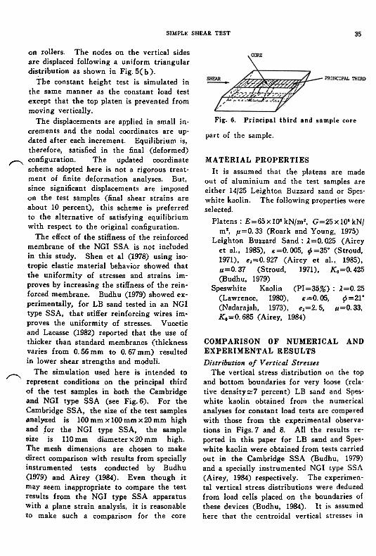
Fig. 6. Principal third and sample core
part of the sample.
on rollers. The nodes on the vertical sidesare displaced following a uniform triangulardistribution as shown in Fig. 5( b).
The constant height test is simulated inthe same manner as the constant load testexcept that the top platen is prevented frommoving vertically.
The displacements are applied in small in-crements and the nodal coordinates are up-dated after each increment. Equilibrium is,therefore, satisfied in the final (deformed)
(\ configuration. The updated coordinatescheme adopted here is not a rigorous treat-ment of finite deformation analyses. But,since significant displacements are imposedon the test samples (final shear strains areabout 10 percent), this scheme is preferredto the alternative of satisfying equilibriumwith respect to the original configuration.
The effect of the stiffness of the reinforcedmembrane of the NGI SSA is not includedin this study. Shen et al (1978) using iso-tropic elastic material behavior showed thatthe uniformity of stresses and strains im-proves by increasing the stiffness of the rein-forced membrane. Budhu (1979) showed ex-perimentally, for LB sand tested in an NGItype SSA, that stiffer reinforcing wires im-proves the uniformity of stresses. Vuceticand Lacasse (1982) reported that the use ofthicker than standard membranes (thicknessvaries from 0.56 mm to 0.67 mm) resultedin lower shear strengths and moduli.
~ The simulation used here is intended torepresent conditions on the principal thirdof the test samples in both the Cambridgeand NGI type SSA (see Fig. 6). For theCambridge SSA, the size of the test samplesanal~ed is 100 mm x 100 mm x 20 mm high~nd ,for the NGI type SSA, the samplesize is 110 mm diameter x 20 mm high.The mesh dimensions are chosen to makedirect comparison with results from speciallyinstrumented tests conducted by Budhu(1979) and Airey (1984). Even though itmay seem inappropriate to compare the testresults from the NGI type SSA apparatuswith a plane strain analysis. it is reasonableto make such a comparison for the core
MATERIAL PROPERTIESIt is assumed that the platens are made
out of aluminium and the test samples are
either 14/25 Leighton Buzzard sand or Spes-
~vhite kaolin. The following properties \vere
selected.
Platens: E=65x106kN/m2, G=25x106kN/
m2, p=0.33 (Roark and Young, 1975)
Leighton Buzzard Sand: ),=0.025 (Airey
et al., 1985), .:=0.005, t}=35. (Stroud,
1971), el=0.927 (Airey et al., 1985),
u=0.37 (Stroud, 1971), K. =0.425
(Budhu, 1979)
Speswhite Kaolin (PI=35%): ),=0.25
(Lawrence, 1980), .:=0.05, 9=21.
(Nadarajah, 1973), el=2.5, u=0.33,
K.=0.685 (Airey, 1984)
COMPARISON OF NUMERICAL ANDEXPERIMENTAL RESULTS
Distribution of Vertical StressesThe vertical stress distribution on the top
and bottom boundaries for very loose (rela-tive density:::7 percent) LB sand and Spes-white kaolin obtained from the numericalanalyses for constant load tests are comparedwith those from th~ experimental observa-tions in Figs.7 and 8. All the results re-ported in this paper for LB sand and Spes-white kaolin were obtained from tests carriedout in the Cambridge SSA (Budhu, 1979)and a specially instrumented NGI type SSA(Airey, 1984) respectively. The experimen-tal vertical stress distributions were deducedfrom load cells placed on the boundaries ofthese devices (Budhu, 1984). It is assumedhere that the centroidal vertical stresses in

BUDHU AND BRITTO36
'~~~=~I.", ""' .-" "','I , - -~- "' I
I ,';:.= =.-::--;- \ ~
\
\1
~".
~'.
(a) T. 0.6\ I T . 10\
Fig. 8. Vertical stress distribution onkaolin (constant load test)
are all normalized with respect to the ap-plied vertical stress (fa. By default all stressesare effective stresses. For LB sand the lattervalue is 100 kNfm2 and for kaolin it is 200
kNfm2.At low shear strain levels where elastic
behavior is expected to be predominant themodified Cam-clay and elastic analyses givesensibly the same results for LB sand (Fig.7( a ». However, there are significant dif-ferences between the numerical and experi-mental results at this strain level. The LBsand used in the experiments was in a veryloose state and during the consolidation phasevery small lateral movements of the hingedside walls of the Cambridge SSA was suffi-cient to cause a collapse of the loose sandstructure in the vicinity of these side walls.Thus, the differences between the numericaland experimental results may at least bepartially attributed to the non-uniformitiesinherited during the consolidation phase. Athigh strain levels (Figs. 7( b) and 8) wherenlastic behavior is nredominant. the elements
~ ~\\ ---(J a I \\s--=~-..,=:-:::::= - ~
0,.;...; '.'." . ..." ,. ..., ...~..:." c;'~ sand ;," ,".
, . ., . '.". ,
- ~
"~\\\-
- experiments- - modified cam clay il-- -- elastic
(b) Y-14"1.
Fig. 7. Vertical stress distribution onloose sand (constant load test)
the elements in the first and last rows CABand CD, 1 mm thick, Fig. 5) of the sampleobtained from the numerical analysis are ap-propriate for comparisons with the experi-mpnt..1 rp~111t~ Thp vprti"..l ~trp~~p~ (.roo)
37SIMPLE SHEAR TEST
~'y
(X1'E
/~~0.4~
- Experiments I Budhu, 1979)
. I I I I .!
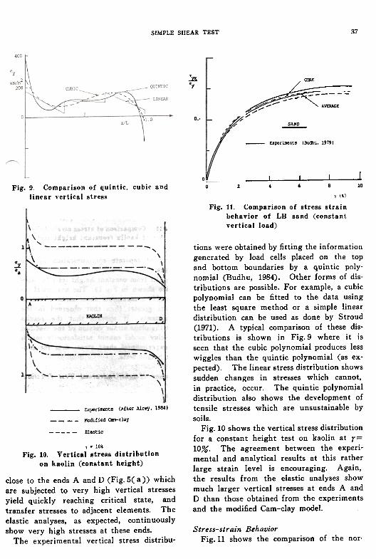
0 2 4 , 8 10Fig. 9. Comparison of quintic, cubic andlinear vertical stress y (\1
Fig. 11. Comparison of stress strainbehavior of LB sand (constantvertical load)
Experi~nt. (After Airey, 19841
- - - - Modified Ca!l'-clay
Elastic
tions were obtained by fitting the informationgenerated by load cells placed on the topand bottom boundaries by a quintic poly-nomial (Budhu, 1984). Other forms of dis-tributions are possible. For example, a cubicpolynomial can be fitted to the data usingthe least square method or a simple lineardistribution can be used as done by Stroud(1971). A typical comparison of these dis-tributions is shown in Fig.9 where it isseen that the cubic polynomial produces lesswiggles than the quintic polynomial (as ex-pected). The linear stress distribution showssudden changes in stresses which cannot,in practice, occur. The quintic polynomialdistribution also shows the development oftensile stresses which are unsustainable bysoils.
Fig. 10 shows the vertical stress distributionfor a constant height test on kaolin at r=10%. The agreement between the experi-mental and analytical results at this ratherlarge strain level is encouraging. Again,the results from the elastic analyses showmuch larger vertical stresses at ends A andD than those obtained from the experimentsand the modified Cam-clay model.
Stress-strain BehaviorFig. 11 shows the comparison of the nor.
y . 10\
Fig. 10. Vertical stress distributionon kaolin (constant height)
close to the ends A and D (Fig. 5( a)) whichare subjected to very high vertical stressesyield quickly reaching critical state, andtransfer stresses to adjacent elements. Theelastic analyses. as expected, continuouslyshow very high stresses at these ends.
The experimental vertical stress distribu-

38 BUDHU AND BRITTO
core
"xlkN/m2
40,P:5~§---
_average
./
y <\1
Fig. 13. Comparison of stress strain behav-ior of kaolin (constant height test)
subject of separate communication by theauthors.
Results from constant height tests for kao-lin are shown in Fig. 13. The numerical re-sults give a maximum shear stress about 40percent greater than that observed in theexperiments. It appears that the resultsfrom the plane strain version of the modifiedCam-clay model cannot satisfactorily matchthe experimental shear stress data for con-stant height tests.
malized shear stress ratio-shear strain re-sponse of LB sand if measurements \veremade at the sample core (Fig.6) and overthe top boundary for a constant load test.The latter measurements are those normallymade in routine tests. The experimentaland modified Cam-clay results show goodagreement. Both results show a differenceof shear stress ratio about 4 percent betweenthe sample core and the average on the top
boundary.A similar comparison for kaolin, except
now the shear stress on the horizontalboundary of the sample is reported (Airey,1984) rather than the normalized shear stressratio, is shown in Fig. 12. The numericalresults give no significant difference in shearstress between the sample core and the av-erage over the top boundary up to about 10percent shear strain whereas the experimen-:tal results show' a difference of about 16bercent. The numerical analysis did not ac-icount for slippage between the platens andsoils. Although techniques have been de-veloped to minimize slippage (Stroud, 1971;Budhu, 1984; Airey, 1984) some slippage atlarge strains could be expected during ex-periments using the simple shear devices.To account for slippage at platens-soil inter-face requires the use of slip elements inthe numerical analysis. . This would be the
Constant Height! Undrained Test Relation- r"shiP
Bjerrum and Landva (1966) proposed thatthe constant height test in the NGI deviceis similar to an undrained test and that thechanges in vertical stresses required to main-tain constant height are equivalent to thechanges in pore water pressures generatedin a constant load test if drainage of waterfrom the samples were prevented. There iscontroversy on this proposal. Saada et al.(1983) reported results from simple shear(NGI type device) and hollow cylinder testson Edgar Plastic Kaolin and Reid Bedfordsand which show that the changes in verticalstresses in constant height tests are not equiv-

39SIMPLE SHEAR TEST
1 mm layer at the sample core (Figs. 5( a)and.6). These results represent predictionsusing the modified Cam-clay model and theproperties of speswhite kaolin presentedearlier in this paper.
The changes in vertical stresses andchanges in pore water pressures in the twotypes of test show a maximum differenceof about 10 percent at a shear strain of 10percent. Of course, these predictions willvary depending on the choice of soil model.But, it is clear from Fig.14 that if thesample were to behave as a single element(as demonstrated for the sample core byanalysis and experiments) then one couldexpect (for all practical purposes) that thechanges in vertical stresses in a constantheight test would be directly related tothe changes in pore water pressures in a
constant load test conducted under undrainedconditions. However, good quality simpleshear tests in which the pore water pressuresand stresses are measured on the samplecore are required to further validate Bjerrumand Landva's suDDosition.
~
y 1\1
Fig. 14. Comparison of changes in verticalstresses with changes in pore water
pressures
CONCLUSION
It is indisputable that non-uniformities ofstress and strain develop in samples of soiltested in the two available simple shear ap-paratus. It is, however, not necessary todismiss these apparatus since meaningful re-sults, regardless of the plasticity of the soil,on the mechanical behavior of soils undermonotonic loading can be obtained by meas-uring the stresses and pore water pressureson the sample core.
It was shown in this paper that elasticanalyses tended to produce larger stress con-centrations at the ends of the sample inthe plane of shear deformation than analysesbased on the assumption that the behaviorof the soil specimens can be modelled bythe modified Cam-clay model. The experi-mental evidence suggests that the str~s-strain behavior of very loose 14/25 LeightonBuzzard sand and speswhite kaolin from con-stant load simple shear tests is satisfactorily
alent to the pore water pressures in constantload tests. They found that none of theirnormalization procedures was able to bringthe two results to equivalency. However,Vucetic and Lacasse (1984) presented resultsfrom anisotropically consolidated triaxial testson Drammen clay which are contrary to theresults reported by Saada et al. (1983).
Saada et al. (1983) were only able to meas-ure the average vertical stresses on presum-ably the top boundary of their samplesand it is not clear where pore water pres-sure measurements were made. There isno obvious reason to suppose that the triaxial
~ test results presented by Vucetic and Lacasse(1984) would be true for soils tested in thesimple shear devices. It seems intuitivelyplausible, however, that if a soil sample in~he simple shear devices were to deformps a si4gle element, then there should besome rflationship between the changes in'vertical stresses in a constant height test andthe changes in pore water pressure whichwould occur in a constant load test underundrained conditions.
Fig,14 shows the finite element resultsof the changes in vertical stresses dl1l1 andpore water pressures (du) from a constantheight test and a constant load test (un-drained conditions) respec,tively on the top

BUDHU AND BRITTO40
predicted by the modified Cam-clay modelThis is, however, not the case for constantheight tests. Even though the vertical effec-tive stress is reasonably well predicted bythe finite element program for kaolin, theshear stresses are overpredicted by about 50
percent.Experimental data from the sample core
of good quality tests are needed to validatethe supposition that the changes in verticalstresses in constant height tests are equiva-lent to the changes in pore water pressuresin constant load undrained tests in spite ofthe good agreement obtained from the nu-
merical analysis.
ACKNOWLEDGEMENTThe authors are grateful to Dr. D. M.
Wood and Dr. D. W. Airey for comments onthe draft version of this paper. Permissionto use the test results on NGI type SSAapparatus by Dr. D. W. Airey is appreciated.
REFERENCES1) Airey, D. (1984) : "Clays in circular simple
shear apparatus," Ph. D. Thesis, University ofCambridge, Cambridge, United Kingdom.
2) Airey, D., Budhu, M. and Wood, D. M. (1985):"Some aspects of the behaviour of soils insimple shear," Developments in Soil Mechanicsand Foundation Engineering-2, Editors, P. K.Banerjee and R. Butterfield, Elsevier AppliedScience Publishers, Ltd., London, pp.185-213.
3) Bjerrum, L. and Landva, A. (1966): "Direct sim-ple shear tests on a Norwegian quick clay,"Geotechnique, Vol. 16, No. I, pp.I-20. r
4) Budhu, M. (1979) : "Simple shear deformaticof sands," Ph. D. Thesis, University of Can'1-bridge, Cambridge, United Kingdom.
5) Budhu, M. (1984) : "Non-uniformities imposedby simple shear apparatus," Canadian Geotech-nical Journal, Vol. 21, No.2, pp.125-137.
6) Cole, E. R. L. (1967) : "The behaviour of soils inthe simple shear apparatus," Ph. D. Thesis,University of Cambridge, Cambridge, UnitedKingdom.
7) Duncan, J. M. and Dunlop, P. (1969) : "Behaviorof soils in simple shear tests," Proceedings 7 thInternational Conference on Soil Mechanicsand Foundation Engineering, 1, pp.l0l-l09.
8) Gunn, M. J. and Britto, A. M. (1984) : "CRISP-User's and programmer's guide," UniversityEngineering Department, Cambridge Univer-sity, Cambridge, U. K.
9) Hara, A. and Kyota, Y. (1977) : "Dynamic sheartests of soils for seismic analyses," Proceedingsof the 9 th ICSMFE, Tokyo, 2, pp.24-250.
10) Kjellman, W. (1951) : "Testing the shearstrength of clay in Sweden," Geotechnique,Vol. 2, No.3, pp.225-232. (
11) Lucks, A. S., Christian, J. T., Brandow, G. E. andHoeg, K. (1972) : "Stress conditions in NGI sim-ple shear test," Journal of the Soil Mechanicsand Foundations Division, ASCE, Vol. 98, SMI, pp.155-160.
12) Lawrence, D. (1980) : "Some properties as-sociated with kaolin soils," M. Phil. Thesis,Cambridge University, Cambridge, U. K.
13) Nadarajah, V. (1973) : "Stress strain propertiesof lightly over-consolidated clays," Ph. D.Thesis, University of Cambridge, Cambridge,U.K.
14) Prevost, J. H. and Hoeg, K. (1976) : "Reanalysisof simple shear soil testing," Canadian Geo-technical Journal, Vol. 13, No.4, pp.418-429.
15) Roark, R. J. and Young, W. C. (1975) : Formulas
NOTATION
p= mean effective normal stressq=deviatoric stressu=pore water pressureE=elastic moduluse.=void ratio at unit mean effective stress on
critical state lineG=shear modulusM=slope of critical state line
StJ=stress deviator tensor
r=engineering shear strain3tJ,",Kronecker delta
lC=slope of swelling lineJ.=slope of consolidation line.u=Poisson's ratio
qtJ=effective stress tensorql' q2' q,=effective major, intermediate and minor
principal stressesq.,=effective applied vertical stress
qz' qv' q,=effective normal stresses in x, y and z
dir~ctions r~spectively'rvz=shear stress
cf>=effective angle of internal friction~c,,=effective angle of internal friction at the
critical state'

SIMPLE SHEAR TEST 41
low stress levels in the simple shear appara-tus,' Ph. D. Thesis. University of Cambridge.Cambridge. United Kingdom.
22) Vucetic. M. and Lacasse. S. (1982) : 'Specimensize effect in simple shear test,' Journal ofthe Geotechnical Engineering Division. ASCE.Vol. 108. GT 12. pp.1567-1585.
23) Vucetic. M. and Lacasse. S. (1984) : Closure"Specimen size effect in simple shear test,'Journal of the Geotechnical engineering Divi-sion. ASCE. Vol. 110. No.3. pp.439-453.
24) Wood. D. M.. Drescher. A. and Budhu. M.(1979) : "On the determination of stress statein the simple shear apparatus,' GeotechnicalTesting Journal. GTJODJ. Vol. 2. No.4. pp.211-221.
25) Wroth. C. P. and Houlsby. G. (1985): "SoilMechanics-property characterization and analy-sis procedures,' Proceedings of the EleventhInternational Conference on Soil Mechanicsand Foundation Engineering. San Francisco.Vol. 1. pp.1-55.
26) Wroth. C. P. (1977) : "The predicted perform-ance of soft clay under a trial embankmentloading based on the Cam-clay model,' FiniteElements in Geomechanics. Editor. G. Gudehus.John Wiley and Sons Ltd., U. K.. pp.191-208.
for Stress and Strain, McGraw Hill.16) Roscoe, K. H. (1953) : "An apparatus for the ap-
plication of simple shear to soil samples," Pro-ceedings 3 rd International Conference on SoilMechanics and Foundation Engineering,
Zurich, Switzerland, I, pp.I86-191.17) Roscoe, K. H. and Burland, J. B. (1968) : "On
the generalized stress-strain behavior of 'wet'clay," in Engineering Plasticity 0. Heymanand F. A. Leckie, eds.), Cambridge UniversityPress, Cambridge, United Kingdom, pp.535-609.
18) Saada, A. S. and Townsend, F. C. (1981) : "State\ of the art: Laboratory strength testing of, soils," Laboratory Shear Strength of Soils,
American Society for Testing and Materials,STP 740, (Eds., R. N. Yong and F. C. Town-
send), pp.7-77.19) Saada, A. S., Fries, G. and Ker, C. C. (1983) :
"An evaluation of laboratory testing techniquesin soil mechanics," Soils and Foundations,Vol. 23, No.2, pp.98-112.
20) Shen, C. K., Sadigh, K. and Herrmann, L. R.(1978) : "An analysis of the NGI simple shearapparatus for cyclic soil testing," ASTM Dy-namic Geotechnical Testing, STP 654, pp.148-162.
21) Stroud, M. A. (1971) : "The behavior of sand at


![Engineering Fracture Mechanics · In fracture mechanics, some authors have applied the AE technique in order to identify the process zone [10] or to monitor the fracture parameters](https://static.fdocuments.us/doc/165x107/5e261ddfbfc1872d56106642/engineering-fracture-mechanics-in-fracture-mechanics-some-authors-have-applied.jpg)