AUTHORITY THIS PAGE IS UNCLASSIFIED · UNCLASSIFIED AD NUMBER AD396368 ... a Horizon Gyro Unit k. 3...
22
UNCLASSIFIED AD NUMBER AD396368 CLASSIFICATION CHANGES TO: unclassified FROM: restricted LIMITATION CHANGES TO: Approved for public release, distribution unlimited FROM: Distribution authorized to U.S. Gov't. agencies only; Foreign Government Information; 05 OCT 1965. Other requests shall be referred to British Embassy, 3100 Massachusetts Avenue, NW, Washington, DC 20008. AUTHORITY DSTL, AVIA 18/2114, 5 Dec 2008; DSTL, AVIA 18/2114, 5 Dec 2008 THIS PAGE IS UNCLASSIFIED
Transcript of AUTHORITY THIS PAGE IS UNCLASSIFIED · UNCLASSIFIED AD NUMBER AD396368 ... a Horizon Gyro Unit k. 3...

UNCLASSIFIED
AD NUMBERAD396368
CLASSIFICATION CHANGES
TO: unclassified
FROM: restricted
LIMITATION CHANGES
TO:Approved for public release, distributionunlimited
FROM:
Distribution authorized to U.S. Gov't.agencies only; Foreign GovernmentInformation; 05 OCT 1965. Other requestsshall be referred to British Embassy, 3100Massachusetts Avenue, NW, Washington, DC20008.
AUTHORITYDSTL, AVIA 18/2114, 5 Dec 2008; DSTL, AVIA18/2114, 5 Dec 2008
THIS PAGE IS UNCLASSIFIED

NOTICE: When goverment or other drawings, speci-fications or other data are used for any purposeother than in connection ith a definitely relatedgoverment procurement operation, the U. S.Government thereby incurs no responsibility. nor anyobligation whatsoevere and the fact that the Govern-ment my have foxmalated, furnished, or in any waysupplied the said drawings, specifications, or otherdata is not to be regarded by implication or other-vise as in any manner licensing the holder or anyother person or corporation, or conveying any rightsor permission to manufacture, use or sell anypatented invention that mey in any way be relatedthereto.
NOTICE:
THIS DOCUM4ENT~ COwNTNS INFORMATION
APFECTING THE NATIONAL EFNSE OF
THE UITED STATES WIT I THE MEAN-
ING OF THE ESPIONAGE LAWS, TITLE 18,
U.S.C., SECTIONS 793 and 794. TsE
TRANSKSSION OR THE REVELATION OF
ITS CONTENTS I Al MAMNR TO AN
UNAUTOR UPERSON IS PROINITE
BY LAW.
W&S. ONFIDENTIAL.MODIFIED HANLINGuAUTs
* ~~~GRADING Ai/ch/312Ny
MINISTRY OF AVIATION0
~ AEROPLANE AND ARMAMENTEXPERIMENTAL ESTABLISHMENT
BOSCOMEE DOWN
EVALUATION OF SPERRY GM7 COMPASS ISYST36 IN TIHE DIRECTIO.NAL
GYROSCOPE MODE.LJ
BY
SQNJ~. LDR. D.A. STONEROUSENAVIGATION MIAD RADIO DIVISION
BY T.{, ,:Q~A ' riOCIALusa-!Y T E IPHIhIT GO'/i.;. 1, 10 ANT
O'~C2- '.~':KI'T Ol. INAVY C-:!R WAYWCUj ll-S
2. Ti-1 II'1!FOR'IATIOfl SI IC.YD L_ -,,.. UARDCD UNDRIBRU .'S CZ:~ TO C!"L I .
2 D C FSECIJRiTY ';THAT I1A"',ED f'. :iA]ESTY'SGOVER,':H[E! IN T- UNITED t:N
I. " '~ 'ATT r":" ' ' A V: DOCUMENTSHo:U'! - rC C:: TULATr.) cI ,_ C:.''ERWMENT
.'2E VT! %VJT THE PRIOR PERMISSION OF THIMINISTRY OP AVIATION.4. TPF r,- ..... I,, ''ARNED THAT INFORMATIONCONTAINED IN THIS riOCUIIENT MAY BE SUBJECT TOPIVATELY -(5WNEr) RIGHTS.
MINISTRY OF AVIATION
IN D OOIW a lI MOMT I W NAf GOWUU4T AND 0 0 CAMMEION 6 CAMDO IM PftL=U ATTACffi TO Rf
ANY 09fliWGi OFE THRA MOUTI ACT. IU.I
adabi. ~~ b Ede ooo .0 todN a i.ms
isa Tes wIun w-dft psads ef iswos
"gU ICASTAIT, MINSTRY Of AVIATION, LONDON, W.Lm P= im = be ~su. sow pom wo be dhai m pus am ~ l&w
smw wi me a mbd *A.d am dstw" di w
U.S. CONFIDENTIAL-MO DIFIED HANDLIN~G AU-17~,, U.K. REsTRICTED/
"XOLUDED FROM AUTOMATIC REQRAOIK4QDOD DIR 5200.10 DOES NOT APPLY

wC.
Report No . o1SZ
,a04J3.,D E MI M M S IA I -5. M. SC5
RMOMsS DONN
by
Sqn. L D. I.. StonehouseNvation nd& Rao Dveo
L. *). Refs 1JVR 25/030ML04.0 H-'. Ref: L.3/568/osPeriod of Trials: Vrch 1965 - Pay 1965.
a Sperry G:"7 compass sy tom incorporates the CLII directional gyroscopeand is roll stabilised by an ternaZ horison reference. Trials of a GKi7
operated as an unslaved dirso onal gyroscope were conducted at Bosoobe Down.
The trials &owed that e long term heading stability of the sys& wasbetter than 0.3 hr., that e short term stability was better than 0. ., !
and that normal aircraft ouvres had little effect on the systoes
per ormance. They also rev led that certain precautions were necessary to
obtain optismi results fr the system.
DeTIS of the United St-to g . thifn the MOuIg of the
De Lav, itle 18, U. S. C., Section 7g5 and 794.-
its . or the "volat8 i s t5olt eb .i m
uin*P to em sthoraled eS 1pr±WA a.'
This Report is issued with the autority of )
Air Commodore,
Comandant, A. & A.1.1.
i Co. S. CO F IDE NTIA LM ODIFIED HANDLING AUTHOrVZED

- 2-
List of Contents
i. Introduction 3
2. Description of -Sperry G7 Compass System 3
3. Trials 1 ethod
4. Instrumentation and Installation 6
5. Trials Experience 6
6. Unserviosabilities . . 7
7. Results and nalysis 7
8. Conclusions . .13
9. ' eoommendations 13
Referenoes
List of Illustrations
Pi~ure
Latitude Controller Compensation I
Typical Taotical anoeuvre 2
/1. Introdction...

.U4J,-S. CONFIDENTIALI * ~nq4~iou, ODjFjED HANDLING AUTHORIZE
• s part of the Phase 3 modification of Shackleton aircraft the Gbhcopass was replaced by a dual Sperry GHi7 installation. Because these compassesinclude high precision directional gyroscopes, the possibility arose ofconducting operations with the -,ooos unsinved and operating in the dire-tional gyroscope (Ix.) mode. .n evaluation of the system'sa performance in theDG mode was authorised by i'av.l(b) (Headquarters letter 8/568/08 dated 23rd2, ebruary 1965 refers.) The aims of the trial were:-
(a) To determine the gyroscope's drift rate when operating in theDG; mode,
(b) to determine the accuracy of the gyroscope' s performance in turnsand manoeuvres, and
(o) to assess the performance of the gyroscope's bank out-out meohanism.
The ecquipment was installed in Comet 40 XS 235 in time for a first flighton 15th harch 1965. The early stages of the trial were carried out in conjuno-tion with other equipment trials, and it was not until 5th *ipril, 1965 that aflight was executed solely for the G117 trial. Seven sorties wore then necessar~yto complete tho data acquisition phase of the trial, with the final flighttaking place on Jth Eay, 1965. The equipment was removed from the aircraft on25t ray, 1965.
2. of ry€:7Cmassse opnns
The DG portion of the Sperry G '7 compass system consists of a CLIIdirectional gyroscope, a Horizon Gyro Unit k. 3 (H.G.U.), a compass master
*unit, a latitude controller, power supp.Ly units, amplifiers and synchrorepeaters.
The CLII is a reiongYroscope which is mounted in a roll ring with anominal roll freedom of 82 • The outer roll ring is stabilised in thisinstallation by an external horizon reference, the H.G.U. The inner ymbalis Iiaintained horizontal by a motor controlled by a liquid levelling switch.i4.rectlonal torcjue motors are incorporated on the Tro unit for the applicationof earth rate corrections. If the system is operated in the saved ( ; mode,the slaving signals are cut out by a\ micro-swith vihenever the bank angleexceeds 6 .
The H.G.U. is maintained vertical by a pair of liquid levellin switches,one fore and aft and the other ath~ertships. The fore and aft switch isslightly offset to compensate for pendlosity effect caused by the aircraft'8tendency to 'toe-in' during turns. In turns where the bank angle exceeds 10-the erection m:echarnism is disconnected and the H.G.U. is free runnin.
The compass master unit receives heading informat on from the CLII gyrro-scope by means of a synchro receiver equipped with a rotatable stator.flotation of th:;s starer is accomplished by means of a knob labelled O-X on thefacoe of the instrument. This allows the compass to be synobronised whenoperating in the slaved mode, or allows any desired headin," to be set whenoperating in the DG mode.
The latitude controller applies power to the eleotro-magnets of the torque' , motors in the CLII to counteract the apparent drift caused by earth rotation.~~The amount of precession is controlled bye poten ,.oaeter in the unit which is, oalibrated in degrees of latitude from 90 3 to 9 . Compensation is thus
•provided for drift rates varying bebvoen + 15o0 , /hour. ... lso inoorporated inthe latitude control~ler is a switching facility for selection of the magneti-
' 0cally slaved mode when this is included in the installation.
The CL11 gyr is maintained horisontal in the roll plane by signals~~derived from the H.G.U. These signals are obtained from a comparison of the~iL
output of the roll potentiometer incorporated in the HG.U. with that of a
i, second potentiometer geared to the roll ring of the CLII gyro. This signalSI.MODIID HANDLING AU'THORIZU "
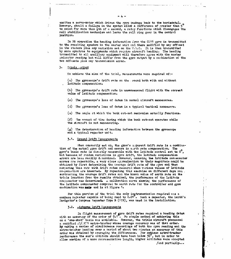
excites a servo-motor which drives the 'yro package back to the horisontal.Hoever, should a failure in the system-allow a difference of (reater than 5
to exist for more than ith of a second, a relay functions which disengages theroll stabilisation mechanism and locks the roll ring gear in the oentralposition.
In DG operation the heading information from the C11 gyro is transmittedto the receiving synchro in the master unit ana there modified by any off-setin the stators plus any variation set on the V.,S.C. It is then transmittedby more synchros to equipments which require aircraft heading. The headingtranswitted to all ancillary equipment will therefore agree with the master±ndLcator reading but will differ from the gyro output by a comibination of thetwo off-sets plus any transmission error.
3. rials ,,ethod
To achieve the aims of the trial, measurements were required of:-
(a) The gyroscope's drift rate on the round both with and withoutlatitude compensation.
(b) The gyroscope's drift rate in unmanoeuvred flight with the correctvalue of latitude compensation.
(c) The gyroscope's loss of datum in normal aircraft manoeuvres.
(d) The gyroscope's loss of datum in a typical tactical manoeuvre.
(e) The angle at whic h the bank cut-out mechanism actually functions.
(f) T.he amount of time during which the bank cut-out operates whilethe eircraft is not manoeuvring.
(g) The deterioration of heading information between the gyroscopeand a typical repeater unit.
3.1. Ground Drift 11easurements
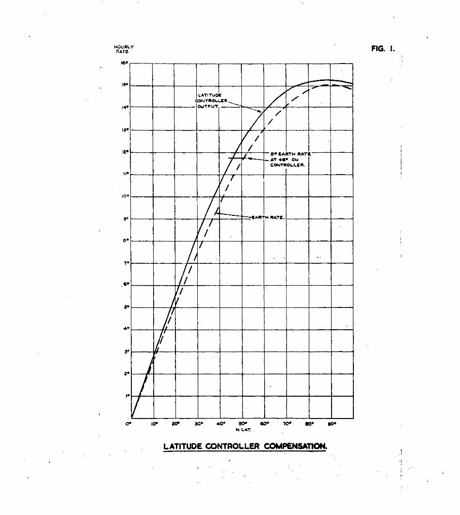
hen correctly set up, the gyro's nparent drift rate is a combina-tion of the actual gyro drift and errors in eo'.rth rate compensation. Thegyro's basic rate is directly measurable with the latitude control set to 0but because of random variations in gyro drift, the latitude compensationerrors are less readily &dtarmined. However, assuming the latitude com oensatorerrors are repeatable, a very close app:roximation to their magnitude could beobtained by first determining the average drift rate of the gyro and thencomparing this rato with drift rates measured when vwrious values of latitudeco:.enztion &re inserted. By repeating this exercise on different days andsubtracting the average drift rates and the known value of earth rate at thetria.ls location fro:i, the results obtained, the performance of the latitudecow ),nsater was determined. P. calibration curve showig; the performance ofthe latitude compensator compared to earth rate for the controller and gyrocouibination was made and is at Figure 1.
For this portion of the trial the only instrumentation required was acompass repeater capable of being read to 0.01 . Such a repeater, the Smith'sNavigator' s Compass Repeater Type B (3'CR), was used in the installation.
3.2. ,irborne Drift' easurements
In flight measurement of yo drift rates required a heading datumwith an acouracy of the order of 0.1". No simple method of achieving thison a 'one-shot' basis was available. However, the trials aircraft possesseda modified L /o,V TI astro-tracker whose average accuracy was of that order.By making a series of simultaneous recordings of both the gyro reading and theastro-trvcker heading over a period of about two minutes an accuracy of thisorder was obtained by averaging the differences. *,or optimum astro-trackerperformance the sun's altitude should have been below 30 , but in order toallow sorties of a more representative length, higher altitudes were accepted
/and partially...

-5-
and partially compensated for, by using more readings.
3.3. katntL :,o oXW hanoeuvres
;qeasuremants of the datum loss in manoeuvres were accomplished inthe same manner as for airborne drift measurements, but it was not possible toseparate, by direct measurement, datum losses occasioned by the manoeuvre fromthose occasioned by normal short term gyro drift between observations. Toprovide some meadure of licely error in turns approximotely 40 otservations(20 each port and starboard) of datum loss in 90", 180, and 360 turns weremade, and oomareod statistically with the likely value of short term gyro drift.In addition a limited numbes of measurements of datum loss were obtained afterturns of long duration (720 ) when the precession of the free-running H.G.U.would have allowed P. false vertical to be established.
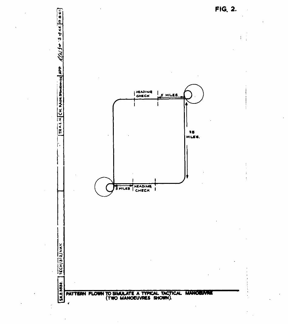
3.4. Zt,1MLosa in Taotioal Yianoeuvres
i.s a representation of the datum loss likely to be encountered on atypical tactical manoeuvre, measurements were made of the error occurrin% aftera fifteen minute manoeuvre (Figure 2). This manoeuvre oonsisted of a 90 turn,a straigh ax, d level run of approximately 25 miles, a 360 turn at rate oneand a 270 turn at rato two and finally a straight and level run of approximatelyfive miles. Because the trials aircraft operates at approximately twoe thespeed of the Shackleton, rate 8no turns were simulated by turns at 90 /min. andrate two turns by turns at 180 /Hin. in order to approximate the 'g' loadingoccasioned on the compass by the slower aircrf. .s a result the trialsaircraft was involved in turning for a longer period than would be the casewith the Shackloton and the loss of datum would be expected to be slightlygreater.
3.5. Bank Anile 1easurementis
To measure the angle of bank at which the bank out-out mechanismaotuawlly functioned, a simultaneous record of bank angle and the operation ofthe out-out switch was requiredi. This record was provided by instrumentingthe ll.G.U. potentiometer to give a single output of the entire range ofbmnkangle. This was obtained with only minimal effects on the potentiometervoltage, whereas the provision of -.n additional output to show the first 10°
to a higher order of precision degraded the roll stabilisation function, andwas therefore removed. The bank angle record, together with a record of theoperation of the bank cut-out micro-switch were presented side by side on aC.I.D. trce.
3.G. Bank Cut-out Time i.,easuremqnts
i- indication of the proportion of time during which the bank out-out switch was operatang during nominally straight and level flight was avail-able on the trace recordings described in para. 3.5-
3.7. Transmission Errors
To obtain a value for the heading transmission errors of the system,a simultaneous record of the gyro's heading and the heading oresented by atypical repeater was made. iny change in the difference between these readingswith heading was a measure of the transmission system errors. Because thegyro heading could not be determined to a greater accuracy than 0.1 withoutconsidereble alteration to the system, the gyro heading was recorded at thes me frequency as the astro-traoker data and at least 10 rMadings were averagedon every hoading to obtain a more accurate representation of transmissionerrors.
3-.U. Trials Plen
The complete trials plan, thus, consisted of four phases:-
(a) lpproximately 25 hours of ground running to calibrate thelatitude compensator and to determine the gyro's drift rate understatic conditions. /(b)..o

S-6-(b) Approximately 15 hours of straight and level flight todetermine the gyro's airborne drift rate.
(o) ipproximately 20 hours flying to determine the likely lossof heading datum in turns of various magnitudes, and
(d) .pproximately 10 hours flying to determine the likely lossof hepding datum in a typiol tactical manoeuvre.
4. Instrumentation and Installation
Because the regular aircraft auto-observer positions were not availableat the time of the trial, it was necessary to mount the entire GY7 installationon a palette fixed to the seat rails at the rear of the aircraft. Thispalette also contained facilities for two photographic auto-observers, one forthe N.C.R. and one for the CLII itself, and for the C.I.D. trace recorder. .ithree recording devices were connected with the aircraft's recording controlunit T7hich provided timing pulses synchronised with those of the astro-traokerand thus enabled simultaneous observations of true and gyro headings to be made.Because of the difficulties with the C.I.D. recorder described in para. 3.5-,this equi-:,i ont was unavailable until the last six flights, but, since theseflights were the only ones for hioh bank recordings wore particularly required,no significant loss of data resulted. The complete installation on the rearpalette thus consisted of:-
(a) i roll stabilised CLii gyro.
(b) AIl Horizon Gyro Unit Nk. 3.
(o) tA compass master indicator.
(d) N avigator's Compass Repeater, type B3.
(e) i latitude controller.
(f) it power supply unit.
(g) j servo-amplifier.
(h) Two camera auto-observers.
() .. C.I.D. trace recorder, and
(k) Switches and controls.
5. Trials Experienho
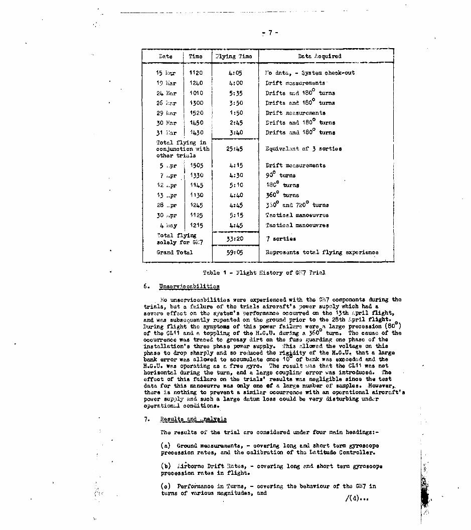
Ill the equipment except the C.I.D. recorder was installed in Comet 4CX3 235 on the 15th !laroh, 1965 and preliminary ground runs and airbornefunctional checks commenced immediately. Luring ground running the basicdrift rate of the gyro was established, and a calibration graph (Figure 1)prepared for the latitude controller. The aircraft was fully committed toother trials during the month of 1aroh, but advantage was taken of a number ofsorties flown for these trials to collect data on airborne drift rates. Aifterthe completion of the other trials, seven sorties totalling 33 hours 20 minuteswere reWuirod to complete the data acquisition phase of the GM7 trial. Thelast sortie was flown on 4th Nay, 1965, and after analysis of the data collectedon this fli ;ht had shown that no further sorties were required, the equipmentwas withdrawn from the aircraft on 25th Eay, 1965. Flight experience issumnarised in Table I.
/Table 1 ..
-7-
Date Time Mlying Time Data Acquired
15 I,1 r 1120 4:05 "e data, - System check-out
19 --iar 1240 4:00 Drift moasurements,
24 IIar 1010 5:35 Drifts mid 1800 turns
26 i":ar 1300 3:50 Drifts and 1800 turns
29 kL.ar 1520 1:50 Drift measurements
30 Mar 1450 2:45 Drifts and 1800 turns
31 iar 1430 3:40 Drifts and 1800 turns
Total flying inconjunction with 25:45 Equiv.lent of 3 sortiesother trials
5 -pr 1 1505 4:15 Drift measurements
7 ,..pr 1330 4:30 9d0 turns12 -pr 1145 5:10 1800 turns
13 ..pr 1130 4:40 3600 turns
28 -pr 1245 4:45 3 .0O and 720 turns
30 ..pr 1125 5:15 Tactical manoeuvres
4 Iay 1215 4:45 Tactical manoeuvres
total flyingsolely for GIL7 33:20 7 sorties
Grand Total 59:05 Represents total flying experience
Table I - Flight History of G-7 Trial
6. Unservicor-bilities
NIo unserviceabilities were experienced with the "P17 components during thetrials, but a failure of the trials aircraft's power supply which had asevwre effect on the system's performance occurred on the 13th pril flight,and was subsequently repeated on the ground prior to the 28th Ipril flight.During flight the symptoms of this power failure were a large precession (800)of the CLII and a toppling of the H.G.U. during a 360 turn. Tho cause of theoccurrence was traced to greasy dirt on the fuse guarding one phase of theinstallation's three phase power supply. This -21ced the voltage on thisphase to drop sharply and so reduced the rig~dity of the H.G.U. that a largebank error was allowed to accumulate once 10 of bank was e=oeded and theH.G.U. was operating as a free gyro. The result was that the CLII was nothorisontal during the turn, and a large coupling error was introduced. Theeffect of this failure on the trials' results was negligible since the testdata for this manoeuvre was anly one of a large number of samples. However,,there is nothing to prevent a similar occurrence with an operational aircraft'spower sup,)ly and such a large datum loss could be very disturbing undcroperation~l conditions.
7. ,lLeults -nakys3
The results ofZ the trial are considered under four main headings:-
(a) Ground measurmnents, - covering long and short term gyroscopeprecession rates, and the calibration of the Latitude Controller.
(b) Lirborne Drift Rates, - covering long and short term gyroscopeprecession rates in flight.
(o) Perfonanoo in Turns, - covering the behaviour of the GH7 inturns of various magnitudes, and /(d)...
', eel
(d.) :erf ormar.ce in manoeuvres, - covering the perfo. mance of thec-: :7 in a sinul ..te ac -! imnoeu-re.
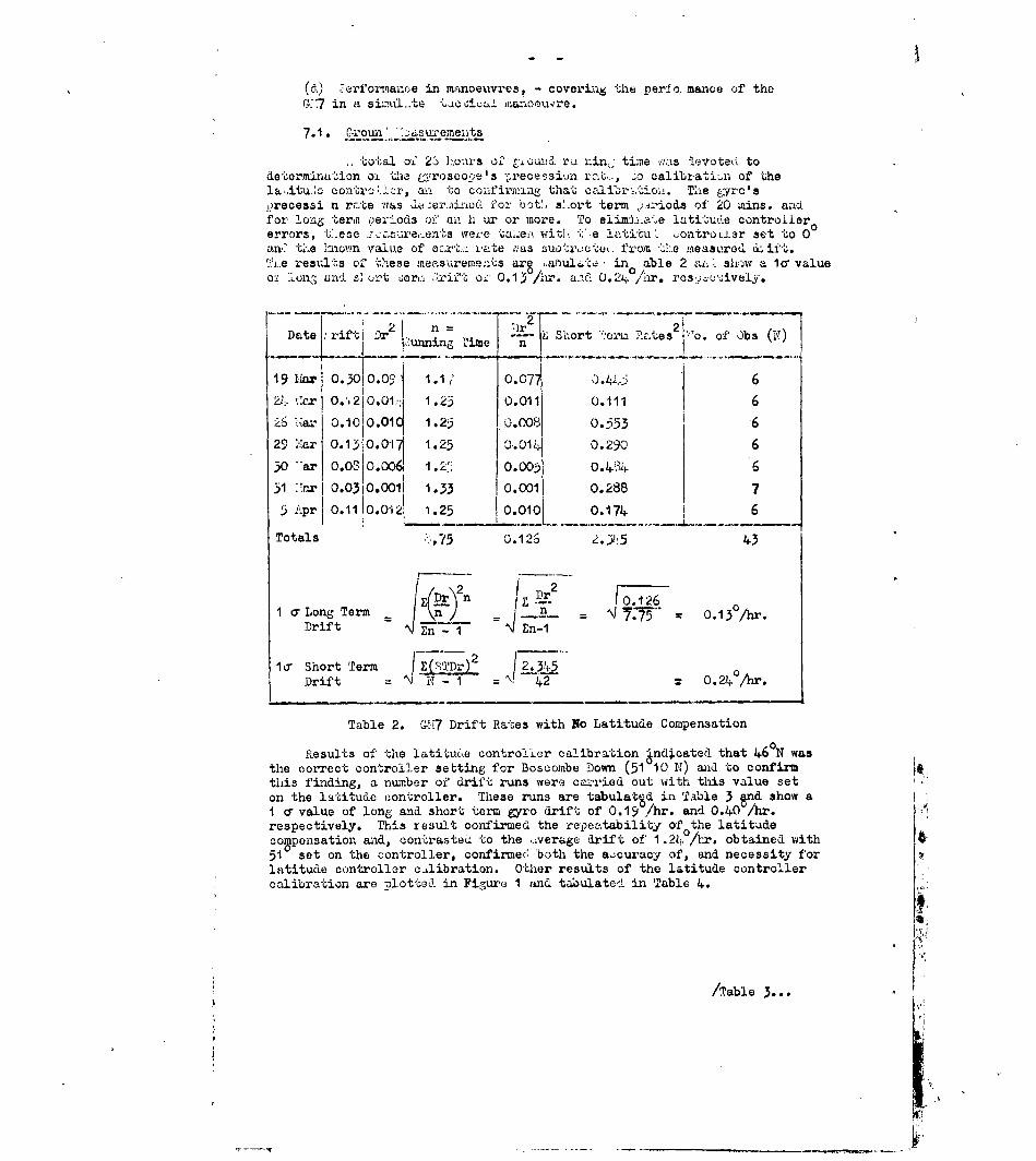
7.1. Qxrotun '.:2:Lz eme-n ts
tot.al ofI 2. ].ours o.' t.o-x(fI ra nin,; timne vI:s levoted. todetermination o' the yrosco.e.e's ";recessiun ra,.., zo calibration of thelaitu.e oontrc:.r, a-- to coinfirmngne that calibr-.tio±i. The gyro'sj.recessi n rc.te was "er.incd for botL, s'ort term .' -iods of 20 rains. anafor long terin per- ods of an h ur or more. To elimj.-."ae latitude contro.Liererrors, t.ese ... asare,:.en's weve ta:e.. e latitu' ontroi.j.ar set to 00an. t.e hnown value of ec.rt..:r ate ,as suo',.cte , fr.-om -l!:.e Lieasured d(ift.The results of these meaesuremests are .abulte in able 2 ain, shr'w a la valueo: -l and s] o-t uer, ;'.rif-t o-W 0.13°/r. a.1 0.24 /hr. rcs..,c',;iveIy.
Date .'.rif !" -' . . .n. : L Short ".,Ora RTotes 2 1 o. of ,)bs ()• | g unel n I o
19ar 0.3010.,;, 1.1 o.077 ) -, 6
22. c.r O..210.1:: 1.23 0.011 0.111 6
26 ,t.ar o.10 0.01 1.2: 0.008 0.553 6
29 1Li7ar 0. 13!0.O 0- 1.25 01.0114 0.290 630 "ar o.oS3o.0oo 1.2 0.005 0.4) 3 6
31 '.Tarl 0.0.'10.001 1 .33 0.001 0.288 75 Apr 0.1110.012i 1.25 0.010 0.174. 6
Totals 1,75 0.126 2.Y:5 43
Z iDr 2
n 0- - O 1 2 61 aLong Term 7 _ n 7--.75"n"2 0.13°Ar.
Drift n 1n-12SLa Short Term (Dr 2.345
Drift = K - - 0.24 /hr.
Table 2. G1,17 Drift Rates with No Latitude Compensation
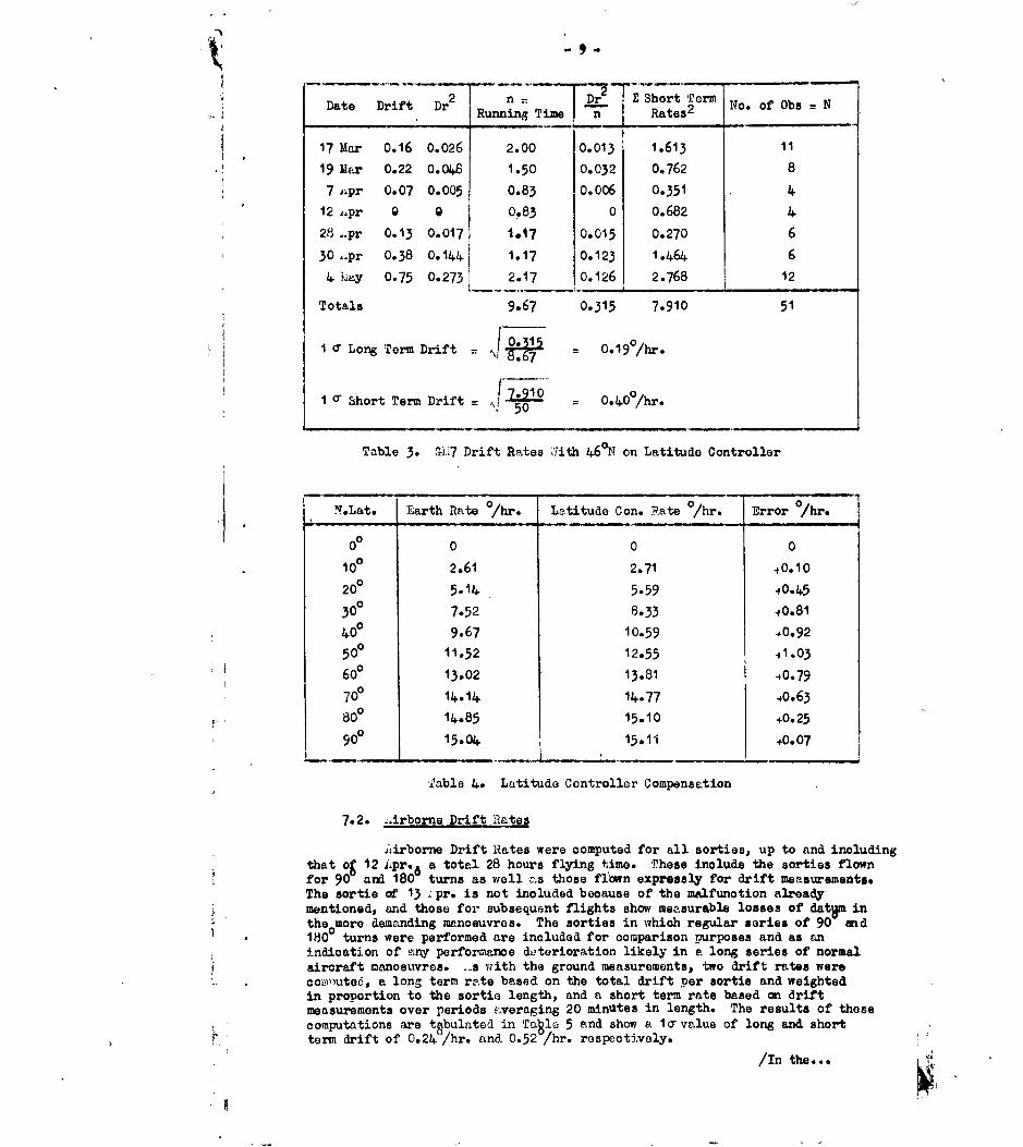
Results of the latitu6.e controlier calibration ind~cated that 46 N wasthe correct controller setting for Boscombe Down (51 10 N) and to confirmthis finding, a number of' drift runs were ca-ried out with this value seton the latitude controller. These runs are tabulatSd in Table 3 Snd show aI a value of lone and short term gyro drift of 0.19 A/hr. and 0.40 /hr. A
respectively. This result confirmed the repeatability of the latitude
compensation and, oontrasted to the ,.verage drift of 1 .24 0 /hr. obtained with51 set on the con-troller, confirmed, both the accuracy of, and necessity forlatitude controller c,,libration. Other results of the latitude controllercalibration are plotted in Figure 1 and tabulated in Table 4.
/Table
-'-
2 n Dr E ShortTormDate Drift Dr RunningTimelnj Rates 2 No. of Obs N
17 Mar 0.16 0.026 2.00 0.013 1.613 11
19 Mar 0.22 0.048 1.50 0.032 0.762 8
7 iipr 0.07 0.005 0.83 0.006 0.351 4
12 Lpr 9 0 0.83 0 0.682 4
28 -pr 0.13 0.017 1.17 0.015 0.270 6
30 ,Ipr 0.38 0.144 1.17 0.123 1.464 6
4 Lay 0.75 0.273 2.17 0.126 2.768 12
Totals 9.67 0.315 7.910 51
I a Long Term Drift = P 0.67
1 0 Short Term Drift .90
4500.0hr
Table 3. G:7 Drift Rates 'iith 460 N on Latitude Controller
X.Lat. Earth Rate /hr. Latitude Con. Rate °/hr. Error e/hr.
0 0 0 0
100 2.61 2.71 40.10
20 0 514.59 045
300 7.52 8.33 +0.81
40° 9.67 10.59 40.92
50 11.52 12.55 1.03
600 13.02 13.81 40.79
70° 14.14 14.77 40.63
800 14.85 15.10 +0.25
90 15.04 15.11 +0.07
Table 4. Latitude Controller Compensation
7.2. -irborne Drift Rlates
ALirborne Drift Rates were computed for all sorties, up to and including
that og 12 Lpr.6 a total 28 hours flying time. These include the sorties flownfor 90 and 180 turns as well zs those flown expressly for drift measurements.The sortie of 13 ;pr. is not included because of the malfunction alreadymentioned, and those for subsequent flights show measurable losses of datuM intheomore demanding manoeuvres. The sorties in which regular series of 90 and180 turns were performed are included for comparison purposes and as anindication of E ny performance deterioration likely in a long series of normalaircraft manoeuvres. ...s with the ground measurements, two drift rates were
comyuted, a long term rate based on the total drift per sortie and weighted
in proportion to the sortie length, and a short term rate based on driftmeasurements over periods .veraging 20 minutes in length. The results of thesecomputations are tgbulated in Table 5 and show a 1ovalue of long and shortterm drift of 0.24 /hr. and 0.52 /hr. respectively.
/In the... L

- 10-
In the 14.85 hours devoted exclusively to drift measurements, thecorresponding values of long and short term drift are 0.21 /hr. and 0.51 /hr.ahen allowance is made for the likely error of the airborne test datum, thesefigrdes are in close agreement with the values of 0.19 /hr. long term and0.40 /hr. short term found in the ground me-surements, and indicate thatground and air drift rates are not significantly different.
Por the flights in which a series of turns were performed, th8correspondin& values of long and short term drift are 0.28 /hr. and 0.54 /hr.dhile these figures seem to reveal a slight deterioration of performance in aseries of turns, statistical significance tests applied to these results showthat the differences between these values are well within the likely chancevariation of small samles. It is thus unlikely that any real difference inoerformance exists, and therefore, the two sets of results gan be groupedtogether to yield the overall estimates of gyro drift, 0.24 /hr. long term,end 0.52°/hr. short term quoted above.
1 2 ~i Dr2 n =r ZShort orm NDate Drift DrIoo b NRunning Time n Rates o
19 MLar 0.9 0.81 3.28 0.246 2.80 1024 1iar 0.3 0.09 4.12 0.022 2.99 926 ;,aar 0.3 0.09 3.15 0.029 0.75 7
29 Mar 0.4 0.16 0.98 0.163 0.53 3
5 Apr 0.7 0.49 3.32 0.147 2.36 8
Sub-totA1s 14.85 0.607 9.43 37
30 liar 0.7 0.49 2.05 0.239 0.96 531 Hlar 0.1 0.01 2.y8 0.003 1.90 7
7 :.pr 1.5 2.25 4.02 0.561 4.39 11
12 Apr 0.8 0.64 4.07 0.157 1.99 9
Sub-totals 13.12 0.960 9.24 j 32
Totals 27.97 1.567 18.67 69
I Clong term rates - drift flights = 0.21/hr.
- turn flights °9-6° 0.280/hr.012,12 . r
- overall 0.24 0/hr.IW2 7.
1 o shortterm rates - drift flights = 0.51 0 /hr.
turn flights - 2 0.540/hr..0 31
- overall 1186 = 0.52°/hr.
Table 5. irborne Drift Rates
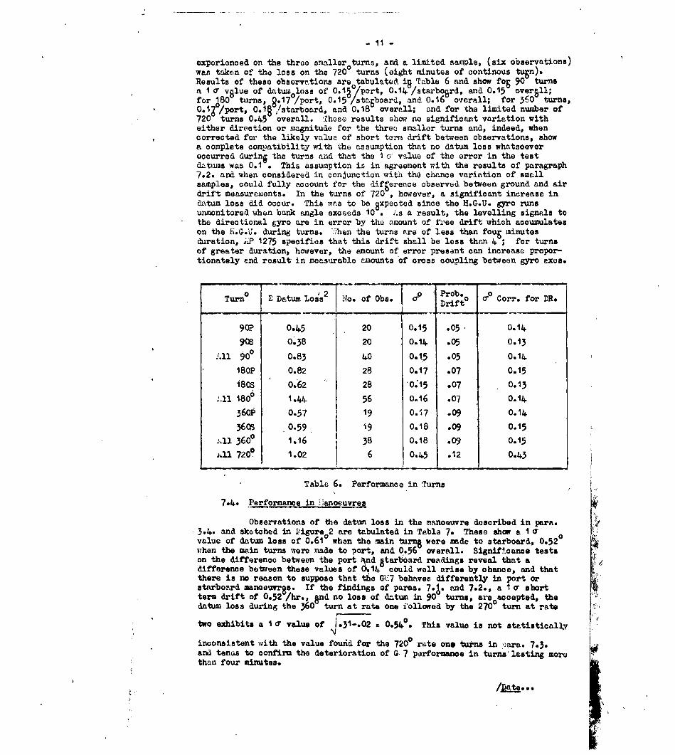
7.3. Performance in TurnsThe behaviour of the G)I7 in turns was investigated during turns of
90, 1800, 3600 and 7200. Statistical samples were taken of the datum loss
/experienced...
- 11 -
experienced on the three smaller turns, and a limited sample, (six observations)was taken of the loss on the 720 turns (eight minutes of continous tugn).Results of these observations are tabulated iR Table 6 and show fog 90 turnsa 1 a value of datumloss of' 0.1 0/port, 0.14 /starboerd, and O.5 oversll;for 180- turns, 8.17 /port, 0.15 /staboard, and 0.16 overall; for 360 turns,0.1/port, 0.19 /starboard, and 0.18 overall; and for the limited number of720 turns 0.45 overall. Those results show no significant variation witheither direction or magnitude for the three smaller turns and, indeed, whencorrected for the likely value of short term drift between observations, showa complete compatibility with the assumption that no datum loss whatsoeveroccurred durini the turns and that the I o value of the error In the testd-ttuns was 0.1 . This assumption is in agreement with the results of paragraph7.2. and when considered in conjunction with the chance variation of smallsamples, could fully account for the difference observed between ground and airdrift measurements. In the turns of 720 , however, a significant increase indatum loss did occur. This was to be 8xpected since the H.G.U. gyro runsunmonitored when bank angle exceeds 10 . s a result, the levelling signals tothe directional gyro are in error by the amount of free drift which accumulateson the H.G.U. during turns. :;hen the turns are of less than foug minutesduration, ;. 1275 specifies that this drift shall be less than 4 ; for turnsof greater duration, however, the amount of error present can increase propor-tionately and result in measurable a-,ounts of cross coupling between gyro axes.
0 Z Datum Los2 i'o of 2bs I Prob.Turn a o. of Obs. 0 o co Corr. for DR.Drift°
90P 0.45 20 0.15 .05 0.1490s 0.38 20 0.14 .05 o.3
All 90 0.83 40 0.1,5 .05 0.1418OP 0.82 28 0.17 .07 0.15
180S 0.62 28 0.15 .07 0.13
-ln 180 1.44 56 0.16 .07 0.1436oP 0.57 19 0.&7 .09 0.14
3608 0.59 i9 0.18 .09 o.15
1,11 360P 1.16 38 0.18 .09 o.15n1 7200 1.02 6 0.45 .12 0.43
Table 6. Performance in Turns
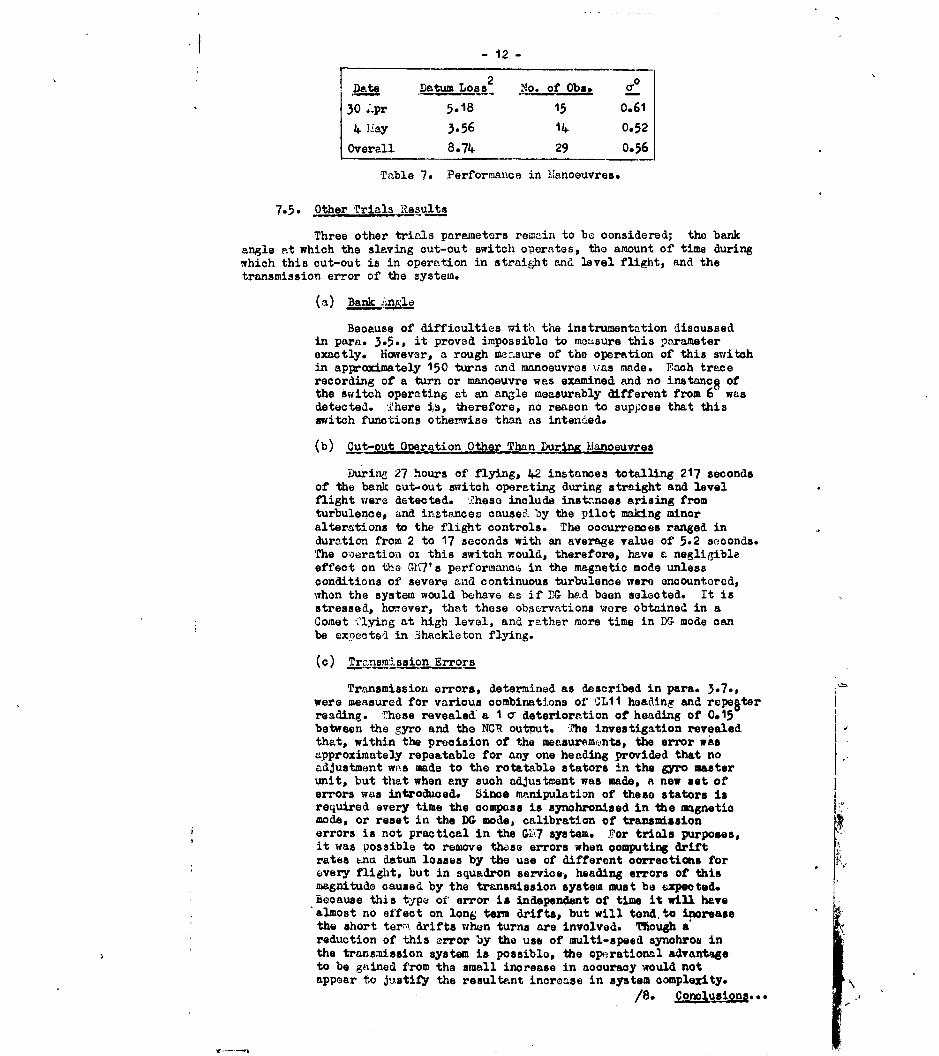
7.4. Performance in i anoeuvres
Observations of the datum loss in the manoeuvre described in para.3.4. and sketched in ligure0 2 are tabulated in Table 7. These show a i q 0 .
value of datum loss of 0.61 whern the main rn ere to starbod, 52when the main turns were made to port, and 0.56 overall. 8ignificance testson the difference between the port .%nd gtarboard readings reveal that adifference between these values of 6.114 could well arise by chance, and thatthere is no reason to suppose that the G'7 behaves differently in port orstarboard manoeuvres, If the findings of paras. 7-1. and 7.2., a I 0 shortterm drift of 0.52 /hr., gnd no loss of datum in 90 turns, are accepted, thedatum loss during the 360 turn at rate one followed by the 270 turn at rate
two exhibits a ic0 value of 431-.02 =0.54* This value is not statisticall
inconsistent with the value found for the 7200 rate one turns in ' ara. 7.-3.and tenus to confirm the deterioration of G 7 performanoe in turns' lasting morethan four minutes.
/lwt...
12 -
Date Datum Loss 2 No. of Obs.
30 Lpr 5.18 15 0.61
4 ";ay 3.56 14 0.52
Overall 8.74 29 0.56
Table 7. Performance in Manoeuvres.
7.5. Other Trials -1esults
Three other trials parameters remain to be considered; the bankangle at which the slaving cut-out switch operates, the amount of time duringwhich this cut-out is in operation in straight and level flight, and thetransmission error of the system.
(a) Bank angla
Because of difficulties with the instrumentation discussedin para. 3.5., it proved impossible to measure this parameterexactly. However, a rough a,.:asure of the operation of this switchin approximately 150 turns and manoeuvres ias made. Fach tracerecording of a turn or manoeuvre was examined and no instancS ofthe switch operating at an angle measurably different from 6 wasdetected. There is, therefore, no reason to suppose that thisswitch functions otherwise than as intended.
(b) Cut-out Operation Other Than Durin lianoeuvres
Durirn 27 hours of flying, 42 instances totalling 217 secondsof the bank cut-out switch operating during straight and levelflight were detected. These include instances arising fromturbulence, and instances caused by the pilot making minoralterations to the flight controls. The occurrences ranged induration from 2 to 17 seconds with an average value of 5.2 seconds.The o-oeration ox this switch would, therefore, have a negligibleeffect on the 7'es performance in the magnetic mode unlessconditions of severe and continuous turbulence were encountered,when the system would behave as if DG had been selected. It isstressed, ho-ever, that these obeervations wore obtained in aComet flying at high level, and rather more time in DG mode canbe expected in 3hackleton flying.
(c) Tr znsrission Errors
Transmission errors, determined as described in para. 3.7.,were measured for various combinations of CL11 heading and repeterreading. These revealed a I o- deterioration of heading of 0.15between the gyro and the NCR output. -7he investigation revealedthat, within the precision of the measuremints, the error wasapproximately repeatable for any one heading provided that noadjustment was made to the rotatable stators in the gyro masterunit, but that when any such adjustment was made, a new set oferrors was introduced. Since manipulation of these stators isrequired every time the compass is synohronised in the magnetiomode, or reset in the DG mode, calibration of transmissionerrors is not practical in the G17 system. For trials purposes,it was Possible to remove these errors when computing driftrates Pna datum losses by the use of different eorreotions for*every flight, but in squadron service, heading errors of thismagnitude caused by the transmission system must be expected.Because this type of error is independent of time it will havealmost no effect on long term drifts, but will tend. to increasethe short term drifts when turns are involved. Tough a°
reduction of this error by the use of multi-speed synohrob inthe transmission system is possible, the operational advantageto be gained from the small increase in accuracy would notappear to justify the resultant increase in system complexity.
/8. Conlus ... .

- 13 -
8. Conclusions
The results of the trial shw that the G 7 is a hih performance oompasssystem, capable of great pi.ecision in the DCT mode. They also reveal thenecessity for calibration of the Latitude Controller in order to obtain fulladvantage from the performance availeble. If this is done, the G±d7's longterm drift should be less than 0.3 0/hr., and its short term drift should notexceed 0.60/hr. (ia). Neither the long term drift nor the short term 6riftare affected to any ap reciable extent by normal fli-:ht or by turns of under4 minutes duration. ZJot only do such turns produce no detectable loss ofheading datum, but, in addition, long series of such turns have no significanteffect on the gyro's long term drift rate.
The only major wevacness of the system detected during the trials was its
susceptibility to cross coupling errors whenever the horizon inputs fromthe .G.U. were seriously in error. Errors from this source would not occugin normal flight, but only during periods of prolonged bank in excess of 10or in the event of a power failure such as that described in para. 6. In theformer case, the amount of error introduced is small but increases with theduration of the turn. Trials eroperience has shown that an error of about 0.5will be accumulated in a continuous turn of 8 minutes duration. ,n.y inter-ruption of the turn would, of course, reduce the error because of the re-ereotionfunction of the electrolytic levels in'the H.G.U., and, as a result, largeerrors from this source are unlikely to arise in operational conditions. Theeffect of partial power failures can, however, be much more serious. Suchfailures can reduce the rigidity of the vertical gyro to such an extent thatthe bank angle input to the L1l is grossly in error. !.fter a turn involvingthis type of failure, heading errors of tens of degrees can be experienced.i. total power failure to the H.G.U. on the other hand is less likely to causelarge errors since, in this case, the comparator circuit described in para. 2would imediately disengage the roll stabilisation mechanism. a further2robleia with the partial failure case is the difficulty in detecting such a,alfunction during a turn, since the pilot would not expect the 1l.G.U. to belevel in any event,' and the fact that it was indicating a larger or smallerdegree of bank than was actually in use would not be easily noticed. In acom;letely twinned system with separate H.G.U's, driven by independent powersupplies, controlling the roll rings of separate CI.1is any cross couplingerrors would immediately become apparent. However, in an installation likethe hackleton's the only immediate soluti n to the problem is to operate onlyone system in the DG mode at a time and to retain the other in the slaved modeas an assurance against gross errors.
9. Recommendations
Recommendations as to the most effective operation of the r 147 system andas to possible improvements are considered under four headings.-
(a) Operation of present system,
(b) The latitude controller,
(c) The horizon gyro unit, and
(d) The transmission system.
90. eration of -'resent Ss ter
From the trials results it is apparena that the precision availablefrom the present G'7 system in the I mode it of a hirth quality and that theaccuracy obtainable by operating in this mode compares more than favourablywith that of most magnetic systems. Three precautions are, however, necessaryto obtain optimum performance from the system:-
(a) , calibration graph must be prepared for the latitudecontroller end used in all DG operations;
/(b)...

- 14-
(b) here two systems are available, one should be left in theslaved mode at all times to ensure against gross errors resultingfrom faulty H.G.U. operation; and
(c) Continuous turns involving bank angles in excess of 100 forperiods in excess of 4 minutes should be avoided unless somedeterioration of performance is acceptable.
9.2. Latitude Jontroller
lthough, when properly calibrated, the present latitude controllercan eATectively eliminate earth rate drifts, its maximum compensation rate of15.04 /hr. restricts DG operations to the use of grid heading in many situations.Because true heading operation is more suitable for many purposes, it would bedesirable if the GH'7 could be operated in DG mode using a true heading referenceover a much larger portion of the earth. The difficulty with the presnetinstallation is that, to fly to a true reference using a directional gyro, acorrection for transpo:-t wander as well as earth rate is required which can bebegond the range of the controller. In aircraft flying east at 200 knots at70 N would, for example, require a comb'ined earth rate and transport wandercompensation rate of over 24 /hr. to maintUin a true heading in DG operation.: hether a particular user unit would require this facility or not would dependon its operational role, but it is certain that the operational flexibilityof users of the GA7 wo8 ld be increased if an alternate latitude controllerproviding for about 30 /hr. of drift compensation were available. If such acontroller mere provided with a dual scale, calibrated in both degrees latitudeand degrees pur hour of compensation, the navigator would be able to settransport rates directly without reference to tables or graphs, and would havemore time to attend to his more important duties.
9-3. Horizon q= Unit
The Z.G.U. can introduce errors into the system under two rlistinctsets of circumstances, either during turns of long duration when its own freedrift produces errors or by losing rigidity through a faulty po.;er supply.3rrrs from the first cause are not large and, if datum losses of the order of0.5 in 8 minutes continuous turning are acceptable then the present installationis quite adequate. If, however, turning errors of this magnitude are unaccept-able, the only simple solution that does not introduce other errors of evengreater magnitude is to replace the present vertioal gyro by one of considerablyless free drift. Tihe other and more serious problem of 3reventing large headingerrors during periods of faulty power supply is one of more comolexity. Thereoommendation of para. 9.i.(b) provides a method of detecting these errorswhere two systems are installed, but does nothing towards rectifying thesituation. It nay be that the rarity of such occurrences renders them opera-tionally acceptable, but if not, remedial action can take one of two forms; -
either redesigning the power supply to ensure that such failures do not occur,or arranging for automatic reversion to a secondary mode when they do.Engineering investigation would probably reveal a number of ways in which eitherof these goals could be met, such as duplicated power supnlies or automaticcut outs that function when the angular velocity of the H.G.UT. rotor fallsbelm a pm-determined value, but without oonsiderable experience on thefregquenoy of such oo'.urrences it is impossible to estimate the urgency of sucha modification.
9.4- Transmission Eistem
The performance of the system could be improved by the use of ivlti-speed synohros to reduce transmission errors. huch a modification would addlittle to the accuracy of the system in general navigation or in manoeuvrescarried out on a large scale, but would serve 1w reduce errors occurring in 4'close-in' tactical manoeuvres. It would not be required for all outputs, butwould be limited to the transmission train between the CLi itself, the compassmaster unit, and the aircraft's ground position computer. The synchrospresently installed seem quite adequate for other purposes.
/9.5.

-15-
9.5. Sumarjof Recommendations
The following is a summary of recommendations regarding the GH7arising from its trials in the DG mode at A. & ..
Recommendation TIr encX
(i) Calibration of latitude controller )-ssential for accurate DGoperation.
(ii) Retaining one system in magnetic Highly desirable - Guards againstmode at all times large undetected errors in event
of H.G.U. malfunction.
(iii) tvoiding continuous turns of more Desirable - i;rrors of about 0.50
than about 4. minutes duration. can occur in turns of 8 mins.duration.
(iv) 6ubstituting a new latitude cent- Advantageous - Improves flexibilityroller with provision for more of operation in high latitudes.than 15.01+ /hr. drift compensation.
(v) ;iodification of system to avoid Depends on frequency of occurrencelarge errors caused by faulty H.G.U. in operational aircraft.operation.
(vi) Substituting a higher performance Depends on aircraft role, veryvertical gyro for that in the H.G.U. advantageous for aircraft whose
role involves extensivemanoeuvring.
(vii) Provision of multi-speed synchros idvantageous, particularly forin heading drive to position com- 'close-in' manoeuvring.puters.
PREF71MCES
Ref. No. Author Titletc.
I Sperry Gyroscope Coo Design Specification"'o. D.6458.
2 A.P.1275B Volu se I Section 113 A.P.1275,- Volume I Section 13
CIRCULATION LIST
D.R.A.F.C. 1 CopyD.A. Nay. I "
A.D. Nav. 2 Copies 1 for ActionNav. 1(b) 1 CopyR.A.F.C.3 1
R.D.T.3 I
* T.I.L. 50 CopiesR.A.E. Farnborough 6 CopiesR.A.E. Bedford 2 Copies.
MOURLYFG.iRATC FI.
150
LATITUDCCONfTROL Cf
10
00 10 10'740 4 604Iw AT 440 OW * so
LATIUDE ONTRLLERCOMPENSA91TION
1P -,FIG. 2.
IafMLAa4D
'is
-3 4 t.68I IQCCK
PATTEN FLOW TO SIMUATE A TYPCAL T 1CAL. IOMORE(TWO MANOLKUVRES SHOWN

These abstract curts are Irnrted In Reports for the ocawevilence of Librarians and others ft~Ited to l miua an Intonation Incle:.
larc!
aI V
, :.oi,., ++ h.. ,+.
:++ 2 I i.t
to 0R , ,g v
~03
I ~ l +I:
.. i,-C cli of
A 3 a Joer
!I '+ jU - Iil, .c.
____ ____ ___ ____ _ ii~ri'I _ _ _ _ _ _ _ _

/ [dsttl
[dstl] P wu I'
S'P I!I(
Defense Technical Information Center (DTIC)8725 John J. Kingman Road, Suit 0944Fort Belvoir, VA 22060-6218U.S.A.
AD#: AD396368
Date of Search: 5 December 2008
Record Summary: AVIA 18/2114Title: Evaluation of Sperry GM7 Compass System in the Directional Gyroscope ModeAvailability Open Document, Open Description, Normal Closure before FOI Act: 30 yearsFormer reference (Department) AAEE/TECH 312/NHeld by The National Archives, Kew
This document is now available at the National Archives, Kew, Surrey, UnitedKingdom.
DTIC has checked the National Archives Catalogue website(http://www.nationalarchives.gov.uk) and found the document is available andreleasable to the public.
Access to UK public records is governed by statute, namely the PublicRecords Act, 1958, and the Public Records Act, 1967.The document has been released under the 30 year rule.(The vast majority of records selected for permanent preservation are madeavailable to the public when they are 30 years old. This is commonly referredto as the 30 year rule and was established by the Public Records Act of1967).
This document may be treated as UNLIMITED.