Austroads - Beaumaris Conservation Society Incbcs.asn.au/austroads_cycling.pdf · Austroads...
157
Austroads Cycling Aspects of Austroads Guides
Transcript of Austroads - Beaumaris Conservation Society Incbcs.asn.au/austroads_cycling.pdf · Austroads...

Austroads
ISBN 978-1-921709-60-9AP-G88-11 Cycling Aspects of Austroads Guides

Cycling Aspects of Austroads Guides

Cycling Aspects of Austroads Guides Summary
This report contains key information that relates to the planning, design and traffic management of cycling facilities and is sourced from Austroads Guides, primarily the Guide to Road Design, the Guide to Traffic Management and the Guide to Road Safety.
The report has been produced to ensure that information is readily available for practitioners who have a specific interest in cycling issues and facilities.
The report provides:
an overview of planning and traffic management considerations and cross-references to other Guides and texts for further detailed information
a summary of design guidance and criteria relating to on-road and off-road bicycle facilities together with a high level of cross-referencing to the relevant Austroads Guides for further information
information and cross-references on the provision for cyclists at structures, traffic control devices, construction and maintenance considerations and end of trip facilities. Keywords
Bicycle strategies, bicycle network, bicycle programs, public transport, activity centres, bicycle rider requirements, bicycle lanes, shoulders, unsignalised intersections, signalised intersections, roundabouts, interchanges, path crossings, structures, elements, head-start, storage, hook turn, refuge, traffic control, signs, pavement marking, surface, bicycle crossing lights, construction, maintenance, end of trip facilities, bicycle parking, evaluation, survey methods, safety audit. Published March 2011 © Austroads Ltd. 2011 This work is copyright. Apart from any use as permitted under the Copyright Act 1968, no part may be reproduced by any process without the prior written permission of Austroads. ISBN 978-1-921709-60-9 Austroads Project No. NP1436 Austroads Publication No. AP-G88/11 Project Manager
Duncan Elliott Prepared by
Gary Veith and Peter Eady Published by Austroads Ltd Level 9, Robell House 287 Elizabeth Street Sydney NSW 2000 Australia Phone: +61 2 9264 7088 Fax: +61 2 9264 1657 Email: [email protected] www.austroads.com.au

This Guide is produced by Austroads as a general guide. Its application is discretionary. Road authorities may vary their practice according to local circumstances and policies. Austroads believes this publication to be correct at the time of printing and does not accept responsibility for any consequences arising from the use of information herein. Readers should rely on their own skill and judgement to apply information to particular issues.


Cycling Aspects of Austroads Guides
Sydney 2011

Austroads profile Austroads’ purpose is to contribute to improved Australian and New Zealand transport outcomes by:
providing expert advice to SCOT and ATC on road and road transport issues facilitating collaboration between road agencies promoting harmonisation, consistency and uniformity in road and related operations undertaking strategic research on behalf of road agencies and communicating outcomes promoting improved and consistent practice by road agencies.
Austroads membership Austroads membership comprises the six state and two territory road transport and traffic authorities, the Commonwealth Department of Infrastructure and Transport, the Australian Local Government Association, and NZ Transport Agency. Austroads is governed by a Board consisting of the chief executive officer (or an alternative senior executive officer) of each of its eleven member organisations:
Roads and Traffic Authority New South Wales Roads Corporation Victoria Department of Transport and Main Roads Queensland Main Roads Western Australia Department for Transport, Energy and Infrastructure South Australia Department of Infrastructure, Energy and Resources Tasmania Department of Lands and Planning Northern Territory Department of Territory and Municipal Services Australian Capital Territory Commonwealth Department of Infrastructure and Transport Australian Local Government Association New Zealand Transport Agency. The success of Austroads is derived from the collaboration of member organisations and others in the road industry. It aims to be the Australasian leader in providing high quality information, advice and fostering research in the road sector.
Cycling Aspects of Austroads Guides
A u s t r o a d s 2 0 1 1
— i —
CONTENTS 1 INTRODUCTION ...................................................................................................................... 3 1.1 General ..................................................................................................................................... 3 1.2 Safe System Approach ............................................................................................................. 3
2 PLANNING AND TRAFFIC MANAGEMENT FOR CYCLISTS ............................................... 5 2.1 Role of Cycling in Transport ..................................................................................................... 5 2.2 Bicycle Strategies and Strategic Bicycle Plans ......................................................................... 5
2.2.1 National Cycling Strategy .......................................................................................... 5 2.2.2 State or Territory Bicycle Strategy ............................................................................. 6 2.2.3 Local Strategic Bicycle Plan ...................................................................................... 7
2.3 Bicycle Network Management .................................................................................................. 7 2.3.1 Introduction ................................................................................................................ 7 2.3.2 Purpose of a Bicycle Network .................................................................................... 7 2.3.3 Functions of a Bicycle Network .................................................................................. 7 2.3.4 Objectives of a Bicycle Network ................................................................................ 8 2.3.5 Network and Route Mapping ..................................................................................... 8 2.3.6 Categories of Cyclists and their Network Requirements............................................ 9
2.4 Bicycle Programs ...................................................................................................................... 9 2.4.1 Behavioural Aspects Programs ............................................................................... 10 2.4.2 Traffic Studies and Bicycle Surveys ........................................................................ 11
2.5 Type of Bicycle Facility Required ............................................................................................ 12 2.6 Combining Bicycle Travel with Public Transport ..................................................................... 13 2.7 Integrated Land Use/Bicycle Planning .................................................................................... 14 2.8 Local Area Traffic Management .............................................................................................. 14 2.9 Traffic Management in Activity Centres .................................................................................. 16
2.9.1 Planning Context for Cycling in Activity Centres ...................................................... 16 2.9.2 Bicycles in Activity Centres ...................................................................................... 18
2.10 Traffic Impacts of Developments ............................................................................................ 18
3 BICYCLE RIDER REQUIREMENTS ...................................................................................... 19 3.1 General ................................................................................................................................... 19 3.2 Space to Ride ......................................................................................................................... 19 3.3 Smooth Surface ...................................................................................................................... 20 3.4 Speed Maintenance ................................................................................................................ 20 3.5 Sight Lines .............................................................................................................................. 21 3.6 Connectivity ............................................................................................................................ 21 3.7 Information .............................................................................................................................. 22
4 BICYCLE FACILITIES ON ROAD (MID-BLOCK) ................................................................. 23 4.1 General ................................................................................................................................... 23 4.2 Provision for Cyclists on Roads .............................................................................................. 24
4.2.1 General .................................................................................................................... 24 4.2.2 Exclusive Bicycle Lanes .......................................................................................... 24 4.2.3 Wide Kerbside Lanes ............................................................................................... 26 4.2.4 Sealed Shoulders .................................................................................................... 28 4.2.5 Bus/Bicycle Lanes ................................................................................................... 28 4.2.6 Advisory Treatments ................................................................................................ 29
4.3 Types of Bicycle Lane Treatments ......................................................................................... 29 4.3.1 Bicycle/Car Parking Lanes ....................................................................................... 29 4.3.2 Contra-flow Bicycle Lanes ....................................................................................... 32

Cycling Aspects of Austroads Guides
A u s t r o a d s 2 0 1 1
— ii —
4.3.3 Separated Bicycle Lanes ......................................................................................... 32 4.3.4 ‘Peak Period’ Bicycle Lanes .................................................................................... 35 4.3.5 Protected Two-way lanes ........................................................................................ 36
4.4 Finding Space for Bicycle Lane Treatments ........................................................................... 36 4.5 Supplementary Road Treatments ........................................................................................... 37
4.5.1 Curves and Turns .................................................................................................... 37 4.5.2 Lane Channelisation ................................................................................................ 38
4.6 Ramps .................................................................................................................................... 38 4.7 Road Safety Barriers .............................................................................................................. 40 4.8 Provision for Cyclists on Freeways ......................................................................................... 41
4.8.1 General .................................................................................................................... 41 4.9 Local Area Traffic Management Schemes .............................................................................. 42
5 ROAD INTERSECTIONS ....................................................................................................... 46 5.1 Introduction ............................................................................................................................. 46 5.2 Issues at Intersections for Cyclists ......................................................................................... 46
5.2.1 General .................................................................................................................... 46 5.3 Signalised Road Intersections ................................................................................................ 48
5.3.1 General .................................................................................................................... 48 5.3.2 Traffic Management Guidelines ............................................................................... 48 5.3.3 The Six Elements ..................................................................................................... 50 5.3.4 Bicycle Lanes ........................................................................................................... 54 5.3.5 Head-start and Expanded Storage Areas ................................................................ 55 5.3.6 Hook Turn Storage Boxes and Hook Turn Restrictions ........................................... 57 5.3.7 Left-turn Treatments ................................................................................................ 58 5.3.8 Bypass of T-intersection .......................................................................................... 60 5.3.9 Crossings at Signalised Intersections ...................................................................... 61 5.3.10 Signalised Mid-block Crossings ............................................................................... 63
5.4 Unsignalised Road Intersections ............................................................................................ 64 5.4.1 General .................................................................................................................... 64 5.4.2 Basic and Channelised Intersections ....................................................................... 65 5.4.3 Channelised Left-turn Treatment ............................................................................. 67 5.4.4 Refuge within an Unsignalised Intersection ............................................................. 68
5.5 Roundabouts .......................................................................................................................... 69 5.5.1 Introduction .............................................................................................................. 69 5.5.2 Local Roads – No Bicycle Facility ............................................................................ 72 5.5.3 Bicycle Lanes at Single-lane Roundabouts ............................................................. 73 5.5.4 Multi-lane Roundabouts on Arterial Roads .............................................................. 76 5.5.5 Bicycle Paths and Shared Paths at Roundabouts ................................................... 78
5.6 Interchanges ........................................................................................................................... 79 5.6.1 General .................................................................................................................... 79 5.6.2 At-grade Treatment at Interchanges ........................................................................ 79 5.6.3 Grade Separation of Ramps for Cyclists ................................................................. 81 5.6.4 Alternative Routes ................................................................................................... 81
6 RAILWAY CROSSINGS ........................................................................................................ 82 6.1 Path Crossings ....................................................................................................................... 82 6.2 Railway Level Crossings ......................................................................................................... 83
7 PATHS .................................................................................................................................... 84 7.1 General ................................................................................................................................... 84 7.2 Types of Path .......................................................................................................................... 84 7.3 Choice of Appropriate Type of Path ........................................................................................ 85
Cycling Aspects of Austroads Guides
A u s t r o a d s 2 0 1 1
— iii —
7.4 Location of Paths for Cycling .................................................................................................. 85 7.5 Path Design Criteria for Bicycles ............................................................................................ 86
7.5.1 General .................................................................................................................... 86 7.5.2 Bicycle Operating Speed ......................................................................................... 86 7.5.3 Horizontal Alignment ................................................................................................ 86 7.5.4 Width ........................................................................................................................ 87 7.5.5 Vertical Alignment .................................................................................................... 89 7.5.6 Crossfall and Drainage ............................................................................................ 90 7.5.7 Clearances, Batters and Fences ............................................................................. 91 7.5.8 Sight Distance .......................................................................................................... 92
7.6 Path Crossings of Roads ........................................................................................................ 95 7.6.1 General .................................................................................................................... 95 7.6.2 Bicycle Path Crossing .............................................................................................. 96 7.6.3 Refuges for Path Crossings away from Intersections .............................................. 98 7.6.4 Cyclist Priority Treatment at Bicycle Path Crossings of Low-volume Streets .......... 99 7.6.5 Path Crossings of Side Roads ............................................................................... 100 7.6.6 Path Approach Design Criteria .............................................................................. 100 7.6.7 Types of Crossings of Side Roads ........................................................................ 100
7.7 Intersections of Paths with Paths .......................................................................................... 106 7.8 Path Terminal Treatments .................................................................................................... 106 7.9 Fences and Road Safety Barriers ......................................................................................... 108 7.10 Road and Path Lighting ........................................................................................................ 108
8 PROVISON AT STRUCTURES ........................................................................................... 109 9 TRAFFIC CONTROL DEVICES ........................................................................................... 110 9.1 Signs ..................................................................................................................................... 110 9.2 Pavement Markings .............................................................................................................. 110
9.2.1 Roads .................................................................................................................... 110 9.2.2 Paths ...................................................................................................................... 111
9.3 Pavement Surface Colour ..................................................................................................... 111 9.4 Bicycle Crossing Lights ......................................................................................................... 112
9.4.1 Bicycle Aspects ...................................................................................................... 112 9.4.2 Bicycle Detection ................................................................................................... 113
10 CONSTRUCTION AND MAINTENANCE ............................................................................ 114 10.1 General ................................................................................................................................. 114
11 END OF TRIP FACILITIES .................................................................................................. 115 11.1 General ................................................................................................................................. 115 11.2 Showers, Lockers and Security ............................................................................................ 115 11.3 Bicycle Parking ..................................................................................................................... 115
REFERENCES .............................................................................................................................. 116 APPENDIX A BICYCLE NETWORK EVALUATION EXAMPLE .................................... 119 APPENDIX B BICYCLE SURVEY METHODS ............................................................... 123 APPENDIX C HUMAN POWERED VEHICLES .............................................................. 125 APPENDIX D BICYCLE SAFETY AUDIT CHECKLIST ................................................. 126 APPENDIX E EXAMPLE OF BICYCLE SAFETY AUDIT ............................................... 132 APPENDIX F BICYCLE PARKING REQUIREMENTS ................................................... 135

Cycling Aspects of Austroads Guides
A u s t r o a d s 2 0 1 1
— iv —
TABLES Table 2.1: Bicycle network features ............................................................................................. 7 Table 2.2: Bicycle network functions ........................................................................................... 8 Table 2.3: Categories of cyclists and their characteristics ........................................................... 9 Table 2.4: Use, advantages and disadvantages of bicycle lanes, advisory
treatments and bypasses in LATM schemes ............................................................ 15 Table 2.5: Example of guiding principles and criteria for bicycle plans ..................................... 17 Table 4.1: Exclusive bicycle lane dimensions in urban areas .................................................... 26 Table 4.2: Wide kerbside lane dimensions ................................................................................ 27 Table 4.3: Width of kerbside bus lanes ...................................................................................... 29 Table 4.4: Bicycle/car parking lane dimensions (parallel parking) ............................................. 30 Table 4.5: Bicycle/car parking lane dimensions (angle parking) ................................................ 31 Table 4.6: Considerations in the design of kerb separated bicycle lanes .................................. 34 Table 4.7: Cyclist use of freeways – factors to consider ............................................................ 41 Table 4.8: Factors to consider for cycling in regards to LATM schemes ................................... 43 Table 5.1: Issues for cyclists ...................................................................................................... 47 Table 5.2: Cyclist requirements for arterial road signalised approaches ................................... 49 Table 5.3: Cyclist requirements for local road signalised approaches ....................................... 50 Table 5.4: Lane management at signalised intersections .......................................................... 50 Table 5.5: Summary of use of the head-start treatments illustrated in Figure 5.5 ..................... 56 Table 7.1: Cross-references for path key design criteria ........................................................... 86 Table 7.2: Minimum radii of horizontal curves without superelevation ....................................... 87 Table 7.3: Minimum radius of horizontal curves that have superelevation ................................ 87 Table 7.4: Bicycle path widths ................................................................................................... 88 Table 7.5: Shared path widths ................................................................................................... 88 Table 7.6: Separated two-way path widths ................................................................................ 89 Table 7.7: Separated one-way path widths ............................................................................... 89
FIGURES
Figure 2.1: Separation of cyclists and motor vehicles by speed and volume ............................. 13 Figure 2.2: Bicycle lane example ................................................................................................ 14 Figure 2.3: Examples of bicycle bypasses of LATM devices ...................................................... 15 Figure 3.1: Cyclist envelope ........................................................................................................ 20 Figure 4.1: An example of an exclusive bicycle lane .................................................................. 25 Figure 4.2: Wide kerbside lane ................................................................................................... 27 Figure 4.3: Typical bicycle/car parking lanes layout (parallel parking) ........................................ 30 Figure 4.4: Typical bicycle/car parking lanes layout (angle parking)........................................... 31 Figure 4.5: Contra-flow bicycle lane – layout .............................................................................. 32 Figure 4.6: Location and typical cross-section of kerb separated bicycle lane ........................... 33 Figure 4.7: Kerb separated bicycle lane ..................................................................................... 34 Figure 4.8: Typical cross-section of a separated protected bicycle lane..................................... 35 Figure 4.9: Peak period bicycle lane (i.e. during and outside clearway times) ........................... 36 Figure 4.10: Low and high-speed exit and entry ramps ................................................................ 39 Figure 4.11: Example of good practice – cycle bypass of a road hump ....................................... 44 Figure 4.12: Parked vehicle blocks cycle bypass ......................................................................... 44 Figure 4.13: Cycle bypass at half road closure ............................................................................. 45 Figure 5.1: Provision of a bicycle operating space at intersections – the six elements .............. 50

Cycling Aspects of Austroads Guides
A u s t r o a d s 2 0 1 1
— v —
Figure 5.2: Design options for signalised intersections (mid-block, transition and approach) .................................................................................................................. 52
Figure 5.3: Design options for signalised intersections (waiting, through and departure) ................................................................................................................. 53
Figure 5.4: Bicycle lanes through signalised intersections – car side and kerbside ................... 54 Figure 5.5: Head-start and expanded storage areas .................................................................. 55 Figure 5.6: Bicycle hook turn box detail ...................................................................................... 58 Figure 5.7: Provision for cyclists at a signalised CHL treatment in a low-speed
environment .............................................................................................................. 59 Figure 5.8: Bicycle lane left-turn bypass at a signalised intersection .......................................... 60 Figure 5.9: Cyclist bypass lane at a signalised T-intersection .................................................... 61 Figure 5.10: Shared path and two-way bicycle path at a signalised intersection .......................... 62 Figure 5.11: Right turn from an off-road bicycle path to an on-road bicycle lane .......................... 63 Figure 5.12: Signalised crossing with separate pedestrian and cyclist areas ............................... 64 Figure 5.13: Urban basic (BA) intersection turn treatments .......................................................... 65 Figure 5.14: Urban channelised (CH) intersection turn treatments ............................................... 66 Figure 5.15: Provision for cyclists at an unsignalised CHL treatment in a low-speed
environment .............................................................................................................. 67 Figure 5.16: An example of provision for cyclists at rural free-flow left-turn treatments ................ 68 Figure 5.17: Refuge within an intersection for pedestrians and cyclists in bicycle
lanes ......................................................................................................................... 69 Figure 5.18: Roundabout at a T-intersection – path connecting bicycle lanes ............................. 71 Figure 5.19: Bicycle lane continuing past a left-turn slip lane at a roundabout ............................. 72 Figure 5.20: Bicycle route through a single-lane roundabout – no bicycle facility......................... 73 Figure 5.21: Bicycle lane at a small single-lane roundabout on a local road ................................ 74 Figure 5.22: Two bicycle routes crossing at a single-lane roundabout with physically
separated bicycle lanes ............................................................................................ 75 Figure 5.23: Two bicycle routes crossing at a single-lane roundabout with no physical
separation of bicycle lanes ....................................................................................... 76 Figure 5.24: Bicycle lanes at a two-lane roundabout with physical separation for
cyclists ...................................................................................................................... 77 Figure 5.25: Details of an island on a multi-lane roundabout entry to separate cyclists
and motorists ............................................................................................................ 77 Figure 5.26: Details of an island on a multi-lane roundabout exit to separate cyclists
and motorists ............................................................................................................ 78 Figure 5.27: Path at a roundabout where cyclist and pedestrian volumes are low to
moderate ................................................................................................................... 78 Figure 5.28: Crossing detail for a shared path adjacent to a multi-lane roundabout .................... 79 Figure 5.29: Typical at-grade treatment for cyclists at exit and entry ramps ................................ 80 Figure 6.1: Examples of signs used at pedestrian and cyclist crossings of railways .................. 82 Figure 7.1: Guide to the choice of path treatment for cyclists ..................................................... 85 Figure 7.2: Desirable uphill gradients for ease of cycling ........................................................... 90 Figure 7.3: Minimum stopping sight distance for cyclists ............................................................ 93 Figure 7.4: Lateral clearances on horizontal curves ................................................................... 94 Figure 7.5: Minimum length of crest vertical curves .................................................................... 95 Figure 7.6: Bicycle path crossing of a two-way two-lane road and separated paths .................. 97 Figure 7.7: Example of a cyclist and pedestrian refuge at a mid-block location ......................... 98 Figure 7.8: Cyclist priority treatment for use at low-volume street crossing ................................ 99 Figure 7.9: Bicycle path crossing bent-out at side road ............................................................ 102 Figure 7.10: Bicycle path crossing (not bent-out at side road) .................................................... 103 Figure 7.11: One-way bicycle path crossing (bent-in side road) ................................................. 105 Figure 7.12: Separate entry and exit terminal ............................................................................. 107 Figure 7.13: Example of a bollard treatment ............................................................................... 107

Cycling Aspects of Austroads Guides
A u s t r o a d s 2 0 1 1
— vi —
Figure 7.14: Staggered fence treatment ..................................................................................... 108 Figure 9.1: Example of bicycle lane markings .......................................................................... 111 Figure 9.2: Bicycle signal aspect .............................................................................................. 112

Cycling Aspects of Austroads Guides
A u s t r o a d s 2 0 1 1
— 1 —
SUMMARY
This report contains key information that relates to the planning, design and traffic management of cycling facilities and is sourced from Austroads Guides, primarily the Guide to Road Design, the Guide to Traffic Management and the Guide to Road Safety.
The report has been produced to ensure that key information is readily available for practitioners who have a specific interest in cycling issues and facilities. However, users of the report should be aware that:
The design guidance is summarised for the convenience of practitioners and reference may have to be made to the relevant Austroads Guide for important details relating to particular topics or situations. Consequently this report provides a high level of cross-referencing to Austroads Guides.
It is highly recommended that practitioners who are less experienced in the planning and design of bicycle facilities refer to the original Austroads Guides.
Whilst the report provides an overview of planning and traffic management considerations, practitioners will need to refer to other Guides and texts for detailed information on these subject areas, some of which are referenced in the Austroads Guides.

Cycling Aspects of Austroads Guides
A u s t r o a d s 2 0 1 1
— 2 —

Cycling Aspects of Austroads Guides
A u s t r o a d s 2 0 1 1
— 3 —
1 INTRODUCTION
1.1 General This document is intended as a guide for engineers, planners and designers involved in the planning, design and construction of cycling facilities. It consolidates and summarises the information in current Austroads Guides, in particular the Guide to Road Design and the Guide to Traffic Management, so that the information on bicycle facilities is readily available for persons with a particular interest in the topic. Throughout the document practitioners are referred to relevant Austroads Guides for additional information.
The Guide to Road Design – Part 6A: Pedestrian and Cyclist Paths (Austroads 2009m) should be used for guidance on the planning, design and construction of paths. This document consolidates information relating to on-road bicycle facilities and provides a summary of key design information for cyclist paths, including intersections of paths with roads.
Designers should use the guidelines to support national and state cycling strategies (Section 2.2) so that communities can obtain environmental, health and transport benefits that are derived from increased cycling and walking. Cycling can be encouraged by the provision of bicycle access into and through all new land developments, the provision of treatments that assist bicycle travel and the provision of satisfactory showers and secure parking facilities in the workplace. Some information on end of trip facilities is also provided.
Cycling should be considered in all road planning, design, construction and maintenance activities. It should also be understood that cyclists basically need a smooth hazard-free riding environment and, where they share roads, they need sufficient space to operate safely alongside motor vehicles. As far as practicable, roadsides and roadside objects should also be designed to provide a forgiving environment for errant bicycles (e.g. the surface provided on a shoulder or berm should not trap bicycle tyres).
As bicycle riders include people with a very wide range of skills and ages (from novices to experts), and also people who travel for a variety of reasons, it is essential to cater for them even though this may result in more than one type of bicycle facility along a given route (Section 2.5).
1.2 Safe System Approach In Australia, a Safe System approach to road safety has been adopted which recognises that humans, as road users are fallible and will continue to make mistakes, and that the community should not penalise people with death or serious injury when they do make mistakes. In a Safe System, therefore, roads (and vehicles) should be designed to reduce the incidence and severity of crashes when they occur. The Safe System approach requires, in part (Australian Transport Council 2006):
designing, constructing and maintaining a road system (roads, vehicles and operating requirements) so that forces on the human body generated in crashes are generally less than those resulting in fatal or debilitating injury
improving roads and roadsides to reduce the risk of crashes and minimise harm: measures for higher-speed roads including dividing traffic, designing ‘forgiving’ roadsides, and providing clear driver guidance. In areas with large numbers of vulnerable road users or substantial collision risk, speed management supplemented by road and roadside treatments is a key strategy for limiting crashes
managing speeds, taking into account the risks on different parts of the road system.

Cycling Aspects of Austroads Guides
A u s t r o a d s 2 0 1 1
— 4 —
In New Zealand, practical steps have been taken to give effect to similar guiding principles through a Safety Management Systems (SMS) approach.
Road designers should be aware of and through the design process actively support the philosophy and road safety objectives covered in the Guide to Road Safety (Austroads 2006 – 2009). The philosophy and objectives are as relevant to pedestrian and cyclists paths as they are to roads in general.

Cycling Aspects of Austroads Guides
A u s t r o a d s 2 0 1 1
— 5 —
2 PLANNING AND TRAFFIC MANAGEMENT FOR CYCLISTS
2.1 Role of Cycling in Transport Cycling currently fulfils an important transport role within communities. Surveys conducted in major Australian cities have shown that cycling is popular and is increasing in popularity as a means of transport and for recreation.
The efficient transportation of people and goods in cities is essential if the economic and social needs of society are to be met. Whilst the private motor car is the favoured mode (by the community at large) for most trips in cities it has undesirable aspects in relation to traffic congestion, road safety, noise, and air pollution. Modes of transport which could play a greater role in offsetting these issues include walking, cycling, trains, trams and buses.
Cycling is a clean and efficient mode of transport that is well suited to many of the trips currently made in cars, particularly in inner urban areas. Many car trips, including travel to work, are less than 10 kilometres, a distance that can be covered in many inner urban areas as quickly on a bicycle as in a car.
Cycling offers significant environmental and health benefits for communities and must therefore be considered in all planning activities ranging from the development of cities and new towns to relatively small infrastructure developments. The recognition of cyclist needs will ensure that current planning decisions do not limit the ability of responsible authorities to provide satisfactory networks and facilities for bicycle riders in the future.
2.2 Bicycle Strategies and Strategic Bicycle Plans The main goal of bicycle planning is to encourage cycling as a desirable alternative to motor vehicle travel and to provide community and government programs which will provide for safe and convenient travel by bicycle.
The development of strategies is important because they provide a framework and direction for the development and coordination of programs throughout government and should constitute a commitment to various initiatives and actions. They also provide for the integration of cyclist needs into all planning and design activities including commercial and industrial building designs, land development plans, subdivision plans, road designs and road maintenance programs.
Therefore bicycle planning needs to include:
development of broad bicycle policies and bicycle strategies at both national and state levels which includes all aspects of cycling, involves all relevant departments and municipalities, and assigns responsibilities
development of local strategic bicycle plans on a municipal basis which set local strategies and defines local bicycle networks in relation to the principal or regional bicycle network (if one exists). These plans should also identify local needs for programs, and for road and path improvements.
These strategies and plans provide a statement of actions which are based, although not necessarily rigidly, on encouragement, education, engineering and enforcement.
2.2.1 National Cycling Strategy
The Australian National Cycling Strategy 2011-2016 (Austroads 2010) is a strategic document with a vision to double the number of people cycling over the life of the strategy so that individuals and

Cycling Aspects of Austroads Guides
A u s t r o a d s 2 0 1 1
— 6 —
communities can enjoy the benefits of cycling (e.g. those relating to urban space and traffic congestion, the environment and health). The strategy includes six priorities and associated objectives that are needed to drive progress at the national level, namely:
1. Cycling promotion – Promote cycling as a viable and safe mode of transport and an enjoyable recreational activity.
2. Infrastructure and facilities – Create a comprehensive and attractive network of routes to cycle and end-of-trip facilities.
3. Integrated planning – Consider and address cycling in all relevant transport and land-use planning activities.
4. Safety – Enable people to cycle safely.
5. Monitoring and evaluation – Improve monitoring and evaluation of cycling programs and develop a national decision-making process for investment in cycling.
6. Guidance and best practice – Develop nationally consistent guidance for stakeholders to use and share best practice across jurisdictions.
The national strategy in New Zealand is Getting there – on foot, by cycle: A strategy to advance walking and cycling in New Zealand transport (New Zealand Ministry of Transport 2005). This strategy aims to ensure that supportive walking and cycling environments are provided in New Zealand communities, that safety is improved for pedestrians and cyclists, and that people walk and cycle more as part of their day-to-day transport mix. A related document is Getting there – on foot, by cycle: Strategic implementation plan 2006 – 2009 (New Zealand Ministry of Transport 2006). It provides ten action items across the following four focus areas:
1. Strengthening foundations for effective action
2. Providing supportive environments and systems
3. Influencing individual travel choices
4. Improving safety and security.
The development of walking and cycling is integral to achieving the five transport targets within The New Zealand Transport Strategy (2008) which comprise:
Ensuring environmental sustainability.
Assisting economic development.
Assisting safety and personal security.
Improving access and mobility.
Protecting and promoting public health.
2.2.2 State or Territory Bicycle Strategy
State or territory strategies on cycling are necessary to set a direction and provide a framework within which various responsible agencies can plan and work. They also specify important strategic action areas and items and nominate responsible ‘lead agencies'. More information on these strategies is provided in Commentary 1.

Cycling Aspects of Austroads Guides
A u s t r o a d s 2 0 1 1
— 7 —
2.2.3 Local Strategic Bicycle Plan
Local strategic bicycle plans can be developed on a municipal basis or a regional basis where a number of municipalities share resources. The purpose of these plans is to translate many of the aims of the state-wide strategy into practical programs and projects at the local level.
Local strategic bicycle plans should, however, concentrate on the development of solutions to problems that exist within the municipality or region rather than deal with general issues. Information on the aims of local strategic bicycle plans is provided in Commentary 2.
2.3 Bicycle Network Management 2.3.1 Introduction
This section is based on the Guide to Traffic Management – Part 4: Network Management (Section 4.6, Austroads 2009b) which covers traffic management at a network level. It addresses network needs of the various categories of user (including cyclists), the characteristics of various types of network and, importantly, describes a planning process for balancing or prioritising the competing needs of different users. The information in this section is sourced from Austroads (2009b).
2.3.2 Purpose of a Bicycle Network
The purpose of a bicycle network is to enable cyclists of a wide range of abilities and experience to move safely and conveniently to chosen destinations via suitable desire lines. The basis of a bicycle network is the road network, augmented by special on-road facilities together with dedicated infrastructure such as off-road paths, and footpaths where permitted, and may include public transport. Table 2.1 details features that are important to form a good bicycle network.
Table 2.1: Bicycle network features
Route feature Comments
Safety Minimal risk of traffic-related injury, low perceived danger, space to ride, minimum conflict with vehicles.
Coherence Infrastructure should form a coherent entity, link major trip origins and destinations, have connectivity, be continuous, signed, consistent in quality, easy to follow, and have route options.
Directness Route should be direct, based on desire lines, have low delay through routes for commuting, avoid detours and have efficient operating speeds.
Attractiveness Lighting, personal safety, aesthetics, integration with surrounding area, access to different activities.
Comfort Smooth skid-resistant riding surface, gentle gradients, avoid complicated manoeuvres, reduced need to stop, minimum obstruction from vehicles.
Source: Table 4.11 of Austroads (2009b).
2.3.3 Functions of a Bicycle Network
There should be a relationship between the functions of the component parts of a bicycle network and the functions of the road network hierarchy. Where bicycle routes run along or cross the road network, the operational facilities should reflect the network functions for both the road and the bicycle route cycleway. Table 2.2 relates the bicycle network hierarchy to the purpose for which it will be used.

Cycling Aspects of Austroads Guides
A u s t r o a d s 2 0 1 1
— 8 —
Table 2.2: Bicycle network functions
Network Network function Cyclist operating speed
Regional bicycle network (1) High-quality, high-priority routes to permit quick, unhindered travel between the major regions of cities, towns or urban areas.
25 – 40 km/h
Local bicycle routes High-quality routes with seamless connections to regional routes. These routes connect the local street system to the major regional routes.
20 – 30 km/h
Mixed traffic streets (door to door access to all destinations)
Low speed, low volume local access to residential destinations in ‘low -stress’ shared environments.
< 20 km/h
1 Principal bicycle network in some jurisdictions.
Source: Table 4.13 of Austroads (2009b). Adapted from RTA (2005).
2.3.4 Objectives of a Bicycle Network
The purpose of a bicycle network is to encourage new cycling trips and increase the safety and convenience of existing cycling trips. The objectives outlined in the Guide to Traffic Management – Part 4: Network Management (Section 4.6.4, Austroads 2009b) that are relevant to the planning, design and operation of bicycle networks include:
a designated regional network of roads and paths that serves longer-distance commuter and recreational trips
designated local networks and routes designed to provide low-stress routes, to feed the regional network and to provide for shorter local trips to shopping centres, recreational activities, public transport hubs
full construction of route sections between origins and destinations consistent with the route purpose
convenient access into and through residential, commercial and industrial subdivisions, and major developments
access and facilities to travel with a bicycle on public transport
secure long and short-term parking facilities at major destinations
safe routes to schools
well-defined bicycle facilities on arterial roads where significant cyclist demand exists including specifically for commuter trips
appropriate maintenance practices which result in smooth surfaces
calming in local streets
paths which are interesting, that include rest areas at appropriate intervals on regional routes, and are designed to appropriate geometric standards
implementation of regulatory, warning and guidance signage on paths.
2.3.5 Network and Route Mapping
As with any transport system, accurate and comprehensive information concerning the bicycle network is essential. Maps should be available to cyclists showing the route, facilities and points of interest including the relationship to the surrounding road system and community facilities. The scope of bicycle route and network maps can be local or regional but should always adopt a network approach and aim to present through routes and access locations.

Cycling Aspects of Austroads Guides
A u s t r o a d s 2 0 1 1
— 9 —
2.3.6 Categories of Cyclists and their Network Requirements
Cyclists are diverse in their needs and may fulfil a number of needs on a single trip. Seven groups of cyclists have been identified, each with specific riding characteristics and network requirements (Section 4.6.2, Austroads 2009b). There is usually a need to cater for more than one group in any corridor. The groups are discussed in Table 2.3.
Table 2.3: Categories of cyclists and their characteristics
Category Rider characteristics Riding environment
Primary school children Cognitive skills not developed, little knowledge of road rules, require supervision.
Off-road path, footpath (where permitted) or very low volume residential street.
Secondary school children
Skill varies, developing confidence. Generally use on-road facilities or off-road paths where available.
Recreational Experience, age, skills vary greatly. Desire off-road paths and quiet local streets, avoid heavily trafficked routes, more experienced will prefer to use road system for long journeys.
Commuter Vary in age, skill and fitness, some highly skilled and able to handle a variety of traffic conditions.
Some prefer paths or low-stress roads, willing to take longer to get to destination, others want quick trips regardless of traffic conditions, primarily require space to ride and smooth riding surface, speed maintenance.
Utility Ride for specific purposes (shopping), short length trips, routes unpredictable.
Not on highly trafficked roads, needs include comprehensive, low-stress routes, appropriate end of trip facilities.
Touring Long distance journeys, may be heavily equipped, some travelling in groups.
Often route is similar to that of other tourists.
Sporting Often in groups, two abreast occupying left lane, needs similar to commuters.
Travel long distances in training on arterials, may include challenging terrain in outer urban or rural areas, generally do not use off-road routes because of high speed and conflict with other users.
Source: Table 4.12 of Austroads (2009b).
2.4 Bicycle Programs Bicycle programs are concerned with both transport network improvements and behavioural issues. The objective is to make cycling safer, more convenient and hence an attractive alternative means of transport. Programs generally address issues relating to education, encouragement, enforcement and engineering but these 4 Es should usually be regarded as inter-related components of the same program, rather than separate programs. For example, as a network of bicycle routes is developed within a city or town (Engineering) it will be necessary to:
promote it through advertising, pamphlets and maps (Encouragement)
teach people who use it how to ride safely and courteously (Education)
insist that relevant laws and regulations be obeyed for the benefit of all users (Enforcement).
An example of a bicycle network evaluation from the Guide to Project Evaluation – Part 8: Examples (Austroads 2006) can be found in Appendix A.

Cycling Aspects of Austroads Guides
A u s t r o a d s 2 0 1 1
— 10 —
2.4.1 Behavioural Aspects Programs
Bicycle programs will include consideration of many issues relating to the behaviour of cyclists, their safe use of the transport network, and the encouragement of cycling. Sub-programs should be developed to address these issues and initiatives that might be taken are listed below. Whilst many of the initiatives are inter-related, for convenience they are divided into Education, Enforcement and Encouragement.
Education programs
Initiatives relating to the education of the community regarding cycling may include:
bicycle safety education programs in primary schools
bicycle safety education programs in secondary schools including development of on-road skills
courses for inexperienced adult cyclists
development of a cyclist code of behaviour
ongoing education of motorists and cyclists to better understand each others needs
media campaigns on critical issues.
Enforcement programs
Bicycles are defined as vehicles under road traffic regulations and cyclists are therefore required to comply with the law. However, police involvement in cycling should be more constructive than simply penalising offenders. Initiatives relating to enforcement may include:
seminars to educate police in the role they can play in bicycle strategies and plans to improve cycle safety
ongoing media promotion of laws, responsible and defensive riding, etc.
promotion of safe cycling by personal contact with young and adolescent cyclists
development of police patrols on bicycles in inner city areas and on busy paths
special promotional campaigns with rewards for safe cycling (e.g. raffle of cycling goods)
a police-in-schools program as part of general traffic safety education, including bicycle safety checks and basic road law.
Encouragement programs
A major objective of bicycle programs is to achieve increased levels of community participation in cycling for both transportation and recreation. Initiatives to encourage cycling may include:
ongoing promotion of the environmental, recreational and health benefits of cycling to the individual and community
promotion of the opportunities of using the bicycle for recreation, tourism, commuting, social and practical purposes
development of systems, fare structures and other conditions to make multi-modal travel (e.g. bicycle/train) an attractive alternative to the motor car for appropriate trips
individualised marketing campaigns such as travel demand management programs
the organisation of special bicycle rides and other events such as national conferences
provision of a comprehensive set of education programs
Cycling Aspects of Austroads Guides
A u s t r o a d s 2 0 1 1
— 11 —
development of comprehensive engineering programs to provide networks, continuous routes, safer and smoother roads and paths
provision of adequate end of trip facilities such as showers and secure parking
introduction of ‘change time’ to allow employees to book a certain amount of time to showering and changing when commuting using a bicycle
provision of information, maps and signs to guide cyclists to appropriate routes and facilities.
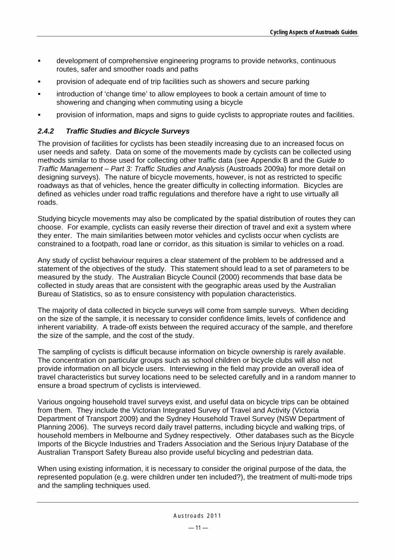
2.4.2 Traffic Studies and Bicycle Surveys
The provision of facilities for cyclists has been steadily increasing due to an increased focus on user needs and safety. Data on some of the movements made by cyclists can be collected using methods similar to those used for collecting other traffic data (see Appendix B and the Guide to Traffic Management – Part 3: Traffic Studies and Analysis (Austroads 2009a) for more detail on designing surveys). The nature of bicycle movements, however, is not as restricted to specific roadways as that of vehicles, hence the greater difficulty in collecting information. Bicycles are defined as vehicles under road traffic regulations and therefore have a right to use virtually all roads.
Studying bicycle movements may also be complicated by the spatial distribution of routes they can choose. For example, cyclists can easily reverse their direction of travel and exit a system where they enter. The main similarities between motor vehicles and cyclists occur when cyclists are constrained to a footpath, road lane or corridor, as this situation is similar to vehicles on a road.
Any study of cyclist behaviour requires a clear statement of the problem to be addressed and a statement of the objectives of the study. This statement should lead to a set of parameters to be measured by the study. The Australian Bicycle Council (2000) recommends that base data be collected in study areas that are consistent with the geographic areas used by the Australian Bureau of Statistics, so as to ensure consistency with population characteristics.
The majority of data collected in bicycle surveys will come from sample surveys. When deciding on the size of the sample, it is necessary to consider confidence limits, levels of confidence and inherent variability. A trade-off exists between the required accuracy of the sample, and therefore the size of the sample, and the cost of the study.
The sampling of cyclists is difficult because information on bicycle ownership is rarely available. The concentration on particular groups such as school children or bicycle clubs will also not provide information on all bicycle users. Interviewing in the field may provide an overall idea of travel characteristics but survey locations need to be selected carefully and in a random manner to ensure a broad spectrum of cyclists is interviewed.
Various ongoing household travel surveys exist, and useful data on bicycle trips can be obtained from them. They include the Victorian Integrated Survey of Travel and Activity (Victoria Department of Transport 2009) and the Sydney Household Travel Survey (NSW Department of Planning 2006). The surveys record daily travel patterns, including bicycle and walking trips, of household members in Melbourne and Sydney respectively. Other databases such as the Bicycle Imports of the Bicycle Industries and Traders Association and the Serious Injury Database of the Australian Transport Safety Bureau also provide useful bicycling and pedestrian data.
When using existing information, it is necessary to consider the original purpose of the data, the represented population (e.g. were children under ten included?), the treatment of multi-mode trips and the sampling techniques used.
Cycling Aspects of Austroads Guides
A u s t r o a d s 2 0 1 1
— 12 —
2.5 Type of Bicycle Facility Required When considering the type of bicycle facility, such as bicycle lanes or shared use paths, the two guiding principles are separating cyclists from motor vehicles and providing a high level of priority for cyclists across driveways and through intersections (Section 4.6.5, Austroads 2009b).
Figure 2.1 provides an example of guidelines for the selection of an appropriate type of bicycle facility. It relates the degree of separation required for cyclists to the speed and volume of general traffic. It should, however, be noted that jurisdictional policy and implementation strategies may also influence selection of particular facilities.
A key message of Figure 2.1 is that the separation of cyclists from motor vehicles is not always required on local and collector roads that have traffic volumes less than 5000 vehicles per day and speeds less than 40 km/h. In these circumstances, it is considered appropriate that adult cyclists may share the road with motor vehicles and younger cyclists may use the footpath where this is supported by appropriate road rules.
However, where space permits, it is still important to consider the provision of a separated bicycle facility such as a bicycle lane or a shared use path.
Road authorities should aim to comply with this guidance, particularly in greenfields situations, but the outcome may not always be optimal in retro-fit situations. In addition, note that experienced road cyclists are unlikely to use off-road facilities with low design speeds, even on routes where the road carries high volume, high speed traffic. On-road bicycle lanes or suitable road shoulders may still be required in addition to off-road facilities.

Cycling Aspects of Austroads Guides
A u s t r o a d s 2 0 1 1
— 13 —
Source: Figure 4.7 of Austroads (2009b). RTA (2005, Fig 3.2).
Figure 2.1: Separation of cyclists and motor vehicles by speed and volume
More detailed guidance on the selection of particular types of on-road and off-road bicycle facilities can be found in Table 3.2 of the Guide to Traffic Management – Part 5: Road Management (Austroads 2008a).
2.6 Combining Bicycle Travel with Public Transport The combination of multi-mode travel where people cycle to interchanges and transfer to public transport can substantially increase the range of bicycle travel. Public transport authorities should make provision for carriage or storage of bicycles in conjunction with the inclusion of transport hubs as specific destinations within the bicycle route network (Section 4.6.8, Austroads 2009b).
Examples of such provision can include easy-to-use on-board storage facilities, easy access to stations with secure long-term weatherproof parking or parking rails for short-term parking.

Cycling Aspects of Austroads Guides
A u s t r o a d s 2 0 1 1
— 14 —
2.7 Integrated Land Use/Bicycle Planning The bicycle network needs to be separated from, yet integrated with the main road, pedestrian and public transport systems. This will necessitate regular crossings in order to sustain the coverage and continuity of the network for cyclists. The actual measures which can be adopted to facilitate movement will be influenced by functional road hierarchy considerations such as the access and movement functions of the road.
Note, however, that facilities will also often be shared between cyclists and other traffic such as motorised traffic.
2.8 Local Area Traffic Management Guidance for cycling facilities in local areas is provided in the Guide to Traffic Management – Part 8: Local Area Traffic Management (Austroads 2008b).
Bicycle lanes (Figure 2.2) are not often needed in local areas where the speed environment is low and the mixture of bicycle and vehicle traffic works well together.
Advisory treatments are provided to indicate or advise road users of the potential presence of cyclists and of the location where cyclists may be expected to ride on the street. They consist of pavement markings and warning and guide signs, and as such have no regulatory function. As with bicycle/car parking lanes, collisions between cyclists and opening doors of parked cars are a significant concern to cyclists.
Bicycle bypasses provide a safe and comfortable mechanism for cyclists to avoid passing through devices. They are desirable where there is a need to separate cyclists from other traffic to make routes more attractive for travel or to avoid squeeze points, adverse surface conditions, and other obstacles. The design of bicycle bypasses should be done in such as way that they take the cyclist past the device to a separated space or they allow safe reintegration with motorised traffic.
Source: Figure 7.32 of Austroads (2008b).
Figure 2.2: Bicycle lane example

Cycling Aspects of Austroads Guides
A u s t r o a d s 2 0 1 1
— 15 —
Other bicycle facilities that may be appropriate in local areas include contra-flow bicycle lanes, wide kerbside lanes, bus/bicycle lanes and supplementary street treatments. Table 2.4 describes the use, advantages and disadvantages of bicycle lanes, advisory treatments and bypasses in LATM treatments whilst Figure 2.3 shows examples of treatments. Further information on the provision and design of bicycle lanes, advisory treatments, bypasses and other facilities is provided in Section 4.
Table 2.4: Use, advantages and disadvantages of bicycle lanes, advisory treatments and bypasses in LATM schemes
Use Advantages Disadvantages
It is appropriate to use bicycle lanes, advisory treatments, and bypasses: where there is a significant difference in
the speed of vehicular and bicycle traffic (i.e. > 20 km/h)
where it is desirable to separate cyclists from other traffic (e.g. for reasons of safety)
anywhere cycling needs to be encouraged (e.g. along major routes near town or city centres).
It is inappropriate to use bicycle lanes, treatments and bypasses where they will restrict the movement of buses.
The advantages of bicycle lanes, advisory treatments and bypasses include: increase in cyclist safety improvement in accessibility and
connectivity of the bicycle network they can be used to narrow the width of
traffic lanes they promote the use of alternative modes
of transport.
The disadvantages of bicycle lanes, advisory treatments and bypasses include: separate facilities may be expensive facilities may be incompatible with other
LATM devices.
City of Gold Coast, Queensland City of Unley, South Australia
Source: Figure 7.33 of Austroads (2008b).
Figure 2.3: Examples of bicycle bypasses of LATM devices

Cycling Aspects of Austroads Guides
A u s t r o a d s 2 0 1 1
— 16 —
2.9 Traffic Management in Activity Centres 2.9.1 Planning Context for Cycling in Activity Centres
Austroads Guide to Traffic Management – Part 7: Traffic Impacts in Activity Centres (Austroads 2009c) considers the requirements of cyclists in the overall planning of activity centres and practitioners should refer to the Guide for further information.
The key planning principle for bicycle travel in relation to activity centres is typically to maximise cyclists’ accessibility to centres, services, facilities and employment locations.
Bicycle access to destinations within the centre will comprise the terminal part of a journey. The scale and the nature of the roads and streets through an activity centre will determine the extent to which defined bicycle routes will be required within it. While approach routes to key foci such as a railway station will need to be defined and enhanced, it may not be necessary to provide for designated bicycle access to every possible destination. Deciding on where bicycles can be parked, and how bicycles get to those points, is part of the traffic management task.
Planning for bicycle travel and access is a high priority in all jurisdictions. As a component of sustainable transport policies, bicycle use must be actively encouraged in the planning, design and management of a centre. There are many government policies and guidelines on this subject, and these local sources should be consulted. Typical guiding principles and criteria for bicycle planning are shown in Table 2.5 . Where appropriate, these will also influence the management of bicycle movement within centres.

Cycling Aspects of Austroads Guides
A u s t r o a d s 2 0 1 1
— 17 —
Table 2.5: Example of guiding principles and criteria for bicycle plans
Principle Criteria
Coherence Continuity of routes
Consistent quality of routes and facilities
Easy to follow
Freedom of choice of routes
Directness Efficient operating speed
Delay time
Detour factor*
Safety Minimum risk of accidents on routes
Minimum risk of conflict with car traffic
Minimum risk of unsafe infrastructure
Attractiveness Support for the system
Attractiveness of environment
Perception of social safety
System attractiveness
Comfort Smoothness of ride
Comfortable gradient
Minimum obstruction from vehicles
Reduced need to stop (number of stops per km)
Protection from adverse climate
End of trip facilities Provision of secure bicycle parking in convenient locations
Provision of change facilities for commuters/workers
*Detour factor is the actual route length on the road/bicycle network divided by the distance measured in a straight line between the trip origin and the trip destination.
Source: Table 2.4 of Austroads (2009c). Based on RTA NSW (2005).
Inevitably, there will be a degree of compromise within many activity centres, for instance in terms of stops and delays. Traffic management also needs to allow for the reality that bicycles are not compatible with pedestrian spaces, especially where pedestrian movement is moderate to intense, and to that extent the two modes must be considered separately in detailed design and management of the centre. In addition, it is not generally expected that bicycle movement from one part of the centre to another must always be accommodated in planning and management.
Matters concerning planning for bicyclists in centres that may impact on traffic management include the following:
provision for direct and convenient bicycle access into the centre from surrounding areas, and thus the way in which the centre’s internal networks integrate with routes used by cyclists to access the centre
provision for bicycle movement through the centre and to bicycle parking/storage locations, which will affect road cross-section design, and the location of bicycle parking facilities and how access to them is provided
bicycle parking arrangements, especially at places of employment and at rail stations.
Cycling Aspects of Austroads Guides
A u s t r o a d s 2 0 1 1
— 18 —
2.9.2 Bicycles in Activity Centres
In order to satisfy policy intentions that positive steps are to be taken to encourage bicycling, and to provide the necessary physical conditions, traffic management can play a supportive role to the planning and urban design measures that are taken (Section 3.8.3, Austroads 2009c). The key objectives, from a traffic management point of view, are to:
maximise cycling accessibility to centres and the services, facilities and employment they contain
design streets that comfortably and safely accommodate cyclists
ensure that vehicle traffic does not compromise a good cycling environment
ensure that cycling does not compromise a good walking environment.
A number of issues related to bicycles in activity centres arise from these objectives, which traffic management can influence or determine:
bicycle planning as it relates to activity centres
bicycle access within the centre
bicycle facilities
interaction with pedestrians
interaction with other traffic
bicycle parking.
2.10 Traffic Impacts of Developments Depending on the nature and scale of a development, cyclists will access it via the adjacent road system from more distant locations, from nearby residential areas or from nearby bicycle routes. Where there are nearby bicycle facilities (off-road bicycle paths or on-road bicycle lanes) bicycle links into the development need to be considered. Convenient, safe and attractive cycle access should be provided.
The Guide to Traffic Management – Part 12: Traffic Impacts of Developments (Austroads 2009f) is designed to help traffic and transport practitioners identify and manage the impacts on the road system arising from land use developments, and contains information on the consideration of cyclist needs in assessing access requirements to and within developments.
Secure bicycle parking is an essential part of a network of bicycle facilities. Bicycle parking needs to be provided in a location that is convenient, and visible to the public for security reasons. In some planning schemes there are specific requirements for bicycle parking at developments in particular land use zones. Australian Standard AS 2890.3: 1993 outlines the requirements for bicycle parking.

Cycling Aspects of Austroads Guides
A u s t r o a d s 2 0 1 1
— 19 —
3 BICYCLE RIDER REQUIREMENTS
3.1 General The basic bicycle rider requirements that are generally considered necessary for convenient, efficient and safe travel by bicycle are presented in this section. Additional information on rider requirements is provided in the Guide to Road Design – Part 3: Geometric Design (Commentary 9, Austroads 2010g) and in the Guide to Road Design – Part 6A: Pedestrian and Cyclist Paths (Section 4, Austroads 2009m).
A very important requirement of many cyclists, in addition to those described below, is separation from motor vehicles because it enhances their safety and comfort, provided that the treatment results in a satisfactory level of service and does not result in a loss of priority at intersections and driveways. Commuter cyclists, for example, are unlikely to use a separated facility that results in a significantly greater travel time than alternative on-road routes.
In relation to path and road engineering all cyclists have six basic requirements whenever they ride, namely:
space to ride
a smooth surface
speed maintenance
sight lines
connectivity
information.
These requirements apply equally on roads and on paths.
By implication the important objective of a safe environment for cyclists must exist, given the provision of space to ride, a smooth surface, adequate sight lines and the ability of cyclists to maintain their speed.
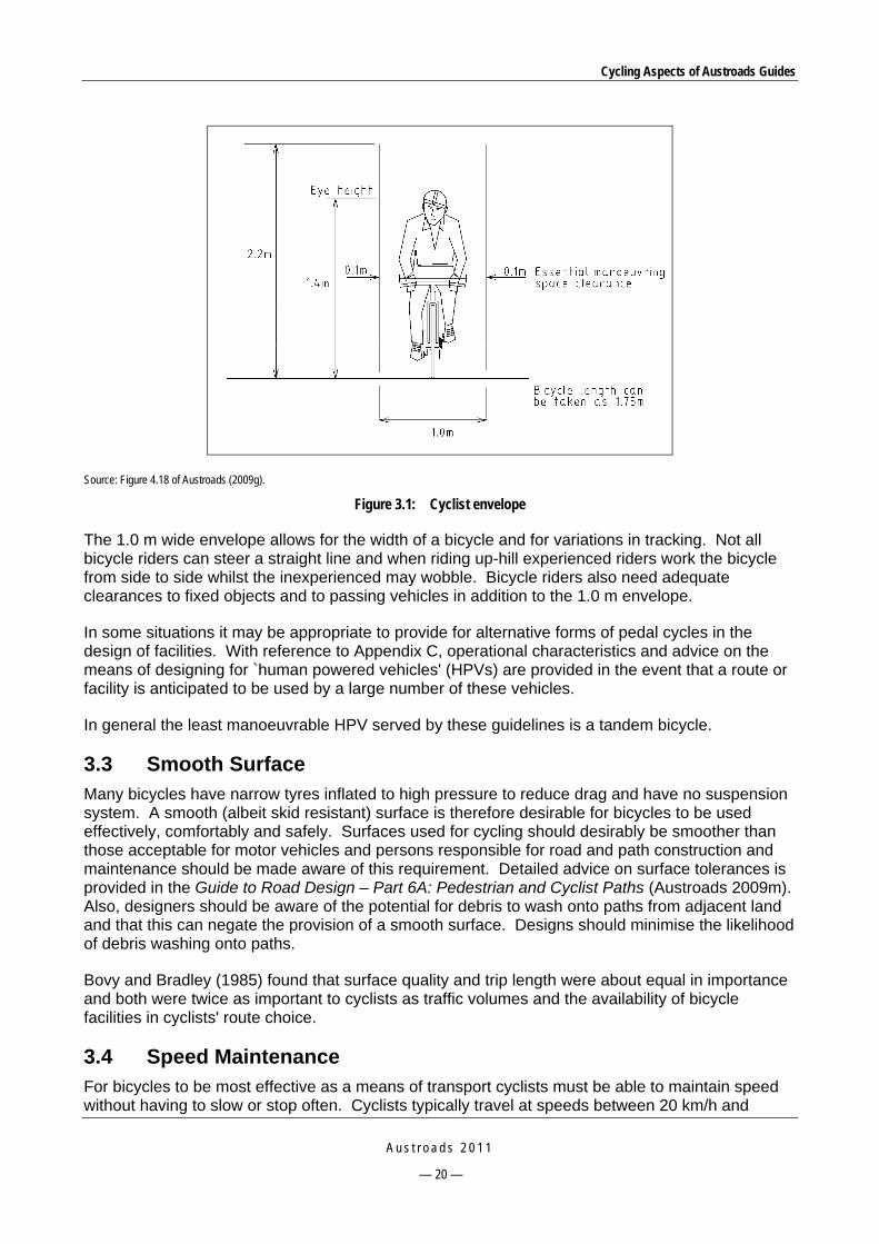
3.2 Space to Ride The bicycle design envelope and clearances shown in Figure 3.1 provide the basis for the design of the bicycle facilities described in later sections of this document. It is important for designers to understand the basis of the design including clearance requirements so that they can make judgements in difficult situations where knowledge of minimum space requirements is needed. The envelope is relevant to the design of lanes on roads, off-road paths and bicycle parking facilities.
Cycling Aspects of Austroads Guides
A u s t r o a d s 2 0 1 1
— 20 —
Source: Figure 4.18 of Austroads (2009g).
Figure 3.1: Cyclist envelope
The 1.0 m wide envelope allows for the width of a bicycle and for variations in tracking. Not all bicycle riders can steer a straight line and when riding up-hill experienced riders work the bicycle from side to side whilst the inexperienced may wobble. Bicycle riders also need adequate clearances to fixed objects and to passing vehicles in addition to the 1.0 m envelope.
In some situations it may be appropriate to provide for alternative forms of pedal cycles in the design of facilities. With reference to Appendix C, operational characteristics and advice on the means of designing for `human powered vehicles' (HPVs) are provided in the event that a route or facility is anticipated to be used by a large number of these vehicles.
In general the least manoeuvrable HPV served by these guidelines is a tandem bicycle.
3.3 Smooth Surface Many bicycles have narrow tyres inflated to high pressure to reduce drag and have no suspension system. A smooth (albeit skid resistant) surface is therefore desirable for bicycles to be used effectively, comfortably and safely. Surfaces used for cycling should desirably be smoother than those acceptable for motor vehicles and persons responsible for road and path construction and maintenance should be made aware of this requirement. Detailed advice on surface tolerances is provided in the Guide to Road Design – Part 6A: Pedestrian and Cyclist Paths (Austroads 2009m). Also, designers should be aware of the potential for debris to wash onto paths from adjacent land and that this can negate the provision of a smooth surface. Designs should minimise the likelihood of debris washing onto paths.
Bovy and Bradley (1985) found that surface quality and trip length were about equal in importance and both were twice as important to cyclists as traffic volumes and the availability of bicycle facilities in cyclists' route choice.
3.4 Speed Maintenance For bicycles to be most effective as a means of transport cyclists must be able to maintain speed without having to slow or stop often. Cyclists typically travel at speeds between 20 km/h and

Cycling Aspects of Austroads Guides
A u s t r o a d s 2 0 1 1
— 21 —
30 km/h although they may reach in excess of 50 km/h down hills. Once slowed or stopped it takes considerable time and effort to regain the desired operating speed.
Bicycle routes, especially off-road, should be designed for continuous riding, minimising the need to slow or stop for any reason including steep gradients, rough surfaces, sharp corners, obscured sight lines, intersections, or to give way to other people because the width available is too narrow. On many roads cyclists are confined to the extreme left-hand side by motor vehicles and a rough surface prevents cyclists from maintaining an acceptable speed.
3.5 Sight Lines It is important that appropriate sight lines are provided between a cyclist’s eye height and pedestrians to assist in minimising conflict, and between a cyclist’s eye height and the path surface so that cyclists can stop in the event that a hazard exists on the path (e.g. mud deposited during inundation, potholes due to washouts, broken glass, and fallen tree limbs).
Designers should ensure that roads are designed to meet the sight distance requirements of Section 5 of Austroads (2010g) and Section 3 of the Guide to road design – Part 4A: Unsignalised and signalised intersections (Austroads 2010i). Paths should be designed to meet the sight distance requirements of Austroads (2009m).
Designers should therefore resist the temptation to provide curves that are smaller than necessary (e.g. to create an artificially winding path for aesthetics or urban design reasons). It is much better for the safety of path users if larger curves with greater sight distance are provided.
3.6 Connectivity Connectivity is that quality of a bicycle route or route network, describing the continuous nature of facilities or of the continuous nature of desired conditions. Practitioners should refer to Commentary C9, Section C9.5 of Austroads (2010g) and Section 4.2.1 of Austroads (2009m) for further information on connectivity.
Cyclists need to be able to undertake and complete meaningful trips by bicycle. For recreation it may be from a residential area to a picnic spot, or for a specific purpose trip from home to work or the shops. Bicycle routes comprising roads and paths should combine to form an effective, convenient and safe network.
Connectivity is an important aspect of the construction of effective bicycle routes. Before a route is constructed the purpose of the route should be identified as well as the routes which cyclists are likely to use in travelling to and from the paths, bicycle lanes and roads forming the network.
A route for cyclists which starts and ends abruptly is undesirable and may be hazardous as it may lure inexperienced cyclists to a point where they are at risk, perhaps having to ride along or across busy roads to complete their intended trip.
On-road bicycle facilities may take the form of:
dedicated unprotected bicycle lanes including full-time or part-time operation with or without adjacent parking
contra-flow bicycle lanes
protected bicycle lanes using kerbs and medians to physically separate motor vehicles and cyclists
wide sealed road shoulders

Cycling Aspects of Austroads Guides
A u s t r o a d s 2 0 1 1
— 22 —
advisory treatments
4.5 m wide kerb-side motor vehicle traffic lanes.
Off-road bicycle facilities may take the form of:
exclusive bicycle paths
separated paths – bicycle and pedestrian
shared use paths.
3.7 Information Bicycle routes should be signposted to indicate both destinations and the distances to them.
Maps should be available showing the route, facilities and points of interest along it, its relationship to the surrounding road system, and its relationship to relevant community facilities. The map and the signposting should be consistent in terms of destination names and other information.

Cycling Aspects of Austroads Guides
A u s t r o a d s 2 0 1 1
— 23 —
4 BICYCLE FACILITIES ON ROAD (MID-BLOCK)
4.1 General The ultimate aim in the management of a road network or individual road length is to achieve a balance in the competing needs of road user groups. It is desirable (although not always possible) that a road design should provide adequate operating space and appropriate treatments for all road users so that they can move safely and efficiently throughout the network. The Guide to Road Design – Part 3: Geometric Design (Austroads 2010g) provides guidance on the facilities that may be provided for cyclists within a road cross-section.
In local streets it is usually not necessary to make special provision for cyclists as the lower speed of motor traffic should enable cyclists to safely share the road with other users. On arterial roads and collector roads it is usually necessary to ensure that adequate space exists for cyclists to share the road safely and comfortably, particularly when the road forms part of a principal or regional bicycle network. It may be possible to reduce the widths of other lanes in order to allocate additional space to the left hand lane for joint use by cyclists.
Depending on the nature of the road, abutting land use, the function of the road in bicycle networks, and the number and types of cyclists using the road, the following types of on-road facilities may be considered for inclusion in a road cross-section. Moreover, the provision of cyclist facilities should be based on the hierarchy of needs, delivered in order of level of safety and priority (Austroads 2010g):
1. Off-road exclusive bicycle path (within the road corridor)
2. On-road segregated bicycle lanes – median or similar separation
3. On-road exclusive bicycle lane
4. On-road peak period exclusive bicycle lane
5. On-road bicycle/car parking lane
6. Wide kerbside lane
7. Narrow kerbside lane.
The facilities described in this section are those applied within the carriageway of new roads or within the established road carriageway in the case of existing roads.
Off-road bicycle facilities typically take the form of shared pathways for use by both cyclists and pedestrians, and these are described in more detail in Section 7, and the Guide to Road Design – Part 6A: Pedestrian and Cyclist Paths (Austroads 2009m).
Factors to be considered with respect to horizontal and vertical alignment, gradients, cross-section and clearances are provided in Sections 4.8.2 to 4.8.4 in Austroads 2010g. Road alignments and gradients are almost always determined by motor vehicle requirements. Widths and clearances are therefore the important elements that relate to on-road facilities.
In most instances, a range of treatment widths have been provided in the sections below. Whilst tables are provided to guide the choice of width, when choosing the actual lane or treatment widths for particular sites practitioners should carefully assess:
parking conditions
motor vehicle speed

Cycling Aspects of Austroads Guides
A u s t r o a d s 2 0 1 1
— 24 —
motor vehicle volume
bicycle/parking lane width
bicycle volume
car lane width
percentage of heavy vehicles
alignment of road.
The demand for the adjoining motor traffic lanes is also an important issue in assessing the adequacy of bicycle lanes. Where a road is operating close to capacity and narrow bicycle lanes exist, there may be insufficient opportunities or it may be hazardous for cyclists to pass each other. Therefore, if a demand for passing within bicycle lanes is likely in peak hours a minimum bicycle lane width of 2.0 m should be provided along congested roads. Surface conditions and edge clearances to kerbs need to be considered in the assessment of the capacity of road lanes for bicycles.
4.2 Provision for Cyclists on Roads 4.2.1 General
Under the Australian Road Rules cyclists may move along roads in three areas defined in the rules as a bicycle lane, a marked lane or a shoulder. An example of a guide to the use of these facilities is provided in Figure 2.1. Cyclists may also ride in special-purpose lanes if permitted by the relevant jurisdiction, and are required to obey the relevant rules when using a bicycle lane, marked lane or shoulder.
4.2.2 Exclusive Bicycle Lanes
Exclusive bicycle lanes for cyclists (Section 4.8.7 of Austroads 2010g) should be viewed as part of a bicycle network providing the connectivity required to enable convenient and safe trips by bicycle. An exclusive bicycle lane is:
a lane created by ‘bicycle only’ signs and delineated by pavement markings (Figure 4.1)
the preferred treatment for cyclists on roads without any form of physical separation
generally located at the left side of a road.
Exclusive bicycle lanes should be provided on both sides of the road where possible so that use is in the same direction as motor vehicle traffic.

Cycling Aspects of Austroads Guides
A u s t r o a d s 2 0 1 1
— 25 —
Note: Green coloured surface treatments should only be used to increase driver and cyclist awareness of an exclusive bicycle lane, and to discourage drivers from encroaching into an exclusive bicycle lane. The treatment should be used sparingly to maintain its effectiveness.
Source: Figure 4.24 of Austroads (2009g).
Figure 4.1: An example of an exclusive bicycle lane
Motor traffic is generally prohibited by traffic regulations from travelling in the bicycle lane except to access property or to turn at intersections. Similarly, parking in the lane may be prohibited either full-time or otherwise during the designated periods of operation of the lane (refer to local road rules).
Exclusive bicycle lanes:
may combine with particular characteristics of the road to form different types of treatment (e.g. in conjunction with parallel or angle parking); refer to Section 4.3
may sometimes be installed as part-time facilities by the removal of car parking along arterial roads during certain times (e.g. peak periods); however, an adequate level of parking enforcement is required for the treatment to be safe and effective for cyclists
can be often very difficult or impracticable to achieve for existing road conditions. However, there are a range of other forms of lanes and treatments that may be provided to improve the quality of a cyclist’s riding experience on the road
may be appropriate or highly desirable (depending on site conditions) where
— bicycle traffic is concentrated (e.g. near schools or along major routes near city or town centres)
— an existing or future significant demand for bicycle travel can be demonstrated (e.g. where traffic volumes and speeds deter cyclists from using an otherwise favourable route)
— they are needed to provide continuity within a bicycle route network
— a road is carrying or is likely to carry more than 3000 vehicles per day and/or a significant percentage of heavy vehicles.
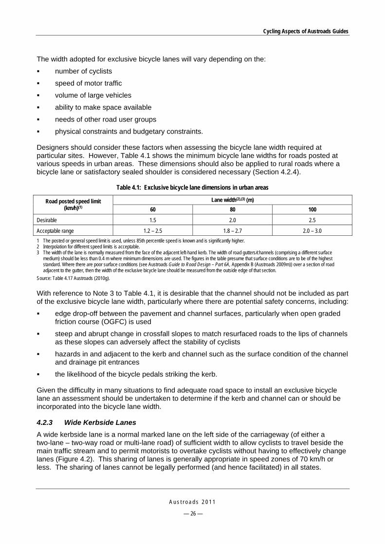
Cycling Aspects of Austroads Guides
A u s t r o a d s 2 0 1 1
— 26 —
The width adopted for exclusive bicycle lanes will vary depending on the:
number of cyclists
speed of motor traffic
volume of large vehicles
ability to make space available
needs of other road user groups
physical constraints and budgetary constraints.
Designers should consider these factors when assessing the bicycle lane width required at particular sites. However, Table 4.1 shows the minimum bicycle lane widths for roads posted at various speeds in urban areas. These dimensions should also be applied to rural roads where a bicycle lane or satisfactory sealed shoulder is considered necessary (Section 4.2.4).
Table 4.1: Exclusive bicycle lane dimensions in urban areas
Road posted speed limit (km/h)(1)
Lane width(2),(3) (m)
60 80 100
Desirable 1.5 2.0 2.5
Acceptable range 1.2 – 2.5 1.8 – 2.7 2.0 – 3.0
1 The posted or general speed limit is used, unless 85th percentile speed is known and is significantly higher. 2 Interpolation for different speed limits is acceptable. 3 The width of the lane is normally measured from the face of the adjacent left-hand kerb. The width of road gutters/channels (comprising a different surface
medium) should be less than 0.4 m where minimum dimensions are used. The figures in the table presume that surface conditions are to be of the highest standard. Where there are poor surface conditions (see Austroads Guide to Road Design – Part 6A, Appendix B (Austroads 2009m)) over a section of road adjacent to the gutter, then the width of the exclusive bicycle lane should be measured from the outside edge of that section.
Source: Table 4.17 Austroads (2010g).
With reference to Note 3 to Table 4.1, it is desirable that the channel should not be included as part of the exclusive bicycle lane width, particularly where there are potential safety concerns, including:
edge drop-off between the pavement and channel surfaces, particularly when open graded friction course (OGFC) is used
steep and abrupt change in crossfall slopes to match resurfaced roads to the lips of channels as these slopes can adversely affect the stability of cyclists
hazards in and adjacent to the kerb and channel such as the surface condition of the channel and drainage pit entrances
the likelihood of the bicycle pedals striking the kerb.
Given the difficulty in many situations to find adequate road space to install an exclusive bicycle lane an assessment should be undertaken to determine if the kerb and channel can or should be incorporated into the bicycle lane width.
4.2.3 Wide Kerbside Lanes
A wide kerbside lane is a normal marked lane on the left side of the carriageway (of either a two-lane – two-way road or multi-lane road) of sufficient width to allow cyclists to travel beside the main traffic stream and to permit motorists to overtake cyclists without having to effectively change lanes (Figure 4.2). This sharing of lanes is generally appropriate in speed zones of 70 km/h or less. The sharing of lanes cannot be legally performed (and hence facilitated) in all states.

Cycling Aspects of Austroads Guides
A u s t r o a d s 2 0 1 1
— 27 —
Wide kerbside lanes are appropriate on all major traffic routes and collector roads, whether divided or undivided, on sections of road where parking is either minimal or prohibited during peak periods.
Source: Figure 4.29 of Austroads (2009g).
Figure 4.2: Wide kerbside lane
A guide to the width of wide kerbside lanes is provided in Table 4.2.
Table 4.2: Wide kerbside lane dimensions
Road posted speed limit(1) (km/h)
Lane width(2),(3) (m)
60 km/h 80 km/h
Desirable minimum 4.2 4.5
Acceptable range 3.7 – 4.5 4.3 – 5.0
1 The posted or general speed limit is used, unless 85th percentile speed is known and is significantly higher. 2 Interpolation for different speed limits is acceptable. 3 The width of the lane is normally measured from the face of the adjacent left-hand kerb. The width of road gutters/channels (comprising a different surface
medium) should be less than 0.4 m where minimum dimensions are used. The figures in the table presume that surface conditions are to be of the highest standard. Where there are poor surface conditions over a section of road adjacent to the gutter, then the width of the wide kerbside lane should be measured from the outside edge of that section.
Source: Table 4.20 of Austroads (2010g).
Table 4.2 indicates the desirable width and acceptable range of width for wide kerbside lanes in 60 km/h and 80 km/h speed zones (unless noted otherwise). Whilst the table suggests that a 4.5 m lane width is desirable in 80 km/h zones designers should understand that it is always preferable to provide a marked exclusive bicycle lane instead of a wide kerbside lane, particularly in higher speed zones (i.e. 70 km/h and 80 km/h). Where space cannot be made available for an exclusive bicycle lane a wide kerbside lane can offer benefit to cyclists in terms of safety and comfort.
Other considerations when using wide kerbside lanes are:
Where kerbside parking is significant in the off-peak period, the wide kerbside lane should be at least 4.0 m wide so that the lane will function satisfactorily as a bicycle/parking lane during these periods even though special pavement marking is not provided for guidance.
Exclusive bicycle lanes are preferred where a road has regular curves or where an unusually high number of heavy vehicles use the road.
For roads with a posted speed limit of 80 km/h, wide kerbside lanes are only suitable where the demand for parking is low.
Cycling Aspects of Austroads Guides
A u s t r o a d s 2 0 1 1
— 28 —
4.2.4 Sealed Shoulders
Where a road is unkerbed and provision for cyclists is required, a smooth sealed shoulder is the preferred treatment. Although warrants do not exist specifically for the provision of sealed shoulders for cyclists there are many instances on rural roads where the sealing of shoulders is justified specifically to make roads safer for cycling.
Austroads (2010g) suggests that Table 4.5 of that Guide provides some guidance as to the appropriate standard to be provided for cyclists. This table relates shoulder width to traffic volume and cyclists’ requirements are referred to only in note 2 to the table, which states:
Where significant numbers of cyclists use the roadway, consideration should be given to fully sealing the shoulders. Suggest use of a maximum size 10 mm seal within a 20 km radius of towns.
Widths required for sealed shoulders for bicycle usage are generally the same as those required for exclusive bicycle lanes, as shown in Table 4.1. Although this table relates the width to speed, the widths are not inconsistent with Table 4.5 in Austroads (2010g). Provision for cyclists should be maintained through intersections, past driveways, and at those locations where the road is kerbed along lengths of road otherwise treated with sealed shoulders. Where a chip seal is used to seal the shoulders, consideration should be given to the use of a maximum size 10 mm stone to provide a smoother and less abrasive riding surface, as a larger size stone can cause concern for cyclists.
4.2.5 Bus/Bicycle Lanes
Whilst it is desirable that bicycles are accommodated in a separate bicycle lane, examples exist where bicycles have successfully shared in the use of bus lanes. In most circumstances cyclists may be permitted to use bus lanes when they are located next to the kerb on arterial or local roads. Considerations for provision of bicycles within bus lanes should be based on:
the number of cyclists
frequency of bus services
the number of bus stops
time required to set down and pick up passengers.
Generally, buses will overtake cyclists between bus stops and cyclists will catch up and overtake buses at bus stops. This process can lead to ‘leap-frogging’ along the bus lane.
The key to managing the impact of this process on the level of service to buses and cyclists is to provide a bus lane that is wide enough to accommodate these movements. A guide to the width is provided in Table 4.3. Alternatively, it may be possible to provide a separate on-road bicycle lane or off-road bicycle path adjacent to the bus lane and at bus stops.

Cycling Aspects of Austroads Guides
A u s t r o a d s 2 0 1 1
— 29 —
Table 4.3: Width of kerbside bus lanes
Width of bus lane (m)
Speed zone (km/h) 60 70 80 Comment
Minimum width of bus lane that can be shared with cyclists 3.7 4.0 4.3
Bus lanes of this width are considered wide kerbside lanes and allow cyclists and buses to share the bus lane.
Bus lanes of this width may be acceptable for routes that carry between 50 and 100 cyclists or where bus headways are between 15 and 30 minutes in the peak hour.
Minimum width of separated on-road bicycle lane 1.2 1.5 1.8
It is considered desirable to provide separated on-road bicycle lanes adjacent to bus lanes on routes that carry more than 100 cyclists and where bus headways are 15 minutes or less in the peak hour.
Minimum width of bus lane and separated on-road bicycle lane
4.2 4.6 5.1 This is the minimum width of the bus lane plus the minimum width of a separated on-road bicycle lane to provide the minimum separation between cyclists and buses.
Source: Table 4.22 of Austroads (2010g).
4.2.6 Advisory Treatments
Advisory treatments are used to indicate or advise road users of the potential presence of cyclists and of the location where cyclists may be expected to ride on a road. They use pavement markings, warning signs or guide signs, and as such have no regulatory function. The purpose of these treatments is usually to define a bicycle route rather than a type of facility to which specific road rules apply. The form of the treatment is a matter for local jurisdictions.
4.3 Types of Bicycle Lane Treatments This section briefly describes the various types of bicycle lane treatments and provides guidance on use and the width of the treatments.
4.3.1 Bicycle/Car Parking Lanes
Bicycle/car parking lanes are most appropriate where the street is wide, there is a demand for parking (and where road space and capacity requirements allow parking throughout the day). It is most important to provide a width that is adequate to accommodate parked vehicles, operating space for cyclists and adequate clearance to accommodate the opened door of parked vehicles.
Further discussion is provided in Section 4.8.10 of Austroads 2010g. Bicycle/car parking lanes may be provided in conjunction with parallel parking or angle parking.
With parallel parking
Table 4.4 provides guidance on widths of bicycle/car parking lanes with parallel parking and the associated layout is shown Figure 4.3. Also, it should be noted that:
4.5 m is the acceptable maximum width as a greater width may result in moving cars attempting to utilise the bicycle lane. It provides acceptable clearances in cases where parking turnover is significant or traffic speeds are in excess of 60 km/h but no greater than 80 km/h
4.2 m is the desirable width where speeds are about 60 km/h as it provides comfortable clearance to parked cars

Cycling Aspects of Austroads Guides
A u s t r o a d s 2 0 1 1
— 30 —
4.0 m is the acceptable minimum width where traffic speeds are about 60 km/h as it enables a cyclist to travel adjacent to parked and moving cars at a reasonable speed with minimum clearances.
Table 4.4: Bicycle/car parking lane dimensions (parallel parking)
Road posted speed limit (km/h)
Overall facility width (m)
60 km/h 80 km/h
Desirable minimum 4.0 4.5
Acceptable range 3.7 – 4.5 4.0 – 4.7
Source: Table 4.18 Austroads (2010g).
Source: Figure 4.27 of Austroads (2009g).
Figure 4.3: Typical bicycle/car parking lanes layout (parallel parking)
With angle parking
This treatment is illustrated in Figure 4.4. The entry and exit conditions of angle parking require that a high level of protection is provided to cyclists. The provision of marked bicycle lanes adjacent to angle parking is therefore most desirable. Whilst an opening car door does not pose a threat to cyclists in the case of angle parking, cyclists have to be alert to vehicles reversing (regardless of orientation) into their path. It is most important in cases where parallel parking is being converted to angle parking that the needs of cyclists are given adequate consideration.
This treatment is appropriate only where the posted or general speed limit is less than or equal to 70 km/h. The provision of kerbed projections or other treatments including channelisation is recognised as extremely important. Treatments should be constructed immediately to the left of the bicycle lanes at the start of this type of lane facility and at regular intervals to limit the incidence of vehicles travelling over, or to the left of, the bicycle lane.

Cycling Aspects of Austroads Guides
A u s t r o a d s 2 0 1 1
— 31 —
Source: Figure 4.28 of Austroads (2009g).
Figure 4.4: Typical bicycle/car parking lanes layout (angle parking)
Table 4.5 is a guide to the overall width required to provide a bicycle/car parking lane with angle parking.
Table 4.5: Bicycle/car parking lane dimensions (angle parking)
Parking angle (degrees) Overall facility width (m)
45 60 70
Desirable 7.3 7.6 8.0
Acceptable range 7.1 – 7.8 7.4 – 8.1 7.8 – 8.5
Notes:
Measured from kerb face to the marked line defining the left edge of the traffic lane. These dimensions assume parked cars can overhang the kerb. An additional 0.6 m should be added where overhanging of the kerb is not possible (i.e. parking to a wall).
This facility should be constructed only where the speed limit is 70 km/h or less. The value of 90 km/h in the right-hand column of Table 4.19 in Austroads (2009g) is erroneous.
Source: Table 4.19 of Austroads (2010g).
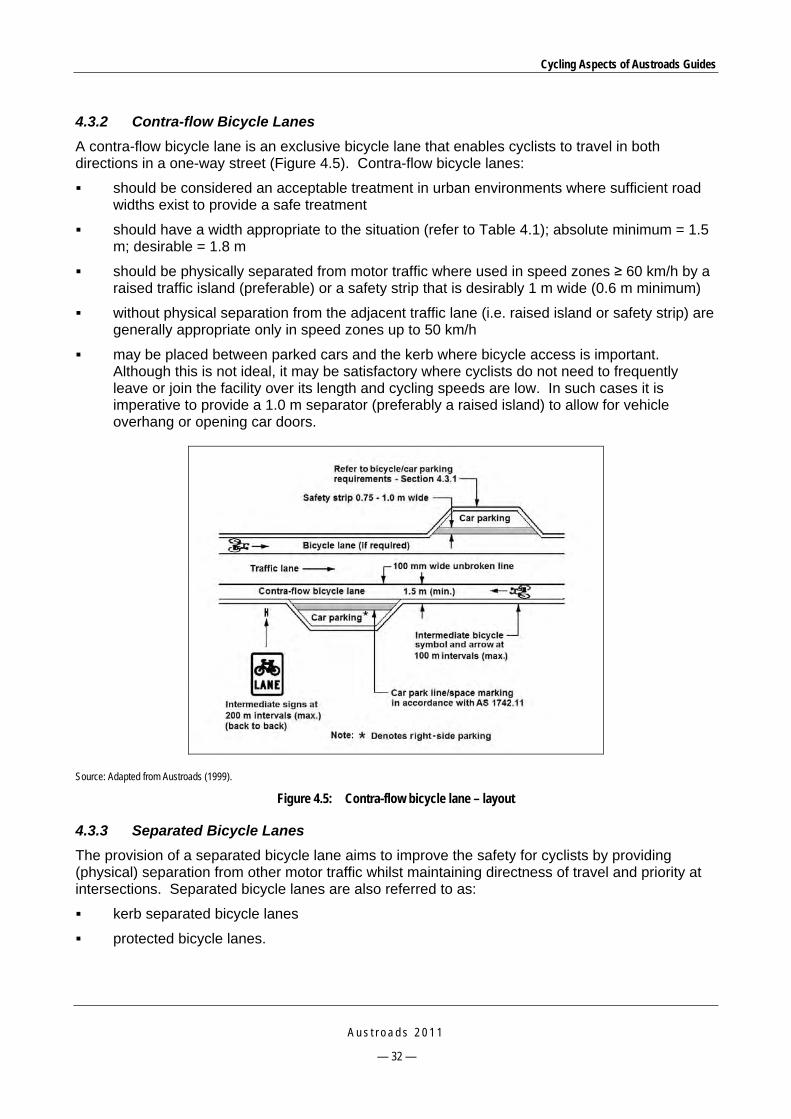
Cycling Aspects of Austroads Guides
A u s t r o a d s 2 0 1 1
— 32 —
4.3.2 Contra-flow Bicycle Lanes
A contra-flow bicycle lane is an exclusive bicycle lane that enables cyclists to travel in both directions in a one-way street (Figure 4.5). Contra-flow bicycle lanes:
should be considered an acceptable treatment in urban environments where sufficient road widths exist to provide a safe treatment
should have a width appropriate to the situation (refer to Table 4.1); absolute minimum = 1.5 m; desirable = 1.8 m
should be physically separated from motor traffic where used in speed zones ≥ 60 km/h by a raised traffic island (preferable) or a safety strip that is desirably 1 m wide (0.6 m minimum)
without physical separation from the adjacent traffic lane (i.e. raised island or safety strip) are generally appropriate only in speed zones up to 50 km/h
may be placed between parked cars and the kerb where bicycle access is important. Although this is not ideal, it may be satisfactory where cyclists do not need to frequently leave or join the facility over its length and cycling speeds are low. In such cases it is imperative to provide a 1.0 m separator (preferably a raised island) to allow for vehicle overhang or opening car doors.
Source: Adapted from Austroads (1999).
Figure 4.5: Contra-flow bicycle lane – layout
4.3.3 Separated Bicycle Lanes
The provision of a separated bicycle lane aims to improve the safety for cyclists by providing (physical) separation from other motor traffic whilst maintaining directness of travel and priority at intersections. Separated bicycle lanes are also referred to as:
kerb separated bicycle lanes
protected bicycle lanes.

Cycling Aspects of Austroads Guides
A u s t r o a d s 2 0 1 1
— 33 —
A separated bicycle lane:
is usually considered where a substantial length of road is being widened or duplicated and where there are few driveways and intersections
generally provides a higher level of service for cyclists and has been shown to promote increased patronage on cycling routes
is an option to be considered where a full width off-road path with suitably high levels of directness and priority for cyclists at intersections cannot be achieved within the existing road reservation.
Kerb separated bicycle lanes
Figure 4.6 illustrates a kerb separated bicycle lane and Figure 4.7 shows an example. Table 4.6 summarises aspects to be considered in the design of this type of lane.
Note:
A one-way crossfall should be applied where a flush concrete strip is used so that drainage does not accumulate on the bicycle path.
Source: Figure 4.20 of Austroads (2010g).
Figure 4.6: Location and typical cross-section of kerb separated bicycle lane

Cycling Aspects of Austroads Guides
A u s t r o a d s 2 0 1 1
— 34 —
Source: Figure 4.21 of Austroads (2010g).
Figure 4.7: Kerb separated bicycle lane
Table 4.6: Considerations in the design of kerb separated bicycle lanes
Aspect Consideration
Operation Are designed to operate one-way, for bicycle use only and are required on both sides of the road.
Separator The treatment is raised above the traffic lanes and is usually situated alongside semi-mountable kerb and channel, unless a flush treatment is required for drainage considerations in which case a 600 mm wide flush kerb or edge strip may be used.
The separation may need to be increased by 1.0 m from the back of the kerb to provide clearance from car doors where kerbside parking is likely to occur.
Transition The treatment should rejoin the road as an exclusive bicycle lane prior to major intersections to provide a conventional level of directness and priority. This should be accommodated by means of a ramp having a grade no steeper than 10%.
Obstructions Consider obstructions such as street lighting and other utility poles, signs, road safety barriers and any other roadside furniture.
Surface Provide a smooth riding surface. Wherever practicable locate drainage pit lids outside of the lane; otherwise construct with (concrete in-filled) cast iron covers to ensure a flush finish.
Pedestrians The lane is widened to operate as a separated bicycle/pedestrian path or be accompanied by a clearly marked separate footpath if pedestrian demands would otherwise result in the mixing of cyclists and pedestrians in the space immediately adjacent to the through traffic lanes.
Bus stops Consider the treatment of both on-road and indented bus stops to provide a safe facility for both cyclists and bus patrons. The separated bicycle lane can be taken around the back of the bus stop or transitioned back onto the road pavement as an exclusive bicycle lane.
Delineation Appropriate signs and pavement markings should be installed to encourage cyclists to use the facility and to discourage pedestrian use.
Source: Summarised from Section 4.8.5 of Austroads (2010g).

Cycling Aspects of Austroads Guides
A u s t r o a d s 2 0 1 1
— 35 —
Separated protected bicycle lanes
A separated protected bicycle lane (Figure 4.8) is a particular form of separated bicycle lane. This treatment:
may be applied in urban areas where parking is prevalent
is characterised by a raised separation strip to physically prevent vehicular access to the bicycle lane and provide clearance for the opening of car doors.
The raised separator generally requires breaks in the kerb to maintain the free drainage of the road (in a retrofit situation) or otherwise a specific drainage system needs to be installed. Frequent maintenance of these bicycle lanes is required to ensure that they do not accumulate debris and litter that would normally be collected by a street sweeper in routine road maintenance. This is important because cyclists using this type of facility are unable to readily deviate around debris (as they could when using a conventional bicycle lane) such as glass, stones, and other objects that could puncture tyres or cause instability of bicycles.
Note:
Example is a typical cross-section constructed in Melbourne with a bicycle lane width of 2 m.
Source: Figure 4.22 of Austroads (2010g).
Figure 4.8: Typical cross-section of a separated protected bicycle lane
4.3.4 ‘Peak Period’ Bicycle Lanes
‘Peak period' bicycle lanes (Figure 4.9) are common on roads designated with clearways. The restriction of parking during peak traffic periods usually coincides with peak cyclist numbers. On roads where the adjoining land use is predominantly residential, the installation of bicycle lanes during peak periods can be a compromise between the adjoining residents' desire for on-street parking and cyclists' need for designated road space. The timing of the parking restrictions to coincide with local school opening and closure times has the additional advantage of providing a separate cycling facility for school children (Austroads 2010g). The treatment may also be appropriate for sections of road that have abutting commercial development.
Peak period bicycle lanes should only be used when no other option is possible. Often the carriageway layout is such that during off-peak periods cyclists have to contend with stressful and potentially hazardous conditions when cars are parked at the kerbside. It is important in the design of the bicycle lane that conditions for cyclists are assessed for different periods of the day, and that the prohibition of parking associated with the lane is effectively enforced.

Cycling Aspects of Austroads Guides
A u s t r o a d s 2 0 1 1
— 36 —
Source: Figure 4.26 of Austroads (2010g).
Figure 4.9: Peak period bicycle lane (i.e. during and outside clearway times)
4.3.5 Protected Two-way lanes
A protected two-way bicycle lane is an exclusive bicycle lane treatment installed on one side of a road carriageway. The treatment utilises the existing road surface and is physically separated from adjacent two-way traffic lanes and may be appropriate where:
origins and destinations are on the same side of the road and as such road crossings can be avoided
there is no choice other than for a treatment within the road reserve in a length generally consisting of paths and where the need for road crossings by cyclists can be avoided
relatively few driveway crossings exist, particularly where the route is used by children
parking demand is low in the area of the treatment, and as a consequence would be removed
the road is wide such that parking is retained adjacent to (but outside of) the bicycle path area. In this instance the facility is regarded as appropriate only where the parking is long-term.
In general, the regulations applying to exclusive bicycle paths, in relation to travelling or stopping in protected lanes, by motor traffic, pedestrians and others, would also be applicable.
4.4 Finding Space for Bicycle Lane Treatments A number of techniques can be used to obtain space in road reserves for the provision of cyclist facilities. These include:
rearrangement of space by:
— adjustment of existing carriageway (narrowing adjacent traffic lanes)
— upgrading service roads
— sealing road shoulders

Cycling Aspects of Austroads Guides
A u s t r o a d s 2 0 1 1
— 37 —
trading space through:
— indented car parking
— restricting car parking
— road widening at the verge
— road widening at the median
— removing a traffic lane
— closing a road
alternative space such as:
— an alternative off-road route.
4.5 Supplementary Road Treatments 4.5.1 Curves and Turns
On the inside of small radii horizontal curves, tight turns and other local area traffic management facilities, cyclists can often be at danger of rear-end/side-swipe collisions from motor vehicles that are travelling too close. The following forms of protection provide safety benefits to cyclists at these locations, and should be considered as part of the application of the various bicycle lane facilities discussed in this guide.
Effective forms of protection include (Section 4.8.12 of Austroads 2010g):
pavement bar island
raised traffic islands
fully mountable kerbing at the left side of the carriageway (to the direction of travel of cyclists), to permit access to the footpath at any point along the length of kerb
closely spaced (e.g. 3 m intervals) raised pavement markers applied outside of bicycle lanes
short lengths of off-road bicycle lanes to bypass pinch points in the cross-section.
A road authority may consider other forms of protection such as enhanced lane markings to improve delineation and separation.
Where treatments take cyclists off the road, care needs to be exercised to ensure that cyclists travelling at speed are not directed out into the traffic stream at the exit point. These treatments should be self-cleaning to avoid the accumulation of debris; otherwise a comprehensive maintenance program will be required.
Designers should also ensure that the safety and other needs of pedestrians are provided for, wherever off-road cycling treatments are proposed.
Cycling Aspects of Austroads Guides
A u s t r o a d s 2 0 1 1
— 38 —
4.5.2 Lane Channelisation
Where there is a need to provide additional protection to or reinforcement of exclusive bicycle lanes, channelisation treatments can be employed. These treatments assist drivers to identify the space for cyclists and help to minimise vehicle ingress into bicycle lanes. Channelisation treatments can consist of:
continuity lines
kerbed projections which also help to guide the path of cyclists to the area of the bicycle lane
rumble (tactile) edge lines
low profile rubber kerbing.
4.6 Ramps Ramps linking a road carriageway and a path located in the area of the roadside verge may be required in association with protection at curves, narrowing at right-turn lanes and path treatments adjacent to roads.
The exit ramp from the road should be oriented to enable the cyclist to leave the road at a speed appropriate to the abutting development and the level of pedestrian usage of the path. The ramp for re-entering the traffic stream should be placed at an angle that enables cyclists to conveniently view traffic approaching in the left-hand lane. Consideration should also be given to providing a kerb extension to shelter the reintroduction of an exclusive bicycle lane.
The gradient of ramps to and from raised path sections should be constructed to avoid an abrupt change of grade (in excess of 5%) and in general should not be steeper than 15:1 where high bicycle speeds are likely. Figure 4.10 provides guidance to assist designers to design ramps for low and high-speed movements.

Cycling Aspects of Austroads Guides
A u s t r o a d s 2 0 1 1
— 39 —
Source: Figure 4.25 of Austroads (2010g).
Figure 4.10: Low and high-speed exit and entry ramps

Cycling Aspects of Austroads Guides
A u s t r o a d s 2 0 1 1
— 40 —
4.7 Road Safety Barriers Cyclists and pedestrians may require a barrier to prevent them inadvertently running onto a traffic lane from an adjacent shared path. In cases where there is no need to protect path users from errant vehicles, or errant vehicles from roadside hazards, a fence of a suitable height for cyclists will be adequate.
Where there is a need to provide a safety barrier between a path and road traffic it is important that the rear of the safety barrier is not a hazard for pedestrians and cyclists. Designers should ensure that:
adequate clearance is provided between the rear of the safety barrier and the path (refer to the Guide to Road Design – Part 6A: Pedestrian and Cyclist Paths [Austroads 2009m])
no sharp edges, burrs or other potential hazards (e.g. protruding bolts) exist
where sufficient clearance cannot be provided, cyclists are protected from ‘snagging’ on posts by the provision of suitably designed rub rails or other appropriate means
where sufficient clearance cannot be achieved, consideration is given to the need to increase the height of the barrier either to prevent errant cyclists from falling over the barrier and into a traffic lane or to discourage pedestrians from jumping over the barrier to cross the road at an unsafe location.
Where sufficient space is available a frangible pedestrian fence may be erected behind the road safety barrier at a distance that would accommodate the likely deflection of the barrier under impact by an errant vehicle. Adequate clearance is also required between pedestrian fences and bicycle paths and shared paths. In situations where space is restricted, it may be necessary to consider provision of a higher rigid barrier.
Designers should ensure that any extension to the height of a barrier would not be detrimental to its performance under vehicle impact or result in components being hazardous to motorists or path users in the event of a crash with the barrier (e.g. horizontal rails spearing vehicles).
Where pedestrian facilities are incorporated behind a road safety barrier system, the desirable minimum height of the barrier is 1200 mm above the surface of the footway. Where provision for pedal cyclists is required, the desirable minimum height above the surface of the path should be 1400 mm.
Access through barriers
Preferred practice is to avoid providing breaks in a safety barrier. However, it may be necessary to consider breaks at locations such as intersections, points of access to property, sites where pedestrians cross the road, and access points in medians. Where breaks are necessary safe end treatments must be provided.
Bridges and overpasses
AS 5100: 2007 provides information on barriers for bicycle and pedestrian bridges and for some design elements for bicycle/pedestrian paths as they relate to bridges.
Temporary barriers and roadworks
During roadwork activities, consideration needs to be given to provision of bike and/or pedestrian access through the works. Other times where provision of temporary barriers may be required include during special events where there is a need to control vehicle and pedestrian movements.

Cycling Aspects of Austroads Guides
A u s t r o a d s 2 0 1 1
— 41 —
4.8 Provision for Cyclists on Freeways 4.8.1 General
The main issue that should be addressed in deciding whether cyclists may use freeways is road safety. The policy with respect to cyclists using freeways varies between jurisdictions. Where cyclists are permitted to use a freeway it is important that they are provided with information, guidance and road conditions which enable them to use it safely. It is inappropriate for cyclists to use the normal traffic lanes of freeways and so the safe use of these facilities by cyclists is predicated on providing:
smooth, debris-free shoulders of adequate width
safe treatments at interchanges
an efficient and safe route within the corridor if cyclists are not permitted to use the freeway (e.g. a high-speed exclusive bicycle path, a shared path or an alternative road route).
Because rural freeways usually have relatively low volumes of traffic leaving and entering at interchange ramps cyclists should normally be allowed to use rural freeways, particularly those having sealed shoulders, provided that information and guidance is given to guide them safely across exit and entry ramps.
The use of urban freeways by cyclists is a matter to be determined by the relevant jurisdiction which may decide to deny cyclists' access to specific freeways because of the difficulties and hazards which would confront them in high-volume, high-speed traffic environments. A number of factors should be considered when assessing the suitability of a freeway and its interchanges for use by cyclists, as summarised in Table 4.7.
Table 4.7: Cyclist use of freeways – factors to consider
Unreasonably hazardous locations Suitability for use
Shoulders which are too narrow Off-ramps and on-ramps which carry very
heavy volumes of high-speed traffic throughout the day and night
Sections of freeway where the shoulders are used as bus lanes to provide a relatively high-speed express bus service
High bridges where prevailing crosswinds and turbulence from large motor vehicles can destabilise cyclists
Weaving areas between entry ramps and exit ramps
Places where vehicles stop in the emergency stopping lane (i.e. shoulder).
The freeway should provide a safer and more convenient route than alternative non-freeway routes.
Potential for use of the freeway by children should be low. Sealed outer shoulders are essential on freeways which carry heavy volumes of motor
vehicles and significant numbers of cyclists. For 100 km/h a 3.0 m width is desirable but a minimum width of 2.0 m may be used. For 80 km/h the corresponding widths are 2.0 m and 1.5 m.
Adequate gaps should be available in ramp traffic to allow safe and convenient crossing by cyclists; otherwise provide an alternative route through or around the interchange.
All ramps should have an outer shoulder at least 1.2 m wide, preferably sealed. Ramps exiting and entering the freeway from the right-hand lane are likely to be
unsuitable for cyclists as they have to cross two lanes of high-speed traffic to access them. Alternative routes have to be examined.
Sight distance in accordance with a pedestrian crossing the road: crossing sight distance (CSD; refer to Guide to road design – Part 4A: Unsignalised and signalised intersections, Austroads 2009i) should be provided at the location where cyclists are directed to cross freeway ramps.
Where very high traffic volumes or difficult geometry would cause serious safety hazards an alternative route or an off-carriageway cycling path may need to be provided.
Source: Summarised from Section 4.6.2 of Austroads (1999).

Cycling Aspects of Austroads Guides
A u s t r o a d s 2 0 1 1
— 42 —
The following guidelines should be considered when planning bicycle lanes on freeways:
Cyclists may be permitted on rural freeways/motorways subject to risk assessments where
— wide, sealed shoulders of freeways provide cyclists adequate clearance from vehicles in the adjacent lane; the shoulder may be marked as a designated bicycle lane
— there is a good quality riding surface
— conflict between motor vehicles and bicycles at entry and exit ramps is minimal or is able to be managed through traffic control or design measures (refer to the Guide to Traffic Management – Part 6: Intersections, Interchanges and Crossings [Austroads 2007] for further information).
The crossing of interchange entry and exit ramps is an aspect of cyclists’ use of freeways/motorways that requires careful consideration. In rural areas sufficient safe gaps in ramp traffic will usually be available. Where volumes are relatively high a traffic assessment based on gap acceptance analysis may be necessary (refer to Ove Arup & Partners 1989). Treatments for ramps are described in Section 5.6.
Road authority policy often bans cyclists from urban freeways.
4.9 Local Area Traffic Management Schemes An underlying principle of LATM is that conditions should be made better for pedestrians and cyclists, by virtue of the intentions of LATM (particularly speed reduction) (Yeates 2000a, b). The consequences of poorly designed LATM schemes are more likely to impact on cyclists than pedestrians.
Factors to consider in regard to cyclists’ use of roads that have LATM treatments are provided in Table 4.8. The content of this table is a summary of Section 8.12 of the Guide to Traffic Management – Part 8: Local Area Traffic Management (Austroads 2008b); practitioners should refer to this section for further guidance on catering for cyclists in local area traffic management schemes.

Cycling Aspects of Austroads Guides
A u s t r o a d s 2 0 1 1
— 43 —
Table 4.8: Factors to consider for cycling in regards to LATM schemes
Aspect Consideration
Principles Cyclist needs should be an integral part of the LATM planning and design process rather than treated as a supplementary or post-design check.
Unless speeds are quite low (say < 30 – 40 km/h) some form of separation for cyclists may be desirable (at least on the designated bicycle network.
Separation is more critical at intersections and at devices that deflect the travel path (e.g. slow points) than at mid-block locations. Mid-block bicycle lanes should be carried through these more critical locations.
On-road lanes are preferred over off-road paths for cyclists in local areas, especially where there is direct access to abutting development as cyclists entering or crossing roads, especially the young, are at increased risk.
Ensure that LATM treatments that narrow the road carriageway width do not create safety problems for cyclists. Lane widths should either be wide enough to allow the safe passage of a cyclist and a vehicle side by side (3.7 m or more)
or narrow enough to permit the passage of a vehicle or bicycle only (3.0 m or less). Widths in between these two extremes create squeeze points and result in conflicts. For a narrow lane width, provide an off-road option for young cyclists.
Design considerations
There are three design issues that the treatment selection and design of LATM should take into account: bicycle/vehicle conflict bicycle/pedestrian conflict cyclist service and comfort. When adapting the traffic environment, keep in mind: the dynamic characteristics of the bicycle and rider, which may vary widely according to age, bike type, experience, skill, etc. the seven broad categories of cyclists and their very specific needs, including primary school children, secondary school
children, recreational cyclists, commuter cyclists, utility cyclists, touring cyclists and sports cyclists in training the sometimes aggressive, and often inconsiderate, attitude of drivers towards cyclists the youth and inexperience of many local street cyclists, who are nevertheless a legitimate part of the traffic system.
General requirements
The following aspects of good LATM design and maintenance are especially important for cyclists: avoid placing speed control devices in isolation position devices sufficiently close together to deter unnecessary acceleration and braking provide bicycle bypasses of devices
— where closely spaced devices could detract from the attractiveness of the route for cyclists — where there is a significant difference in the speed of vehicular and bicycle traffic — where it is desirable to separate cyclists from other traffic — anywhere cycling needs to be encouraged
provide clear signs and visibility provide adequate street lighting aim for a speed environment that is sympathetic to cyclists as well as other road users.
Route continuity
Actively improve bicycle route connectivity and continuity through appropriate LATM design. Provide for cyclists to pass through street closures and other treatments that block some or all motorised traffic movements. Where bicycle routes cross roads ensure that islands and refuges are wide enough to shelter bicycles (i.e. refuge width
3.0 m desirable, 2.0 m desirable minimum and 1.8 m minimum) and provide adequate storage where cyclist crossing volume is high.
Vehicle speeds
The most important contribution to pedestrian and cyclist safety and amenity in local streets comes from effective reduction in vehicle speeds. Aim at speeds below 40 km/h rather than above 50 km/h and a consistently low speed along the route.
Surfaces Ensure surfaces for cyclists are smooth and free of irregularities that would adversely affect stability of bicycles that have narrow tyres.
Maintain areas where debris may accumulate.
Squeeze points
Avoid points where cyclists would be squeezed by motorists. Either separate cyclists from motor vehicles or scale down the roadway so that sharing space is not possible.
Vertical devices
Vertical speed control devices with smooth and gradual surface transitions are generally preferred rather than horizontal devices that create squeeze points. Flat-top road humps with ramps of 1:15 to 1:20 relative to the gradient of the road are generally regarded as ‘bicycle friendly’. Side slopes across the line of travel should not be severe. Transitioned ramps (e.g. sinusoidal humps) are recommended (Webster & Layfield 1998). Greater downhill speeds should be anticipated when considering humps on grades.

Cycling Aspects of Austroads Guides
A u s t r o a d s 2 0 1 1
— 44 —
Figure 4.11 shows an example of a satisfactory bypass of a road hump in a residential street in the City of Booroondara, Victoria, in a situation where the relatively low motor vehicle volume does not justify a bicycle lane along the street. The surface of the bypass is well delineated to improve awareness of cycle use and conflict between cyclists and motor vehicles is unlikely on the departure from the device.
Source: J. Hondrakis – Booroondara City Council.
Figure 4.11: Example of good practice – cycle bypass of a road hump
Continuity of the bicycle/parking lane past treatments is important. Figure 4.12 shows what should not be done. Instead, the island should be positioned closer to the kerb and also offset from the traffic lane so that cyclists have sufficient space to pass between the island and the adjacent traffic lane.
Source: Figure 8.3 of Austroads (2008b).
Figure 4.12: Parked vehicle blocks cycle bypass

Cycling Aspects of Austroads Guides
A u s t r o a d s 2 0 1 1
— 45 —
Figure 4.13 shows an example of good practice to allow bicycles to bypass a half road closure. The bypass is of adequate width and there are no obstructions to sight lines and the pavement surface is smooth.
Source: Figure 8.4 of Austroads (2008b).
Figure 4.13: Cycle bypass at half road closure

Cycling Aspects of Austroads Guides
A u s t r o a d s 2 0 1 1
— 46 —
5 ROAD INTERSECTIONS
5.1 Introduction This section describes issues for cyclists at intersections and presents bicycle treatments for signalised intersections, unsignalised intersections, roundabouts and road crossings. It provides information on treatments which should be adopted, where necessary and practicable, to improve the safety and convenience for cyclists using intersections.
Where a bicycle lane exists or is planned on roads leading up to an intersection the design should assist the safe passage of cyclists through the intersection. In rural areas this may simply require an adequate clearance between the islands and left edge of the road to provide continuity of shoulders through the intersection. In urban areas it will often involve a bicycle lane marked through the intersection.
In catering for the needs of cyclists at intersections designs should conform to the standard approach and principles of traffic engineering design for all road users. This practice seeks to provide traffic facilities which clearly indicate the nature and extent of traffic movements and the potential conflicts. All road users, including cyclists, will benefit from a traffic environment which assists the road user to anticipate potential conflicts and encourages traffic awareness and predictable behaviour.
The types of lanes that may have to be incorporated into traffic routes, and therefore intersections, include:
bicycle lanes
bicycle/car parking lanes
wide kerbside lanes.
These and other types of bicycle lanes are discussed in Section 4 in the Guide to Road Design – Part 3: Geometric Design (Austroads 2010g).
Because of the wide range of ages and ability of cyclists, it is often necessary to accommodate off-road paths for young and/or inexperienced cyclists within intersection layouts.
5.2 Issues at Intersections for Cyclists 5.2.1 General
Common issues faced by cyclists and possible treatments are summarised in Table 5.1. A process to evaluate conflict for cyclists at intersections is provided in the Guide to Traffic Management – Part 6: Intersections, Interchanges and Crossings (Austroads 2007).

Cycling Aspects of Austroads Guides
A u s t r o a d s 2 0 1 1
— 47 —
Table 5.1: Issues for cyclists
Issue Characteristics Treatments
Squeeze points Road narrows and separation between cyclists and motor vehicles reduces.
Non-flush service pit covers, and sumps (New Zealand) that reduce the available width for cyclists.
Local widening(1) or remarking of traffic lanes to achieve a wide kerbside lane (where insufficient width is available for a bicycle lane).
Bicycle lane. Bicycle/car parking lane. Shared path (provide where an on-road
facility is impracticable and for use by young and inexperienced cyclists).
Bicycle path. Add ‘Watch for Bicycles’ sign (AS 1742.9:
2000, sign G9-57). Provide bicycle symbol and short
continuity line in wide kerbside lane to increase motorist awareness of the presence of cyclists and to improve cyclist comfort (not permissible in New Zealand)(2).
Ensure that service covers and drainage assets do not reduce the road width available for safe use by cyclists.
Vehicle overtaking and immediately turning left into side street or driveway
Cyclist may crash into vehicle or have to take risky evasive action.
Bicycle lane to increase awareness(3).
Motor vehicle converge and diverge areas Cyclists are vulnerable when riding through the taper lengths of converge and diverge areas.
Cyclists use left-turn lanes as a refuge from through traffic but cannot legally proceed in the ‘through’ direction if a left-turn arrow is marked in the lane.
Bicycle lane marked continuously throughout road or through converge and diverge areas with a continuity line(4).
Provide green surface treatment for bicycle lane.
Lack of continuity and connectivity Cyclists continually have to rejoin motor vehicle lanes because bicycle lane is terminated at squeeze points, resulting in hazardous movements.
Continuous bicycle lanes through unsignalised intersections where feasible.
Provide green surfacing for bicycle lanes through hazardous areas or complex situations.
If practicable, re-allocate road space used by other road users or for other purposes to achieve bicycle lane continuity.
Erect ‘Watch for Bicycles’ signs at bicycle lane terminations (AS 1742.9: 2000, sign G9-57).
Safely cross or join conflicting flows Insufficient gaps in the traffic stream being crossed or joined.
Signalised cyclist crossing. Refuge island. Well-designed transition from shared path
or bicycle path to an on-road bicycle lane i.e. physical protection for cyclist through alignment of left-side kerb (refer to the Guide to Road Design – Part 4: Intersections and Crossings – General (Austroads 2009h)).

Cycling Aspects of Austroads Guides
A u s t r o a d s 2 0 1 1
— 48 —
Issue Characteristics Treatments
Gaining position to turn right
Unsafe weaving manoeuvres on approach to major intersection.
Space to wait and undertake right-turning manoeuvre.
Difficult conditions turning right.
Provide a bicycle lane on the left side of intersection approach and space for cyclists to store whilst making a ‘hook turn’(5).
Locate a right-turn bicycle lane between the right-turn lane and through lane for motor vehicles (does not assist with weaving on the approach but provides some refuge).
Provide adequate swept paths for cyclists to turn right with other vehicles, especially heavy vehicles including buses.
Provide off-road path on periphery of intersection.
Cyclist not seen by motorists, or cyclist speed misjudged
Cyclist likely to be involved in a crash.
Provide bicycle lanes and logos to increase motorist awareness of the likely presence of cyclists.
Erect ‘Watch for Bicycles’ signs (AS 1742.9: 2000, sign G9-57).
Reduce vehicle speeds through intersection using a physical device.
Loss of access
Road closure or provision of one-way streets could result in loss of access for cyclists.
Provide access for cyclists to pass through local road terminations and pedestrian malls.
Provide contra-flow for cyclists on one-way streets in low speed environments.
1 Local widening or remarking traffic lanes should aim to provide a bicycle lane in the first instance. 2 May not be favoured in some other jurisdictions; check with relevant road authority. 3 Consider the provision of distinctive green surface in bicycle lane. 4 Where a bicycle lane cannot be achieved, install ‘left lane must turn left, bicycles excepted’ signs. 5 Provide cyclist indented storage area on the left side of the road to enable protected right-turn manoeuvre.
Note:
This table provides a summary of key issues for cyclists; however, there are other cycling-related issues for cyclists at intersections (refer to the bicycle safety audit checklist in Appendix D).
Source: Table 3.3 of Austroads (2007).
5.3 Signalised Road Intersections 5.3.1 General
Signalised intersections are often associated with traffic routes and are therefore utilised by commuter cyclists. Wherever practicable, traffic routes and signalised intersections should provide the space and operational conditions to support cycling as a viable alternative mode of transport. The needs of cyclists should be considered in relation to detection, signal phasing and timing, and road space. Off-road paths are often provided for non-commuter cyclists (e.g. the young and novice cyclists) and these paths often have to be incorporated into the functional layouts of signalised intersections. Traffic management considerations for cyclists at intersections are also provided in the Guide to Traffic Management – Part 6: Intersections, Interchanges and Crossings (Austroads 2007).
5.3.2 Traffic Management Guidelines
The following tables provide key traffic management guidelines for consideration when designing signalised intersections. Table 5.2 and Table 5.3 cover cyclist requirements for arterial roads and local roads respectively whilst Table 5.4 covers lane management.

Cycling Aspects of Austroads Guides
A u s t r o a d s 2 0 1 1
— 49 —
Table 5.2: Cyclist requirements for arterial road signalised approaches
Context Guidelines
Bicycle lanes at intersection approach and departure Bicycle lanes should be provided on intersection approaches where: the route is a designated bicycle route bicycle lanes are marked mid-block squeeze points exist for cyclists and it is feasible to develop sufficient space for
the bicycle lane the layout of the intersection results in high traffic volumes or relatively high
speed vehicles weaving across the path of cyclists.
As a guide, consider a bicycle lane where the traffic volume is > 3000 vehicles per day and/or there is a significant percentage of heavy vehicles.
Where appropriate, consider the provision of an exclusive lane for right-turning cyclists, placed between the right-turn lanes and through lanes for motor vehicles. Consideration should also be given to the manner in which right-turning cyclists may gain access to the bicycle lanes.
In Australia, cyclists are generally permitted to undertake a ‘hook turn’ at intersections instead of a conventional right turn (refer to Australian Road Rules and Figure 5.11). This option is often used by cyclists at signalised intersections where they can complete the manoeuvre with a green signal, after waiting at the intermediate corner. Provision of a storage area at the corner is not common; however, additional space may be provided by setting back the pedestrian crosswalk lines and stop line on the intersecting approach. This ‘head start area’ (refer to Section 5.3.5) may be marked with bicycle logos.
Bicycle lanes should be provided on the departure side of intersections where: a bicycle lane exists or is planned along a route cyclists are required to weave through high volumes of traffic merging from the
left (i.e. left-turning traffic joining the route) or high-speed merging traffic.
Intersection stop-line storage On bicycle routes a ‘head start area’ (refer to Section 5.3.5) should be considered, to allow for cyclists to wait at the stop line at a position in advance of the motor vehicles. This facility ensures that cyclists waiting at the red light are visible to the first driver in the queue, particularly drivers of commercial vehicles that may have their view of cyclists impeded by the height of the left door of the vehicle.
Bicycle paths, shared paths and separated paths Where paths exist along a route they should continue through the intersection desirably via shared pedestrian/cyclist crossings that are appropriately marked. The provision of hand rails to assist cyclists to remain mounted whilst waiting for a green signal should be considered.
Source: Table 5.2 of Austroads (2007).

Cycling Aspects of Austroads Guides
A u s t r o a d s 2 0 1 1
— 50 —
Table 5.3: Cyclist requirements for local road signalised approaches
Context Guidelines
Local streets Cyclists are expected to share traffic lanes on local streets (typically less than 3000 vpd) except where the street forms part of a designated bicycle route with marked lanes.
Collector – distributor roads Where sufficient width is available, bicycle lanes should be provided on these roads and at the approaches to signalised intersections.
Source: Table 5.3 of Austroads (2007).
Table 5.4: Lane management at signalised intersections
Context Guidelines
On-road lanes On-road lanes are designated by standard bicycle lane signs (usually located beside the road but sometimes overhead.) However, in New Zealand road markings without signs can define a bicycle lane; refer to Land Transport (Road User) Rule 2004 (New Zealand) and Land Transport New Zealand (2007).
Are generally delineated with a continuous lane line (except in motor vehicle diverge and merge areas where two continuity lines are used) and bicycle logos.
The Australian Road Rules limit motor vehicle travel along a bicycle lane to a distance of 50 m, in order to turn left.
Pavement arrows may be used to define directional use of a bicycle lane (e.g. right-turn arrow in a bicycle lane that is situated between the through lane and right-turn lane for motor vehicles).
A green surface may be provided to enhance the delineation of a lane in relatively hazardous or complex situations.
Source: Table 5.4 of Austroads (2007).
5.3.3 The Six Elements
Figure 5.1 illustrates six elements of a signalised intersection where, ideally, visually separated operating space should be provided. However, where space is constrained and all elements cannot be satisfactorily addressed designers should meet as many of the requirements as possible. Design options for the six elements are shown in Figure 5.2 and Figure 5.3 and additional guidelines are provided in Commentary 3.
Source: Figure 10.6 of Austroads (2010i). RTA (2005).
Figure 5.1: Provision of a bicycle operating space at intersections – the six elements

Cycling Aspects of Austroads Guides
A u s t r o a d s 2 0 1 1
— 51 —
Illustrations of exclusive right-turn lanes for cyclists are shown in this section. However, these right-turn lanes are rarely used and should generally not be provided for cyclists at right-turn treatments on arterial roads or busy traffic routes because of the difficulty and crash risk for cyclists moving from the left of the road on an intersection approach to the centre of the road in order to utilise such treatments. Where right turn bicycle lanes are provided for cyclists it is essential that adequate clearance is provided between motor vehicle swept paths to ensure that opposing right-turning cyclists can operate safely and do not come into conflict with each other.
Exclusive right-turn lanes for cyclists would only be provided where:
it can be demonstrated that the volume of traffic on an arterial road/traffic route is low enough for cyclists to be able to safely access the cyclist right-turn lane, and there is sufficient cyclist demand to justify the facility
the speed environment is very low (e.g. 50 km/h limit) and cyclist demand is significant.
These conditions may exist within the business centres of cities or activity centres and may be associated with particular precincts (e.g. universities or sporting and recreational areas).

Cycling Aspects of Austroads Guides
A u s t r o a d s 2 0 1 1
— 52 —
Source: Figure 10.7 of Austroads (2010i). RTA (2005).
Figure 5.2: Design options for signalised intersections (mid-block, transition and approach)
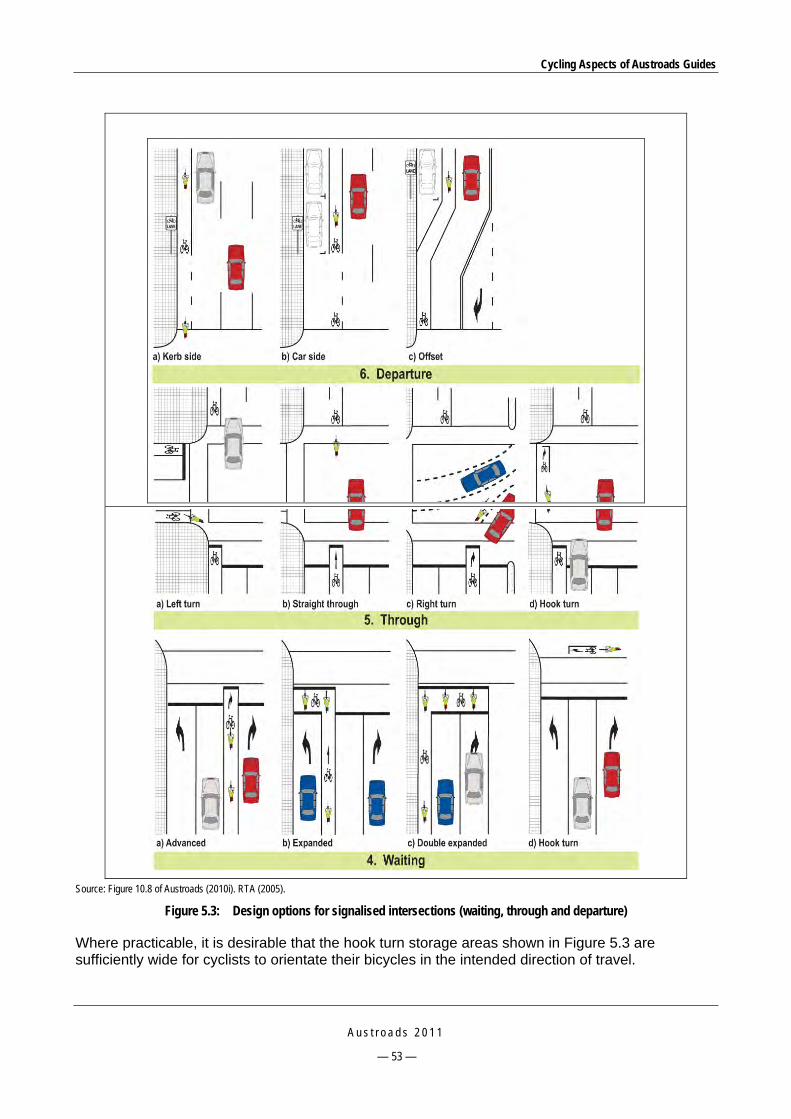
Cycling Aspects of Austroads Guides
A u s t r o a d s 2 0 1 1
— 53 —
Source: Figure 10.8 of Austroads (2010i). RTA (2005).
Figure 5.3: Design options for signalised intersections (waiting, through and departure)
Where practicable, it is desirable that the hook turn storage areas shown in Figure 5.3 are sufficiently wide for cyclists to orientate their bicycles in the intended direction of travel.

Cycling Aspects of Austroads Guides
A u s t r o a d s 2 0 1 1
— 54 —
5.3.4 Bicycle Lanes
Figure 5.4 shows two common examples of bicycle lanes marked at signalised intersections where the width between kerbs is approximately 13 m and parking is provided. In the car-side option no separate left-turn lane is provided for cyclists resulting in them having to make the left turn from the vehicle lane and the expanded storage box. Cyclists using the kerbside option can turn left or proceed straight through the intersection from the bicycle lane. Both options can be applied to bicycle/car parking lanes and exclusive bicycle lanes.
Note: It should be noted that in Figure 5.4(a) conflict may occur between left–turning motor vehicles and cyclists at the entry to the left-turn lane, and in Figure 5.4(b) a similar conflict may occur in the vicinity of the intersection corner.
Source: Figure 10.9 of Austroads (2010i). RTA (2005).
Figure 5.4: Bicycle lanes through signalised intersections – car side and kerbside

Cycling Aspects of Austroads Guides
A u s t r o a d s 2 0 1 1
— 55 —
5.3.5 Head-start and Expanded Storage Areas
These storage areas are provided to position cyclists in a highly visible location while they are waiting to proceed through the intersection, thereby improving safety. Figure 5.5 shows four combinations of head-start and expanded storage areas at signalised intersections. The required length of the head-start area (LHS) varies depending on the number of bicycles that need to be stored. The treatments in each of the four examples can be used in isolation or in any combination. A summary of the various treatments is provided in Table 5.5 .
Note: LHS denotes length of head-start area.
Source: See also Figure 10.10 of Austroads (2010i). Adapted from RTA (2005).
Figure 5.5: Head-start and expanded storage areas

Cycling Aspects of Austroads Guides
A u s t r o a d s 2 0 1 1
— 56 —
Table 5.5: Summary of use of the head-start treatments illustrated in Figure 5.5
Example Purpose Comment
Example (a) The purpose is to store a cyclist in advance of a motor vehicle driver in the adjacent left-turn lane or through lane so that the cyclist can be easily seen by a stationary driver at the stop line.
This is particularly important where the vehicle is a van or truck in which case the cyclist would otherwise be hidden from view below the left-hand side window.
This treatment: reduces the potential for conflict between cyclists and traffic using
the left lane is suitable where cyclist numbers are relatively low allows cyclists to pass on the left side of a queue of vehicles waiting
to turn left has an area that is only as wide as the bicycle lane on the approach has a bicycle stop line that is located 0.2 m in advance of the
pedestrian crosswalk line and 2.0 m (i.e. storage length for one bicycle) beyond the motor vehicle stop line
may be placed to the left of a left-turn lane, a through lane, or a combined through and left-turn lane.
Example (b) This treatment locates the bicycle lane between the left-turn lane and through lane and as a consequence provides additional storage width and length.
Cyclists travelling straight ahead travel to the right of queued or moving left-turning vehicles.
Left-turning vehicles are required to change lanes across the bicycle lane at the start of the left-turn lane.
Cyclists intending to turn left should desirably share the left-turn lane with motor vehicles. However, it is likely that some left-turning cyclists will use the bicycle lane to pass the queue and access the storage box.
Example (c)
This illustration includes two treatments that provide a head start for through cyclists and right-turning cyclists (with expanded storage).
The first treatment is a bicycle lane for cyclists travelling straight through the intersection. In this case left-turning cyclists are expected to share the left-turn lane with motor vehicles.
The second treatment is a right-turn expanded storage area for high volumes of bicycle turning traffic. These treatments: are rarely used and are not intended for use in higher speed zones
(> 60 km/h) because of the difficulty and conflict associated with cyclists crossing traffic lanes to access the right-turn bicycle lane
may be appropriate in lower-speed zones (≤ 60 km/h) where bicycle volumes are high and the turn is made into a single-lane mixed function road that does not have marked bicycle lanes (e.g. inner city areas).
Where bicycle lanes are provided in the intersecting road and bicycle turning volumes are not high, it is more acceptable to install a head-start storage area only in the right-turn bicycle lane. In this instance it is also necessary to include additional turning lines within the intersection to guide right-turning cyclists and delineate the cyclists’ path for drivers.
Example (d) This example also shows two treatments that provide storage expanded across two traffic lanes and a formalised hook-turn treatment.
The first treatment is a hook turn storage area, provided to accommodate cyclists in a safe position while they are waiting for a green traffic signal phase for the intersecting road, and can be used generally throughout the road system.
The second treatment, an expanded storage area shared by left-turning, through and right-turning cyclists is suitable only for lower speed areas (e.g. 50 km/h).
Source: Summarised from Section 10.6.4 of Austroads (2010i).

Cycling Aspects of Austroads Guides
A u s t r o a d s 2 0 1 1
— 57 —
In high traffic locations or where the number of bicycle turning movements is significant, or compliance by motor vehicle drivers is poor (i.e. encroachment into bicycle storage area) it may be necessary to improve the delineation of the storage area by paving it with a green surface. It should be noted that:
not all jurisdictions use head-start areas across multiple lanes, particularly through lanes
a head-start area may be used where there is no bicycle lane on the intersection approach.
The treatment in Example (a) is not suitable for use where a green left-turn arrow is provided on the approach as the treatment encourages cyclists to store at the stop line. Even without the treatment left-turn phases are problematic for through cyclists waiting in the vicinity of the stop line. The bicycle lane for the through cyclist movement depicted in Example (c) can remove this conflict and should be used where a left-turn phase is provided.
In practice many cyclists intending to turn right ride to the left of motor vehicles which are turning or intending to turn right in order to avoid conflict with this traffic stream. This means that they may be exposed to conflict with through motor traffic. The right-turn bicycle lane shown in Example (c) creates space for cyclists, providing protection from moving motor vehicles and enabling cyclists to easily advance to the head of the right-turning queue.
If the volume of cyclists is high then consideration may be given to providing a larger storage area as shown in Examples (c) and (d).
5.3.6 Hook Turn Storage Boxes and Hook Turn Restrictions
Under the Australian Road Rules, cyclists on an approach at a signalised intersection can use a hook turn as an alternative to a conventional right turn from the centre of the road. Cyclists undertake a hook turn by travelling straight at the intersection and waiting at the far corner of the intersecting road. Where the aim is to encourage the use of hook turns, or to ban a conventional right turn that may be hazardous to cyclists, a hook turn storage box can be provided as illustrated in Figure 5.5 (d) and Figure 5.6.
The hook turn box should not be located as illustrated if the left-turn lane has a signalised left-turn arrow. In this case the box may be placed in front of the adjacent lane if the signal phasing permits. Additional in-ground signal detection in the hook turn box should be considered where the box is placed at a side street approach to a major road to ensure that cyclists can call a phase.
It should be noted, however, that the box turn may be illegal in some states and the traffic signal phasing at some intersections may not suit a hook turn. For instance, waiting cyclists who have performed the first stage of a hook turn manoeuvre could be in conflict with an exclusive left-turn phase for the intersecting road (in which case the box should be located to avoid this conflict; refer to notes under Figure 5.6) or a diagonal pedestrian crossing phase.

Cycling Aspects of Austroads Guides
A u s t r o a d s 2 0 1 1
— 58 —
Notes:
In this case the hook turn box is located in the area between the crossing line or vehicle stop line and the crossroad kerb line.
The hook turn box should not be located in this position if the left lane has a signalised turn phase. In this case the bay may be located in front of the adjacent traffic lane if signal phasing permits.
Additional in-ground signal detection should be installed in hook turn boxes where the box is located at a side street entrance to a major arterial road with signal priority.
Source: Figure 10.11 of Austroads (2010i). RTA (2005).
Figure 5.6: Bicycle hook turn box detail
5.3.7 Left-turn Treatments
It is often necessary to provide bicycle lanes as part of channelised left-turn treatments (CHL). High-entry angle or free-flow left-turn treatments may be provided at signalised intersections and bicycle lanes may be required within the layout to provide convenient and safer operating space for cyclists.
High-entry angle treatment
The treatment is illustrated in Figure 5.7 where a bicycle lane provides separation for cyclists through the diverge area on the approach to the intersection and at the stop line. The bicycle lane provides an offset to the island nose and the side of the island is parallel to the adjacent traffic lane. Generally cyclists share the left-turn lane with motor vehicles; however, where the volume of left-turning cyclists is high it may be appropriate to provide a bicycle lane within the left-turning roadway. If a significant number of cyclists turn left at a CHL treatment then provision of a bicycle lane adjacent to the kerb within the left-turn roadway should be considered.

Cycling Aspects of Austroads Guides
A u s t r o a d s 2 0 1 1
— 59 —
Source: Figure 8.15 of Austroads (2010i).
Figure 5.7: Provision for cyclists at a signalised CHL treatment in a low-speed environment
Free-flow CHL treatment
Figure 5.16 in Section 5.4.3 illustrates a free-flow left-turn island at an unsignalised intersection that incorporates a treatment designed to discourage cyclists from travelling in a path between the auxiliary lane and the adjacent through lane and being caught between through traffic and merging traffic. The layout shown can be readily adapted to a signalised intersection by providing stop lines, pedestrian crosswalk lines, pedestrian ramps, continuity lines for that portion of the bicycle lane within the intersection and probably a signalised crossing of the left-turn roadway.
Left-turn bypass treatment
Left-turn access through signals may be provided for cyclists where a major bicycle route turns left through a signalised intersection as shown in Figure 5.8. This treatment has a bicycle lane in the intersecting road. Where there is no bicycle lane in the intersecting road the bypass should be designed as a free-flow arrangement where the bicycle lane is directed into an off-road path parallel to the intersecting road to join it with a protected transition (kerb extension).

Cycling Aspects of Austroads Guides
A u s t r o a d s 2 0 1 1
— 60 —
Source: Figure 10.12 of Austroads (2010i). RTA (2005).
Figure 5.8: Bicycle lane left-turn bypass at a signalised intersection
5.3.8 Bypass of T-intersection
In order to limit the delay to cyclists at T-intersections, circumstances may permit the construction of a bypass of the intersection for cyclists opposite the discontinuing leg of an intersection, as shown in Figure 5.9. The bypass may be separated by channelisation as shown or a separated path treatment can be used where the bicycle path is raised and adjacent to the footpath. A disadvantage of the channelised treatment may be the accumulation of debris and the consequent maintenance. Use of the treatment is covered in the Guide to Road Design – Part 4A: Unsignalised and Signalised Intersections (Austroads 2010i).

Cycling Aspects of Austroads Guides
A u s t r o a d s 2 0 1 1
— 61 —
Source: Figure 10.13 of Austroads (2010i).
Figure 5.9: Cyclist bypass lane at a signalised T-intersection
5.3.9 Crossings at Signalised Intersections
General
It is often necessary to integrate off-road bicycle facilities with other road user requirements at signalised intersections. The design should ensure that the movements of cyclists are managed and regulated to ensure the safe interaction of cyclists with pedestrians and motor vehicles.
The facility to be integrated may be a shared path, an exclusive bicycle path, or a separated path. Where a shared path passes through an intersection cyclists are expected to share the marked foot crossing with pedestrians. Where a bicycle path or a separated path is to be accommodated the cyclists and pedestrians will usually be separated on the crossing.
Separated path crossing
Figure 5.10 shows an example of a multi-lane road intersection with off-road bicycle paths on one road and a shared path on the other road in a constrained road reservation. In this case the various paths adjoin and cross parallel to the intersecting roads. This example shows two-way bicycle paths on both sides of one road and shared paths on both sides of the intersecting road. For this type of treatment it is desirable to have separate detection and lanterns for cyclists and pedestrians (see Guide to Traffic Management – Part 9: Traffic Operations (Austroads 2009d).

Cycling Aspects of Austroads Guides
A u s t r o a d s 2 0 1 1
— 62 —
Notes:
Only the additional bicycle signal lamps are shown, not the complete traffic signal layout.
In-path or other remote detection is recommended for bicycle paths.
The width of the marked crossing for separated paths should match the width of the paths on the approach.
At intersections where the volume of cyclists and pedestrians is high it is advisable to provide contrasting surfaces to delineate the use and priority of movement.
Source: Figure 9.6 of Austroads (2010i). Adapted from RTA (2005).
Figure 5.10: Shared path and two-way bicycle path at a signalised intersection
Where off-road bicycle routes are required to pass through major intersections, signal control should be considered for left-turn slip lanes. The designer should aim to provide a similar level of service through the intersection for cyclists as for motor vehicles. Desirably the signal phasing and timing should enable cyclists to pass through the intersection in one stage. Where practicable pedestrian and cyclist crossings should be separated; however, where this is not possible cyclists will have to share the crossing with pedestrians.
It is important that:
the design and markings are designed to minimise conflict between cyclist and pedestrians
where appropriate, bicycle detection loops are provided
where provided, bicycle activation buttons (similar to pedestrian buttons) are located in a convenient position close to the crossing approach or holding line
adequate queuing and storage space is provided for cyclists
additional width is allowed for cyclists starting up at the signals.

Cycling Aspects of Austroads Guides
A u s t r o a d s 2 0 1 1
— 63 —
Right turns from off-road bicycle paths
The treatment shown in Figure 5.11 is similar to that used at large signalised intersections to assist bicycle hook turns between a separated path and a bicycle lane on the intersecting road. Up to four bicycles can be accommodated in this area while waiting for a green right-turn arrow. If the cyclist volume is high, green pavement surfacing should be considered on both the holding area and the bicycle crossing.
Source: Figure 9.7 of Austroads (2010i). Adapted from RTA (2005).
Figure 5.11: Right turn from an off-road bicycle path to an on-road bicycle lane
5.3.10 Signalised Mid-block Crossings
Road crossings for cyclists can be coordinated with signalised or unsignalised pedestrian crossings and school crossings. Cyclists are usually required by law to dismount at formal pedestrian crossings including school crossings. Where a bicycle route crosses a road at a signalised crossing care should be taken to ensure that activation buttons are located to avoid the need for cyclists to cross in front of oncoming path users and are within easy reach for a mounted cyclist. Induction loops can also be installed to facilitate detection.
Bicycle crossing lights (i.e. displaying bicycle symbols) should be provided where the crossing serves both pedestrians and cyclists provided jurisdictional traffic regulations permit this treatment.

Cycling Aspects of Austroads Guides
A u s t r o a d s 2 0 1 1
— 64 —
Where road rules permit, a green bicycle signal allows cyclists to ride across the crossing. Where pedestrian and cyclist demands are both heavy there is a tendency for pedestrians to move to the front and block the progress of cyclists using the crossing. In such cases consideration should be given to segregating cyclists and pedestrians as shown in Figure 5.12 (i.e. separate and well-delineated crosswalks for pedestrians and cyclists).
The appropriate type of crossing should be determined with reference to normal warrants for pedestrian crossings using the combined cyclist and pedestrian demand.
Note: The intent of the green surfacing is to improve the discipline of cyclists and pedestrians in using their respective areas of the crossing. However, the delineation of the crossing, and hence the use of green surfacing, is a matter for the relevant road authority.
Source: Figure 9.5 of Austroads (2009h).
Figure 5.12: Signalised crossing with separate pedestrian and cyclist areas
5.4 Unsignalised Road Intersections 5.4.1 General
This section covers treatments designed to assist cyclists to safely negotiate unsignalised intersections between two roads or between a road and a bicycle path or shared path. However, path terminal treatments are not included as they are discussed in the Guide to Road Design – Part 6A: Pedestrian and Cyclist Paths (Austroads 2009m).

Cycling Aspects of Austroads Guides
A u s t r o a d s 2 0 1 1
— 65 —
5.4.2 Basic and Channelised Intersections
Figure 5.13 and Figure 5.14 respectively illustrate the provision of bicycle lanes through basic and channelised intersection treatments for urban situations. The Guide to Road Design – Part 4A: Unsignalised and Signalised Intersections (Austroads 2010i) provides further information and examples on the integration of bicycle facilities into unsignalised intersections. The most important requirements are that the bicycle lanes should be continuous through the intersection and be well delineated as a space for cyclists by appropriate placement of pavement logos, and use of a green surfacing where necessary (e.g. in complex treatments or high-risk situations).
Note: Arrows indicate movements relevant to the turn type. They do not represent actual pavement markings.
Source: Figure 4.2 of Austroads (2010i).
Figure 5.13: Urban basic (BA) intersection turn treatments

Cycling Aspects of Austroads Guides
A u s t r o a d s 2 0 1 1
— 66 —
Note: Arrows indicate movements relevant to the turn type. They do not represent actual pavement markings.
Source: Figure 4.8 of Austroads (2010i).
Figure 5.14: Urban channelised (CH) intersection turn treatments
Bicycle lane treatments through intersections could also be considered at locations where cyclists would be at risk due to the geometric design requirements for motor vehicles. A short, marked bicycle lane through an intersection may provide safety advantages to cyclists provided that its termination point does not lead cyclists into an unsafe situation. Terminating at a sealed shoulder or in a wide kerbside lane would normally deliver adequate safety.

Cycling Aspects of Austroads Guides
A u s t r o a d s 2 0 1 1
— 67 —
5.4.3 Channelised Left-turn Treatment
Figure 5.15 shows a bicycle lane passing through a channelised left-turn (CHL) treatment at an unsignalised intersection. The treatment may be provided to give cyclists priority through diverge areas and hence minimise conflict between cyclists and left-turning motor vehicles.
On priority cycling routes where there are long deceleration or acceleration tapers, large radius curves and high speeds, it is particularly desirable that a bicycle lane be marked through the diverge areas and merge areas. These treatments provide space for cyclists and also warn drivers of the possible presence of a cyclist.
Notes:
Bicycle lanes on priority road must be continuous through unsignalised intersections and connect to bicycle facilities on the approach and departure.
In cases where a bicycle route turns the corner bicycle lanes may be accommodated within the minor road and within the left-turn roadway.
Green pavement surfacing may be used where high numbers of cyclists and motor vehicles interact. Where this is not the case normal surfacing, road markings and bicycle logos may be used to delineate the bicycle lane.
A minimum width of 5.0 m is required in the left-turn slip lane to enable vehicles to pass a disabled vehicle by mounting the semi-mountable kerb. It is therefore necessary to have a solid surface immediately behind the kerbs.
Source: Figure 8.14 of Austroads (2010i).
Figure 5.15: Provision for cyclists at an unsignalised CHL treatment in a low-speed environment
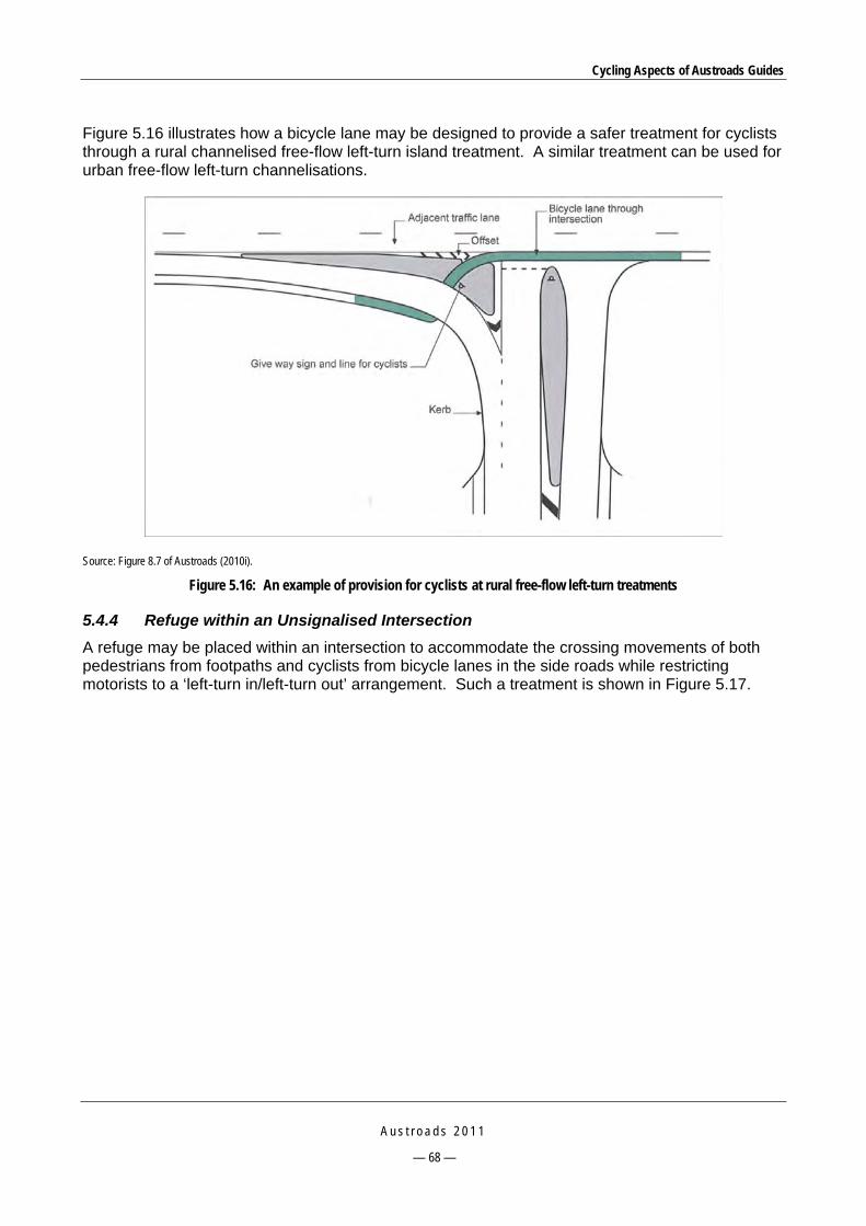
Cycling Aspects of Austroads Guides
A u s t r o a d s 2 0 1 1
— 68 —
Figure 5.16 illustrates how a bicycle lane may be designed to provide a safer treatment for cyclists through a rural channelised free-flow left-turn island treatment. A similar treatment can be used for urban free-flow left-turn channelisations.
Source: Figure 8.7 of Austroads (2010i).
Figure 5.16: An example of provision for cyclists at rural free-flow left-turn treatments
5.4.4 Refuge within an Unsignalised Intersection
A refuge may be placed within an intersection to accommodate the crossing movements of both pedestrians from footpaths and cyclists from bicycle lanes in the side roads while restricting motorists to a ‘left-turn in/left-turn out’ arrangement. Such a treatment is shown in Figure 5.17.
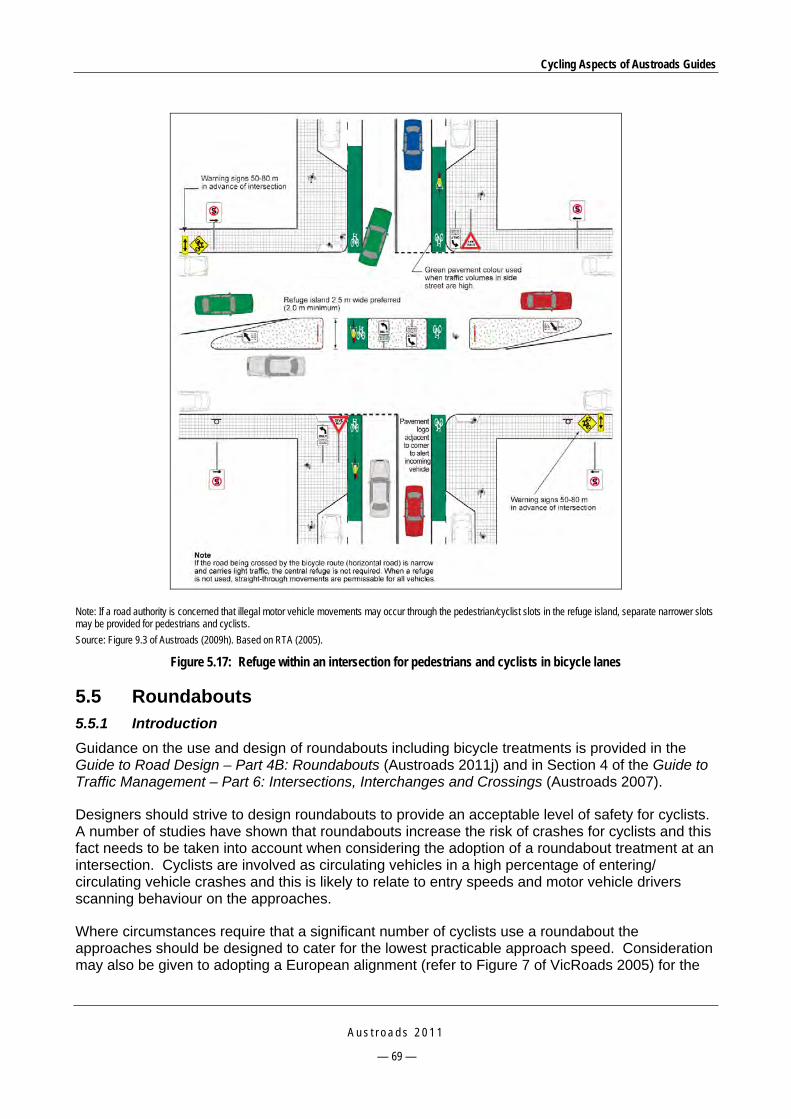
Cycling Aspects of Austroads Guides
A u s t r o a d s 2 0 1 1
— 69 —
Note: If a road authority is concerned that illegal motor vehicle movements may occur through the pedestrian/cyclist slots in the refuge island, separate narrower slots may be provided for pedestrians and cyclists.
Source: Figure 9.3 of Austroads (2009h). Based on RTA (2005).
Figure 5.17: Refuge within an intersection for pedestrians and cyclists in bicycle lanes
5.5 Roundabouts 5.5.1 Introduction
Guidance on the use and design of roundabouts including bicycle treatments is provided in the Guide to Road Design – Part 4B: Roundabouts (Austroads 2011j) and in Section 4 of the Guide to Traffic Management – Part 6: Intersections, Interchanges and Crossings (Austroads 2007).
Designers should strive to design roundabouts to provide an acceptable level of safety for cyclists. A number of studies have shown that roundabouts increase the risk of crashes for cyclists and this fact needs to be taken into account when considering the adoption of a roundabout treatment at an intersection. Cyclists are involved as circulating vehicles in a high percentage of entering/ circulating vehicle crashes and this is likely to relate to entry speeds and motor vehicle drivers scanning behaviour on the approaches.
Where circumstances require that a significant number of cyclists use a roundabout the approaches should be designed to cater for the lowest practicable approach speed. Consideration may also be given to adopting a European alignment (refer to Figure 7 of VicRoads 2005) for the

Cycling Aspects of Austroads Guides
A u s t r o a d s 2 0 1 1
— 70 —
approaches whereby traffic enters at an approach angle that is approximately perpendicular to the central island (i.e. minimal flare).
Reducing the relative speed between entering and circulating vehicles, minimising the number of circulating lanes, and maximising the distance between approaches reduces the entering/ circulating vehicle accident rates at roundabouts and should also minimise entering/circulating vehicle crashes involving cyclists. Therefore, the design concepts given in the Guide to Road Design – Part 4B: Roundabouts (Austroads 2011j) to minimise entry speeds should also minimise accidents involving cyclists.
The benefit of the treatments suggested in this section to improve the situation for cyclists at roundabouts has not necessarily been confirmed through appropriate studies. However, in the absence of such information they are generally considered to provide an advantage in that they allocate space to cyclists and/or raise motorists’ awareness that cyclists may be present on the road.
The results of various studies indicate that a separated cycle path, located outside the circulating carriageway, is the safest design when there are high vehicle flows. However, on designated bicycle routes that cater for commuter cyclists consideration should be given to the provision of signalised intersections instead of roundabouts.
At small single-lane roundabouts on local streets where the geometry encourages very low approach speeds (e.g. 20 km/h) cyclists should be able to safely share the road with general traffic. At larger single-lane or multi-lane roundabouts where speeds are higher, consideration should be given to treatments that assist young or inexperienced cyclists as well as commuter cyclists, namely:
an off-road bicycle path around the roundabout with uncontrolled cyclist/pedestrian movement across each approach leg – there is some evidence to suggest that this is the safest design, at least where traffic flows are high
an on-road bicycle lane to improve drivers’ awareness of the possible presence of cyclists and to provide some separation for cyclists from motor vehicles within the roundabout.
Where a bicycle path or shared path is provided around a roundabout, the intersection between the path and road should be designed to ensure that pedestrians and cyclists are able to safely cross the road and enter any bicycle lanes that may exist on the roundabout approaches and departures (Figure 5.27 and Figure 5.28).
A number of jurisdictions do not favour the provision of bicycle lanes on the approach to, and around the periphery of, roundabouts. Designers should clarify the policy of local jurisdictions before considering the application of cycle lanes at roundabouts. The matter is under review by the Austroads Road Design Review Panel and other key stakeholders including cycling organisations and road safety practitioners. Further advice will be issued in due course.
The extent to which special geometric treatments and/or traffic control measures are needed will depend on the:
daily vehicle traffic volume and the peak-hour flows
proportion of cyclists in the total traffic stream
functional classification of the roads involved
overall traffic management strategies for the location.

Cycling Aspects of Austroads Guides
A u s t r o a d s 2 0 1 1
— 71 —
Specific provision for cyclists is not generally required at single-lane roundabouts on local streets where vehicle speeds are low (i.e. ≤ 50 km/h) and traffic volumes are low (i.e. ≤ 3000 vpd).
Conventional right-turning manoeuvres at multi-lane roundabouts are a problem for cyclists because of the nature of their interaction with motorised traffic. However, under the Australian Road Rules cyclists may undertake a hooked right turn. This requires cyclists to give way to traffic exiting the roundabout and therefore provision of a storage area (i.e. refuge) may be considered on the left side of exits where cyclists can wait for a gap in the exiting traffic.
Other situations where special consideration of cyclists and treatments is required to assist access and safety include:
at roundabouts used by cyclists or where a safety problem has developed, consideration should be given to the provision of signs and/or markings to warn motorists to look for and give way to cyclists moving around the roundabout
a path to provide a bypass of three-legged roundabouts for cyclists travelling across the top of a T-intersection (Figure 5.18)
on approaches where provision of a left-turn slip lane on the corner of a roundabout is necessary, sometimes due to the skew of an intersection (e.g. a marked bicycle lane may be required as shown in Figure 5.19)
where a major motor vehicle movement is able to bypass the roundabout at speed.
Notes:
Smooth ramps provided for cyclists to move from the bicycle lane to the path and return to the bicycle lane.
Path provides a safer treatment across the top of the roundabout.
Source: Austroads (2011j).
Figure 5.18: Roundabout at a T-intersection – path connecting bicycle lanes

Cycling Aspects of Austroads Guides
A u s t r o a d s 2 0 1 1
— 72 —
Source: Figure 5.11 of Austroads (2009j).
Figure 5.19: Bicycle lane continuing past a left-turn slip lane at a roundabout (some jurisdictions may not favour this treatment – see previous text in this Section)
5.5.2 Local Roads – No Bicycle Facility
Local roads provide access for cyclists across the road network. They typically comprise roads that have low traffic speeds (< 50 km/h) and relatively low volumes (< 3000 vpd). These traffic conditions generally enable cyclists to safely share the road with other traffic. Figure 5.20 shows an example of a low-volume single-lane roundabout which is based on cyclists occupying the approach lane. The approach-lane width should not exceed 3.0 m as wider lanes may encourage risky overtaking behaviour by motorists.
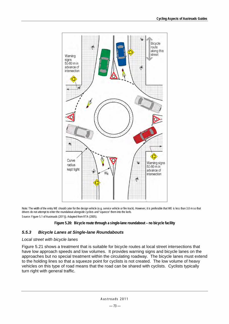
Cycling Aspects of Austroads Guides
A u s t r o a d s 2 0 1 1
— 73 —
Note: The width of the entry WE should cater for the design vehicle (e.g. service vehicle or fire truck). However, it is preferable that WE is less than 3.0 m so that drivers do not attempt to enter the roundabout alongside cyclists and ‘squeeze’ them into the kerb.
Source: Figure 5.1 of Austroads (2011j). Adapted from RTA (2005).
Figure 5.20: Bicycle route through a single-lane roundabout – no bicycle facility
5.5.3 Bicycle Lanes at Single-lane Roundabouts
Local street with bicycle lanes
Figure 5.21 shows a treatment that is suitable for bicycle routes at local street intersections that have low approach speeds and low volumes. It provides warning signs and bicycle lanes on the approaches but no special treatment within the circulating roadway. The bicycle lanes must extend to the holding lines so that a squeeze point for cyclists is not created. The low volume of heavy vehicles on this type of road means that the road can be shared with cyclists. Cyclists typically turn right with general traffic.

Cycling Aspects of Austroads Guides
A u s t r o a d s 2 0 1 1
— 74 —
Source: Figure 5.2 of Austroads (2011j). Adapted from RTA (2005).
Figure 5.21: Bicycle lane at a small single-lane roundabout on a local road (some jurisdictions may not favour this treatment – see Section 5.5.1)
Collector road or arterial road with physical separation of bicycle lanes
Where bicycle routes pass through single-lane roundabouts that have relatively high traffic volumes and moderate speeds, a marked bicycle lane may be provided within the roundabout as shown in Figure 5.22. The circulating bicycle lane should have a contrasting surface that provides cyclists with separate space and comfort but no special priority. However, advance warning signs, a contrasting surface and bicycle pavement logos should be provided to ensure that the facility is highly visible and warns motorists of the likely presence of cyclists. Cyclists passing straight through the roundabout or turning left will remain in the bicycle lane. Cyclists may turn right with general traffic or undertake a hook turn from the left side of the exit. As the islands separating cyclists from motor vehicles are narrow in this treatment it is most important that they are provided

Cycling Aspects of Austroads Guides
A u s t r o a d s 2 0 1 1
— 75 —
with a high standard of delineation (e.g. narrow retro-reflective signs on all noses facing traffic approaching the roundabout and departing from the roundabout).
Notes:
BD = 1.5 m; BA = 1.25 m; VA = entry width to suit design vehicle; VD = exit width to suit design vehicle.
Holding line to extend across entire entry including bicycle lane.
Source: Adapted from RTA (2005).
Figure 5.22: Two bicycle routes crossing at a single-lane roundabout with physically separated bicycle lanes (some jurisdictions may not favour this treatment – see Section 5.5.1)
Collector road or arterial road with no physical separation of bicycle lanes
The treatment shown in Figure 5.23 has been adopted and implemented by some road authorities. It provides a bicycle lane on the roundabout approaches and departures without any physical separation. It is known that many motorists will cut across the bicycle lane on the entry and exit curves when no cyclists are present. For this reason, the maximum entry path radius criteria should be applied by assuming drivers will cut across the bicycle lane.
There is some concern that this treatment may lead to conflict between heavy vehicles and bicycles where the route carries a relatively high volume of both freight vehicles and cyclists. It is therefore suggested that the entries of these treatments should be designed so that the swept paths of entering design vehicles do not have to encroach into the bicycle lane. However, where a site has low volumes of both trucks and bicycles, encroachment may be allowed if necessary to achieve the maximum entry radius criteria.

Cycling Aspects of Austroads Guides
A u s t r o a d s 2 0 1 1
— 76 —
Source: Figure 5.4 of Austroads (2011j). Adapted from VicRoads (2005).
Figure 5.23: Two bicycle routes crossing at a single-lane roundabout with no physical separation of bicycle lanes (some jurisdictions may not favour this treatment – see Section 5.5.1)
5.5.4 Multi-lane Roundabouts on Arterial Roads
Multi-lane roundabouts usually carry high traffic volumes and have higher entry speeds than local street roundabouts and therefore create safety problems for cyclists. It is anticipated that only experienced cyclists will use this type of roundabout and whilst they may feel reasonably comfortable in selecting a gap and turning left and travelling straight through a multi-lane roundabout in the bicycle lane, they will generally find the right-turning manoeuvre challenging. Some cyclists will therefore bypass the right turn by using local streets, shared paths at the roundabout (where provided) or by undertaking a hook turn at the exit.
There is currently no treatment that would assist cyclists to turn right safely through a multi-lane roundabout. However, the provision of bicycle lanes within multi-lane arterial road roundabouts is considered to offer some advantages to cyclists in that these lanes:
heighten the awareness of motorists approaching the roundabout that cyclists may be present
provide designated space on the circulating carriageway and thereby assist experienced cyclists to negotiate the through movement
assist cyclists to undertake a hook turn (right turn) as described in the Australian Road Rules.
Some jurisdictions may prefer not to provide the islands between the bicycle lane and the adjacent traffic lanes at multi-lane roundabouts. Where a multi-lane roundabout carries high volumes of both heavy vehicles and bicycles it is recommended that the bicycle lane should be physically separated from the general traffic lanes on the approaches as illustrated in Figure 5.24. Designers should design the island in accordance with the normal design principles for traffic islands (Section 10, Guide to Road Design – Part 4: Intersections and Crossings – General (Austroads 2009h)). Figure 5.25 and Figure 5.26 show suggested details of the separation islands which are similar in principle to a pedestrian and cyclist refuge island.

Cycling Aspects of Austroads Guides
A u s t r o a d s 2 0 1 1
— 77 —
Source: Figure 5.5 of Austroads (2011j).
Figure 5.24: Bicycle lanes at a two-lane roundabout with physical separation for cyclists (some jurisdictions may not favour this treatment – see Section 5.5.1)
Source: Figure 5.6 of Austroads (2011j).
Figure 5.25: Details of an island on a multi-lane roundabout entry to separate cyclists and motorists (some jurisdictions may not favour this treatment – see Section 5.5.1)

Cycling Aspects of Austroads Guides
A u s t r o a d s 2 0 1 1
— 78 —
Source: Figure 5.7 of Austroads (2011j).
Figure 5.26: Details of an island on a multi-lane roundabout exit to separate cyclists and motorists (some jurisdictions may not favour this treatment – see Section 5.5.1)
5.5.5 Bicycle Paths and Shared Paths at Roundabouts
Bicycle paths or shared paths may be provided adjacent to roundabouts to provide safe passage for inexperienced cyclists and pedestrians. At sites where there is a relatively small volume of pedestrians and cyclists the treatment in Figure 5.27 with normal kerb ramps will suffice.
Source: Figure 4.6 of Austroads (2011j).
Figure 5.27: Path at a roundabout where cyclist and pedestrian volumes are low to moderate

Cycling Aspects of Austroads Guides
A u s t r o a d s 2 0 1 1
— 79 —
Where a shared path is provided at a multi-lane roundabout and bicycle lanes exist on the approach, the crossing treatment shown in Figure 5.28 may be used. This treatment provides a crossing at road level as well as convenient connections between the bicycle lanes and the paths to encourage cyclists to use the shared path to negotiate the roundabout. It is also possible to modify this treatment so that the bicycle lane passes through the roundabout, thereby providing an option for cyclists to remain on the road or to utilise the shared path and road crossings. The treatment in Figure 5.28 also suggests that cyclists using the shared path crossings should be controlled by give-way signs.
Source: Figure 4.8 of Austroads (2011j). Adapted from VicRoads (2005).
Figure 5.28: Crossing detail for a shared path adjacent to a multi-lane roundabout
5.6 Interchanges 5.6.1 General
Issues and the general provisions for cyclists on freeways are covered in Section 4.8. This section provides some further information on options for dealing with cyclist movements at interchanges.
5.6.2 At-grade Treatment at Interchanges
At interchanges, the route to be provided for cyclists should be established and clearly signed. Cyclists should only be permitted to pass through interchanges via at-grade crossings of ramps where sufficient gaps exist in traffic flows to enable cyclists to safely cross the ramps. For additional guidance refer to Section 14 of the Guide to Road Design – Part 4C: Interchanges (Austroads 2009k).
Where cyclists are permitted to pass through an interchange using at-grade crossings of ramps the desirable route should be clearly marked and signed as shown in Figure 5.29.
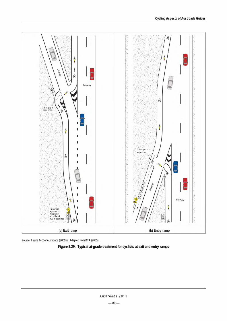
Cycling Aspects of Austroads Guides
A u s t r o a d s 2 0 1 1
— 80 —
Source: Figure 14.2 of Austroads (2009k). Adapted from RTA (2005).
Figure 5.29: Typical at-grade treatment for cyclists at exit and entry ramps

Cycling Aspects of Austroads Guides
A u s t r o a d s 2 0 1 1
— 81 —
5.6.3 Grade Separation of Ramps for Cyclists
Grade separation of cyclist movements across exit and entry ramps should be considered where large flows of cyclists use a freeway or a major path associated with a freeway. At such levels of flow it may be more appropriate to provide a high-speed exclusive bicycle path within the freeway reservation with grade separations at the minor roads. Even if cyclists continued to use the freeway shoulders it may be more viable and practical to require them to use the freeway ramps, and provide an underpass of the minor road, for example.
5.6.4 Alternative Routes
Where it is deemed to be unsafe for cyclists to use a freeway and there is insufficient space for a cycling facility, alternative routes providing a similar level of service should be defined and developed off the freeway. These routes may comprise:
routes on the surface arterial road network or local street network
a bicycle path or shared path within the freeway reservation with either at-grade crossings of the minor road at ramp terminals, or grade separation of the minor road (refer to the Guide to Road Design – Part 6A: Pedestrian and Cyclist Paths (Austroads 2009m)).
Alternative routes should provide the highest practicable level of service for cyclists (e.g. minimise stops, most direct route, separation from motor vehicles etc.).

Cycling Aspects of Austroads Guides
A u s t r o a d s 2 0 1 1
— 82 —
6 RAILWAY CROSSINGS
6.1 Path Crossings The type of path provided on a road approach to a rail level crossing is a matter for the relevant road authority. Key requirements are that the path crossing should have a smooth and straight alignment, preferably at right angles to the rails, with a well-maintained interface between the path and rails, and the appropriate traffic control devices to warn, regulate, and to advise and control cyclists. Railway crossings should comply with AS 1742.7: 2007.
AS 1742.7: 2007:
States that a ‘Cyclists dismount’ sign shall be used at crossings that are primarily used by pedestrians i.e. that are not part of a shared path, but may be used by cyclists. This requirement is intended to emphasise to cyclists that it is safer for both pedestrians and cyclists if they dismount and consequently they must not ride on the crossing.
Includes an informative appendix of typical examples of pedestrian facilities at rail level crossings. The treatments include a minimum treatment, mazes, and gate enclosures. Treatments with passive and active control are illustrated. The ‘Cyclist dismount’ sign is shown in Figure 6.1.
Does not provide warrants or guidelines to determine whether pedestrian or cyclist facilities are to be provided and, if so, which treatment is to be used. Road and rail authorities should work together to develop warrants taking into account pedestrian and cyclist volumes, train movement patterns, whether active control is provided for vehicular traffic and any other relevant risk factors.
Source: Austroads (2007).
Figure 6.1: Examples of signs used at pedestrian and cyclist crossings of railways

Cycling Aspects of Austroads Guides
A u s t r o a d s 2 0 1 1
— 83 —
Active protection (or active control) is the control of the movement of vehicular or pedestrian traffic across a railway crossing by devices such as flashing lights, gates or barriers (also half-arm barriers in NZ), or a combination of these, where the device is activated prior to and during the passage of a train through the crossing.
Passive protection (or passive control) is the control of the movement of vehicular or pedestrian traffic across a railway crossing by signs and devices, none of which are activated during the approach or passage of a train, and which relies on the road user, including pedestrians, detecting the approach or presence of a train by direct observation.
Traffic control measures relating to cyclists include:
provide signs to warn cyclists to look for trains and pavement markings to define safe waiting positions
where cyclists are not permitted to ride over the crossing (i.e. crossing is not a bicycle path or shared path) provide ‘Cyclist dismount’ signs on the approaches to the crossing
ensure surface condition is safe including flange-way gaps (within practicable limitations)
where necessary (e.g. urban areas) provide pedestrian mazes or gated pedestrian enclosures; gated enclosures and mazes should be designed so that cyclists can easily negotiate them.
These requirements also apply to crossings remote from vehicular crossings.
6.2 Railway Level Crossings Traffic management aspects and layout arrangements for pedestrian and bicycle crossings of railways are covered in Section 7.6 of the Guide to Traffic Management – Part 6: Intersections, Interchanges and Crossings (Austroads 2007) and in AS 1742.7: 2007.
Key requirements are that the crossing should have a smooth and straight alignment, preferably at right angles to the rails, with a well-maintained interface between the path and rails, and the appropriate traffic control devices to warn, regulate, advise and control pedestrians (including people who have impairments) and cyclists.

Cycling Aspects of Austroads Guides
A u s t r o a d s 2 0 1 1
— 84 —
7 PATHS
7.1 General The design of bicycle paths is comprehensively covered in the Guide to Road Design – Part 6A: Pedestrian and Cyclist Paths (Austroads 2009m). Designers and practitioners are therefore referred to that Guide.
Section 2 of Austroads (2009m) summarises the key objectives of the Australian and New Zealand cycling strategies and emphasises the important contribution cycling can make to the well-being and transportation of people.
From a traffic management perspective (refer to the Guide to Traffic Management – Part 5: Road Management, Austroads 2008a), off-road bicycle facilities may be provided for the:
safety of inexperienced, young and aged cyclists
health and enjoyment of recreational cyclists
convenience of commuter cyclists (e.g. high-speed exclusive bicycle path, shared path immediately adjacent to an arterial road to bypass a difficult section for cyclists).
Consequently paths may be provided for utility and commuter use, recreational use or a combination of these uses.
7.2 Types of Path The types of path commonly used (Table 3.2, Austroads 2008a) are:
Shared paths that may be appropriate where:
— demand exists for both a pedestrian path and a bicycle path but where the intensity of use is not expected to be sufficiently great to provide separate facilities
— an existing low-use path can be satisfactorily modified (e.g. by appropriate width and signage) to provide for cyclists.
Exclusive bicycle paths that are set aside for cyclists and may be appropriate where:
— there is a significant cycling demand and very few pedestrians desire to use the path or a separate pedestrian path is provided
— there is very limited motor vehicle access across the path
— it is possible to achieve an alignment that allows cyclists uninterrupted and safe travel at a relatively high constant speed (say 30 km/h)
— there is significant cycling demand and the path width is too narrow for shared use.
Separated paths on which cyclists and pedestrians are required to use designated areas; separated paths:
— are not common because they are justified only where there are large numbers of both pedestrians and cyclists desiring to use the path
— should not be used in busy shopping centres where large numbers of pedestrians are expected to cross the path
— may be one-way or two-way.

Cycling Aspects of Austroads Guides
A u s t r o a d s 2 0 1 1
— 85 —
7.3 Choice of Appropriate Type of Path Types of path are shown in the flow chart in Figure 7.1 which is a basic guide to assist designers to choose an appropriate type of path. The flow chart only considers the primary factors needed to determine the type of treatment required. Prior to this chart being applied a decision will have been taken as to whether an on-road lane or an off-road path, or both, are required. Also, there may be other issues, constraints and practices that will have a bearing on the decision-making process.
The types of bicycle paths and their appropriate uses are discussed in Section 3 of Austroads (2009m).
Strategic bicycle route path
or
Path to suit local conditions e.g.:• for connections to strategic routes• for connectivity in general• as an option for cyclists at
‘squeeze points’• to achieve a shorter route for
cyclists• to avoid one or several road
intersections• for recreation (e.g. a connection in
a reservation• to achieve safe access to schools• as an alternative route for child,
recreational or inexperienced cyclists, where no satisfactory on-road solution exists
• to achieve convenient access to community facilities such as sporting centres and shopping centres
• where no viable on-road solution exists
• to assist cyclists to avoid steep or lengthy grades
No
No
Yes Yes
Yes
Yes
YesShared use path
Exclusive bicycle path
No
Separated path
No No
Is the bicycle demand low 1, 2?
Is the pedestrian demand low 1, 2?
Is there an alternative path or route available?
Is the pedestrian demand low 1, 2?
Are bicycle speeds low (e.g. <20 km/h)?
1 The level of demand can be assessed generally on the basis of the peak periods of a typical day as follows: a. Low demand: Infrequent use of path (say less than 10 users per hour) b. High demand: Regular use in both directions of travel (say more than 50 users per hour).
2 These path volumes are suggested in order to limit the incidence of conflict between users, and are significantly lower than the capacity of the principal path types.
Source: Figure 2.1 of Austroads (2009m).
Figure 7.1: Guide to the choice of path treatment for cyclists
7.4 Location of Paths for Cycling Paths may be located:
in the reservations of major new or existing access-controlled arterial roads or freeways
along river frontages
on foreshores
through parkland
along railway reservations

Cycling Aspects of Austroads Guides
A u s t r o a d s 2 0 1 1
— 86 —
abutting bridges or across exclusive bridge facilities
within the reservations of streets which have direct access to abutting property.
Commuter cyclists are likely to use paths only if the path offers a reasonably direct route or a useful connection between other links in the cycling network whereas recreational cyclists will generally accept indirect routes that provide an appropriate riding experience.
Guidance on factors that influence the detailed location of bicycle paths is provided in Section 5 of Austroads (2009m).
7.5 Path Design Criteria for Bicycles 7.5.1 General
Key design criteria and features for paths are provided in Section 7 of Austroads (2009m). Table 7.1 lists design elements and features of paths along with reference to the relevant section in Austroads (2009m).
Table 7.1: Cross-references for path key design criteria
Element or feature Relevant section of Austroads (2009m)
Bicycle operating speed Section 7.2
Horizontal alignment Section 7.3
Width Section 7.5.1 General
Section 7.5.2 Bicycle paths
Section 7.5.3 Shared paths
Section 7.5.3 Separated paths
Vertical alignment Section 7.4 Gradient
Figure 7.9 Crest curves
Crossfall and drainage Section 7.6
Clearances, batters and fences Section 7.7
Sight distance Section 7.8; Figure 7.7
The following sections provide a summary of the key design criteria shown in Table 7.1.
7.5.2 Bicycle Operating Speed
Bicycle operating speeds on paths are influenced by a combination of human and other factors. It is important to recognise that under appropriate conditions many fit cyclists can maintain relatively high speeds. Speeds in excess of 35 km/h can be maintained on the flat whilst speeds of over 50 km/h can be attained on moderate gradients.
It is recommended that paths be designed for a speed of at least 30 km/h wherever possible and desirable given the purpose of the path, and in other cases for the anticipated operating speeds. However, it should be recognised that it may be necessary to adopt higher or lower design speeds in specific circumstances.
7.5.3 Horizontal Alignment
Where a path location or alignment is not constrained by topography or other physical features, a generous alignment consisting of straights and large radius curves is desirable. Such an alignment
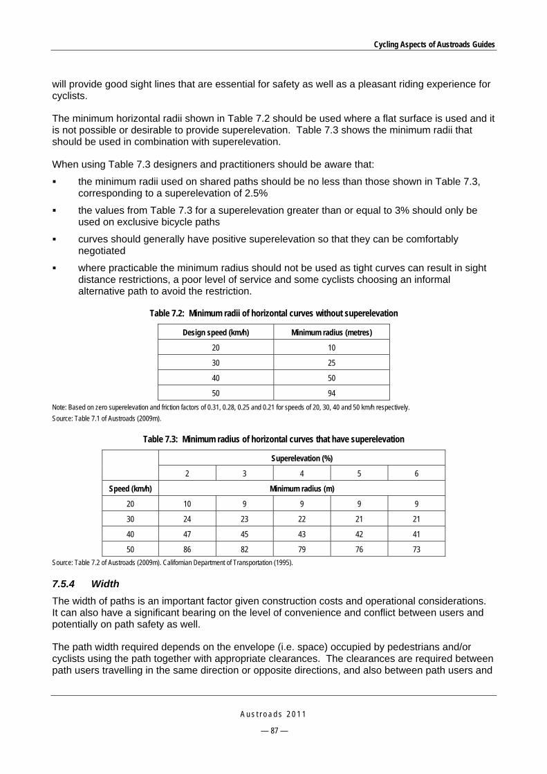
Cycling Aspects of Austroads Guides
A u s t r o a d s 2 0 1 1
— 87 —
will provide good sight lines that are essential for safety as well as a pleasant riding experience for cyclists.
The minimum horizontal radii shown in Table 7.2 should be used where a flat surface is used and it is not possible or desirable to provide superelevation. Table 7.3 shows the minimum radii that should be used in combination with superelevation.
When using Table 7.3 designers and practitioners should be aware that:
the minimum radii used on shared paths should be no less than those shown in Table 7.3, corresponding to a superelevation of 2.5%
the values from Table 7.3 for a superelevation greater than or equal to 3% should only be used on exclusive bicycle paths
curves should generally have positive superelevation so that they can be comfortably negotiated
where practicable the minimum radius should not be used as tight curves can result in sight distance restrictions, a poor level of service and some cyclists choosing an informal alternative path to avoid the restriction.
Table 7.2: Minimum radii of horizontal curves without superelevation
Design speed (km/h) Minimum radius (metres)
20 10
30 25
40 50
50 94
Note: Based on zero superelevation and friction factors of 0.31, 0.28, 0.25 and 0.21 for speeds of 20, 30, 40 and 50 km/h respectively.
Source: Table 7.1 of Austroads (2009m).
Table 7.3: Minimum radius of horizontal curves that have superelevation
Superelevation (%)
2 3 4 5 6
Speed (km/h) Minimum radius (m)
20 10 9 9 9 9
30 24 23 22 21 21
40 47 45 43 42 41
50 86 82 79 76 73
Source: Table 7.2 of Austroads (2009m). Californian Department of Transportation (1995).
7.5.4 Width
The width of paths is an important factor given construction costs and operational considerations. It can also have a significant bearing on the level of convenience and conflict between users and potentially on path safety as well.
The path width required depends on the envelope (i.e. space) occupied by pedestrians and/or cyclists using the path together with appropriate clearances. The clearances are required between path users travelling in the same direction or opposite directions, and also between path users and

Cycling Aspects of Austroads Guides
A u s t r o a d s 2 0 1 1
— 88 —
the edge of the path. Some allowance for the ability of cyclists to ride in a consistent wheel path (i.e. tracking of the bicycle within the envelope) is provided.
Bicycle paths
Table 7.4 shows desirable widths and acceptable ranges of width for bicycle paths (i.e. exclusive use). The upper limit of the acceptable range in the table should not discourage designers from providing a greater width where it is needed (e.g. very high demand that may also result in overtaking in both directions).
Table 7.4: Bicycle path widths
Path width (m)
Local access path Major path
Desirable minimum width 2.5 3.0
Minimum width – typical maximum 2.5(1) – 3.0 (2) 2.5(1) – 4.0(2)
1 A lesser width should only to be adopted where cyclist volumes and operational speeds will remain low. 2 A greater width may be required where the number of cyclists is very high.
Source: Figure 7.3 of Austroads (2009m).
Shared paths
Table 7.5 shows desirable widths and acceptable ranges of width for shared use paths. As for bicycle paths, the upper limit of the acceptable range in the table should not discourage designers from providing a greater width where it is needed (e.g. very high demand that may also result in overtaking in both directions).
Table 7.5: Shared path widths
Path width (m)
Local access path Commuter path Recreational path
Desirable minimum width 2.5 3.0 3.5
Minimum width – typical maximum 2.5(1) – 3.0(2) 2.5(1) – 4.0(2) 3.0(1) – 4.0(2)
1 A lesser width should only to be adopted where cyclist volumes and operational speeds will remain low. 2 A greater width may be required where the numbers of cyclists and pedestrians are very high or there is a high probability of conflict between users (e.g. people
walking dogs, roller bladers and skaters etc.).
Source: Figure 7.4 of Austroads (2009m).
Separated paths
Table 7.6 and Table 7.7 show desirable widths and acceptable ranges of width for two-way and one-way separated paths respectively. However, where it is appropriate (e.g. high traffic demand) designers may provide a greater width than the typical maximum shown in the tables.
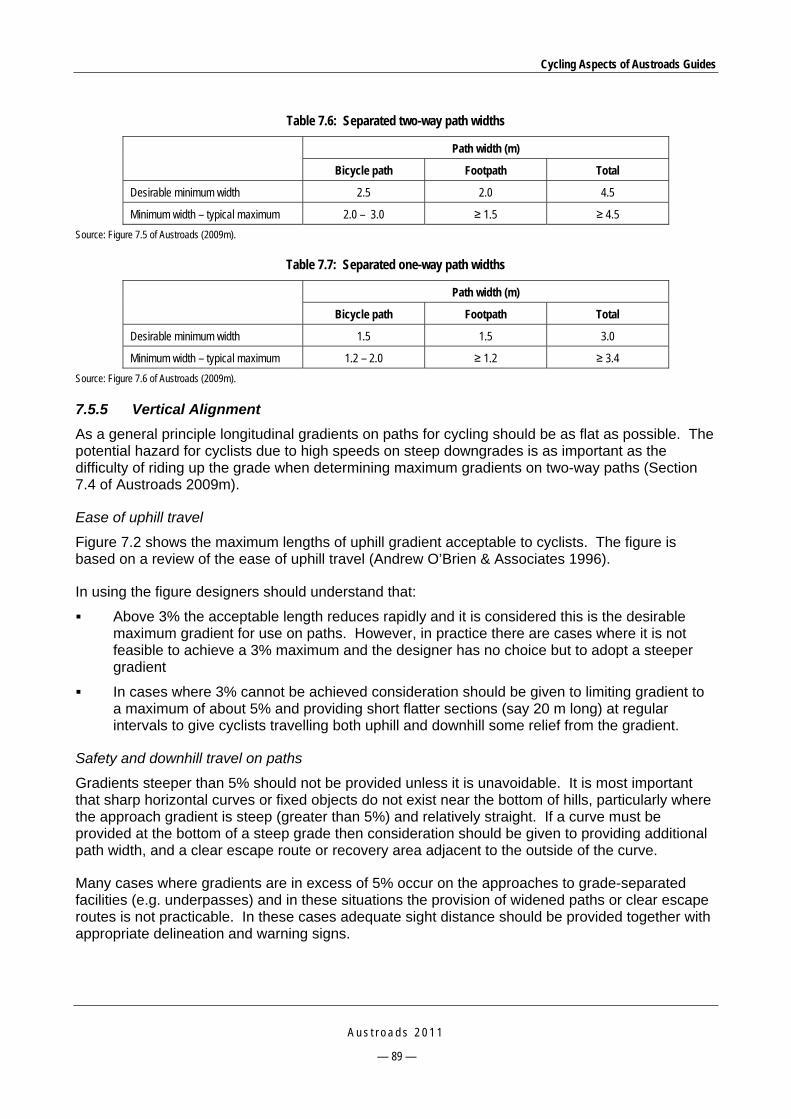
Cycling Aspects of Austroads Guides
A u s t r o a d s 2 0 1 1
— 89 —
Table 7.6: Separated two-way path widths
Path width (m)
Bicycle path Footpath Total
Desirable minimum width 2.5 2.0 4.5
Minimum width – typical maximum 2.0 – 3.0 ≥ 1.5 ≥ 4.5
Source: Figure 7.5 of Austroads (2009m).
Table 7.7: Separated one-way path widths
Path width (m)
Bicycle path Footpath Total
Desirable minimum width 1.5 1.5 3.0
Minimum width – typical maximum 1.2 – 2.0 ≥ 1.2 ≥ 3.4
Source: Figure 7.6 of Austroads (2009m).
7.5.5 Vertical Alignment
As a general principle longitudinal gradients on paths for cycling should be as flat as possible. The potential hazard for cyclists due to high speeds on steep downgrades is as important as the difficulty of riding up the grade when determining maximum gradients on two-way paths (Section 7.4 of Austroads 2009m).
Ease of uphill travel
Figure 7.2 shows the maximum lengths of uphill gradient acceptable to cyclists. The figure is based on a review of the ease of uphill travel (Andrew O’Brien & Associates 1996).
In using the figure designers should understand that:
Above 3% the acceptable length reduces rapidly and it is considered this is the desirable maximum gradient for use on paths. However, in practice there are cases where it is not feasible to achieve a 3% maximum and the designer has no choice but to adopt a steeper gradient
In cases where 3% cannot be achieved consideration should be given to limiting gradient to a maximum of about 5% and providing short flatter sections (say 20 m long) at regular intervals to give cyclists travelling both uphill and downhill some relief from the gradient.
Safety and downhill travel on paths
Gradients steeper than 5% should not be provided unless it is unavoidable. It is most important that sharp horizontal curves or fixed objects do not exist near the bottom of hills, particularly where the approach gradient is steep (greater than 5%) and relatively straight. If a curve must be provided at the bottom of a steep grade then consideration should be given to providing additional path width, and a clear escape route or recovery area adjacent to the outside of the curve.
Many cases where gradients are in excess of 5% occur on the approaches to grade-separated facilities (e.g. underpasses) and in these situations the provision of widened paths or clear escape routes is not practicable. In these cases adequate sight distance should be provided together with appropriate delineation and warning signs.

Cycling Aspects of Austroads Guides
A u s t r o a d s 2 0 1 1
— 90 —
Leng
th o
f gra
dien
t (m
)
Gradient (%)
Leng
th o
f gra
dien
t (m
)
Gradient (%)
Notes:
Gradients and the associated length would normally be based on the distance between the tangent points for an isolated steep section. However, where there are consecutive grades of varying steepness (all uphill) or large radius vertical curves, these should be calculated based on the intersection points of the respective vertical curves.
In general, the ‘acceptable’ line in the figure would be satisfactory for paths with a high proportion of regular or physically fit cyclists, which in most instances would include commuter and sporting cyclists. Otherwise, the ‘desirable’ line in the figure is recommended.
Source: Figure 7.1 of Austroads (2009m). Based on a review by Andrew O’Brien & Associates (1996).
Figure 7.2: Desirable uphill gradients for ease of cycling
7.5.6 Crossfall and Drainage
Crossfall
Water ponding on paths has a significant impact on the level of service provided to cyclists as spray leads to grit on both bicycle and rider. On straight sections crowning of the pavement is preferable as it results in less accumulation of debris. On sealed surfaces a crossfall of 2% – 4% should be adequate to effectively dispose of surface water whereas unsealed surfaces may require 5% to prevent puddles of water from developing.
Where paths are for shared use, the needs of other path users (e.g. impaired pedestrians) should be considered. In particular, AS/NZS 1428.4.1:2009 specifies that a path crossfall should not exceed 2.5% (1 in 40) to cater for people who have a disability.
Drainage
Paths for cycling should be constructed so that water does not pond on the surface and debris does not wash onto the path during heavy rain. The path should therefore have adequate crossfall
Cycling Aspects of Austroads Guides
A u s t r o a d s 2 0 1 1
— 91 —
and catch drains to collect water and prevent water and litter from flowing onto the path. Typical path cross-sections are illustrated in Figure 7.3 of Austroads (2009m).
Major commuting and recreational paths should be designed for an equivalent flood immunity as that adopted for local roads unless suitable safe alternative routes can be easily accessed from the path. Major recreational paths that follow watercourses will have to satisfy the requirements of the responsible authority.
Further guidance on crossfall and drainage for paths is provided in Section 7.6 of Austroads (2009m).
7.5.7 Clearances, Batters and Fences
Clearances
It is important for safe operation that adequate clearance is provided between bicycle operating spaces for cyclists traveling in opposite directions and between the cyclist operating spaces and potential hazards beside paths (e.g. fixed objects, vertical drops, steep batters).
The clearance between cyclist operating spaces varies according to the type of use and operating speeds as follows:
On paths designed for commuting and major recreational activity a minimum lateral clearance of 1.0 m is required between opposing bicycle operating spaces because of the high relative speed which exists when cyclists approach one another from opposite directions at speeds of 30 km/h or more (i.e. closing speed of 60 km/h).
On recreational paths where the speeds of cyclists are not likely to exceed 20 km/h a minimum lateral clearance of 0.4 m is necessary between opposing bicycle operating spaces.
The following guidelines should be applied for clearances between the cyclist operating spaces and potential hazards beside paths:
Where both the areas beside the path and the path alignment are both relatively flat a lateral clearance of at least 1.0 m (0.5 m absolute minimum) should be provided between the edge of any path for cycling and any obstacle, which if struck may result in cyclists losing control or being injured. However, on high-speed paths it is most desirable to have a clearance considerably greater than 1.0 m.
Where it is considered that a hazard beside the path has attributes that could cause serious injury to cyclists (e.g. sharp surfaces such as the rear side of the posts and rails of steel W-beam road safety barrier), designers should assess the risk of cyclists losing control on the particular section of path, and consider either increasing the lateral clearance or shielding cyclists from the hazard. Depending on the situation a rub rail behind the posts or a cyclist fence near the edge of the path could be provided.
Where a vertical drop or a steep batter exists or must be provided adjacent to the path the guidance under Batters and fences (below) should be applied.

Cycling Aspects of Austroads Guides
A u s t r o a d s 2 0 1 1
— 92 —
Batters and fences
The installation of a fence at the side of a path used by cyclists is desirable where:
there is a steep batter or large vertical drop located in close proximity to the path
the path is adjacent to an arterial road and it is necessary to restrict cyclist access to the road
a bridge or culvert exists on a path
a hazard exists adjacent to a particular bicycle facility
cyclists are likely to be ‘blazing a separate trail’ at an intersection between paths or around a path terminal.
Reference should be made Section 7.3.6 of Austroads (2009m) for further guidance and examples of fences. Figure 7.4 of that document provides a specific recommendation for the provision of a fence on a path in close proximity to a steep batter or vertical drop.
Further guidance on clearances, batters and fences is provided in Section 7.7 of Austroads (2009m).
7.5.8 Sight Distance
Sight distance is covered in Section 7.8 of Austroads (2009m). For safe travel cyclists must be able to see across the inside of horizontal curves, under overhead obstructions in sag curves (e.g. where a path passes under a road) and over vertical crest curves a sufficient distance to enable them to stop or take evasive action if necessary in order to avoid another cyclist, a pedestrian or an obstacle in their path.
Figure 7.3 shows the stopping sight distances that should be provided to enable a cyclist to stop for various combinations of bicycle operating speeds and gradients.
It is essential that aall two-way bicycle paths should be designed to provide a sight distance between opposing cyclists (i.e. as shown across a horizontal curve in Figure 7.4) at least equivalent to twice the stopping sight distance given by Figure 7.3. This is to ensure that cyclists who are overtaking can avoid a head-on collision.

Cycling Aspects of Austroads Guides
A u s t r o a d s 2 0 1 1
— 93 —
Minimum stopping sight distance (metres)
Gra
dien
t (%
)
Minimum stopping sight distance (metres)
Gra
dien
t (%
)
Source: Figure 7.7 of Austroads (2009m). AASHTO (1991).
Figure 7.3: Minimum stopping sight distance for cyclists
Path sight distances can be drastically reduced by the growth of vegetation and hence the location and maintenance of vegetation are critical to safe path operation. Figure 7.4 illustrates the relationship between stopping sight distance, radius of the curve and the lateral clearance to significant visibility obstructions such as extensive vegetation or an earth embankment. Isolated features including trees do not necessarily constitute a significant obstruction if cyclists can see most of the curve beyond them.

Cycling Aspects of Austroads Guides
A u s t r o a d s 2 0 1 1
— 94 —
Stopping sight distance (metres)
Late
ral c
lear
ance
M, (
met
res)
Note: Line of sight is 600 mm above centre line of inside lane, at point of obstruction
Stopping sight distance (metres)
Late
ral c
lear
ance
M, (
met
res)
Note: Line of sight is 600 mm above centre line of inside lane, at point of obstruction
Source: Figure 7.8 of Austroads (2009m). Californian Department of Transportation (1995).
Figure 7.4: Lateral clearances on horizontal curves
A vertical curve should join all changes of grade. Crest vertical curves must be of sufficient length to give the cyclist the stopping sight distance shown in Figure 7.3. Where practicable, sag curves should be the same length as equivalent crest curves to ensure comfort and an aesthetically pleasing path alignment. Figure 7.5 shows the minimum length of vertical curves for various changes of gradient and design speeds.

Cycling Aspects of Austroads Guides
A u s t r o a d s 2 0 1 1
— 95 —
Minimum length of vertical curve (metres)
Alg
ebra
ic c
hang
e in
gra
de (%
)
Minimum length of vertical curve (metres)
Alg
ebra
ic c
hang
e in
gra
de (%
)
Source: Figure 7.8 of Austroads (2009m). Californian Department of Transportation (1995).
Figure 7.5: Minimum length of crest vertical curves
7.6 Path Crossings of Roads 7.6.1 General
This section discusses unsignalised cyclist crossing treatments of roads for situations where cyclists either have to yield to motor vehicles or have priority over motor vehicles.
Unsignalised crossings of two-lane two-way local streets or collector roads may require cyclists to give way to road traffic, and in low volume streets (< 3000 vpd) need not provide a refuge for cyclists in the middle of the road. In such situations the treatment provides for a straight crossing of the road using kerb ramps on both sides of the road with a suitable terminal treatment. A refuge in the centre of the road is desirable on busy roads (e.g. > 3000 vpd) so that cyclists can stage their crossing. Where important cycling routes intersect with low volume local roads it may be desirable for cyclists to have priority over motor traffic.
One or more of the following facilities can assist cyclists in crossing roads:
grade separation
a signalised crossing with bicycle detection and lights
median refuge
road narrowing of excessively wide roads whilst also providing for cyclist needs along the road
on-road lanes or off-road path connections to nearby traffic signals, to be supplemented with bicycle detection and lanterns
a crossing that gives priority for cyclists in accordance with road rules.

Cycling Aspects of Austroads Guides
A u s t r o a d s 2 0 1 1
— 96 —
7.6.2 Bicycle Path Crossing
Figure 7.6 shows a treatment of a bicycle path where it intersects a low-volume street. This example includes separated paths in the verges of the street. Whilst separated paths are shown the treatment can be applied where footpaths or shared paths are provided within the street. Space is often not available to provide separated paths for pedestrians and cyclists within the verge of a road. However, the arrangement illustrates that it is particularly important to clearly define the priority that applies in order to reduce the likelihood of conflict between cyclists and pedestrians at the intersection between paths.

Cycling Aspects of Austroads Guides
A u s t r o a d s 2 0 1 1
— 97 —
Source: Figure 9.1 of Austroads (2009h). Adapted from RTA (2005).
Figure 7.6: Bicycle path crossing of a two-way two-lane road and separated paths

Cycling Aspects of Austroads Guides
A u s t r o a d s 2 0 1 1
— 98 —
7.6.3 Refuges for Path Crossings away from Intersections
Where an off-road path crosses a busy local street or an arterial road away from an intersection it may be necessary to provide facilities to aid the cyclists to make a safe crossing. These facilities may be in the form of controlled crossings as discussed previously, or physical refuges. Physical refuges in the centre of the road are recommended to enable a staged crossing where volumes are greater than 3000 vpd. A typical refuge is shown in Figure 7.7 for a path crossing a two-way, four-lane road. Separate areas may be provided within the refuge for cyclists and pedestrians if sufficient space can be made available. Whilst the figure shows a shared path the treatment can be used for bicycle-only crossings.
Notes:
Where required, tactile ground surface indicators should be provided on paths and ramps in accordance with AS/NZS 1428.4.1: 2009 and jurisdictional guidelines.
This figure is identical to Figure 9.2 of Austroads (2009h) except that an error has been corrected in the definition of dimension ‘Z’.
Source: Based on AS 1742.10: 1990.
Figure 7.7: Example of a cyclist and pedestrian refuge at a mid-block location
In order to accommodate a bicycle which is typically 1.75 m long, it is desirable that a refuge be at least 2.0 m wide. However, 1.8 m may suffice in tight situations. Where there are concentrated cyclist demands at certain periods of the day (e.g. secondary schools) a wider and longer storage area may be required within the refuge to provide additional space and separate areas for cyclists and pedestrians.
Refuges can be furnished with a holding rail to allow a stationary cyclist to remain mounted within the refuge area. Rails should be located clear of the gap although where the gap is wide (i.e. greater than 2.0 m) the rails can be located within the gap, on the left-hand side. Refuges should also be provided with adequate street lighting to enhance visibility of the island and cyclists using it at night.
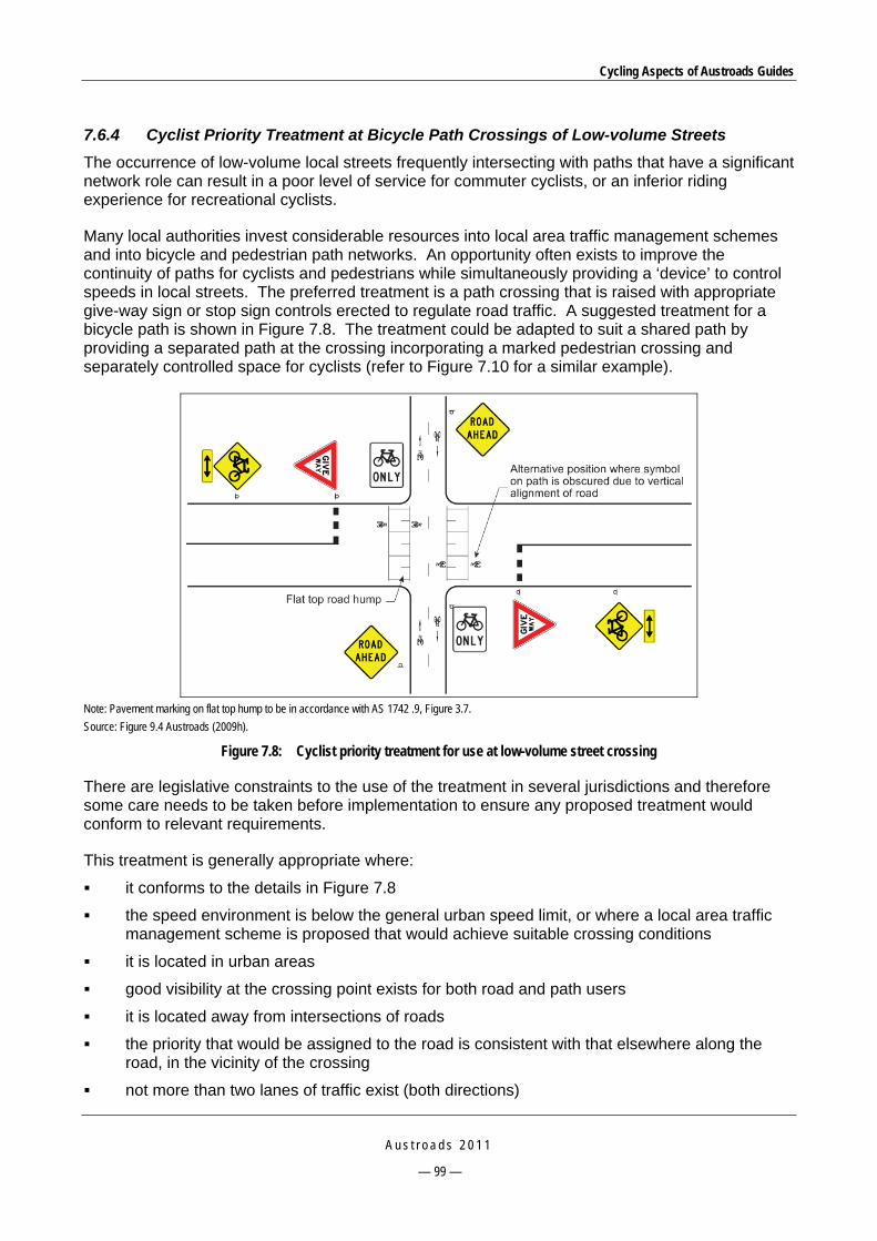
Cycling Aspects of Austroads Guides
A u s t r o a d s 2 0 1 1
— 99 —
7.6.4 Cyclist Priority Treatment at Bicycle Path Crossings of Low-volume Streets
The occurrence of low-volume local streets frequently intersecting with paths that have a significant network role can result in a poor level of service for commuter cyclists, or an inferior riding experience for recreational cyclists.
Many local authorities invest considerable resources into local area traffic management schemes and into bicycle and pedestrian path networks. An opportunity often exists to improve the continuity of paths for cyclists and pedestrians while simultaneously providing a ‘device’ to control speeds in local streets. The preferred treatment is a path crossing that is raised with appropriate give-way sign or stop sign controls erected to regulate road traffic. A suggested treatment for a bicycle path is shown in Figure 7.8. The treatment could be adapted to suit a shared path by providing a separated path at the crossing incorporating a marked pedestrian crossing and separately controlled space for cyclists (refer to Figure 7.10 for a similar example).
Note: Pavement marking on flat top hump to be in accordance with AS 1742 .9, Figure 3.7.
Source: Figure 9.4 Austroads (2009h).
Figure 7.8: Cyclist priority treatment for use at low-volume street crossing
There are legislative constraints to the use of the treatment in several jurisdictions and therefore some care needs to be taken before implementation to ensure any proposed treatment would conform to relevant requirements.
This treatment is generally appropriate where:
it conforms to the details in Figure 7.8
the speed environment is below the general urban speed limit, or where a local area traffic management scheme is proposed that would achieve suitable crossing conditions
it is located in urban areas
good visibility at the crossing point exists for both road and path users
it is located away from intersections of roads
the priority that would be assigned to the road is consistent with that elsewhere along the road, in the vicinity of the crossing
not more than two lanes of traffic exist (both directions)
Cycling Aspects of Austroads Guides
A u s t r o a d s 2 0 1 1
— 100 —
the proportion of commercial traffic is low
a warrant for a higher form of road crossing is not satisfied, such as a pedestrian actuated signal crossing, which should then be used as an alternative (AS 1742.10: 1990 or relevant state regulations).
7.6.5 Path Crossings of Side Roads
Paths which run parallel to busy roads often have to cross side roads which may be minor or important traffic routes and the intersection may be signalised or unsignalised. These crossings are covered in Section 9.6 of the Guide to Road Design – Part 4: Intersections and Crossings – General (Austroads 2009h).
Where a bicycle path or shared path is provided in the verge of a road, cyclists using the path will often have to cross intersecting side streets. These side street crossings should be designed:
to ensure that motorists are aware of the existence of the crossing and the priority that applies
so that the location and design of the crossing, and the priority adopted, does not put motorists at risk when turning from the major road
to encourage safe and correct use by cyclists.
Where the path is located on one side of a road, kerb ramps should be provided opposite every side street to enable access for local users.
7.6.6 Path Approach Design Criteria
The key requirements for the intersection between a path in a road reservation and a side road (Section 9.6.2 of Austroads 2009h) are:
approach sight distance should be provided for drivers approaching the intersection from the side road
drivers turning from the major road into the side street should have clear sight lines to cyclists using the path in both directions
the speeds of cyclists using the path should be controlled on the path approaches to the intersection.
Sharp downgrades on path approaches to road crossings should be avoided where possible. Where the path alignment is straight on the approach to a road then the path should be as flat as possible. It is desirable that the longitudinal downgrade should be limited to 3% and should not exceed 5%.
Paths for cycling should be aligned to intersect roads at approximately 90°. Where the approach sight distance for cyclists is restricted, appropriate warning signs should be provided or measures taken to reduce the approach speed of cyclists.
7.6.7 Types of Crossings of Side Roads
There are three types of treatment available for the design of path crossings of side streets, a design where the path approach is bent-out (i.e. is deviated away from the major road), a design where the approach is straight, and a treatment where a one-way bicycle path is deviated to become an on-road bicycle lane. These crossings are also covered in Section 9.6.3 of Austroads (2009h). The first two types of treatment may be applied to bicycle paths or separated paths.
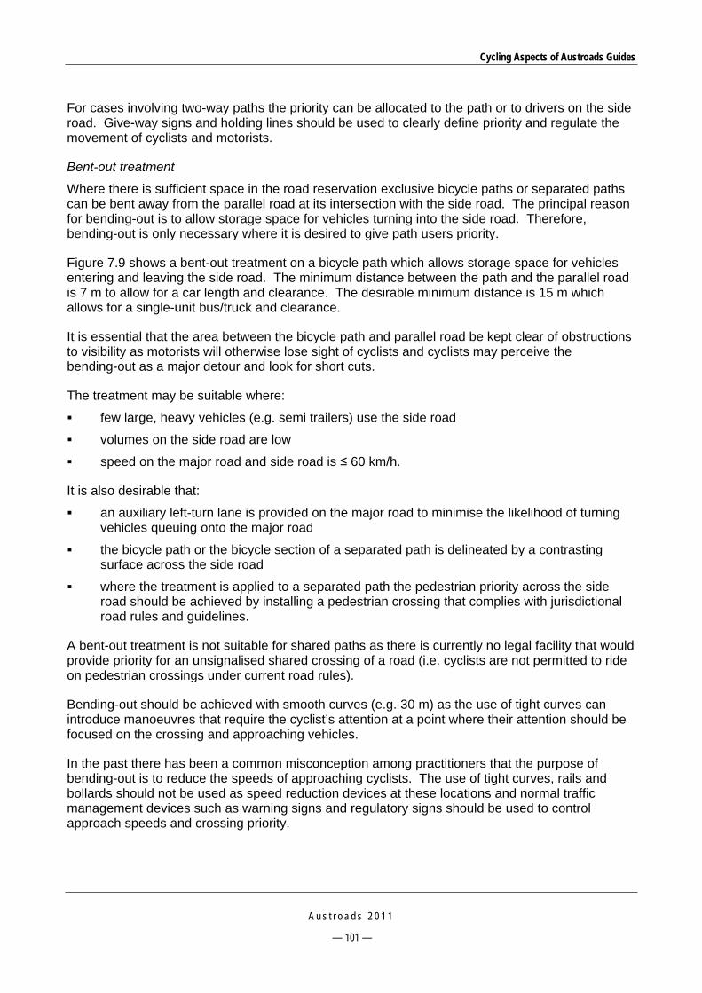
Cycling Aspects of Austroads Guides
A u s t r o a d s 2 0 1 1
— 101 —
For cases involving two-way paths the priority can be allocated to the path or to drivers on the side road. Give-way signs and holding lines should be used to clearly define priority and regulate the movement of cyclists and motorists.
Bent-out treatment
Where there is sufficient space in the road reservation exclusive bicycle paths or separated paths can be bent away from the parallel road at its intersection with the side road. The principal reason for bending-out is to allow storage space for vehicles turning into the side road. Therefore, bending-out is only necessary where it is desired to give path users priority.
Figure 7.9 shows a bent-out treatment on a bicycle path which allows storage space for vehicles entering and leaving the side road. The minimum distance between the path and the parallel road is 7 m to allow for a car length and clearance. The desirable minimum distance is 15 m which allows for a single-unit bus/truck and clearance.
It is essential that the area between the bicycle path and parallel road be kept clear of obstructions to visibility as motorists will otherwise lose sight of cyclists and cyclists may perceive the bending-out as a major detour and look for short cuts.
The treatment may be suitable where:
few large, heavy vehicles (e.g. semi trailers) use the side road
volumes on the side road are low
speed on the major road and side road is ≤ 60 km/h.
It is also desirable that:
an auxiliary left-turn lane is provided on the major road to minimise the likelihood of turning vehicles queuing onto the major road
the bicycle path or the bicycle section of a separated path is delineated by a contrasting surface across the side road
where the treatment is applied to a separated path the pedestrian priority across the side road should be achieved by installing a pedestrian crossing that complies with jurisdictional road rules and guidelines.
A bent-out treatment is not suitable for shared paths as there is currently no legal facility that would provide priority for an unsignalised shared crossing of a road (i.e. cyclists are not permitted to ride on pedestrian crossings under current road rules).
Bending-out should be achieved with smooth curves (e.g. 30 m) as the use of tight curves can introduce manoeuvres that require the cyclist’s attention at a point where their attention should be focused on the crossing and approaching vehicles.
In the past there has been a common misconception among practitioners that the purpose of bending-out is to reduce the speeds of approaching cyclists. The use of tight curves, rails and bollards should not be used as speed reduction devices at these locations and normal traffic management devices such as warning signs and regulatory signs should be used to control approach speeds and crossing priority.

Cycling Aspects of Austroads Guides
A u s t r o a d s 2 0 1 1
— 102 —
Source: Figure 9.9 of Austroads 2009h. Based on RTA (2005).
Figure 7.9: Bicycle path crossing bent-out at side road
Straight crossings (not bent-out)
Figure 7.10 shows an option for a straight crossing on a separated two-way bicycle path. The treatment provides for both cyclists and pedestrians to have formal crossings of the side street

Cycling Aspects of Austroads Guides
A u s t r o a d s 2 0 1 1
— 103 —
controlled by pedestrian crossing signs and give-way signs respectively. To maintain better route continuity and rider comfort this treatment may be placed on a platform as shown in the figure.
The treatment is suitable where traffic volumes in side streets are low (e.g. residential streets). Where side streets have higher volumes a bent-in treatment may be appropriate. In instances where pedestrian and cyclist volumes are relatively low, priority will often be given to motor vehicles.
The main benefit of a straight crossing relatively close to the major road is that the path has a higher visibility for road users where space for a bent-out crossing is not available. It is important therefore that the path is placed close enough to the edge of the major road to maintain visibility although at least 6 m should be provided between the treatment and the major road in order to store a car clear of the crossing. This separation also enables a left-turn auxiliary lane to be provided.
Source: Figure 9.10 of Austroads (2009h). Based on RTA (2005).
Figure 7.10: Bicycle path crossing (not bent-out at side road)
Cycling Aspects of Austroads Guides
A u s t r o a d s 2 0 1 1
— 104 —
Bent-in treatment
This treatment provides for a one-way bicycle path to transition into an on-road bicycle lane, thereby enabling cyclists to have priority across the side street. It should not be used for two-way paths because of the head-on conflict that would arise between cyclists and motor vehicles. This treatment is shown in Figure 7.11.
The bent-in treatment has the advantage of providing greater visibility of cyclists for drivers at the intersection and should enable drivers to better anticipate the movement of cyclists. It also easily provides for cyclist priority at the intersection and for the transition from path to on-road lane to be physically protected. These treatments are suitable only for experienced cyclists who have the skill and maturity to safely enter and ride in traffic. They are not suitable for paths used by children riding to schools.
If a pedestrian crossing is provided in the side street it should be located at least a vehicle storage length from the side-street holding line.

Cycling Aspects of Austroads Guides
A u s t r o a d s 2 0 1 1
— 105 —
Source: Figure 9.11 of Austroads (2009h). Based on RTA (2005).
Figure 7.11: One-way bicycle path crossing (bent-in side road)

Cycling Aspects of Austroads Guides
A u s t r o a d s 2 0 1 1
— 106 —
7.7 Intersections of Paths with Paths Intersections between bicycle paths and shared paths are relatively simple arrangements. Practitioners should refer to Section 9.3 of Austroads (2009m) for detailed guidance. In general, the intersections of paths should be constructed and controlled in accordance with the established principles of codes of practice for roads. For example:
the controls and layout should favour the predominant flow on the major through route and meet geometric requirements such as sight distance and gradients
crossing and entering speeds and angles for bicycles moving from one path to another should be controlled through the geometry.
7.8 Path Terminal Treatments A path terminal treatment may be required where a shared path or bicycle path intersects with a road and applies to recreational and commuter paths that cross a road from a reservation, or to paths that follow a major road and cross side streets. Guidance on the use and design of path terminal treatments is provided in Section 10 of Austroads (2009m).
Path terminal treatments for off-road, shared-user paths and bicycle paths are generally provided to:
restrict illegal access by drivers of motor vehicles to road reserves and parkland to prevent damage to paths and other assets and prevent rubbish from being dumped illegally
advise cyclists that there is a road ahead and slow cyclists down before they cross the road.
The objective of a path terminal treatment is to prevent illegal vehicle access with a design and/or device that maintains a safe operating environment for cyclists. Austroads (2009m) provides examples and guidelines for the design of the treatments that include separation of entry and exit, bollards or staggered fences (refer to Figure 7.12, Figure 7.13 and Figure 7.14).

Cycling Aspects of Austroads Guides
A u s t r o a d s 2 0 1 1
— 107 —
RampKerb
Road
1.4 m 1.4 m
Off-road path
Unbroken/tactile line where path deviates at terminals
Landscaping etc. suitable to prevent entry by motor traffic
Holding rail
5 m
Fence line
RampKerb
Road
1.4 m 1.4 m
Off-road path
Unbroken/tactile line where path deviates at terminals
Landscaping etc. suitable to prevent entry by motor traffic
Holding rail
5 m
Fence line
RampKerb
Road
1.4 m 1.4 m
Off-road path
Unbroken/tactile line where path deviates at terminals
Landscaping etc. suitable to prevent entry by motor traffic
Holding rail
5 m
Fence line
Source: Figure 10.1 of Austroads (2009m). Based on VicRoads (2005).
Figure 7.12: Separate entry and exit terminal
Source: Figure 10.3 of Austroads (2009m). RTA (2005).
Figure 7.13: Example of a bollard treatment
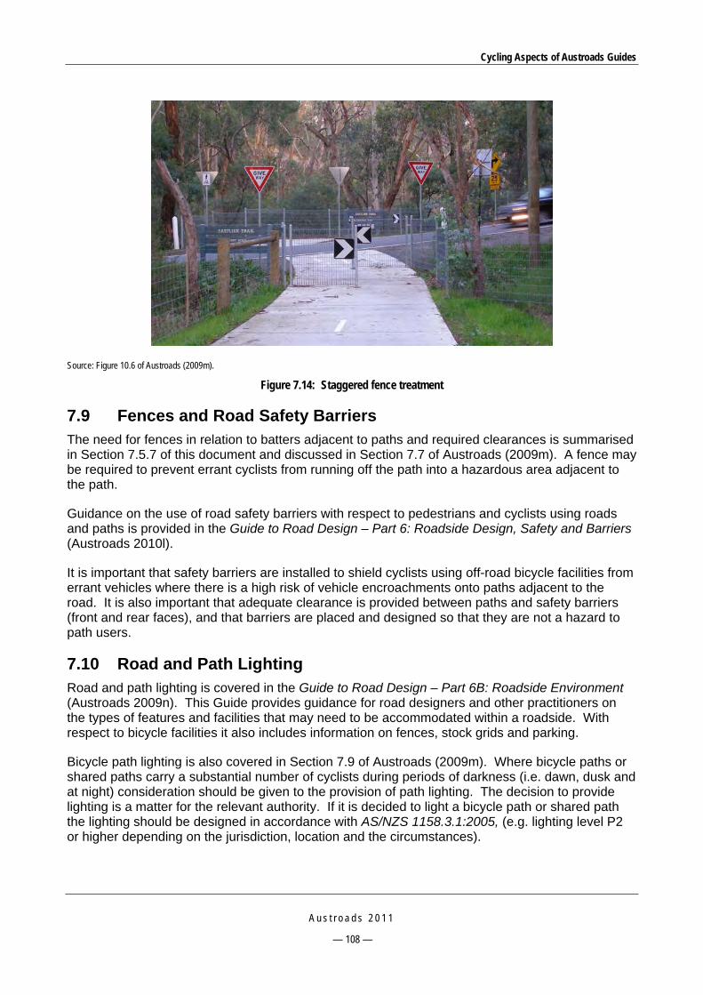
Cycling Aspects of Austroads Guides
A u s t r o a d s 2 0 1 1
— 108 —
Source: Figure 10.6 of Austroads (2009m).
Figure 7.14: Staggered fence treatment
7.9 Fences and Road Safety Barriers The need for fences in relation to batters adjacent to paths and required clearances is summarised in Section 7.5.7 of this document and discussed in Section 7.7 of Austroads (2009m). A fence may be required to prevent errant cyclists from running off the path into a hazardous area adjacent to the path.
Guidance on the use of road safety barriers with respect to pedestrians and cyclists using roads and paths is provided in the Guide to Road Design – Part 6: Roadside Design, Safety and Barriers (Austroads 2010l).
It is important that safety barriers are installed to shield cyclists using off-road bicycle facilities from errant vehicles where there is a high risk of vehicle encroachments onto paths adjacent to the road. It is also important that adequate clearance is provided between paths and safety barriers (front and rear faces), and that barriers are placed and designed so that they are not a hazard to path users.
7.10 Road and Path Lighting Road and path lighting is covered in the Guide to Road Design – Part 6B: Roadside Environment (Austroads 2009n). This Guide provides guidance for road designers and other practitioners on the types of features and facilities that may need to be accommodated within a roadside. With respect to bicycle facilities it also includes information on fences, stock grids and parking.
Bicycle path lighting is also covered in Section 7.9 of Austroads (2009m). Where bicycle paths or shared paths carry a substantial number of cyclists during periods of darkness (i.e. dawn, dusk and at night) consideration should be given to the provision of path lighting. The decision to provide lighting is a matter for the relevant authority. If it is decided to light a bicycle path or shared path the lighting should be designed in accordance with AS/NZS 1158.3.1:2005, (e.g. lighting level P2 or higher depending on the jurisdiction, location and the circumstances).

Cycling Aspects of Austroads Guides
A u s t r o a d s 2 0 1 1
— 109 —
8 PROVISON AT STRUCTURES The design of structures is very important to cyclists. Existing road bridges are often narrower than the road on the approaches thus creating a squeeze point for cyclists. Because of the high relative cost of new bridges there is an understandable tendency for designers to be as economical as possible in the widths provided for the various users. It is important, however, that road managers look for ways to better cater for cyclists at all existing structures and that designers and planners ensure that cyclists are adequately provided for in the design of all new structures.
Guidance on the provision of facilities for cyclists at structures is covered in Section 11 of the Guide to Road Design – Part 6A: Pedestrian and Cyclist Paths (Austroads 2009m).
The structures may cross rivers, railway lines or busy roads. They may be overpasses or underpasses that cater for motor traffic, small bridges or underpasses specifically for cyclists and pedestrians, large drainage culverts which also accommodate cyclists or a bicycle structure attached to a road bridge.
The primary requirements of cyclists using bridges and underpasses are that designers should provide:
adequate path width and/or bicycle lane width and horizontal clearances to objects (e.g. walls, safety barriers, kerbs, fences, poles, street furniture etc.)
adequate vertical clearance, particularly in underpasses
good sight lines into and through structures
a smooth surface that is not slippery under any conditions including the surface of expansion joints
adequate turning radii at changes of direction on pedestrian/cyclist overpasses and underpasses
adequate drainage infrastructure, particularly at each end of underpasses.
Provision for cyclists in long road tunnels is problematic because of the very high cost of providing space within major tunnels, particularly treatments that provide a safe and healthy cycling environment. Nevertheless, the needs of cyclists should be considered as part of the planning and design of tunnels and if a satisfactory facility cannot be provided within the tunnel the availability or provision of a suitable alternative route should be investigated.

Cycling Aspects of Austroads Guides
A u s t r o a d s 2 0 1 1
— 110 —
9 TRAFFIC CONTROL DEVICES
9.1 Signs Signing of bicycle facilities provides the information to assist all road users to move safely and conveniently on the road and bicycle network. The three main categories of signs and their functions are:
regulatory signs – regulate and advise the type of facility within the context of the overall road system, e.g. whether a facility is shared with pedestrians or for the exclusive use of cyclists
warning signs – warn users of identifiable potential hazards within the riding environment
guide signs – guide users around the network.
Bicycle routes should be signposted to indicate destinations and, if required, the distance to them. Uniformity of design and application of signs is desirable to avoid confusion and potential hazardous situations, applicable particularly for bicyclists travelling away from their local area. The Guide to Traffic Management – Part 10: Traffic Control and Communication Devices (Austroads 2009e) provides guidance on signs, markings and signals for bicycles. Practitioners should also refer to AS 1742.2: 2009 which provides information on general signage and AS 1742.9: 2000 as it provides details of facilities including signage specifically for bicycles.
9.2 Pavement Markings In addition to signs, the safety and effectiveness of bicycle facilities is dependent on the provision of appropriate and high-quality delineation including pavement markings.
Pavement markings are necessary for all on-road facilities and also for major bicycle paths, shared paths and separated paths.
9.2.1 Roads
Bicycle lanes are generally separated from general traffic by a 100 mm wide continuous white line. In areas where bicycles and motor vehicles cross or intersect, continuity lines are used to define the bicycle lane. Figure 9.1 provides an illustration of a bicycle lane treatment for a road that shows the marking treatment through an unsignalised intersection, on the approach to a signalised intersection including a ‘head-start’ treatment, and adjacent to angle parking.

Cycling Aspects of Austroads Guides
A u s t r o a d s 2 0 1 1
— 111 —
Source: Figure 6.5 of Austroads (2009e). VicRoads (2001).
Figure 9.1: Example of bicycle lane markings
9.2.2 Paths
Separation lines on shared paths and bicycle paths should be marked in accordance with AS 1742.9:2000.
9.3 Pavement Surface Colour Green coloured pavement surfaces may be used to enhance the delineation of areas of pavement that are used for bicycle lanes. The recommended Australian Standard colour for bicycle facility surfacing is Emerald Green G13 (refer to Section 6.6 of the Guide to Traffic Management – Part 10: Traffic Control and Communication Devices, Austroads 2009e).
The surfacing is relatively expensive, and guidelines for its use vary among jurisdictions. Some road authorities are choosing to provide coloured surfacing throughout the entire area of some bicycle lanes in order to provide enhanced recognition by motorists and to improve compliance.
The use of green surfacing for bicycle lanes by some authorities may be limited to areas where cyclists experience considerable stress, such as:
areas where the paths of motor vehicles and bicycles cross or weave, typically on the approaches and departures of intersections at the tapers to left-turn lanes and added lanes (diverge and merge areas)
within particularly complex intersections, or very wide intersections, where enhanced delineation of the bicycle lane is essential.

Cycling Aspects of Austroads Guides
A u s t r o a d s 2 0 1 1
— 112 —
9.4 Bicycle Crossing Lights 9.4.1 Bicycle Aspects
Bicycle aspects are discussed in Section 8.1.4 of Austroads (2009e) and Section E6, Appendix E of the Guide to Traffic Management – Part 9: Traffic Operations (Austroads 2009d).
Where regulations permit, bicycle aspects can be used in a similar way to pedestrian aspects to control cyclists crossing the road, or in a similar way to vehicle aspects to control on-road cyclists at an intersection. The symbol for bicycle aspects is shown in Figure 9.2.
Source: Figure 8.1 of Austroads (2009e).
Figure 9.2: Bicycle signal aspect
Two aspects, red and green, are used for road crossings (except in New Zealand). Three aspects – red, yellow and green – are used at road intersections with exclusive bicycle lanes, or at intersections of a road and exclusive bicycle path. Under the Australian Road Rules traffic signals relating to cycling movements are called bicycle crossing lights.
Two-aspect bicycle crossing lights used at mid-block signalised crossings or intersection signalised crossings are connected to the same signal group in the controller that drives the two-aspect pedestrian signal faces. In this case, the pedestrian ‘walk’ and ‘clearance’ times apply to the bicycles as well.
Three-aspect bicycle crossing lights can also be used at signalised intersections. In this case:
For bicycle movements parallel with a main road and crossing narrow minor roads, the bicycle crossing lights are connected to the adjacent vehicle signal group, and introduced with the green display for vehicles and terminated with the vehicle movement.
For bicycle movements across a main road, and for those parallel with a main road and crossing wide minor roads, the bicycle crossing lights are driven by a separate signal group with green, yellow and red times that reflect a bicycle speed of 20 km/h.
The following measures can be adopted in order to allow for slower speeds of cyclists compared with vehicle speeds:
Adjusting the yellow time for the bicycle movement to warn cyclists to stop before other traffic in the same phase, i.e. increase the intergreen time only for the cyclists (effectively providing an early cut-off). Since this reduces the bicycle green time, it should be ensured that the combined green plus intergreen time is sufficient for a cyclist accelerating from rest at the stop line to clear the controlled area.

Cycling Aspects of Austroads Guides
A u s t r o a d s 2 0 1 1
— 113 —
Allowing the cyclists to move off before the vehicle traffic (late start). This is appropriate where the bicycle lane does not continue through the intersection and bicycles have to merge with other traffic.
It is recommended that, at intersections, a stop line for bicycles is placed 2 m downstream of the normal stop line so that left-turning motor vehicle drivers, in particular bus and truck drivers, will be aware of bicycles waiting for a green signal. If vehicles cannot turn left, there is no need for this treatment.
9.4.2 Bicycle Detection
Bicycle detection at signals is covered in Section 7.1.7 of Austroads (2009d).
When separate bicycle lanes are provided and bicycle detection is required, loop detectors with very sensitive loop arrangements spanning the whole width of the bicycle lane are necessary.
Where bicycle traffic shares lanes with other vehicles, it is not always possible to detect bicycles due to their small electromagnetic footprint. It might be appropriate in such cases to install other devices such as push buttons to assist bicycle riders to lodge a demand, or pavement markings to indicate the most bicycle-sensitive area of the detection zone or, where bicycle volumes are low, do nothing.

Cycling Aspects of Austroads Guides
A u s t r o a d s 2 0 1 1
— 114 —
10 CONSTRUCTION AND MAINTENANCE
10.1 General If bicycle paths or on-road facilities are not adequately constructed and maintained, cyclists are not likely to use them, or may swerve in order to avoid surface irregularities thus creating a hazardous situation. The importance of maintenance in relation to cyclist safety is referred to throughout the Guide to Road Design – Part 6A: Pedestrian and Cyclist Paths (Austroads 2009m) and Section 12 and Appendix B of that Guide provide information on construction and maintenance considerations.
Smooth, debris-free surfaces are a fundamental requirement for riding bicycles in safety on paths and roads. As cyclists ride at speeds up to 50 km/h on downhill grades, a rough surface or pothole can cause a cyclist to fall, leave the path or road and crash or come into conflict with other path or road users. On uphill grades on roads, the speed differential between cyclists and motor traffic is greater and hence cyclists are exposed to potential conflict with motor traffic for a relatively long time as they manoeuvre around poor surfacing.
Most bicycles have no suspension or shock absorbers and many bicycles have relatively thin tyres inflated to high pressures. Consequently, when a cyclist hits a pothole at speed it is uncomfortable, difficult to maintain control and potentially hazardous for the cyclist.
Surface irregularities which are not noticeable in a motor vehicle can make cycling unpleasant and slow down the travel speed considerably. In order to gain an appreciation of the problems faced by cyclists with respect to maintenance it is suggested that road maintenance supervisors should ride a bicycle over sections of paths and roads used by cyclists. This enables a more detailed examination of the surface to be made including problems that are easily missed from a patrol motor vehicle.
A substantial capital investment is often made in providing bicycle paths and jurisdictions and road authorities should have an effective management regime to define responsibilities and to ensure that these facilities are adequately maintained.
Reference should be made to Appendix B of Austroads (2009m) regarding construction and maintenance considerations including:
path maintenance requirements
provision for cyclists at work sites
pavements and surfacing
quality systems.
An important aspect of quality systems is bicycle safety audits. Bicycle safety audits are as important as safety audits that relate to other road users and should also comply with guidelines presented in the Guide to Road Safety – Part 6: Road Safety Audit (Austroads 2009o).
Bicycle safety audits should be applied to both on-road and off-road facilities, existing and proposed facilities, and all stages of the development of proposals from feasibility studies to pre-opening of the facility. An example of a bicycle safety checklist is provided in Appendix D. Such lists should be used in conjunction with Austroads lists that relate to road design, transportation and traffic in general. An example of a bicycle safety audit is provided in Appendix E.

Cycling Aspects of Austroads Guides
A u s t r o a d s 2 0 1 1
— 115 —
11 END OF TRIP FACILITIES
11.1 General It is important that adequate facilities are provided at common destinations of bicycle trips. The facilities that are necessary include showers, lockers to store clothing and cycling equipment, and convenient and secure bicycle parking facilities.
11.2 Showers, Lockers and Security In order to make bicycle trips in excess of five kilometres attractive to people it is necessary that clean, functional, secure showers and changing facilities be provided in the workplace. There is limited information on these facilities in the Austroads Guides; however, the need for them is recognised in several Guides.
The Guide to Traffic Management – Part 7: Traffic Impacts in Activity Centres (Austroads 2009c) provides guidance in relation to traffic management in activity centres states in relation to workplace parking that this is all-day use on a regular basis and can be expected to be combined with end-of-trip facilities such as showers, lockers etc. Demand for such parking is more likely to justify grouping of racks, often within areas where there is controlled access, such as in basement car parks, CCTV and casual monitoring by security staff. Individual bicycle lockers may be appropriate.
Section 4.6.9 of Austroads (2009b) advises that all-day parking should provide a high level of security to prevent others from tampering with the bicycle, or stealing the bicycle or parts of it. Long-term parking therefore involves the provision of personal bicycle lockers, cages, or compounds ideally not more than 100 m from the destination. Cages and compounds should not only have a locked gate but also provide for the frame and both wheels to be locked to a rail within the enclosure.
The Guide to Traffic Management – Part 11: Parking (Austroads 2008c) provides considerable reference to lockers in combination with bicycle parking facilities that is summarised in Section 11.3 and Appendix F.
11.3 Bicycle Parking Appendix F provides guidance on the types of parking. Parking for cyclists falls into three categories:
all-day parking at trip destinations (e.g. for employees and students)
all-day/part-day parking at public transport stations or interchanges
short-term parking at shopping centres, offices and other institutions.
Each category and site will have different requirements. Austroads (2008c) provides comprehensive information on parking and includes guidance on bicycle parking facilities. However, bicycle parking facilities should also be designed in accordance with this Guide, AS 2890.3: 1993 and Transit New Zealand (2008) as appropriate.

Cycling Aspects of Austroads Guides
A u s t r o a d s 2 0 1 1
— 116 —
REFERENCES Andrew O’Brien & Associates 1996, Review of guide to traffic engineering practice: part 14: bicycles, State
Bicycle Committee of Victoria, Ministry of Transport, Vic.
AASHTO 1991, Guide for the development of bicycle facilities, American Association of State Highway and Transportation Officials, Washington DC.
Australian Bicycle Council 2000, Cycling data and indicator guidelines, Australian Bicycle Council, Sydney, NSW, viewed 24 November 2009, http://www.austroads.com.au/documents/GuidelinesAndIndicators[1].pdf .
Australian Transport Council 2006, National road safety action plan 2007 and 2008, ATC, Canberra, ACT.
Austroads 1999, Guide to traffic engineering practice: Part 14: Bicycles, 2nd edn., report AP-11.14/99, Austroads, Sydney, NSW.
Austroads 2006, Guide to project evaluation: Part 8: Examples, AGPE08/06, Austroads, Sydney, NSW.
Austroads 2006-2009, Guide to road safety, Parts 1-9, AGRS, Austroads, Sydney, NSW.
Austroads 2007, Guide to traffic management: Part 6: Intersections, interchanges and crossings, AGTM06/07, Austroads, Sydney, NSW.
Austroads 2008a, Guide to traffic management: Part 5: Road management, report AGTM05/08, Austroads, Sydney, NSW.
Austroads 2008b, Guide to traffic management: Part 8: Local area traffic management, report AGTM08/08, Austroads, Sydney, NSW.
Austroads 2008c, Guide to traffic management: Part 11: Parking, report AGTM11/08, Austroads, Sydney, NSW.
Austroads 2009a, Guide to traffic management: Part 3: Traffic studies and analysis, report AGTM03/09, Austroads, Sydney, NSW.
Austroads 2009b, Guide to traffic management: Part 4: Network management, report AGTM04/09, Austroads, Sydney, NSW.
Austroads 2009c, Guide to traffic management: Part 7: Traffic management in activity centres, report AGTM07/09, Austroads, Sydney, NSW.
Austroads 2009d, Guide to traffic management: Part 9: Traffic operations, report AGTM09/09, Austroads, Sydney, NSW.
Austroads 2009e, Guide to traffic management: Part 10: Traffic control and communication devices, report AGTM10/09, Austroads, Sydney, NSW.
Austroads 2009f, Guide to traffic management: Part 12: Traffic impacts of developments, report AGTM12/09, Austroads, Sydney, NSW.
Austroads 2010g, Guide to road design: Part 3: Geometric design, report AGRD03/09, Austroads, Sydney, NSW.

Cycling Aspects of Austroads Guides
A u s t r o a d s 2 0 1 1
— 117 —
Austroads 2009h, Guide to road design: Part 4: Intersections and crossings: general, report AGRD04/09, Austroads, Sydney, NSW.
Austroads 2010i, Guide to road design: Part 4A: Unsignalised and signalised intersections, report AGRD04A/10, Austroads, Sydney, NSW.
Austroads 2011j, Guide to road design: Part 4B: Roundabouts, report AGRD04AB09 Austroads, Sydney, NSW.
Austroads 2009k, Guide to road design: Part 4C: Interchanges, report AGRD04C/09, Austroads, Sydney, NSW.
Austroads 2010l, Guide to road design Part 6: Roadside design, safety and barriers, report AGRD06/09, Austroads, Sydney, NSW.
Austroads 2009m, Guide to road design Part 6A: pedestrian and cyclist paths, report AGRD06A/09, Austroads, Sydney, NSW.
Austroads 2009n, Guide to road design Part 6B: Roadside environment, report AGRD06B/09, Austroads, Sydney, NSW.
Austroads 2009o, Guide to road safety: Part 6: Road safety audit, 3rd edn, report AGRS06/09, Austroads, Sydney, NSW.
Austroads 2010, The Australian National Cycling Strategy, 2010-2016, publication number AP-C85/10, Austroads, Sydney, NSW.
Bovy, PHL & Bradley, MA 1985, ‘Route choice analysed with stated-preference approaches’, Transportation Research Record, no. 1037, pp.11-20.
Californian Department of Transportation 1995, Bicycle planning and design, in Californian highway design manual, Californian Department of Transportation (Caltrans), USA.
Ker, IR 2004, ‘Perth bicycle network, stage 3: evaluation’, contract report RE5156, ARRB Transport Research, Vermont South, Vic.
Khan, SI & Raksuntorn, W 2001, ‘Accuracy of numerical rectification of video images to analyze bicycle traffic scenes’, Transportation Research Record, no. 1773, pp. 32-8.
Land Transport New Zealand 2007, Traffic control devices manual (TCD manual), viewed 25 November 2009, < http://www.transfund.govt.nz/resources/traffic-control-devices-manual/index.html >.
New Zealand Ministry of Transport 2005, Getting there: on foot, by cycle: a strategy to advance walking and cycling in New Zealand transport, Ministry of Transport, Wellington, New Zealand.
New Zealand Ministry of Transport 2005, Getting there: on foot, by cycle: Strategic implementation plan 2006 – 2009, Ministry of Transport, Wellington, New Zealand.
NSW Department of Planning 2006, The 2004 household travel survey summary report, Transport and Population Data Centre, Department of Planning, NSW, viewed 24 November 2009, <www.transport.nsw.gov.au/tdc/documents/hts-2004-2006-release.pdf> .
Ove Arup and Partners 1989, Urban freeway cycling study, report for Vicroads and RTA, Ove Arup and Partners, Melbourne, Victoria.

Cycling Aspects of Austroads Guides
A u s t r o a d s 2 0 1 1
— 118 —
RTA NSW 2005, NSW bicycle guidelines, version 1.2, Roads and Traffic Authority, Sydney, NSW, viewed 24 November 2009, http://www.rta.nsw.gov.au/doingbusinesswithus/downloads/technicalmanuals/nswbicyclev12_i.pdf.
Transit New Zealand 2008, New Zealand supplement to the Austroads guide to traffic engineering practice, part 14: bicycles, SP/M/025, Transit New Zealand, Wellington, NZ, viewed November 2009, http://www.transit.govt.nz/technical/view_manual.jsp?content_type=manual&=edit&primary_key=43&action=edit.
VicRoads 2001, Traffic engineering manual, volume 2, signs and markings, VicRoads, Kew, Victoria.
VicRoads 2005, Providing for cyclists at roundabouts, cycle notes no. 15, VicRoads, Kew, Vic.
Victoria Department of Transport 2009, Victorian integrated survey of travel and activity 2007, Department of Transport, Melbourne, Vic.
Webster, DC & Layfield, RE 1998, Traffic calming - sinusoidal, ‘H’ and ‘S’ humps, TRL report 377, Transport Research Laboratories, Crowthrone, UK.
Yeates, M 2000a, ‘Road safety: for all road users?’, Safe cycling symposium, Road safety, research, policing and education conference, Brisbane, Department of Transport, Queensland, Brisbane.
Yeates, M 2000b, ‘Making space for cyclists by sharing the road: Brisbane City Council's ‘Bicycle Friendly Zones’, Safe cycling symposium, Road safety, research, policing and education conference, Brisbane, Department of Transport, Queensland, Brisbane.
Standards Australia
AS/NZS 1158.3.1:2005, Lighting for roads and public spaces, pedestrian area (Category P) lighting – performance and design requirements.
AS/NZS 1428.4.1:2009, Design for access and mobility – Means to assist the orientation of people with vision impairment – Tactile ground surface indicators.
AS 1742.2 – 2009, Manual of uniform traffic control devices: traffic control devices for general use.
AS 1742.7 – 2007, Manual of uniform traffic control devices: railway crossings.
AS 1742.9 – 2000, Manual of uniform traffic control devices: bicycle facilities.
AS 1742.10 – 1990, Manual of uniform traffic control devices: pedestrian control and protection.
AS 2890.3 – 1993, Parking facilities: bicycle parking facilities.
AS 5100 (Set) – 2007, Bridge design set.

Cycling Aspects of Austroads Guides
A u s t r o a d s 2 0 1 1
— 119 —
APPENDIX A BICYCLE NETWORK EVALUATION EXAMPLE
A.1 General This example is taken from Section 3.10 of the Guide to Project Evaluation – Part 8: Examples (Austroads 2006) and is a direct adaptation from a Perth bicycle network evaluation project (Ker 2004). The program that is the subject of evaluation in this example consists of the following components of the Perth bicycle network to be funded over 5 years:
principal shared paths – $37.35 million
train station precinct projects – $1.6 million
local bicycle routes – $15 million (including $7.5 million local government)
cycling infrastructure grants – $15 million (including $5 million local government)
regional recreational paths – $8 million (including $4 million local government).
Cycling is an environmentally-friendly mode of transport for a number of trips for which it can be a good substitute for car use. Cycling generates no significant negative externalities, especially when bicycle infrastructure that minimises conflict with motor vehicles is available.
A cycling benefits assessment framework that was developed by the Perth project (Ker 2004) to evaluate the effects of cycling substituting for car travel is summarised below. The methodology used describes the following steps:
Estimate benefits for each cycle-km generated (i.e. new) and diverted (from other routes) as shown in Table A 1.
Estimate usage of new facility and convert to cycle-km, taking care to relate to existing trend (e.g. if cycle use is generally increasing, then some part of the facility usage would have been expected even without the facility) and distinguishing between new trips and diverted trips
Estimate capital and maintenance costs of the new facility
Discount values to base year to calculate net worth of project.
Table A 1 shows the values used to calculate the benefit per kilometre of car travel transferred to bicycle.
As shown in Table A 1 the direct financial benefits to the user (i.e. the person who previously travelled by car) are equivalent to 19.7 cents per kilometre. These are based only on the savings in variable running costs for a car. Some households might decide that they are then able to do without a second car, in which case there would be additional fixed-cost savings (vehicle registration, depreciation, interest on capital), but no account has been taken of this possibility, as in these circumstances it would be likely that other changes in travel behaviour would be made and a simple benefit-cost evaluation would be of limited use. This benefit is only offset to a small extent (3.6 cents/km) by the cost of owning and operating a bicycle (Table A 1).
The socio-economic benefits are calculated to be substantially higher than the individual’s financial benefits, and are greater in the peak than the off-peak traffic period. Within this overall value, there is only one negative (other than the cost of owning and operating a bicycle) and that is the increase in cyclist road trauma, but this is more than offset by the health and fitness benefits.
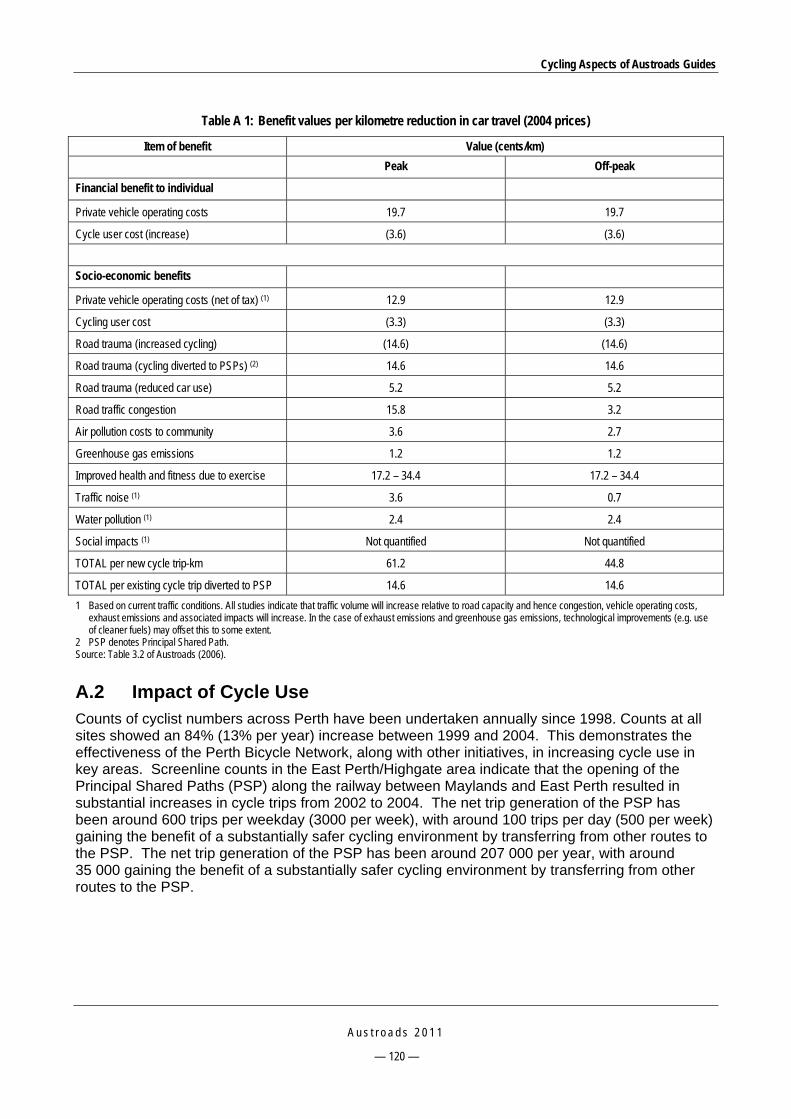
Cycling Aspects of Austroads Guides
A u s t r o a d s 2 0 1 1
— 120 —
Table A 1: Benefit values per kilometre reduction in car travel (2004 prices)
Item of benefit Value (cents/km)
Peak Off-peak
Financial benefit to individual
Private vehicle operating costs 19.7 19.7
Cycle user cost (increase) (3.6) (3.6)
Socio-economic benefits
Private vehicle operating costs (net of tax) (1) 12.9 12.9
Cycling user cost (3.3) (3.3)
Road trauma (increased cycling) (14.6) (14.6)
Road trauma (cycling diverted to PSPs) (2) 14.6 14.6
Road trauma (reduced car use) 5.2 5.2
Road traffic congestion 15.8 3.2
Air pollution costs to community 3.6 2.7
Greenhouse gas emissions 1.2 1.2
Improved health and fitness due to exercise 17.2 – 34.4 17.2 – 34.4
Traffic noise (1) 3.6 0.7
Water pollution (1) 2.4 2.4
Social impacts (1) Not quantified Not quantified
TOTAL per new cycle trip-km 61.2 44.8
TOTAL per existing cycle trip diverted to PSP 14.6 14.6
1 Based on current traffic conditions. All studies indicate that traffic volume will increase relative to road capacity and hence congestion, vehicle operating costs, exhaust emissions and associated impacts will increase. In the case of exhaust emissions and greenhouse gas emissions, technological improvements (e.g. use of cleaner fuels) may offset this to some extent.
2 PSP denotes Principal Shared Path. Source: Table 3.2 of Austroads (2006).
A.2 Impact of Cycle Use Counts of cyclist numbers across Perth have been undertaken annually since 1998. Counts at all sites showed an 84% (13% per year) increase between 1999 and 2004. This demonstrates the effectiveness of the Perth Bicycle Network, along with other initiatives, in increasing cycle use in key areas. Screenline counts in the East Perth/Highgate area indicate that the opening of the Principal Shared Paths (PSP) along the railway between Maylands and East Perth resulted in substantial increases in cycle trips from 2002 to 2004. The net trip generation of the PSP has been around 600 trips per weekday (3000 per week), with around 100 trips per day (500 per week) gaining the benefit of a substantially safer cycling environment by transferring from other routes to the PSP. The net trip generation of the PSP has been around 207 000 per year, with around 35 000 gaining the benefit of a substantially safer cycling environment by transferring from other routes to the PSP.

Cycling Aspects of Austroads Guides
A u s t r o a d s 2 0 1 1
— 121 —
A.3 Benefit-cost Evaluation A conventional benefit-cost analysis framework was then applied to the PSP component of Stage 3 of the Perth Bicycle Network. For evaluation purposes, it was assumed that:
Each km of PSP constructed will generate and attract cycle trips at the same rate as the Maylands-East Perth PSP (which was 2.9 km).
Trip lengths will be substantially longer than the average cycle trip length of 2.25 km, as this figure includes a high proportion of purely local trips not served by PSPs. It was assumed that the average cycle trip length is 6.1 km, in line with the average length of cycle trips generated by TravelSmart Individualised Marketing in Perth.
The results of this conventional project evaluation demonstrate a net present value (NPV) of $75.6 million and a benefit-cost ratio of 3.3 for this project. These results have been obtained using a discount rate of 7% per annum over a 25 year project horizon, with no residual value assumed for the PSPs. The evaluation includes appropriate allowance for the maintenance costs of the PSPs under the WA Main Roads term network maintenance contracts.
A.3.1 Other Factors Affecting Level of Benefits
In addition to the level of cycle usage as identified above, the following factors will affect the actual benefits achieved by the PSP program:
Level of path usage by pedestrians. Whilst walking trips are generally substantially shorter than cycle trips, the PSPs will attract walking activity. They are adjacent to rail lines and train stations, thus serving walk access to public transport, and also serve a number of activity centres (schools, shops, employment) along the way. These benefits will be additional to those estimated above.
Concentrated promotion of new PSPs. Previous PSPs have not been given strong marketing in the area they serve. The proposed Stage 3 PSPs will be given concentrated marketing to potential users in the area. This will increase the levels of use beyond those observed for previous PSPs and, hence, those used as the basis of this evaluation.
The extent to which cycle trips replace trips other than car driver. The evaluation has been based on all new cycle trips being converted from car driver trips (i.e. each cycle trip means one less car on the road). In practice, there may be some substitution from other modes, although this is least likely for walk (as walk trips are short) and public transport (as the main ‘competition’ is with rail (for which trips are longer than average, so more likely to be beyond typical cycling distance – in 1986 (the most recent travel survey data available for Perth) only 14% of train trips were less than 5 km and 30% less than 10 km).
That leaves car passenger trips, a proportion of which (including driving children to and from school and other activities) are undertaken solely for the benefit of the passenger and involve two car trips (there and back) for each passenger trip. For those previous car passenger trips where the driver still has to travel, this evaluation will overstate the benefits of the substitute cycle trip, as the car will still be on the road for the same amount of time. However, for those where the driver no longer has to travel, the evaluation will understate the benefits by a factor of two, as two car trips are removed for each cycle trip.
Given that car occupancy rates in Perth are low (around 1.2, on average) and around 40% of car passenger trips are for education (mainly school) purposes, the net impact of substitution for car passenger, rather than car driver trips is likely to be small.
Cycling Aspects of Austroads Guides
A u s t r o a d s 2 0 1 1
— 122 —
Overall, it is likely that the factors indicating that the evaluation will underestimate benefits, including the pre-existing declining trend in cycle usage, will outweigh any factors leading to overestimation.
A.4 An Overview of this Bicycle Example The PSP component of the proposed Stage 3 of the Perth Bicycle Network has been demonstrated to generate user and community benefits in excess of the costs of building the facilities. A benefit-cost evaluation, using conventional transport project assessment methodology has calculated a project NPV of $75.6 million and a BCR of 3.3.
This is likely to be a conservative value as it takes no account of the additional usage likely to be generated by the extension of an incomplete network of facilities, including some missing links that will greatly enhance the range of destinations it serves.
Other components of the investment proposal are for much lower-cost facilities, including local bicycle routes and other local, rather than regional, bicycle facilities. The general increase in cyclist numbers at sites surveyed since 1998 – 99, especially those on local bicycle routes, is sufficient to justify the investment, given the substantially lower cost of these facilities.
Regional recreation paths, in particular, will also generate substantial levels of recreational walking activity, which has been acknowledged to be highly beneficial in relation to health outcomes.
Public sector proposals are increasingly required to be assessed against the triple bottom line criteria of economic, environmental and social impacts. The Perth Bicycle Network proposal demonstrates a positive outcome on:
financial/economic outcomes, primarily through savings in car operating costs and congestion costs
the environmental bottom line, through reductions in air pollution, water pollution and greenhouse gas emissions
the social bottom line, through improvements in health and fitness that more than offset any net increase in road trauma.

Cycling Aspects of Austroads Guides
A u s t r o a d s 2 0 1 1
— 123 —
APPENDIX B BICYCLE SURVEY METHODS
B.1 General Bicycle survey methods are discussed in the Guide to Traffic Management – Part 3: Traffic Studies and Analysis (Austroads 2009a), particularly Section E2 of Appendix E, from which the following information is sourced. Austroads (2009a) also covers travel time and delay studies, behaviour and conflict studies, data analysis and results, and future developments.
B.2 Manual Bicycle Counts Manual counts consist of an observer recording the flow of cyclists past a certain point for the required time period. The most common method of collecting volume data is by manual counts of the flow of cyclists at a particular point in the traffic system. In the simplest form, the observer manually records the number of cyclists for the time period. The demands of data collection can be reduced by using mechanical, electrical or computerised tally counters.
Manual cyclist counts rely on good planning and skilled observers to ensure accurate and useful results. The number of observers will depend on the general level of traffic activity and the data-recording task. For example, if classification of cyclists (by demographic and/or direction of travel) is necessary, more observers will be required. Observation sites need to be chosen so that they provide a good view of the area but also provide protection from the weather and inquisitive people.
B.3 Questionnaire Surveys Questionnaire surveys can provide useful information on route choice, origin-destination information, characteristics of cyclists, crash history and the adequacy of bicycling facilities. Questionnaires can be mail-back, self-administered or interviewer-administered. The mail-back questionnaire is useful when the respondent has little time to answer the questions. The response to such surveys, however, can be quite low (30%) and unless information on the characteristics of the non-respondents is known, the results could be misleading. Simple, readily understandable questions will provide the highest response rate. Self-administered questionnaires are completed by cyclists (or pedestrians) at the location where they are handed out. For this technique to be successful the respondent must be captive and not pushed for time. As with the mail-back survey, the questions must be simple and easily understood. The on-site interview involves an interviewer asking the cyclist (or pedestrian) a series of questions, and recording the answers. Again, the respondent must not be pressed for time and the questions asked should be kept to a minimum. The advantages of this technique are an increased response rate and the ability to further explain difficult questions.
Another form of questionnaire is the household or workplace survey. These types of surveys can be used to collect considerable information on trip purpose, route and origin-destination and socioeconomic characteristics. Household surveys are expensive to undertake, particularly on a random sample of the population because cycling is a relatively rare activity.
An important factor to keep in mind when preparing questionnaires is the use of appropriate definitions. For example, one problem area is the definition of a trip. A trip can be defined as a one-way movement of a person or vehicle between two points for a specific purpose.

Cycling Aspects of Austroads Guides
A u s t r o a d s 2 0 1 1
— 124 —
B.4 Bicycle Detection Inductive loop detectors are commonly used to detect vehicles but can also be used to detect bicycles. The loops, which are buried just below the surface of the road or cycle way record metallic objects passing over due to a change in the inductance. Bicycles have a lower metal content than vehicles. Bicycle inductive loop detectors therefore need to be more sensitive to produce acceptable results.
Piezo-detectors can also be used to detect bicycles. Piezo materials change electrical characteristics when subjected to mechanical deformation caused by pressure. The deformation can cause a change in resistance (piezo-resistive) or the generation of a charge (piezoelectric). The piezo-resistive sensor can detect a bicycle at low to zero speeds, whilst the piezoelectric sensor is not effective at very low speeds.
As with the detection of pedestrians, microwave, infra-red, ultrasonic and laser detection methods can also be used to detect bicycles. Again, these types of sensors may not provide the required accuracy due to difficulties in distinguishing between closely spaced bicycles.
B.5 Video Video recordings can be analysed to determine bicycle flow rates, speeds and headways. The time stamp of the video including the frame number allows an accurate time recording. A technique by Khan and Raksuntorn (2001) automatically determines bicycle-flow data and could greatly simplify the study of bicycle-flow characteristics. The technique estimates bicycle location data by transforming screen coordinates of video frames to ground or roadway coordinates. The process is called rectification and enables automatic recognition of location and hence speed and acceleration data.
Further research is needed in this important area and imaging technologies are expected to continue to improve.

Cycling Aspects of Austroads Guides
A u s t r o a d s 2 0 1 1
— 125 —
APPENDIX C HUMAN POWERED VEHICLES Although the bicycle is the standard vehicle for the design of facilities, the use of tandem bicycles, tricycles and other ‘pedal powered vehicles' may be popular in some areas and an allowance for these vehicles may be appropriate in the design of some facilities (refer to the Guide to Road Design – Part 6A: Pedestrian and Cyclist Paths, Austroads 2009m).
There is limited information available on the needs, and operating characteristics of these vehicles, and in particular on their performance from the perspective of road and path design, or in relation to traffic management and safety. Therefore designers should make their own assessment of the required measures that need to be taken, accounting for the local use of these vehicles.
The aspects listed in Table C 1 may be relevant.
Table C 1: Human powered vehicle (HPV) – facility design considerations
Issue Details
Sight distance Consider low cyclist eye height (as low as 0.7 m above riding surface in some instances).
Braking performance Due to factors such as the low centre of gravity and braking system, braking performance of a recumbent tricycle can be significantly more effective than a standard bicycle. Conversely, tandem bicycles may have a lesser performance.
Median or refuge width Additional length of some HPVs may necessitate special consideration.
Turning paths Refer to Table C 2.
Width (of road and path facilities) Use vehicle design envelope equal to difference in inner and outer turning path radii, plus 0.3 m (0.4 m for tandem). If greater than bicycle design envelope width then increase path or road treatments accordingly.
Path terminals Give due allowance for lesser turning capabilities and in particular avoid chicanes.
Speed May be relatively high for tandem bicycles. May be lower for elderly cyclists, or cyclists with a disability.
Gradients Path gradients may have to be flatter for elderly cyclists, or cyclists with a disability.
Education Make available relevant advice e.g. conspicuity for low vehicles.
Source: Table C2 1 of Austroads (2009m).
The following example vehicle dimensions may be helpful as a guide.
Table C 2: HPV dimensions
Overall vehicle width (m)
Inner turning path radius (m)
Outer turning path radius (m)
Length (m)
Recumbent touring tricycle (Greenspeed) 0.9 1.4 2.3 1.95
Tandem recumbent touring tricycle (Greenspeed) 1.0 3.1 4.1 3.5
Tandem bicycle (Cannondale) 0.56 1.85 2.55 2.45
Bicycle with two wheel trailer (Coolstop) 0.82 0.7 1.85 2.67
Bicycle with BOB trailer (i.e. baby on board) 0.56 0.9 1.6 2.8
Bicycle with hitch-bike (Thorogood) 0.56 1.7 2.55 1.7
Source: Table C2 2 of Austroads (2009m).
Cycling Aspects of Austroads Guides
A u s t r o a d s 2 0 1 1
— 126 —
APPENDIX D BICYCLE SAFETY AUDIT CHECKLIST
D.1 Introduction In accordance with the Austroads road safety audit process (Guide to Road Safety – Part 6: Road Safety Audit, Austroads 2009o) it is appropriate that audits of bicycle routes and other facilities are conducted at various stages from planning through to construction, and in relation to existing infrastructure.
Whist Austroads (2009o) provides considerations for cyclists during various stages of road safety audit, the lists of items in the sections below (sourced from Appendix C of Guide to Road Design – Part 6A: Pedestrian and Cyclist Paths, Austroads 2009m) represent the possible contents of a checklist to assist the identification of relevant safety issues or concerns associated with bicycle facilities on roads and paths. It is unlikely that they include all of the issues that are of relevance or concern to cyclists, particularly given the wide variation in construction and design practice, and the conditions that exist.
It is therefore essential that personnel conducting audits of bicycle facilities are experienced and knowledgeable about the provision of bicycle facilities.
Individual items provided in the lists may be applicable during several audit stages or may only relate to existing infrastructure.
Where existing infrastructure is to be audited, it is important that to some degree the audit is performed on a bicycle and on foot. The type of bicycle used should be representative of the most common type in the region of the audit, but should not have a suspension system or tyres thicker than 32 mm.
Similarly, it is important that safety audit personnel ride at speeds typical of most users – which may be in excess of 25 km/h. Riding at slower speeds may not reveal potential problems such as geometric limitations or pavement surface defects.
Section D.2 is generally applicable to roads, paths and intersections. The requirements that relate mainly to either paths or roads are provided in Section D.9 and Section D.10 respectively.
In so far as roads are concerned, it is assumed that general road safety auditing processes exist, and hence the lists below represent additional considerations for bicycles.
D.2 General Requirements for Roads and Paths Are the designated crossing points and routes appropriate and acceptable to meet the
required cyclist demand?
Are the characteristic bicycle use patterns accommodated (i.e. categories of cyclists, volumes, times of travel)?
Do the proposals account for surrounding bicycle network deficiencies and opportunities?
Do consistent and suitable provisions exist for the respective categories of cyclists anticipated along the route, or can they be achieved; for instance, is a path required for children and inexperienced cyclists?
Are grade separated or controlled crossings required?
Are traffic calming or local area traffic management measures required? (refer to the Guide to Traffic Management: Part 8 – Local Area Traffic Management) (Austroads 2008b).

Cycling Aspects of Austroads Guides
A u s t r o a d s 2 0 1 1
— 127 —
Are the requirements of local codes of practice met?
D.3 Alignment and Cross-section Does the cross-section of the lane/path facility safely accommodate the anticipated cyclists?
Are stopping sight distances adequate for all traffic, accounting for paths, roads, driveways, railways etc.?
Are sight lines applicable to the operation of cyclists obscured by obstacles such as signs, trees, pedestrian fences and parked cars?
Is the horizontal and vertical alignment suitable? If not, are warning signs installed?
Are there any sections of riding surface which may cause confusion for users, e.g.:
— Is alignment of the riding surface clearly defined, particularly at unexpected bends or for dark conditions?
— Have disused pavement sections been removed or treated?
Is sufficient route information or guidance provided?
Does the design avoid or minimise the need for cyclists to slow or stop?
Do hazardous conditions (e.g. concealed intersecting paths, curves) exist at the bottom of steep gradients?
D.4 Signs, Delineation and Lighting Are all necessary pavement markings provided?
Are there any redundant pavement markings? Have redundant pavement markings been properly removed?
Are all necessary regulatory, warning and direction signs provided and located appropriately? Are they conspicuous and clear in their intent? Are they at a safe distance/height with respect to the riding surface?
Are signs in good condition and of an appropriate standard?
Are there any redundant signs?
Are fixed objects close to or on the path (trees, fences, holding rails, etc.) treated to ensure visibility at night (e.g. painted white and fitted with reflectors or reflective tape)?
Are pavement markings clearly visible and effective for all likely conditions (e.g. day, night, rain, fog, rising or setting sun, oncoming headlights, light coloured pavement surface, poor lighting)?
Are user movements obvious or delineated through intersections?
Is public lighting of facilities required? Is the lighting design satisfactory, particularly at tunnels, underpasses and areas of high pedestrian activity? Is it operating satisfactorily?
Are raised pavement markers recessed flushed with the surface or located outside of the paths of travel of cyclists, or outside of bicycle lanes?
Are thermoplastic markings chamfered?
D.5 Riding Surface Is the riding surface suitable for cycling?

Cycling Aspects of Austroads Guides
A u s t r o a d s 2 0 1 1
— 128 —
Is the riding surface and edges smooth and free of defects (e.g. grooves, ruts or steps) which could affect the stability of cyclists or cause wheel damage?
Is the pavement design/construction of a satisfactory standard?
Can utility service covers, grates, drainage pits etc., be safely negotiated by cyclists?
Are smooth and flat gutters/channels provided at stormwater drainage pit inlets?
Is the riding surface free of loose materials (e.g. sand, gravel, broken glass, concrete spills)?
Is there suitable protection to prevent sand or other debris from depositing on the riding surface?
Does the riding surface have adequate skid resistance, particularly at curves, intersections, bridge expansion joints and railway crossings?
Is the riding surface generally free of areas where ponding or flow of water may occur?
Is special protection required to prevent cyclists from running off the riding surface?
D.6 Vegetation, Maintenance and Construction Is suitable access for cycling available during maintenance and construction activities?
Are all locations free of construction or maintenance equipment?
In the absence of an appropriate and regular maintenance program:
— Is there a possibility of the encroachment of grasses into bituminous riding surfaces (e.g. kikuyu) or similar circumstances that could result in poor edge conditions or pavement degradation?
— Do thorn bearing grasses (e.g. caltrop) exist, or are they likely to be introduced adjacent to the riding surface?
— Are channels, kerb slots or similar treatments over which cyclists ride, located under deciduous trees etc., or otherwise likely to experience a build up of debris due to poor drainage conditions?
Will crack sealing processes or the application of spray seals result in the presence of loose/granular material/sand on the riding surface?
Does landscaping allow adequate clearances, sight distance etc, and will these be maintained given mature plant growth?
Could personal security of path users be adversely affected due to the position of bushes and other landscape features?
Is landscaping required as a wind break?
Will the positioning of trees and the species used contribute to the degradation of the pavement (e.g. through undermining or moisture variation)?
D.7 Traffic Signals Are separate pedestrian and/or bicycle phases provided where necessary?
Do traffic signals operate correctly? Are signal displays located appropriately for all users?
Does the design of the signals prevent conflicting motor vehicle movements during crossing phases for pedestrians and cyclists?

Cycling Aspects of Austroads Guides
A u s t r o a d s 2 0 1 1
— 129 —
Where a permanent demand for individual phases does not exist, have suitable detection facilities been provided for cyclists? Are these operating satisfactorily?
Are inductive detector loops provided for bicycle users, are they located appropriately, of a suitable design and do they operate correctly for bicycles in the various stopping positions?
If push-button actuators have been provided, are they located to allow convenient and legal operation from the normal stopping position (e.g. on the left of riding surface or kerb ramp, behind stop line)? Do they operate correctly?
Are phasing and phase times acceptable? Are suitable warning signs or guidance for cyclists erected where intersection crossing times are insufficient?
D.8 Physical Objects Are fences, safety barrier or other objects located within 1.0 m of the path(s) of cyclists:
— free of sharp edges, exposed elements or corners so as to minimise the risk of injury to cyclists in the event of the feature/object being struck by a bicycle?
— designed to minimise the potential for bicycle handle bars or pedals to become caught in the feature should an errant bicycle collide with it?
If there are any obstructions located adjacent to the paths of cyclists, are they adequately delineated?
Are clearances to the operating space of cyclists acceptable?
D.9 Paths This section should be read in conjunction with Section D.2.
D.9.1 General
Are automatic reticulation systems timed to avoid periods of significant path use? Do sprinklers spray away from the path (rather than across it)?
Do irrigation hoses need to be placed across path surfaces?
Are provisions for car parking in the vicinity of the path satisfactory in relation to the operation and safety of path users?
Are there any potential problems of conflict between the various path users (e.g. pedestrians and cyclists)?
Is the path subject to flooding? If so, are warning signs provided and located appropriately?
D.9.2 Alignment and Cross-section
Where a path is located adjacent to a road, is there sufficient separation and/or protection from the carriageway?
Are adequate overtaking opportunities provided?
Is the path width, at structures or otherwise, adequate for the likely usage levels of pedestrians and cyclists?
Is the geometric alignment and gradient satisfactory?
Is the design speed appropriate?
Is path crossfall suitable for the anticipated path users?

Cycling Aspects of Austroads Guides
A u s t r o a d s 2 0 1 1
— 130 —
Is the crossfall steep enough to adequately drain the path and prevent ponding on the surface, while being flat enough to be comfortable for pedestrians?
D.9.3 Intersections
If justified, is path priority assigned to path users at road crossings?
At intersections with busy roads, are appropriate facilities provided, e.g. traffic signals, underpass, overpass or median refuge, to allow path users to safely cross? Are the intersection controls satisfactory?
Is the location of road/path or path/path intersections satisfactory and obvious with respect to horizontal and vertical alignment?
Is the presence of intersections obvious to road/path users?
Is a refuge required at road crossings? Would it adversely affect (e.g. squeeze) cyclists travelling along the road?
In relation to path entry controls:
— Are terminal devices required? If so, does the device design meet the requirements of this guide?
— If central holding rails or bollards exist, is there a legitimate reason why they are needed, and if so is there sufficient pavement width either side?
Are kerb ramps adequate and suitable for all users (width, slope, flush surface)? Are turning radii adequate?
Are holding rails provided? Are they positioned so as to not unduly interfere with access for cyclists and other users (consider tandem bicycles, bicycles with trailers etc.)?
Are the controls associated with path/path intersections satisfactory?
D.10 Roads This section should be read in conjunction with Section D.2.
D.10.1 General
Are bicycle lanes required?
Are bicycle lane widths or the left traffic lane widths adequate to accommodate cyclists?
Can sufficient space be obtained? Are there any squeeze points for cyclists?
Does the construction of the lane facility conform to this guide and other relevant standards?
Are special provisions required along curving roads?
Are road markings for cyclists suitable and adequate, and do they meet relevant standards?
On controlled access roads, is a commuter path required within the reservation?
Are local area traffic management treatments appropriate for bicycles?
Are drainage pit covers flush with the surface or are there level differences that could be hazardous to cyclists and pedestrians?
Is the positioning of bicycle pavement symbols potentially hazardous to motorcyclists?
Are sealed shoulders at least as smooth as traffic lanes?
Cycling Aspects of Austroads Guides
A u s t r o a d s 2 0 1 1
— 131 —
D.10.2 Intersections
Are the intersection treatments appropriate?
Are there any common cyclist movements (legal or otherwise) that differ from typical traffic movements? Are these likely to be anticipated by other traffic? Can these movements be made safely and if not what remedial measures are required?
Are ‘head-start’ storage areas required due to conflicting manoeuvres of bicycles and other traffic, or due to high cyclist volumes?
Are special provisions for cyclists required at roundabouts?
Are continuity lines marked where appropriate?
Are grated drainage pits that are potentially hazardous to cyclists and pedestrians located within the road/path intersection or within the turning path of cyclists (i.e. radii in the corners of the intersection)?
Are grated pits on paths or in close proximity to paths properly designed so that they cannot trap bicycle wheels?
Cycling Aspects of Austroads Guides
A u s t r o a d s 2 0 1 1
— 132 —
APPENDIX E EXAMPLE OF BICYCLE SAFETY AUDIT
E.1 Background The following example is taken from Section 7.7 of the Guide to Road Safety – Part 6: Road Safety Audit (Austroads 2009o). Shared bicycle/pedestrian paths have been developed beside a major road. A project to convert the major road to full freeway standard has involved modifications to bicycle facilities. The audit took place at the pre-opening stage of the freeway conversion project. Auditing the bicycle facilities was specifically required as part of the audit of the whole project.
E.2 Paths on the North/East Side On the south side of Toorak Road there is poor sight distance between the link path from
Toorak Road and the main path to the north (under the bridge). The acute angle of connection of these two paths makes movements between them very difficult.
Recommendation 1: Consider options for improving safety at the junction of the paths, such as provision of signs to warn cyclists/pedestrians of the junction. Consider relocation and realignment of the two paths about 5 – 10 m further from Toorak Road. (Important).
At a number of locations there are posts and ends of rails at the edge of the path that are a hazard to any errant cyclist.
Recommendation 2: Review the design and location of all posts and rails beside the path and shield or modify those in exposed locations. (Important).
The Keep Left markings at bends along the path include a left-angled arrow above the words. Northbound, just south of Toorak Road, the arrow gives a misleading message about alignment of the path and whether cyclists/pedestrians should use the link path to Toorak Road, which is on the right.
Recommendation 3: Remove the left pavement arrow from the Keep Left messages, or locate it across the centreline.
At Toorak Road, the shared path crosses the road at pedestrian signals. At this point the path beside the road is too narrow and is overgrown (Figure E 1).
Recommendation 4: Widen the path beside Toorak Road.

Cycling Aspects of Austroads Guides
A u s t r o a d s 2 0 1 1
— 133 —
Source: Figure 7.20 of Austroads (2009o).
Figure E 1: The path to pedestrian signals is narrow and overgrown
E.3 Paths on the South/West Side The shared path west of Burke Road (adjacent to Carroll Crescent) has a broken surface
near the Gardiner railway station.
Recommendation 5: Repair and maintain surface of the shared path. (Important).
There is loose gravel on the shared path under the Tooronga Road bridge that is a safety hazard for cyclists.
Recommendation 6: Remove the loose gravel from the shared path. Seal the path. (Important).
There is no footpath across the railway line where the shared path reaches Toorak Road (Figure E 2).
Recommendation 7: Provide a footpath across the railway line on the south side of Toorak Road. Link it to the paths on each side. (Important).

Cycling Aspects of Austroads Guides
A u s t r o a d s 2 0 1 1
— 134 —
Source: Figure 7.21 of Austroads (2009o).
Figure E 2: The link path from Toorak Road joins at an acute angle, with restricted sight distance

Cycling Aspects of Austroads Guides
A u s t r o a d s 2 0 1 1
— 135 —
APPENDIX F BICYCLE PARKING REQUIREMENTS
F.1 General Bicycle parking requirements are discussed in the Guide to Traffic Management – Part 11: Parking (Austroads 2008c), some of which are presented below.
Planning codes and policies in various jurisdictions may contain certain mandatory requirements for bicycle parking and other end of trip facilities such as showers and lockers in new developments. These facilities may also be installed as a result of the outcomes of local strategic bicycle plans, urban planning strategies or based on specific needs (Section 6.8.3, Austroads 2008c).
Bicycle parking along a street (Section 7.8.5, Austroads 2008c) is generally provided in the form of bicycle rails. These facilities should be located parallel to the kerb or footway unless a footpath extension is provided, and on both sides of the road where demand warrants it. The minimum clearances should be as follows:
The clearance between a parked bicycle and the edge of the roadway should be at least 600 mm or 1000 mm if the speed limit on the roadway is greater than 60 km/h.
On a footpath, the minimum clearance for passage of pedestrians between a parked bicycle and any other obstruction is 1200 mm (unless specified otherwise by legislation) with a greater clearance needed when there are high volumes of pedestrians.
When considering the provision of new or modified car parking arrangements, practitioners should also consider the needs for additional facilities for cycling as well as the methods to minimise the impact of car parking on existing or future cycling use. This would normally include consideration of any strategic bicycle plan for the affected road(s) and, where practicable, ensuring good visibility for drivers including designing the layout of parking areas in such a way so as to reduce the chance of car doors being opened into the path of oncoming cyclists.
F.2 General Requirements of Devices In general, every bicycle parking facility should:
enable wheels and frame to be locked to the device without damaging the bicycle
be placed in view of staff, customers and passers by or covered by TV cameras
be located outside pedestrian movement paths, segregated where possible, and possibly allowing extra footpath width in anticipation of cycles chained to poles
be easily accessible from the road
be arranged so that parking entries and exits will not damage adjacent vehicles
be protected from manoeuvring motor vehicles and opening car doors
be as close as possible to the cyclist’s ultimate destination
be well lit by appropriate new or existing lighting
be protected from the weather
be attractive and designed to blend in with the surrounding environment
be appropriately signed

Cycling Aspects of Austroads Guides
A u s t r o a d s 2 0 1 1
— 136 —
be well maintained and kept free from graffiti: it should be noted that recurring maintenance costs should receive as much consideration in budgeting as the initial construction and installation costs
have a convenient cut-down crossing (pram/kerb ramp) near the bicycle parking facilities.
Monitoring of demand/use should be carried out regularly in order to determine the effectiveness of the end of trip facility.
F.3 Location of Bicycle Parking Facilities Bicycle parking facilities should be provided in small clusters within 100 m of common commuting and recreational destinations of bicycle trips such as schools, shopping centres, railway stations, bus terminals/interchanges, work places, sports grounds, etc.
It should be noted that if parking facilities are not conveniently located, cyclists will ignore them and continue the disorderly practice of securing bicycles to nearby railings, posts, seats, parking meters, trees etc. In particular, short-term bicycle parking needs to be convenient if it is to be effective.
F.4 Types of Parking Devices F.4.1 General
Bicycle parking facilities are classified by security level as shown in Table F 1.
Table F 1: Classification of bicycle parking facilities
Class Security level Description Duration of parking Main user type
1 High Fully enclosed individual locker.
All day and night. Bike and ride commuters at railway and bus
stations.
2 Medium Lockable enclosure, shelter or compound fitted
with class 3 facilities where cyclist is
responsible for locking their bicycle within the communal enclosure.
All day. Regular employees, students, regular bike and
ride commuters.
3 Low Bicycle rails or racks to which both the bicycle
frame and wheels can be locked .
Short to medium term.
Shoppers, visitors, employees of workplaces where security supervision of the facility is provided.
Source: Table C9 2, Commentary 9, Austroads (2008c).
F.4.2 Bicycle Lockers
Bicycles lockers (Figure F 1) offer the highest level of bicycle security currently available. They also have the added advantage that helmets and other gear can be securely stored along with the bicycle. Bicycle lockers restrict access to one user and are most effective in public places where there is a high risk of theft or vandalism. They are most commonly located at railway stations and bus terminals to encourage the use of multi-modal travel, as well as at apartments, residential complexes, and university residences. They should be situated in a well-lit area, and fabricated from corrosion-resistant materials if close to the sea.

Cycling Aspects of Austroads Guides
A u s t r o a d s 2 0 1 1
— 137 —
It is important that the use of lockers is managed by an appropriate authority such as the managers of a shopping centre, major building, or railway station. They can either be rented to a single user for a period of time, or casual users can obtain a lock and key from the facility manager. It is also possible to manage lockers automatically with electronic access control similar to that used by some airport luggage lockers.
Source: Figure C9 1, Austroads (2008c).
Figure F 1: Example of bicycle lockers location at a bus terminal in Canberra
F.4.3 Bicycle Enclosures
Bicycle enclosures offer a medium level of security in that while the owner can lock the bicycle within the enclosure, other users also have access to the enclosure. These are usually located at railway stations, public transport terminals, workplaces, universities/TAFE colleges, schools, apartments/residential complexes and university residences. Enclosures can be a room, a compound, or a purpose-built area containing groups of bicycle parking rails, and fitted with a roof for increased security and weather protection. Public lighting is desirable where they are located in a public place and used after dark.
Enclosures should be lockable to prevent unauthorised access. If restricted keys are used, unauthorised copying will be prevented. Electronic access control may also be suitable particularly if the building already has such a system. It is important to ensure that a nominated person is responsible for managing access issues and distributing keys or access cards to the enclosure. If a higher level of security is required, it may be possible to install a surveillance camera to monitor the door to the enclosure.
Where space is limited, an enclosure designed for vertical bicycle storage may be provided.
F.4.4 Bicycle Parking Rails
The parking rail is amongst the most versatile methods of bicycle parking currently available in that it is:
inexpensive to install and maintain
easily fabricated

Cycling Aspects of Austroads Guides
A u s t r o a d s 2 0 1 1
— 138 —
able to be located close to cyclist destinations
suited to short and medium-term parking.
Parking rails are usually located at shopping centres/markets, business districts, recreational centres/swimming pools, libraries and universities/TAFE colleges. They should be located in well-lit areas in public view, where they will not impede the opening of doors on parked cars, and where they can also be easily seen by motorists. Where possible they should be situated near buildings that have on-site security or if a high level of security is required, it may be possible to install a surveillance camera to monitor the rails.
Parking rails may come in a number of shapes and sizes and can be as ornate as the site requires as long as the rail:
supports the entire bicycle
is of a shape that allows the cyclist to lock the front wheel and frame, top bar and back wheel and frame to the rail
is manufactured from smooth steel tubing of a diameter that a u-lock can easily fit around (usually 50 mm) and is vandal resistant
has base plates welded to the bottom of each leg so that they can be bolted to a concrete surface or long enough so they can be set in concrete footings.
Parking rails can be arranged to best fit the available space. Each parking rail can accommodate two bicycles, one on each side of the rail. They can also be installed in clusters or groups to meet the parking demand. Bicycle racks may also incorporate plastic coated chains which can be secured by padlock.
The traditional ‘toaster rack’ style bicycle stands holding only one wheel have been around for a long time. They do not, however, meet the requirements of AS 2890.3: 1993 as they do not allow the frame and wheels to be locked to the rack, and can therefore damage the wheels. They should be replaced progressively giving priority to those where the security risk is greatest.
F.5 Signs and Markings Showing Location and Purpose of Parking Facilities
Information signs and pavement markings should be provided to direct cyclists to parking facilities and indicate the purpose of the facility in order to encourage their use. Lockers and other facilities must also display instructions for use.
Signs should be provided in accordance with AS 2890.3: 1993, consisting of a standard bicycle pavement symbol with an additional panel below. The message on the lower panel should normally read Bicycle lockers, Parking enclosure, Parking rails or Parking. Another message may be required in special circumstances.
It is also recommended that bicycle rails have a small bicycle pavement symbol painted on the pavement beneath to clarify the purpose of the rails or have the words ‘Bicycle Parking’ stencilled on the rail. This is usually applicable to ornate rails that may be mistaken for street art.
F.6 Bicycle Parking Provision Rates Table F 2 gives an indication of the levels of bicycle parking needed to be provided for various land uses.

Cycling Aspects of Austroads Guides
A u s t r o a d s 2 0 1 1
— 139 —
Table F 2: Bicycle parking provision
Land use Employee/resident parking spaces Class Visitor/shopper parking spaces Class
Amusement parlour 1 or 2 1 or 2 2, plus 1 per 50 m2 gfa 3
Apartment house 1 per 4 habitable rooms 1 1 per 16 habitable rooms 3
Art gallery 1 per 1500 m2 gfa 2 2, plus 1 per 1500 m2 gfa 3
Bank 1 per 200 m2 gfa 2 2 3
Café 1 per 25 m2 gfa 2 2 3
Community centre 1 per 1500 m2 gfa 2 2, plus 1 per 1500 m2 gfa 3
Consulting rooms 1 per 8 practitioners 2 1 per 4 practitioners 3
Drive-in shopping centre 1 per 300 m2 sales floor 1 1 per 500 m2 sales floor 3
Flat 1 per 3 flats 1 1 per 12 flats 3
General hospital 1 per 15 beds 1 1 per 30 beds 3
General industry 1 per 150 m2 gfa 1 or 2 – 3
Health centre 1 per 400 m2 gfa 1or 2 1 per 200 m2 gfa 3
Hotel 1 per 25 m2 bar floor area
1 per 100 m2 lounge, beer garden
1
1
1 per 25 m2 bar floor area
1 per 100 m2 lounge, beer garden
3
Indoor recreation facility 1 per 4 employees 1 or 2 1 per 200 m2 gfa 3
Library 1 per 500 m2 gfa 1 or 2 4, plus 2 per 200 m2 gfa 3
Light industry 1 per 1000 m2 gfa 1 or 2 – 3
Major sports ground 1 per 1500 spectator places 1 1 per 250 spectator places 3
Market – 2 1 per 10 stalls 3
Motel 1 per 40 rooms 1 – 3
Museum 1 per 1500 m2 gfa 1 2, plus 1 per 1500 m2 gfa 3
Nursing home 1 per 7 beds 1 1 per 60 beds 3
Office 1 per 200 m2 gfa 1 or 2 1 per 750 m2 over 1000 m2 3
Place of assembly – 2 – 3
Public hall – 1 or 2 – 3
Residential building 1 per 4 lodging rooms 2 1 per 16 lodging rooms 3
Restaurant 1 per 100 m2 public area 1 or 2 2 3
Retail show room 1 per 750 m2 sales floor 1 1 per 1000 m2 sales floor 3
School 1 per 5 pupils over year 4 2 – 3
Service industry 1 per 800 m2 gfa 1 – 3
Service premises 1 per 200 m2 gfa 1 – 3
Shop 1 per 300 m2 gfa 1 1 per 500 m2 over 1000 m2 3
Swimming pool – 1 or 2 2 per 20 m2 of pool area 3
Take-away 1 per 100 m2 gfa 1 1 per 50 m2 gfa 3
University/Inst. of Tech 1 per 100p/t students
2 per 100f/t students
1 or 2
2
– 3

Cycling Aspects of Austroads Guides
A u s t r o a d s 2 0 1 1
— 140 —
Notes:
gfa – gross floor area.
Refer to Table F 1 for Class definitions.
The dash ‘-‘ mark in the table indicates that no parking demand information is available, and therefore planners should make their own assessment of the required bicycle parking provisions on an individual project basis.
It is sometimes appropriate to make available 50% of the level of provision recommended in the table at the initial installation stage; however, space should be set aside to allow 100% provision in the event that the full demand for bicycle parking is installed.
Source: Table C2 7, Commentary 2, Austroads (2008c).
Cycling Aspects of Austroads Guides
A u s t r o a d s 2 0 1 1
— 141 —
COMMENTARY 1 It is desirable that the specific aims of a state or territory strategy:
establish a key group to administer and coordinate the implementation of the strategy
ensure that planning for cycling is integrated within overall transport and land use planning, urban development, building rules, traffic management and community planning
give priority to those areas where the existing or potential demand for cycling is highest
ensure that cyclists have suitable and legitimate access to roads and paths, where appropriate
ensure the development of programs promoting cycling as a legitimate form of transport
ensure the development of behavioural and safety awareness programs aimed at improving cyclist safety in general
ensure support for key promotional activities e.g. Bike Week, Ride to Work
ensure an appropriate legislative framework for cycling having regard to safety, good traffic engineering practice and credibility of the law
encourage cycling for the environmental, recreational and health benefits to cyclists and the wider community
reduce the frequency of bicycle crashes and the severity of injuries resulting from crashes
coordinate the provision of cycling facilities and programs across relevant agencies and organisations
develop, implement and maintain a state-wide bicycle route network incorporating metropolitan routes, interregional routes and routes within regional centres and municipalities
ensure cycling facilities and programs are readily accessible
ensure cycling facilities serve the needs of the relevant categories of cyclists
provide guidance to encourage a high level of compliance by cyclists with traffic laws, and by other road and path users in relation to cyclists, covering both educational and enforcement needs
encourage the establishment of a strong and pro-active cycling industry, including manufacturers, traders and the tourism industry operators
ensure the systematic measuring, auditing or evaluation, of programs and facilities
facilitate ongoing research and investigation of new initiatives.
COMMENTARY 2 The actions required to develop local strategic bicycle plans would usually include:
a survey of the extent and nature of cycling within the municipality or region
determination of the cycling requirements of the community
identification of factors that inhibit cycling
identification of a practical bicycle route network with appropriate links to adjacent regions or networks

Cycling Aspects of Austroads Guides
A u s t r o a d s 2 0 1 1
— 142 —
development of engineering measures and programs to overcome problems including estimated costs, time frame and an implementation plan
development of a bicycle network support requirements (e.g. bicycle parking, kerb ramps, drinking water fountains, signage)
development of encouragement and other appropriate behavioural programs, with an aim of increasing the use of cycling facilities as well as the safety of cycling, in the local area
review of law enforcement and compliance with local bylaws
review of the requirements for development applications in regard to cycling (e.g. bicycle parking and shower facilities)
review of construction and maintenance practices and educate staff responsible for these tasks, so they accommodate the needs of cyclists in their work (e.g. landscaping, roadworks and irrigation).
For the community to derive maximum benefit from its local strategic bicycle plan it is essential that the plan produce positive, practical and affordable outcomes that meet user needs.
It is suggested that the development of local strategic bicycle plans should be overseen by a steering committee comprised of representatives of:
the council
council engineering, urban planning and recreation staff
the state road authority
the police
local schools
cyclists
bicycle industry
local industry
the local community.
COMMENTARY 3 Figure C3 1 provides details relating to the design of the six intersection elements presented in Section 5.3.3 of this guide.

Cycling Aspects of Austroads Guides
A u s t r o a d s 2 0 1 1
— 143 —
Source: VicRoads (2001). Also refer to Figure C16 1, Commentary 16, Austroads (2009i).
Figure C3 1: Designing for the six intersection element