AUSTRALIAN SOCIETY OF EXPLORATION GEOPHYSICISTS · PDF fileaustralian society of exploration...
33
AUSTRALIAN SOCIETY OF EXPLORATION GEOPHYSICISTS (A.B.N. 71 000 876 040) FORMAT FOR EXCHANGE OF ELECTRICAL SURVEY DATA ASEG ESF FORMAT Developed by the ASEG Technical Standards Committee Version 001 - August 2012
Transcript of AUSTRALIAN SOCIETY OF EXPLORATION GEOPHYSICISTS · PDF fileaustralian society of exploration...

AUSTRALIAN SOCIETY OF EXPLORATION GEOPHYSICISTS(A.B.N. 71 000 876 040)
FORMAT FOR EXCHANGE OF ELECTRICAL SURVEY DATA
ASEG ESF FORMAT
Developed by the ASEG Technical Standards CommitteeVersion 001 - August 2012

TABLE OF CONTENTS
Overview.. . . . . . . . . . . . . . . . . . . . . . . . . . . . . . . . . . . . . . . . . . . . . . . . . . . . . . . . . . . . . . 1
Modifications to the standard. . . . . . . . . . . . . . . . . . . . . . . . . . . . . . . . . . . . . . . . . . . . . . . 1
Standard File Definition. . . . . . . . . . . . . . . . . . . . . . . . . . . . . . . . . . . . . . . . . . . . . . . . . . . 1Record 1: - Title. . . . . . . . . . . . . . . . . . . . . . . . . . . . . . . . . . . . . . . . . . . . . . . . . . . . 2Record type 2: - Constant Definitions. . . . . . . . . . . . . . . . . . . . . . . . . . . . . . . . . . . 2Record type 3: - Optional @Keywords.. . . . . . . . . . . . . . . . . . . . . . . . . . . . . . . . . . 2Record 4: - Column Definitions. . . . . . . . . . . . . . . . . . . . . . . . . . . . . . . . . . . . . . . . 2Record 5 to End of File: - Data Records. . . . . . . . . . . . . . . . . . . . . . . . . . . . . . . . . 3Nulls. . . . . . . . . . . . . . . . . . . . . . . . . . . . . . . . . . . . . . . . . . . . . . . . . . . . . . . . . . . . . 3Comments. . . . . . . . . . . . . . . . . . . . . . . . . . . . . . . . . . . . . . . . . . . . . . . . . . . . . . . . 3Conventions. . . . . . . . . . . . . . . . . . . . . . . . . . . . . . . . . . . . . . . . . . . . . . . . . . . . . . . 3Writing Constants, Variables and Keywords. . . . . . . . . . . . . . . . . . . . . . . . . . . . . . 4
Defined Variables and Constants. . . . . . . . . . . . . . . . . . . . . . . . . . . . . . . . . . . . . . . . . . . . 4
Obsolete Keywords for defined Variables and Constants. . . . . . . . . . . . . . . . . . . . . . . . 21
Unspecified Variables and Constants.. . . . . . . . . . . . . . . . . . . . . . . . . . . . . . . . . . . . . . . 22
Example ESF files. . . . . . . . . . . . . . . . . . . . . . . . . . . . . . . . . . . . . . . . . . . . . . . . . . . . . . 22
Support Files. . . . . . . . . . . . . . . . . . . . . . . . . . . . . . . . . . . . . . . . . . . . . . . . . . . . . . . . . . 25Boundary Files. . . . . . . . . . . . . . . . . . . . . . . . . . . . . . . . . . . . . . . . . . . . . . . . . . . . 25Channel Files. . . . . . . . . . . . . . . . . . . . . . . . . . . . . . . . . . . . . . . . . . . . . . . . . . . . . 26Collar files. . . . . . . . . . . . . . . . . . . . . . . . . . . . . . . . . . . . . . . . . . . . . . . . . . . . . . . 27Survey files. . . . . . . . . . . . . . . . . . . . . . . . . . . . . . . . . . . . . . . . . . . . . . . . . . . . . . 27Wire Files.. . . . . . . . . . . . . . . . . . . . . . . . . . . . . . . . . . . . . . . . . . . . . . . . . . . . . . . 28Waveform File. . . . . . . . . . . . . . . . . . . . . . . . . . . . . . . . . . . . . . . . . . . . . . . . . . . . 29Concatenated file.. . . . . . . . . . . . . . . . . . . . . . . . . . . . . . . . . . . . . . . . . . . . . . . . . 29
Edit History. . . . . . . . . . . . . . . . . . . . . . . . . . . . . . . . . . . . . . . . . . . . . . . . . . . . . . . . . . . . 31
ASEG-ESF Format for exchange of electrical survey data
Overview: A standard format for data exchange is required so that data can be passedbetween users in a format which allows the data to be read with minimal user input andprocessed with a minimum of additional information. Rather than defining what can’t bewritten to a file the standard defines the file structure, those pieces of information that mustbe included and associates standard meanings to common keywords. Anything else shouldbe allowed to be written to the file as long as it follows the file format and does not use a listedkeyword for another purpose. The standard should be flexible enough to allow for unforseenchanges in instrument output over time and the format should be ASCII to allow it to be bothplatform independent and durable.
The AMIRA format has become a defacto industry standard for EM and likewise the GeosoftDAT format for IP data. This has largely been because they are documented and thususeable by others. Additions to the original definitions of both formats have being added bysoftware vendors but as these are usually not documented, there has been some divergencein the format which this new standard attempts to remedy. The standard needs to allow forboth time and frequency domain data and all electrical survey types viz, EM, IP, MMR,CSAMT, MALM, SP, ERI as well as AMT and MT although there is already a SEG standardfor these two. Although the original AMIRA format was designed with IP data in mind itrequires extension to handle these data. The Geosoft IP DAT format is currently the defactostandard for IP data exchange and because of general similarity in the data types it isintended that these two formats merge to become one.
The standard is intended for all electrical survey types, borehole, surface and airborne. Thestandard has been designed so that a single ESF file can capture all the survey data as wellas all the survey metadata. However it is also flexible enough to allow linked parameter fileswhere particular survey parameters (e.g the transmitter waveform or loop layout) are verbose.If this feature is used then all the files linked in the ESF file are required in order to complywith the standard. These parameter files may be single files for each parameter type or moresimply a single file which concatenates all the individual files into a single .CON file.
Modifications to the standard: The format should not be static, however it should begeneral enough so that any future changes are backward compatible so that older versionsof software can read it. Changes to the format must be documented and easily available to anyone who needs them. A suggested mechanism to achieve this is through a standardstopic on the ASEG user web forum. Well supported changes could then be added to thestandard document generated by the Technical Standards Committee and be made availablefor download.
Standard File Definition:
The file extension for the file is .ESF
The file has a standard layout as follows;Record 1: TitleRecord type 2: Constant Definitions - multiple consecutive records allowedRecord type 3: Optional @Keywords - multiple consecutive records allowedRecord 4: Column DefinitionsRecord 5+: Data Records
1

Records 1 to 4 should only occur at the start of the file, not be repeatedthroughout the file.
In addition to these the file may contain any number of comment records
The record terminator is not defined and may be O/S dependent. e.g. Hex 0D0A -MSDOS/Windows, 0D - Macintosh, 0A - Unix. Given that most commercial IPprocessing software is MSDOS/Windows based 0D0A would be preferred.
Record 1: - Title
This consists of ASCII text of arbitrary length. It should include the version number ofthe EM/IP file format to allow for future changes which may not be backward compatibleand to draw a line between the new format and past practice. The format for declaringthe version number is VER:#### where #### is a 4 digit number starting at 0001 andhopefully never reaching 9999!
Record type 2: - Constant Definitions
This record consists of zero or more constant declarations in the formCONSTANT:VALUE or CONSTANT=VALUE. The constants should be separated byone or more spaces or tabs. Any field defined on this record is said to be a Constant.As spaces or tabs are used as delimiters neither should exist immediately after the : or= delimiter. Multiple instances of Record Type 2 are allowed as long as they areconsecutive.
Record type 3: - Optional @KeywordsAt or @ Keywords can be used instead of an external file to define array type constantssuch as window times, transmitter wire vertices, frequencies or transmitter waveform.Except in the case of very long arrays the use of @Keywords is preferred over directionto an external file. This reduces the chance of important information becoming detachedfrom the data file during de-archiving. The @Keyword must only be used at the start ofa line in the file and has the form @KEYWORD= an array of comma separatedconstants. Multiple instances of Record Type 3 are allowed as long as they areconsecutive.
Record 4: - Column Definitions
This record consists of one or more column titles which describe the data in the datarecords which follow. The column definitions should be separated by one or morespaces or tabs and can not therefore contain spaces or tabs. Any field defined here issaid to be a Variable. Because multiple instances or Record 2 or 3 are allowed the codeneeds some way to automatically recognise a Column Definition line. The labels usedin the Column Definition line should therefore not include the characters : or = as atleast one of these will be used in Records 2 or 3. The parsing code can then read a lineof text and check for the existence of : or = and if not found assume the line is Record4
2
Record 5 to End of File: - Data Records
Each data record consists of one or more data values. Data values may contain anycharacters except spaces and tabs. They are separated by one or more spaces and/ortabs. There should be one data value for each column title. There is no requirement thatdata values line up underneath column titles. The nth value is assigned to the nthcolumn variable. There may not be any missing values. If a value is unknown, a nullvalue must be entered
Nulls:
A null value may be represented in any of the following ways:
1. Declared in the header using the Keyword NULL: followed by a Constantrepresenting the null value. This is the preferred method however for backwardcompatibility with AMIRA and Geosoft the following null options will berecognised. New software should write option 1 not the backward compatibleoptions.
2. An asterisk (*).
3. The numeric value 1.0e33. As this value is numeric the formatting is notimportant. For example 1e33, 1.0E+033 etc. are all null values.
4. A string consisting of a minus sign followed by six or more nines. Since this is astring, the formatting is important. -999999 or -999999999999 are both nulls, but-0.9999999999e10 is not a null value.
Comments:
Any line which begins with a forward slash (/) followed by a space. For backwardcompatibility a back slash (\) is also allowed but should not be used on new data files.The requirement to have a space following the forward slash allows for slash Keywordse.g. \TIMES to indicate that windows times will follow. Slash keywords should bedeprecated and replaced with @ Keywords. This should reduce the chances of softwarewriters confusing the slash and slash Keywords.
Conventions:
The units of certain variables should be a constant, e.g. all Times should be inmilliseconds, Current should be in Amps and loop areas or moments should be insquare metres even if the distance units are imperial.
All times are relative to time zero which is defined as the start of transmitter turn off viz.The top of the ramp. For processed galvanic electrical data electrode C1 is the currentelectrode closest to the potential electrodes. Electrode P1 is the potential electrodeclosest to the current electrodes. If using Pole arrays C2 and or P2 should be theremote electrode and may be specified as constants in Record 2. For field data thisordering may not always be achievable however where possible this ordering conventionshould be followed.
3
Writing Constants, Variables and Keywords:Keywords, Constants and Variables must not contain spaces, tabs, a colon (:) or anequals sign (=). Quotes or brackets are not considered to be special characters.
Defined Variables and Constants:
In the following table the AMIRA or Geosoft defined fields are shown in black, existingalternates for these in green and proposed new fields in blue. New code should output thepreferred rather than alternate Keyword. The case of the Keywords is not defined andKeywords should be designed to avoid ambiguity if the input line has its case changed by theinput software.
This keyword list is not intended to be a limit what can be written to a file - any relevant information should be able to be written to the file. This keyword list is intended to provide astandard meaning to commonly used variables and constants so that they have a consistentmeaning across different files and so that parsing programs can be adapted to recognisethem.
Keyword (preferred)
Description - Variable or Constant Mandatory Keyword(alternate)
ARRAY Constant - The array type used to acquire thedataExamples - 4 letter acronyms preferred;DPDP - dipole dipolePDPD, PDP - pole dipoleDPPL - dipole polePLPL - pole poleGRAD - gradientSCHL - schlumbergerWENN - wennerUSER - other than above. If used then allelectrode co-ords must be specified
Yes (IP)
AZIMUTH Variable - Rotation of the direction of a surveytraverse clockwise from North. Specified indegrees. The convention for North (grid ormagnetic) is specified in NORTHTYPE
No AZIM
BARALT Variable - Barometric Altitude inUNITS.LENGTH if airborne
No BAROALTBAROMETRICALTIMETER
BFIELD Constant - Yes/No answer if data is Bfieldresponse. Overrides any implied response inUNITS.EMIP.
Yes ifBField
BOUNDARY Constant or @Keyword - Array of Lat/Long pairsdescribing the outer limits of the survey. To beused for automatically making polygons for GISindexing. Lat/Longs in decimal degrees
No
4

Keyword (preferred)
Description - Variable or Constant Mandatory Keyword(alternate)
BOUNDFILE Constant defining filename containing BoundaryInformation in decimal degrees
No
C1X Variable - X location of the first currentelectrode. X can either be station along line ordown hole in which case Y for all electrodes areobtained from the line variable or it can be theeasting (local or UTM) in which case Y must bespecified as a variable
Yes(IP) FX1, C1, F1, F1X,T1X, TX1,C1E,C1EAST,C1_STATION
C1Y Constant or Variable - Y location of the firstcurrent electrode. If a constant this could beequivalent to either a line number or a northingfor a remote pole electrode if a variable Yshould be the northing (local or UTM)
Yes (if IP &ARRAY isUSER)
FY1, F1Y, T1Y,TY1,C1N,C1NORTH,C1_LINE
C1ZC1D
Constant or Variable - Z location of the firstpotential electrode where Z is the elevation,increasing upwards If borehole data and C2D isused D is depth positive down
No M1Z,R1Z,C1LEVEL
C2X Constant or Variable - X location of the secondcurrent electrode. X can either be station alongline or down hole in which case Y for allelectrodes are obtained from the line variable orit can be the easting (local or UTM) in whichcase Y must be specified as a variable
Yes(IP) FX2, C2, F2, F2X,T2X, TX2,C2E,C2EAST,C2_STATION
C2Y Constant or Variable - Y location of the secondcurrent electrode. If a constant this could beequivalent to either a line number or a northingfor a remote pole electrode if a variable Yshould be the northing (local or UTM)
Yes (if IP &ARRAY isUSER)
FY2, F2Y, T2Y,TY2, C2N,C2NORTH,C2_LINE
C2ZC2D
Constant or Variable - Z location of the secondcurrent electrode where Z is the elevation,increasing upwards. If borehole data and C2D isused D is depth positive down
No F2Z,T2Z,C2LEVEL
CnXCnYCnZCnD
Constant or Variable - location of the nth currentelectrode (N>2)
No
CnE_UTMCnN_UTMCnELEVCn_LATCn_LONG
Constant or Variable - location of the nth currentelectrode (N>0) in UTM space, datum to bedefined using Keyword DATUM If in Geographicco-ords Lat/Long to be given in decimal degrees
No TXEASTnTXNORTHnTXELEVn
CHANNELFILE Constant - Name of User defined channel filewith window timese.g. CHANNELFILE=MYINST.CHNBecause this requires a separate file which maybecome detached from the data file the use ofthe @Keywords @TIMESSTART and@TIMESEND is recommended
No
5

Keyword (preferred)
Description - Variable or Constant Mandatory Keyword(alternate)
CHn Variable - Amplitude of measured field for EM, amplitude of secondary voltage normalised bythe primary voltage at window n for TDIP ormagnitude and phase of CR data. The originalGeosoft format allowed for data too noisy toread with the Keyword TN. In the digital age thisshould be unnecessary and only retained forbackward compatibility. The use of CH ratherthan IP converges with the AMIRA format. Ifusing CH then n=1..max number of windowsrecorded if using IP n=0 to max-1 number ofwindows recorded. This conforms with both theAMIRA and Geosoft standards. CHn preferred.
Yes forTimeDomain
IPn, Mn, [n],AResn.
COLE_C Variable - Cole-Cole c exponent No
COLLARFILE Constant - Collar file name for down hole data.File has a header line using standard keywordslisted here for hole, east, north and rl. The collarwill normally be the top of the hole but may be awedge point for surveys that start with depth 0at the wedge.
No
COMPONENT Variable - Direction in which EM field ismeasured. Maintain a right hand rule.General surface surveysX = Horizontal in an EAST direction.Y = Horizontal in a NORTH direction.Z = Vertical. With polarity positive upwards.Down HoleA = Axial. Along the hole with polarity positivetowards the collar. i.e a vertical downward holewill have A positive up, a vertical upward holewill have A positive down.U = Perpendicular to A and V in a vertical planecontaining the hole and positive away fromgravity (up).V = Perpendicular to A and U in a horizontalplane. Looking into the hole from the collar,positive at 9 o’clockFEMHCP = Horizontal Co-PlanarVCP = Vertical Co-PlanarVCA = Vertical Co-AxialFor backward compatibilityC = Same as Z but implies Coincident Loopdata.I = Same as Z but implies In Loop data.
No CCMPCOMP
6

Keyword (preferred)
Description - Variable or Constant Mandatory Keyword(alternate)
CONFIG Constant - Survey configurationCOINCIDENTSynonyms
COINCIDENT_LOOPCOINC_L
DOWNHOLESynonyms
DOWN_HOLELTX_DHRDRILLHOLEBOREHOLE
FIXEDLOOPSynonyms
FIXED_LOOPFIXEDLTX_SRX
INLOOPSynonyms
IN_LOOPLTX_ILR
INOUTNo Synonyms
SLINGRAMSynonyms
SLNGRMAirborne survey type if data are airborne.Input Geometry
TOWEDBIRDTOWED_BIRDBIRD
Dighem GeometrySEPARATEDCOILSSEPARATED_COILSSEPCOILS
In-Loop GeometryINLOOPIN_LOOP
Fixed Wing FEMBROADSIDEWINGTIP
Yes(EM) CONFIGURATIONLAYOUTTYPESURVEY_TYPEAIRBORNETYPEABTYPE
CONTRACTOR Constant - Contractor or group acquiring thedata
No
CPI### Variable - In-phase Coplanar amplitude forfrequency ###
No
CPQ### Variable - Quadrature Coplanar amplitude forfrequency ###
No
CURRENT Constant or Variable - Transmitter current inAmps
Yes CURRITXI
CXI### Variable - In-phase Coaxial amplitude forfrequency ###
No
7

Keyword (preferred)
Description - Variable or Constant Mandatory Keyword(alternate)
CXQ### Variable - In-phase Quadrature amplitude forfrequency ###
No
DATATYPE Constant - Type of data in the file.TEM = Transient EM.FEM = Frequency EMAPPRES = Computed apparent resistivity.fromEM dataAPPCOND = Computed apparent conductivity.DCRES = Measured DC Resistivity - use forERI dataTDIP = Time domain IPFDIP = Frequency Domain IPMMRT = Magnetometric resistivity/IP collectedusing time domain softwareMMRF = Magnetometric resistivity/IP collectedwith frequency domain softwareCSAMT = Controlled Source AMTSP = Self PotentialMALM = Misse a la masseVOLTAGE = Same as TEM (For BackwardCompatibility).
Yes
DATE Constant or Variable - Survey Date as a numberin the format YYYYMMDD
No
DATUM Constant - Datum for UTM co-ords if supplied. Note that spaces are not allowed in the datumacronym
No
DATETIME Variable - Reading time as a stringYYYYMMDD_HHMMSS.SS
No
DECPH Variable - Decoupled phase. No IP3PT
DIPOLE Constant or Variable - the electrode a spacing(MN) used to acquire the data. This is currentlya Geosoft constant although there are alreadymany surveys where this is not the case. Itcould be a Variable or a Constant, set to theminimum a spacing used in the file.
Yes for IPunless bothRXDIPOLEandTXDIPOLEare used
DELAY Constant or @Keyword - Array of times fordelay time in milliseconds. Specified from timezero to the centre of the window. If not used asa @Keyword use only in Channel File incombination with WIDTH
No2 TIMES
DEPTH Variable - Vertical depth below reference pointin UNIT.LENGTH units.
No
DIP-DIP
Variable - Angle from horizontal, negativedownwards. To allow for previous AMIRA usagewhich has positive downwards place a negativesign immediately in front of the keyword tosignify a sign flip
No
8
Keyword (preferred)
Description - Variable or Constant Mandatory Keyword(alternate)
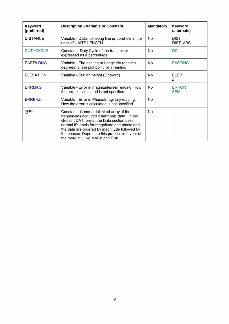
DISTANCE Variable - Distance along line or borehole in theunits of UNITS.LENGTH
No DISTDIST_ABS
DUTYCYCLE Constant - Duty Cycle of the transmitter -expressed as a percentage
No DC
EAST/LONG Variable - The easting or Longitude (decimaldegrees) of the plot point for a reading
No EASTING
ELEVATION Variable - Station height (Z co-ord) No ELEVZ
ERRMAG Variable - Error in magnitude/real reading. Howthe error is calculated is not specified
No ERRORSEM
ERRPHZ Variable - Error in Phase/Imaginary reading.How the error is calculated is not specified
No
@F= Constant - Comma delimited array of thefrequencies acquired if harmonic data. In theGeosoft DAT format the Data section usesnormal IP labels for magnitude and phase andthe data are ordered by magnitude followed bythe phases. Deprecate this practice in favour ofthe more intuitive MAGn and PHn
No
9

Keyword (preferred)
Description - Variable or Constant Mandatory Keyword(alternate)
FREQ Constant or Variable - Instrument channelfrequency - historically used to derive windowtimes. Use of the @Keyword @TIMES,@TIMESSTART, @TIMESEND or use ofCHANNELFILE to derive window times wouldbe preferable as access to historical windowtimes is limited. Not to be confused withTXFREQAvailable instruments and frequencies are:Bison TDEM 2000BISON1 - Time Group 1 Sensitivity 1BISON2 - Time Group 2 Sensitivity 2BISON3 - Time Group 2 Sensitivity 3Crone PEM10 or 10Channel20 or 20Channel30 or 30Channel50 or 50Channel150 or 150ChannelEM3725Hz or HIGH or H6.25Hz or MEDIUM or M2.5Hz or LOW or LGeotem Airborne25Hz or G25 (Geotem Deep)75Hz or G75125Hz or G125Protem2.5Hz or P2.56.25Hz or P6.2525 Hz or P2562.5Hz or P62.5250Hz or P250Questem Airborne37.5Hz or Q37.575Hz or Q75Sirotem MkIISTANDARD or SEARLY or E
No FFREQUENCYBFREQBASEFREQCHANNELS
10

Keyword (preferred)
Description - Variable or Constant Mandatory Keyword(alternate)
FREQ (Cont) Sirotem Mk3STANDARD or S or S3EARLY or E or E3COMPOSITE or C or C3HI-RES or H or H3Zonge GDP-16/3232Hz or Z3216Hz or Z168Hz or Z84Hz or Z42Hz or Z21Hz or Z10.5Hz or Z0.50.25Hz or Z0.250.125Hz or Z0.1250.0625Hz or Z0.0625 Monex TerraTemTI = Intermediate TimesTL= Long TimesTH=High Res TimesTIS = New Intermediate TimesTLS= New Long TimesTHS=New High Res TimesEMIT SMARTemstandard = SMARTem standard timesAll other instrument frequency values areassumed to be user defined. A user definedinstrument can be called by any name notdefined in the list above. For exampleFREQUENCY=U would expect aCHANNELFILE constant to be found, but sowould FREQUENCY=ACME25 or some othermeaningful instrument name not listed.FREQUENCY=USERDEFINED with andaccompanying CHANNELFILE specification isalso acceptable.
GAIN Variable - Gain setting of receiver for thisreading
No G
GPSALT Variable - For airborne Surveys GPS Altitude inmetres relative to ellipsoid
No GPSALTIMITER
INITDELAY Constant or Variable - Time from the start of Txturn off to time zero (in milliseconds). Can bepositive or negative with reference to the top ofthe ramp.
Yes if Timedomainunlesswindowtimes arerelative tothe top ofthe ramp
INITINIT_DELAY
11

Keyword (preferred)
Description - Variable or Constant Mandatory Keyword(alternate)
INSTRUMENT Constant - Instrument Used. Some belowincluded for backward compatibility, for futureuse only use this for self contained instrumentswith built in transmitters. Available include:BISONCRONEDIGEMEM37EM63GDP16 (synonym for ZONGE)GEOTEMHOISTEMMAXMINPOSEMPROTEMQUESTEMQUESTEM450SALTMAPSIROTEM (for Sirotem MkII)SIROTEM3 (for Sirotem Mk3)SPECTREMTEMPESTTERRATEMUTEMZONGE.STINGSWIFTSYSCALLIPPMANN OHMMAPPERFor split systems use with RECEIVER andTRANSMITTER Keywords instead
No INSTTEMINST
KFACT Variable - geometric factor for calculation ofapparent resistivity in galvanic arrays
No
LASALT Variable - Laser altimeter in UNITS.LENGTH No LASERALTIMETER
LINE Constant or Variable - A string containing theline number or hole ID. The line number mayhave a directional suffix e.g. E, N, W, S toindicate the line direction.
Yes BOREHOLEHOLEPROFILE
LOOP Constant or Variable - The EM Loop number forthe data NOT the loop type
No
LOOPSHAPE Constant - the shape of the EM loopOptions IncludeSQUAREDIAMONDRECTANGLECIRCLE
No1
LRADIUS Constant - Tx loop radius in metres - for circularloops
No1
LSIDE Constant - length of a side of the Tx loop No1 LOOPSIDETXSIDE
12

Keyword (preferred)
Description - Variable or Constant Mandatory Keyword(alternate)
LSIDEXLSIDEY
Constant - length of a side of the Tx loop in theX (along line) and Y (across line) direction forrectangular loops, if one used both must be.Use for rectangular moving loops
No1
LVnX Constant - X co-ordinate of the nth Loop vertex No
LVnY Constant - Y co-ordinate of the nth Loop vertex No
LVnZ Constant - Z co-ordinate of the nth Loop vertex No
MAGn Variable - Magnitude of secondary response forFrequency domain survey. Index starting atMAG1 for the fundamental, Harmonics to belabelled incrementally not by the order of theharmonic viz MAG2 = 3rd harmonic
No
MX Variable - User selected chargeability value No IP, CHT
MX_STARTMX_END
Constant - Integration start and end times foruser selected chargeability. Note that currentusage has a space between MX and Start/End -this would no longer be accepted.
No
NBOUND Constant - number of vertices in a boundary. Tobe used only in the Boundary File
Yes ifBoundaryFile used
NORTH/LAT Variable - Northing or Longitude (DecimalDegrees) of plot point for a reading
No NRTHNORTHING
NORTHTYPE Constant - definition of North for AZIMUTH:Options IncludeGRIDMAGNETIC
Yes ifAZIMUTHused
NORMEM Constant - Normalisation type for UTEM orConverted Step Response - OptionsCONTINUOUS, CONTPOINT, PT
No - unlessdata arenormalised
NORMALISATIONNORMALIZATION
NORMPYX Variable or Constant - The X co-ordinate to beused for point primary field normalisation.Primary field normalisation must be set topoint normalisation for this to have any effect.
No - unlessdata arepointnormalised
NORMALISEPTXNORMALIZEPTX
NORMPYY Variable or Constant - The Y co-ordinate to beused for point primary field normalisation.Primary field normalisation must be set topoint normalisation for this to have any effect.
No - unlessdata arepointnormalised
NORMALISEPTYNORMALIZEPTY
NORMPYZ Variable or Constant - The Z co-ordinate to beused for point primary field normalisation.Primary field normalisation must be set topoint normalisation for this to have any effect.
No NORMALISEPTZNORMALIZEPTZ
NORMV Constant - YES/NO flag to indicate primaryvoltage has been current normalised.Discourage voltage normalisation as knowingthe actual current is useful.
No - unlessdata arenormalised
13

Keyword (preferred)
Description - Variable or Constant Mandatory Keyword(alternate)
NSPACE Variable - N level for IP pseudosection plotting No NLEVELN - obsolete
NSTACK Variable - Number of stacks as defined by theequipment manufacturer.
No CYCLEDUR
NSURV Constant - the number of survey points in aSURVEYFILE, only to be used in aSURVEYFILE context
Yes ifSurveyfileused
NULL Constant - A character string representing thenull value used in the data section. This is to beread as a character string to both allow for theGeosoft * and to allow numbers originally storedin double or quad precision to be read intosingle precision arrays. e.g. the IntrepidERMapper null value of -5.0e+75 which is NaNto a 4 byte real input.
No
NUMHOLES Constant - Number of holes in a collar file No
NUMTIMES Constant or Variable - Number of delay times orchannels
No NCHWINDOWS
NVERT Constant - Number of vertices in transmitterwire or loop - only used in WIREFILE
Yes ifwirefileused
OFFTIME Constant - Transmitter off time in mSec Yes if Timedomain
ONTIME Constant - Transmitter on time in mSec Yes if Timedomain
PULSEWIDTH
P1X Variable - X Location of the first potentialelectrode. X can either be station along line ordown hole in which case Y for all electrodes areobtained from the line variable or it can be theeasting (local or UTM) in which case Y must bespecified as a variable
Yes(IP) MX1, P1, M1,M1X, R1X
P1Y Constant or Variable - Y location of the firstpotential electrode. If a constant this could beequivalent to either a line number or a northingfor a remote pole electrode if a variable Yshould be the northing (local or UTM)
Yes (if IP &ARRAY isUSER
MY1, M1Y, R1Y,P1_LINE
P1ZP1D
Constant or Variable - Z location of the firstcurrent electrode where Z is the elevation,increasing upwards upwards If borehole dataand C2D is used D is depth positive down
No M1Z,R1Z
P2X Constant or Variable - X location of the secondpotential electrode. X can either be station alongline or down hole in which case Y for allelectrodes are obtained from the line variable orit can be the easting (local or UTM) in whichcase Y must be specified as a variable
Yes(IP) MX2, P2, M2,M2X, R2X
14
Keyword (preferred)
Description - Variable or Constant Mandatory Keyword(alternate)
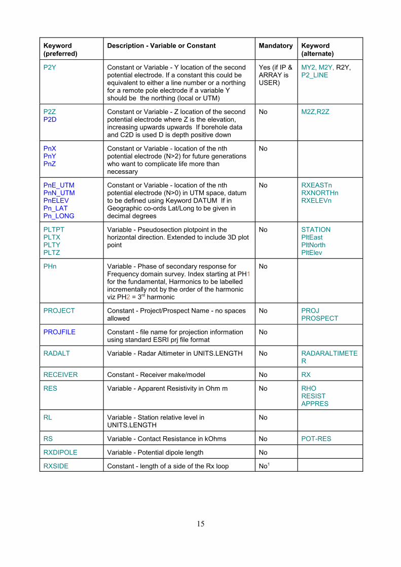
P2Y Constant or Variable - Y location of the secondpotential electrode. If a constant this could beequivalent to either a line number or a northingfor a remote pole electrode if a variable Yshould be the northing (local or UTM)
Yes (if IP &ARRAY isUSER)
MY2, M2Y, R2Y,P2_LINE
P2ZP2D
Constant or Variable - Z location of the secondpotential electrode where Z is the elevation,increasing upwards upwards If borehole dataand C2D is used D is depth positive down
No M2Z,R2Z
PnXPnYPnZ
Constant or Variable - location of the nthpotential electrode (N>2) for future generationswho want to complicate life more thannecessary
No
PnE_UTMPnN_UTMPnELEVPn_LATPn_LONG
Constant or Variable - location of the nthpotential electrode (N>0) in UTM space, datumto be defined using Keyword DATUM If inGeographic co-ords Lat/Long to be given indecimal degrees
No RXEASTnRXNORTHnRXELEVn
PLTPTPLTXPLTYPLTZ
Variable - Pseudosection plotpoint in thehorizontal direction. Extended to include 3D plotpoint
No STATIONPltEast PltNorth PltElev
PHn Variable - Phase of secondary response forFrequency domain survey. Index starting at PH1for the fundamental, Harmonics to be labelledincrementally not by the order of the harmonicviz PH2 = 3rd harmonic
No
PROJECT Constant - Project/Prospect Name - no spacesallowed
No PROJPROSPECT
PROJFILE Constant - file name for projection informationusing standard ESRI prj file format
No
RADALT Variable - Radar Altimeter in UNITS.LENGTH No RADARALTIMETER
RECEIVER Constant - Receiver make/model No RX
RES Variable - Apparent Resistivity in Ohm m No RHORESISTAPPRES
RL Variable - Station relative level inUNITS.LENGTH
No
RS Variable - Contact Resistance in kOhms No POT-RES
RXDIPOLE Variable - Potential dipole length No
RXSIDE Constant - length of a side of the Rx loop No1
15
Keyword (preferred)
Description - Variable or Constant Mandatory Keyword(alternate)
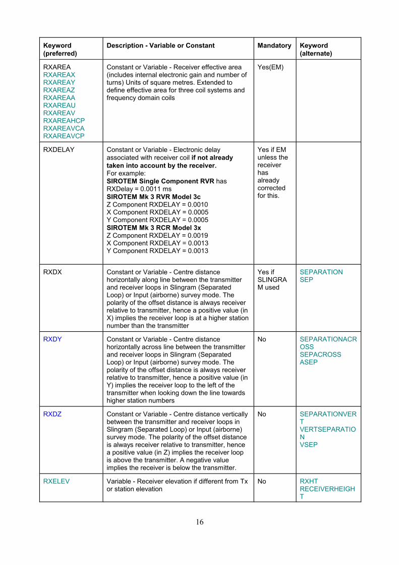
RXAREARXAREAXRXAREAYRXAREAZRXAREAARXAREAURXAREAVRXAREAHCPRXAREAVCARXAREAVCP
Constant or Variable - Receiver effective area(includes internal electronic gain and number ofturns) Units of square metres. Extended todefine effective area for three coil systems andfrequency domain coils
Yes(EM)
RXDELAY Constant or Variable - Electronic delayassociated with receiver coil if not alreadytaken into account by the receiver.For example:SIROTEM Single Component RVR hasRXDelay = 0.0011 msSIROTEM Mk 3 RVR Model 3cZ Component RXDELAY = 0.0010X Component RXDELAY = 0.0005Y Component RXDELAY = 0.0005SIROTEM Mk 3 RCR Model 3xZ Component RXDELAY = 0.0019X Component RXDELAY = 0.0013Y Component RXDELAY = 0.0013
Yes if EMunless thereceiverhasalreadycorrectedfor this.
RXDX Constant or Variable - Centre distancehorizontally along line between the transmitterand receiver loops in Slingram (SeparatedLoop) or Input (airborne) survey mode. Thepolarity of the offset distance is always receiverrelative to transmitter, hence a positive value (inX) implies the receiver loop is at a higher stationnumber than the transmitter
Yes ifSLINGRAM used
SEPARATIONSEP
RXDY Constant or Variable - Centre distancehorizontally across line between the transmitterand receiver loops in Slingram (SeparatedLoop) or Input (airborne) survey mode. Thepolarity of the offset distance is always receiverrelative to transmitter, hence a positive value (inY) implies the receiver loop to the left of thetransmitter when looking down the line towardshigher station numbers
No SEPARATIONACROSS SEPACROSSASEP
RXDZ Constant or Variable - Centre distance verticallybetween the transmitter and receiver loops inSlingram (Separated Loop) or Input (airborne)survey mode. The polarity of the offset distanceis always receiver relative to transmitter, hencea positive value (in Z) implies the receiver loopis above the transmitter. A negative valueimplies the receiver is below the transmitter.
No SEPARATIONVERTVERTSEPARATION VSEP
RXELEV Variable - Receiver elevation if different from Txor station elevation
No RXHTRECEIVERHEIGHT
16
Keyword (preferred)
Description - Variable or Constant Mandatory Keyword(alternate)
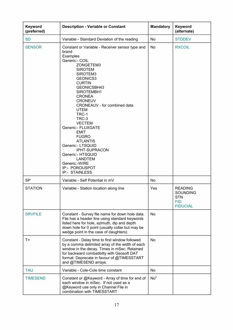
SD Variable - Standard Deviation of the reading No STDDEV
SENSOR Constant or Variable - Receiver sensor type andbrand ExamplesGeneric:- COIL
ZONGETEM3SIROTEMSIROTEM3GEONICS3CURTINGEONICSBH43SIROTEMBH1CRONEACRONEUVCRONEAUV - for combined dataUTEMTRC-1TRC-3VECTEM
Generic:- FLUXGATEEMITFUGROATLANTIS
Generic:- LTSQUIDIPHT-SUPRACON
Generic:- HTSQUIDLANDTEM
Generic:-WIREIP:- POROUSPOTIP:- STAINLESS
No RXCOIL
SP Variable - Self Potential in mV No
STATION Variable - Station location along line Yes READINGSOUNDINGSTNFIDFIDUCIAL
SRVFILE Constant - Survey file name for down hole data.File has a header line using standard keywordslisted here for hole, azimuth, dip and depthdown hole for 0 point (usually collar but may bewedge point in the case of daughters)
No
T= Constant - Delay time to first window followedby a comma delimited array of the width of eachwindow in the decay. Times in mSec. Retainedfor backward combatibilty with Geosoft DATformat. Deprecate in favour of @TIMESSTARTand @TIMESEND arrays.
No
TAU Variable - Cole-Cole time constant No
TIMESEND Constant or @Keyword - Array of time for end ofeach window in mSec. If not used as a@Keyword use only in Channel File incombination with TIMESSTART
No2
17

Keyword (preferred)
Description - Variable or Constant Mandatory Keyword(alternate)
TIMESSTART Constant or @Keyword - Array of time for startof each window in mSec. If not used as a@Keyword use only in Channel File incombination with TIMESEND
No2
TRANSMITTER Constant - Transmitter make/model No TRANSTX
TURNOFF Constant or Variable - Transmitter turn off time(ramp) in mSec
Yes(TimedomainEM)
RAMPRMP
TURNON Constant or Variable - Transmitter turn on timein mSec
No RISETIME
TXAREA Constant or Variable - Transmitter loop area(defined in square metres). If more than oneturn is used, the effective turns moment shouldbe used.
Yes(EM) LOOPAREA
TXCENTX Constant or Variable - Easting (X) coordinatespecification for the centre of an In-Out surveytransmitter loop.
Yes ifusing In-Out
TXCENTY Constant or Variable - Northing (Y) coordinatespecification for the centre of an In-Out surveytransmitter loop.
Yes ifusing In-Out
TXDIPOLE Variable - Current Dipole Length No
TXFREQ Constant or Variable - Transmitter basefrequency
Yes ifFrequencyDomainunless@F= used
TXTURNS Constant or Variable - Number of turns in TxLoop
Yes if EMunless only1 turn orTXAREAspecifiedproperly
TURNS
TXWAVEFORM Constant - descriptor for shape of Tx waveformValid values include :PERIODICRECT or PERIODICSTEP orBIPOLAR : Bipolar waveform.UTEM or PERIODICTRI : Triangular waveform.CRONESTEP : Triangular waveform essentiallythe same as Utem.HALFSINE or HSINE : A bipolar half sinewaveform.AEROTEM : A triangular waveform with offtime.The default value is PERIODICRECT.
No
18

Keyword (preferred)
Description - Variable or Constant Mandatory Keyword(alternate)
UNITS.EMIP Constant - Data units for the EM variable.(μV/A) - microvolts per amp (TEM).(nV/Am2) - nanovolts per amp metre squared (TEM)(ppm) -Parts per million (Airborne TEM)(Ohm-m) - Ohm-metres (resistivity)(S/m) - Siemens per metre (conductivity).MV/V - millivollts per volt (IP)PFE - percentage frequency effect (IP)MRAD - milliradians (FEM/FIP)(μV) - microvolts (TEM)(nT/Sec) - nanoTeslas per second (TEM)(pT/A) - picoTeslas per Amp (TEM)(pT) - picoTeslas (TEM)(nT) - nanoTeslas (TEM)(pV/Am4) - picoVolts per Amp metre4 (TEM)(pVmS/Am4) - picoVolt milliseconds per Ampmetre4 (TEM)nV - nanovoltspV - picovoltsnT - nanoteslapT - picoteslafT - femtoteslappm Hp - parts per million of the primary field inthat componentppt Hp - parts per thousand of the primary fieldin that componentpp2t Hp or pp2000 Hp - parts per two thousandof the primary field in that component -Spectrem uses these unitsppm Ht - parts per million of the total primaryfield at the sensorppt Ht - parts per thousand of the total primaryfield at the sensorppm Hz - parts per million of the primary field inthe Z component at the sensorppt Hz - parts per thousand of the primary fieldin the Z component at the sensorppm Hx - parts per million of the primary field inthe X component at the sensorppt Hx - parts per thousand of the primary fieldin the X component at the sensor%Ht - percentage of the total primary field. Notethat Maxwell used to call this %Hp but theterminology has been changed to bring it in line with the ppmand ppt terms.nT/s - nanotesla per secondpT/s - picotesla per seconduV/m2nVnV/AnV/Am2nV/m2pVpV/ApV/Am2
Yes UNITS
19

Keyword (preferred)
Description - Variable or Constant Mandatory Keyword(alternate)
UNITS.EMIP(cont)
pT/AspT/Asm2nTnT/AnT/Am2nT/m2pTpT/ApT/Am2pT/m2fTfT/AfT/Am2fT/m2
UNITS.LENGTH Constant - Units of distance measurement.M = metresFT = feet
No LENGTH_UNITSUNITS
UNITS.XXXX Constant - for use in mixed datatype files, e.gCSAMT where both E field and H fieldmeasurements need to have their unitsdeclared XXXX is replaced by the keyword forthe variable concerned. Where the Keywordincludes a numeral for its order in the array thisnumeral is dropped. E.g UNITS.PH might definethe units for Phase while UNITS.MAG woulddefine the units for Amplitude. Its use toredefine the units for Current and PrimaryVoltage is discouraged
No
VER Constant used only in Record 1 - Version of thedata transfer format used to allow for futurechanges not being backward compatible (lastresort).
Yes
VP Variable - Primary Voltage in mV Yes(IP) MAG
WAVEFORM Constant - lead to a waveform file describing theTransmitter waveform using TIMES andCURRENTe.g. WAVEFORM:TXWFORM.WFF
No
WIDTH Constant or @Keyword - Array of times forChannel window width (defined in milliseconds).If not used as a @Keyword use only in ChannelFile in combination with DELAY
No2
WIREPATH @Keyword Array of XYZ values describing thepath of the Tx wire The order of vertices shouldbe such that the field in the centre of the loop isup. For a grounded dipole direction is frompositive to negative electrode
No
20

Keyword (preferred)
Description - Variable or Constant Mandatory Keyword(alternate)
WIREFILE Constant - defining name of file containing anarray of XYZ values describing the location ofthe loop. The order of vertices should be suchthat the field in the centre of the loop is up. Fora grounded dipole direction is from positive tonegative electrode
No
XCOLLAR Constant or Variable - X co-ordinate or drill holecollar
No COLE
YCOLLAR Constant or Variable - Y co-ordinate or drill holecollar
No COLN
ZCOLLAR Constant or Variable - Z co-ordinate or drill holecollar
No COLRL
ZONE Constant - UTM Zone if UTM co-ords supplied No
Notes:1 The transmitter loop effective area must be specified as must its shape if not rectangular.The effective area can be specified using a combination of LSIDE or LVnXYZ and NTURNSor directly by TXAREA2 Window times must be specified either using a paired combination of @DELAY and@WIDTH or @TIMESSTART and @TIMESEND as @keywords in the header or by usingtheir non-@ equivalents in the channel file.
Obsolete Keywords for defined Variables and Constants:
The following Keywords are in current usage and may need to be supported for backwardcompatibility but should not be included in the standard.
Keyword (preferred)
Description - Variable or Constant Mandatory Keyword(alternate)
RXLINE Variable - Line for receiver in offset arrays -replace with direct specification of P1X, P1Y,and P2X, P2Y
TIME Constant - Time base of instrument in secondse.g. 2 = 2 second off, 2 second on. Has thepotential to be confused with EM @KeywordTIMES defining the window centre times
No
TXLINE Variable - Line for transmitter in offset arrays -replace with direct specification of C1X, C1Y,and C2X, C2Y
No
/TIMES(ms) Constant - Array of centre times for windows.Time units are defined by the standard, (ms) isthus redundant see TIMES
/TIMESEND(ms) Constant - Array of end times for windows.Time units are defined by the standard, (ms) isthus redundant see TIMESEND
21

Keyword (preferred)
Description - Variable or Constant Mandatory Keyword(alternate)
/TIMESSTART(ms) Constant - Array of start times for windows.Time units are defined by the standard, (ms) isthus redundant see TIMESSTART
UNITS Constant - Distance units.M - metresFT - feetThis clashes with the AMIRA use of theKeyword UNITS which is used to define themeasurement units e.g. mV/V or mRadReplace in both DAT and AMIRA withUNITS.LENGTH (spatial)and UNITS.EMIP(data)
Yes
X Variable - Synonym for EAST. Notrecommended, as confusion may arisebetween X coordinate and X component.
Y Variable - Synonym for NORTH. Notrecommended, as confusion may arisebetween Y coordinate and Y component.
Z Variable - Synonym for ELEV. Notrecommended, as confusion may arisebetween Z coordinate and Z component.
The AMIRA standard allowed for continuation lines designated with an ampersand symbol.This has not been carried through to the new standard.
Unspecified Variables and Constants:
The file may contain any number of other variables or constants which the parsing programmay choose to read or ignore.
Example ESF files:
An example of an older AMIRA type format slightly modified to conform to the new format.Only one window amplitude is shown in the data section.
VER:0001 - TEST DATA FOR TEM DATA FORMAT DATATYPE=TEM UNITS,EMIP=(uV/A) TXAREA=10000 RXAREA=10000 INSTRUMENT=SIROTEM3 RXDELAY=0.001 CONFIG=INLOOPLOOP LINE STATION LSIDE CURRENT TURNOFF GAIN FREQ COMPONENT NUMTIMES VP Ch1 Ch2....cont/SIROTEM Mk3 FIELD DATA/SURVEY AREA :TEST EL 1000/PROSPECT :TEST Test/DATE :31\6\96/CURRENT NORMALIZATION ALTERED FROM VALUE USED BY SIROTEM Mk3= 7.00 TO VALUE ACTUALLY TRANSMITTED = 14.00BHP01 6600N 10940E 100 13 6 .33 0 S Z 18 0 -9.075e+02 ...contBHP01 6600N 10940E 100 13.6 .33 0 S Z 18 0 -9.035e+02BHP01 6600N 10940E 100 13.6 .33 0 E Z 18 0 -1.127e+04BHP01 6600N 10960E 100 13.6 .33 0 S Z 18 0 -1.431e+03BHP01 6600N 10960E 100 13.6 .33 0 S Z 18 0 -1.428e+03BHP01 6600N 10960E 100 13.6 .33 0 S Z 18 0 -1.422e+03BHP01 6600N 10960E 100 13.6 .33 0 E Z 18 0 -1.875e+04BHP01 6600N 10980E 100 13.6 .33 0 S Z 18 0 -3.005e+03BHP01 6600N 10980E 100 13.6 .33 0 S Z 18 0 -3.005e+03BHP01 6600N 10980E 100 13.6 .33 0 E Z 18 0 -2.594e+04BHP01 6600N 10990E 100 13.6 .33 0 S Z 18 0 -2.570e+03
22

BHP01 6600N 10990E 100 13.6 .33 0 S Z 18 0 -2.572e+03
A slightly more complicated example, note that it includes labels not included in the list of recognised keywords. The parsing program canchose to read or ignore these. The data lines have been truncated for simplicity. Note that this is a standard SMARTem V dump file onlyslightly edited to conform to the standard
VER:0001 SMARTem V TEM data file - created Sun May 02 11:39:19 2004LINE:391850 DATATYPE:TEM RECEIVER:SMARTem UNITS,EMIP:(uV/A) CONFIG:INLOOP RXAREA:10000 INITDELAY:0.680 TRANSMITTER:ZT-30 LSIDE:100@TIMESSTART=0.02,0.07,0.13,0.18,0.22,0.32,0.43,0.52,0.62@TIMESEND=0.07,0.13,0.18,0.22,0.32,0.43,0.52,0.62,0.82STATION LOOP RDNG COMPONENT DATETIME OPERATOR FREQ CURRENT SAMP_RATE GAIN NSTACKS TURNOFF INITDELAY NOISE NUMTIMES CH1 CH2 CH3 CH4 CH5 CH6 CH7 CH8 CH9 453000 1 4103 Z 20040503_1311.00 Cam 0.500000 18.400 20000.000 1.0 64 20.0 0.68 0.02 2.167582e+00 44 3.6756e+04 3.6007e+04 3.5230e+04 3.4424e+04 3.3160e+04 ....cont453000 1 4103 Y 20040503_1311.00 Cam 0.500000 18.400 20000.000 4.0 64 20.0 0.68 0.02 3.406500e-01 44 -4.2265e+03 -4.0923e+03 -3.9509e+03 -3.8069e+03 -3.5889e+03 453000 1 4103 X 20040503_1311.00 Cam 0.500000 18.400 20000.000 4.0 64 20.0 0.68 0.02 1.848191e-01 44 -7.4757e+01 -1.4945e+02 -2.2082e+02 -2.8929e+02 -3.8078e+02 453000 1 4104 Z 20040503_1314.00 Cam 0.500000 16.900 20000.000 10.0 64 20.0 0.68 0.02 2.105967e+00 44 2.0590e+04 2.0267e+04 1.9916e+04 1.9538e+04 1.8915e+04 453000 1 4104 Y 20040503_1314.00 Cam 0.500000 16.900 20000.000 10.0 64 20.0 0.68 0.02 3.373084e-01 44 -4.4487e+03 -4.3062e+03 -4.1609e+03 -4.0109e+03 -3.7801e+03 453000 1 4104 X 20040503_1314.00 Cam 0.500000 16.900 20000.000 10.0 64 20.0 0.68 0.02 2.286031e-01 44 -8.4895e+01 -1.6359e+02 -2.3969e+02 -3.1189e+02 -4.0841e+02 453000 1 4105 Z 20040503_1317.00 Cam 0.500000 16.500 20000.000 10.0 64 20.0 0.68 0.02 2.110939e+00 44 2.0945e+04 2.0611e+04 2.0251e+04 1.9862e+04 1.9227e+04 453000 1 4105 Y 20040503_1317.00 Cam 0.500000 16.500 20000.000 10.0 64 20.0 0.68 0.02 3.875816e-01 44 -4.5494e+03 -4.4047e+03 -4.2527e+03 -4.0979e+03 -3.8656e+03 453000 1 4105 X 20040503_1317.00 Cam 0.500000 16.500 20000.000 10.0 64 20.0 0.68 0.02 2.136802e-01 44 -5.0453e+01 -1.3003e+02 -2.0526e+02 -2.7840e+02 -3.7950e+02 453050 1 4100 Z 20040503_1256.00 Cam 0.500000 20.800 20000.000 1.0 64 20.0 0.68 0.02 7.175902e-01 44 3.6858e+04 3.6011e+04 3.5125e+04 3.4205e+04 3.2761e+04 453050 1 4100 Y 20040503_1256.00 Cam 0.500000 20.800 20000.000 4.0 64 20.0 0.68 0.02 4.141825e-01 44 -4.9712e+03 -4.8161e+03 -4.6473e+03 -4.4689e+03 -4.1927e+03 453050 1 4100 X 20040503_1256.00 Cam 0.500000 20.800 20000.000 4.0 64 20.0 0.68 0.02 2.539622e-01 44 1.9840e+03 2.0165e+03 2.0314e+03 2.0315e+03 1.9995e+03 453050 1 4101 Z 20040503_1259.00 Cam 0.500000 19.300 20000.000 10.0 64 20.0 0.68 0.02 6.098337e-01 44 1.9015e+04 1.9015e+04 1.9014e+04 1.9015e+04 1.9015e+04 453050 1 4101 Y 20040503_1259.00 Cam 0.500000 19.300 20000.000 10.0 64 20.0 0.68 0.02 3.779330e-01 44 -5.2024e+03 -5.0394e+03 -4.8642e+03 -4.6791e+03 -4.3880e+03 453050 1 4101 X 20040503_1259.00 Cam 0.500000 19.300 20000.000 10.0 64 20.0 0.68 0.02 2.235410e-01 44 2.0784e+03 2.1129e+03 2.1305e+03 2.1296e+03 2.0963e+03453050 1 4102 Z 20040503_1301.00 Cam 0.500000 18.400 20000.000 10.0 64 20.0 0.68 0.02 5.445768e-01 44 1.9945e+04 1.9946e+04 1.9945e+04 1.9945e+04 1.9945e+04 453050 1 4102 Y 20040503_1301.00 Cam 0.500000 18.400 20000.000 10.0 64 20.0 0.68 0.02 3.798470e-01 44 -5.2438e+03 -5.0782e+03 -4.9001e+03 -4.7126e+03 -4.4205e+03 453100 1 4091 X 20040503_1208.00 Cam 0.500000 21.500 20000.000 4.0 64 20.0 0.68 0.02 2.504953e-01 44 7.4065e+02 6.9924e+02 6.5801e+02 6.1517e+02 5.4861e+02
Here is an example using some IP data, again the data lines have been truncated to fit on this page. Note that this is a standard TQIP outputfile only slightly edited to conform to the standard
VER:0001 IP DATA FROM : 7537500N.mdb (TQIPdb V2.01) 15/05/2010DATATYPE:TDIP LINE:7537500N ARRAY:DPDP DIPOLE:100.0 UNITS.LENGTH:M NUMTIMES:11 INITDELAY:50 Mx_start:590 Mx_end:1450@WIDTH=20,40,40,80,80,140,140,230,230,360,360C1X C2X P1X P2X RxDipole Line PltPt Nlevel SP CURRENT VP RES MX SD Nstack CH1 CH2 CH3 CH4 CH5 CH6 CH7 CH8 CH9 CH10 CH11 600700.0 600900.0 601000.0 601100.0 100.0 7537500 600925.00 1.0 -4.162 28.700 326.7609 17.17 11.72 0.4015 14 54.02299 43.54736 35.80276 29.64072 24.74292 20.74040 17.39645 14.54538 12.07556 600700.0 600900.0 601000.0 601100.0 100.0 7537500 600925.00 1.0 -4.179 25.800 292.6193 17.10 10.95 0.3882 15 54.82899 43.80673 35.72467 29.35610 24.23649 20.05334 16.56073 13.67969 11.28234 600700.0 600900.0 601100.0 601200.0 100.0 7537500 600975.00 2.0 -1.067 28.700 125.8773 23.62 3.78 0.0511 14 22.79920 18.71280 15.27414 12.17962 9.64479 7.60129 6.00451 4.77176 3.86301 3.19372 600700.0 600900.0 601100.0 601200.0 100.0 7537500 600975.00 2.0 -1.086 25.800 112.7033 23.53 4.48 0.2286 15 25.54502 20.77415 16.88750 13.38124 10.56419 8.40590 6.74873 5.47274 4.56066 3.89326
23

A more complete example of a conformable file with three Record type 2 and no Record type 3 - all arrays defined in external files.VER:001 EXAMPLE TEM DATA FILEDATATYPE:TEM BFIELD:No CHANNELFILE:SPECIAL.CON CONFIG:IN_LOOP CONTRACTOR:ACNE_BROTHERS DATUM:GDA94 DUTYCYCLE:50 LOOPSHAPE:RECTANGLE LSIDE:100 NULL:-1.0E30OFFTIME:1000 ONTIME:1000 PROJECT:BIG_MOUNTAIN RECEIVER:SMARTem25 TRANSMITTER:BEAST10000 RXAREA:100000 RXDELAY:0.015 SENSOR:WILLOWBRANCH TXTURNS:1 UNITS.EMIP:uV/A UNITS.LENGTH:M WAVEFORM:SPECIAL.CON ZONE:46STATION LOOP RDNG COMPONENT DATETIME OPERATOR FREQ CURRENT SAMP_RATE GAIN NSTACKS TURNOFF INITDELAY NOISE NUMTIMES CH1 CH2 CH3 CH4 CH5 CH6 CH7 CH8 CH9 453000 1 4103 Z 20040503_1311.00 Cam 0.500000 18.400 20000.000 1.0 64 20.0 0.68 0.02 2.167582e+00 44 3.6756e+04 3.6007e+04 3.5230e+04 3.4424e+04 3.3160e+04 ....cont453000 1 4104 Z 20040503_1314.00 Cam 0.500000 16.900 20000.000 10.0 64 20.0 0.68 0.02 2.105967e+00 44 2.0590e+04 2.0267e+04 1.9916e+04 1.9538e+04 1.8915e+04 453000 1 4105 Z 20040503_1317.00 Cam 0.500000 16.500 20000.000 10.0 64 20.0 0.68 0.02 2.110939e+00 44 2.0945e+04 2.0611e+04 2.0251e+04 1.9862e+04 1.9227e+04
24
Support Files:
The individual support files may be concatenated into a .CON file, the format for which isdescribed at the end of this section. If a concatenated file is used the file names used inRecord type 2 of the ESF file should point to the CON file not the individual components.
Boundary Files
A boundary file describes the outer boundary of the survey. The intention is that this filecan be quickly used to make a polygon for a GIS package for quick indexing. Multiplesurvey boundaries can exist within the one file. The co-ordinates of the boundary shouldbe in decimal degrees. It is not a requirement that the boundary close i.e the last vertexdoes not have to be the same as the first vertex although it may be. Any parsingsoftware that requires a closed polygon will have to check that the first and last pointsare identical and if not add an extra point. Likewise software that automatically closesthe polygon will have to check if the first and last point are identical and remove the lastpoint. The standard allows for both.
The extension should be .BND
The records used to define the instrument time gates are:
Record 1A title describing the boundary name(s)
Record 2The number of vertices in the boundary. Record 2 may be repeated where multipleboundaries are listed.
Record 3Field labels indicating the order of the Longitude and Latitude. Note that if a boundaryis specified using the @BOUNDARY array Keyword the order must be Latitude followedby Longitude. This restriction does not apply to the Boundary File.
Record 4 to End of File or next Record 3Co-ordinates of the vertices of the boundary in decimal degrees in the order specifiedby Record 3
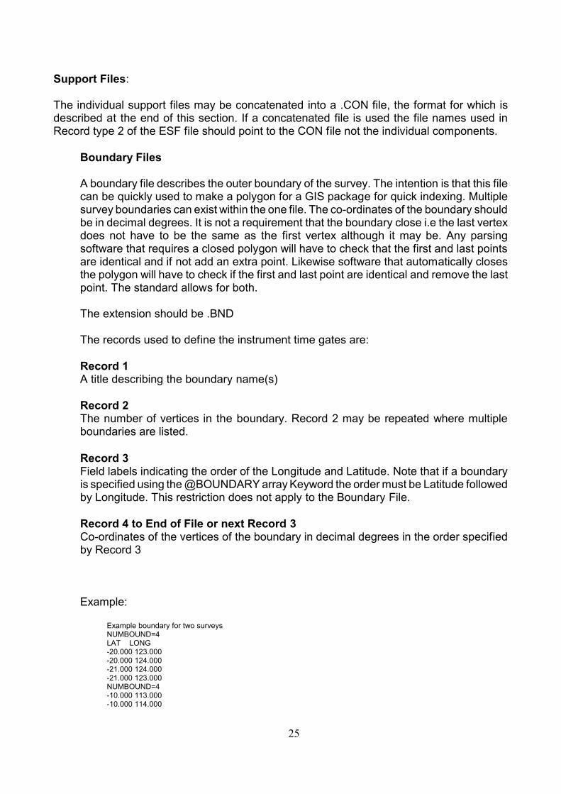
Example:
Example boundary for two surveysNUMBOUND=4LAT LONG-20.000 123.000-20.000 124.000-21.000 124.000-21.000 123.000NUMBOUND=4-10.000 113.000-10.000 114.000
25

-11.000 114.000-11.000 113.000
Channel Files
The channel files are used to define the delay times and widths or start and end timesof the time gates used to acquire the data. The file is comprised of three header recordsfollowed by the individual channel times.
The file extension should be .CHN
The records used to define the instrument time gates are:
Record 1A title describing the instrument name and frequency setting.
Record 2The number of channel ‘gate’ times to follow in the file. Also in most files will be anOfftime parameter. This value is included where the Offtimes and Ontimes of thetransmitter waveform are equal and where it is invariant for the frequency setting. Insome instruments, for example the SIROTEM Mk II and SIROTEM Mk3, the Offtimevaries with the number of channels recorded. In these cases the Offtime parameter isnot included.
Record 3Either the pair DELAY and WIDTH or the pair TIMESSTART and TIMESEND to definethe instrument columns to follow.
Record 4 to End of FileDelay channel times and widths.
Note: The number of channel times and widths as specified must be the same as thevalue of NUMTIMES parameter specified in Record 2 and greater than or equal to thevalue of any NUMTIMES parameter specified in the ESF file. Consequently theNUMTIMES specified in the ESF file may be less than the value specified in the channelfile.
The Delay times listed specify the middle or centre time of the delay time gate. TheWidth parameter spans the Delay time values with half the Width before and after theDelay time.
The Time start and Time end indicate the start and end times for each window or timegate.
All times are specified in milliseconds with respect to time zero.
Two examples of CHANNELFILEs are shown below, both describe identical time gates:
26

UserDefined Instrument - MYINSTR.CHNNUMTIMES:23 OFFTIME:31.25DELAY WIDTH0.09 0.027 0.117 0.027 0.15075 0.0405 0.198 0.0540.25875 0.0675 .... cont
UserDefined Instrument - MYINSTR.CHNNUMTIMES:23 OFFTIME:31.25TIMESSTART TIMESEND0.0765 0.10350.1035 0.13050.1305 0.1710.171 0.2250.225 0.2925.... cont
Collar filesUsed to specify collar co-ordinates for down hole surveys. Use in conjunction with asurvey file. Hole names should match exactly in both files
The file extension should be .COL
The records used to define the deviation are;
Record 1A title describing the collar project name
Record 2The number of holes in the file, NUMHOLESRecord 3The field labels HOLE, EAST, NORTH and ELEVATION to define the collar positionsto follow.
Record 4 to End of FileCo-ordinates for the holes
An example of a COLLARFILE is shown below:
Project X collarsNUMHOLES: 7HOLE EAST NORTH ELEVATION13 345678 7654254 1003.4KDD014 556789 7683479 992.5cont.......
Survey filesUsed to describe the deviation of drill holes for down hole surveys. May be used inconjunction with a collar file.
The file extension should be .SUR
The records used to define the deviation are;
Record 1
27

A title describing the survey name
Record 2The number of survey points in the file, NSURV
Record 3The field labels HOLE, DEPTH, AZIMUTH and DIP or -DIP to define the deviation tofollow.
Record 4 to End of FileSurvey points down the holes. Ordered by top to bottom for each hole
An example of a SURVEYFILE is shown below:
Eastman point SurveysNSURV:134HOLE DEPTH AZIMUTH DIP13 0 127 - 6013 50 120 -63KDD014 10 270 -58KDD014 70 265 -60cont.....
Wire Files
Used to describe the path of the transmitter wire or loop where a simple two or four pointdescription in Record 2 of the ESF file would not suffice
The file extension should be .TXW
The records used to define the wire path are;
Record 1A title describing the wire or loop name
Record 2The number of vertices (NVERT) in the path to follow in the file.
Record 3Either the triplex EAST, NORTH and ELEVATION or the pair EAST and NORTH todefine the vertices to follow.
Record 4 to End of FileVertices of wire or loop. The vertices should be specified in an order from positiveelectrode to negative electrode for dipoles and so that the magnetic field is pointing upin the centre of a loop. In the case of InOut or Double Loops this has no meaning and vertex order is not specified.
An example of a WIREFILE is shown below:
Waste Dump LoopNVERT:213EAST NORTH ELEVATION345672.4 7653287.2 1003.2
28

345652.3 7653283.7 1009.4345635.7 7653295.6 1023.6cont.....
Waveform FileUsed to describe the transmitter waveform
The file extension should be .WFF
The records used to define the transmitter waveform are;
Record 1A title describing the transmitter and waveform
Record 2The number of sample times, NUMTIMES, to follow in the file.
Record 3Either the pair DELAY and CURRENT or the pair DELAY and CH to define thewaveform to follow.
Record 4 to End of FileThe transmitter waveform specified as a series of times and amplitudes of either currentor the secondary field. Remember that the expected units of current are amps,secondary field, the same as specified by UNITS.EMIP
An example of a WAVEFORM file is shown below:
VTEM 25 waveformNVERT:3840DELAY CURRENT0 -9.93364833255039E-090.00520833333333333 -1.44865704849693E-080.0104166666666667 -1.61421785403944E-080.015625 -1.77977865958195E-080.0208333333333333 -6.41548121477213E-080.0260416666666667 -6.43617631546494E-07cont...
Concatenated fileAll the support files above may be appended into a concatenated file. To try andminimise the number of support metadata files which need to travel with the data andthus reduce the chance of one being not copied on a transfer.
The extension of a concatenated file is .CON. If a Concatenated file is used then all thereferences to support files in Record type 2 of the data file header should point to the.CON file.
The records used to define the concatenated file are;
Record 1The keyword for the data type to follow
Record 2 to end of record block
29

Records 1 to 4 of the associated data type.
A blank line may be added between data types for readability but it is not required.
An example of a Concatenated file is shown below:
CHANNELFILEUserDefined Instrument - MYINSTR.CHNNUMTIMES:23 OFFTIME:31.25DELAY WIDTH0.09 0.027 0.117 0.027 0.15075 0.0405 0.198 0.0540.25875 0.0675 .... cont
WAVEFORMVTEM 25 waveformNVERT:3840DELAY CURRENT0 -9.93364833255039E-090.00520833333333333 -1.44865704849693E-080.0104166666666667 -1.61421785403944E-080.015625 -1.77977865958195E-080.0208333333333333 -6.41548121477213E-080.0260416666666667 -6.43617631546494E-07cont...
BOUNDARYExample boundary for two surveysNUMBOUND=4LAT LONG-20.000 123.000-20.000 124.000-21.000 124.000-21.000 123.000
30

Edit History:
30 June, 2013: Clarified Sign convention for UVA components to reference gravity rather thanazimuth to remove ambiguity for up holes. Removed need for TXFREQ to be mandatory if@F used instead. - KF.12 September, 2014: Corrected typo. Removed trailing S from WIDTH in channel file example- KF
31