AUSTRALIA TEST REPORT Berdis Lighting (Zhong Shan) Co ...This report shall not be reproduced except...
24
SHENZHEN LCS COMPLIANCE TESTING LABORATORY LTD. Report No.: LCS1601221768E This report shall not be reproduced except in full, without the written approval of Shenzhen LCS Compliance Testing Laboratory Ltd. Page 1 of 24 AUSTRALIA TEST REPORT For Berdis Lighting (Zhong Shan) Co., LTD. LED Panel Light Model No.: B0401 Prepared for : Berdis Lighting (Zhong Shan) Co., LTD. Address : 6F, No.1, South 2nd Lane, HuaTai East Road, Caosan Industrial Park, Guzhen Town, Zhongshan City, Guangdong Province, China Prepared by : Shenzhen LCS Compliance Testing Laboratory Ltd. Address : 1F., Xingyuan Industrial Park, Tongda Road, Bao’an Avenue., Bao’an District, Shenzhen, Guangdong, China Tel : (+86)755-82591330 Fax : (+86)755-82591332 Web : www.LCS-cert.com Mail : [email protected] Date of receipt of test sample : January 22, 2016 Number of tested samples : 1 Serial number : Prototype Date of Test : January 22, 2016 - February 01, 2016 Date of Report : February 01, 2016
Transcript of AUSTRALIA TEST REPORT Berdis Lighting (Zhong Shan) Co ...This report shall not be reproduced except...

SHENZHEN LCS COMPLIANCE TESTING LABORATORY LTD. Report No.: LCS1601221768E
This report shall not be reproduced except in full, without the written approval of Shenzhen LCS Compliance Testing Laboratory Ltd.
Page 1 of 24
AUSTRALIA TEST REPORT
For
Berdis Lighting (Zhong Shan) Co., LTD.
LED Panel Light
Model No.: B0401
Prepared for : Berdis Lighting (Zhong Shan) Co., LTD.
Address : 6F, No.1, South 2nd Lane, HuaTai East Road, Caosan
Industrial Park, Guzhen Town, Zhongshan City, Guangdong
Province, China
Prepared by : Shenzhen LCS Compliance Testing Laboratory Ltd.
Address : 1F., Xingyuan Industrial Park, Tongda Road, Bao’an Avenue.,
Bao’an District, Shenzhen, Guangdong, China
Tel : (+86)755-82591330
Fax : (+86)755-82591332
Web : www.LCS-cert.com
Mail : [email protected]
Date of receipt of test sample : January 22, 2016
Number of tested samples : 1
Serial number : Prototype
Date of Test : January 22, 2016 - February 01, 2016
Date of Report : February 01, 2016


SHENZHEN LCS COMPLIANCE TESTING LABORATORY LTD. Report No.: LCS1601221768E
This report shall not be reproduced except in full, without the written approval of Shenzhen LCS Compliance Testing Laboratory Ltd.
Page 3 of 24
AUSTRALIA -- TEST REPORT
Test Result according to the standards on page 6: Positive
The test report merely corresponds to the test sample.
It is not permitted to copy extracts of these test result without the written permission of the test
laboratory.
Test Report No. : LCS1601221768E February 01, 2016
Date of issue
Type / Model......................... : B0401
EUT....................................... : LED Panel Light
Applicant.............................. : Berdis Lighting (Zhong Shan) Co., LTD.
Address.................................. : 6F, No.1, South 2nd Lane, HuaTai East Road, Caosan
Industrial Park, Guzhen Town, Zhongshan City, Guangdong
Province, China
Telephone.............................. : /
Fax......................................... : /
Manufacturer....................... : Berdis Lighting (Zhong Shan) Co., LTD.
Address.................................. : 6F, No.1, South 2nd Lane, HuaTai East Road, Caosan
Industrial Park, Guzhen Town, Zhongshan City, Guangdong
Province, China
Telephone.............................. : /
Fax......................................... : /
Factory.................................. : Berdis Lighting (Zhong Shan) Co., LTD. Address.................................. : 6F, No.1, South 2nd Lane, HuaTai East Road, Caosan
Industrial Park, Guzhen Town, Zhongshan City, Guangdong
Province, China
Telephone.............................. : /
Fax......................................... : /

SHENZHEN LCS COMPLIANCE TESTING LABORATORY LTD. Report No.: LCS1601221768E
This report shall not be reproduced except in full, without the written approval of Shenzhen LCS Compliance Testing Laboratory Ltd.
Page 4 of 24
TABLE OF CONTENTS
Test Report Description Page
1. SUMMARY OF STANDARDS AND RESULTS .................................................................... 6
1.1.Description of Standards and Results .................................................................................................. 6
2. GENERAL INFORMATION .................................................................................................... 7
2.1.Description of Device (EUT) ............................................................................................................... 7
2.2.Description of Test Facility ................................................................................................................. 7
2.3.Statement of the measurement uncertainty .......................................................................................... 7
2.4.Measurement Uncertainty .................................................................................................................... 8
3. MEASURING DEVICES AND TEST EQUIPMENT ............................................................ 9
3.1.Conducted Disturbance ........................................................................................................................ 9
3.2.Disturbance Power ............................................................................................................................... 9
3.3.Radiated Electromagnetic Disturbance ................................................................................................ 9
3.4.Radiated Disturbance (Electric Field) ................................................................................................. 9
3.5.Harmonic Current................................................................................................................................. 9
3.6.Voltage fluctuation and Flicker ........................................................................................................... 9
3.7.Electrostatic Discharge ........................................................................................................................ 9
3.8.RF Field Strength Susceptibility ........................................................................................................ 10
3.9.Electrical Fast Transient/Burst ........................................................................................................... 10
3.10.Surge ................................................................................................................................................. 10
3.11.Conducted Susceptibility ................................................................................................................. 10
3.12.Power Frequency Magnetic Field Susceptibility ............................................................................. 10
3.13.Voltage Dips ..................................................................................................................................... 10
3.14.Voltage Short Interruptions ............................................................................................................. 10
4. POWER LINE CONDUCTED MEASUREMENT ............................................................... 11
4.1.Block Diagram of Test Setup ............................................................................................................. 11
4.2.Conducted Power Line Emission Measurement Standard and Limits .............................................. 11
4.3.EUT Configuration on Test ............................................................................................................... 11
4.4.Operating Condition of EUT ............................................................................................................. 11
4.5.Test Procedure .................................................................................................................................... 12
4.6.Test Results ........................................................................................................................................ 12
5. MAGNETIC FIELD EMISSION MEASUREMENT ........................................................... 14
5.1.Block Diagram of Test Setup ............................................................................................................. 14
5.2.Magnetic Field Emission Measurement Standard and Limits........................................................... 14
5.3.EUT Configuration on Test ............................................................................................................... 14
5.4.Operating Condition of EUT ............................................................................................................. 14
5.5.Test Procedure .................................................................................................................................... 15
5.6.Test Results ........................................................................................................................................ 15
6. RADIATED EMISSION MEASUREMENT ......................................................................... 17

SHENZHEN LCS COMPLIANCE TESTING LABORATORY LTD. Report No.: LCS1601221768E
This report shall not be reproduced except in full, without the written approval of Shenzhen LCS Compliance Testing Laboratory Ltd.
Page 5 of 24
6.1.Block Diagram of Test Setup ............................................................................................................. 17
6.2.Test Standard ...................................................................................................................................... 17
6.3.Radiated Emission Limits .................................................................................................................. 17
6.4.EUT Configuration on Test ............................................................................................................... 18
6.5.Operating Condition of EUT ............................................................................................................. 18
6.6.Test Procedure .................................................................................................................................... 18
6.7.Test Results ........................................................................................................................................ 18
7. PHOTOGRAPH ........................................................................................................................ 20
7.1. Photo of Power Line Conducted Measurement ................................................................................ 20
7.2. Photo of Radiated Electromagnetic Disturbance Measurement ....................................................... 20
7.3. Photo of Radiated Measurement ....................................................................................................... 21
8. EXTERNAL AND INTERNAL PHOTOS OF THE EUT .................................................... 22

SHENZHEN LCS COMPLIANCE TESTING LABORATORY LTD. Report No.: LCS1601221768E
This report shall not be reproduced except in full, without the written approval of Shenzhen LCS Compliance Testing Laboratory Ltd.
Page 6 of 24
1. SUMMARY OF STANDARDS AND RESULTS
1.1.Description of Standards and Results
The EUT have been tested according to the applicable standards as referenced below.
EMISSION
Description of Test Item Standard Limits Results
Conducted disturbance
at mains terminals AS/NZS CISPR 15: 2011 -------- PASS
Magnetic field emission AS/NZS CISPR 15: 2011 -------- PASS
Radiated disturbance AS/NZS CISPR 15: 2011 -------- PASS
N/A is an abbreviation for Not Applicable.

SHENZHEN LCS COMPLIANCE TESTING LABORATORY LTD. Report No.: LCS1601221768E
This report shall not be reproduced except in full, without the written approval of Shenzhen LCS Compliance Testing Laboratory Ltd.
Page 7 of 24
2. GENERAL INFORMATION
2.1.Description of Device (EUT)
EUT : LED Panel Light
Model Number : B0401
Power Supply : AC 220V~240V, 50/60Hz, 40W
2.2.Description of Test Facility
Site Description
EMC Lab. : CNAS Registration Number. is L4595. FCC Registration Number. is 899208. Industry Canada Registration Number. is 9642A-1. VCCI Registration Number. is C-4260 and R-3804. ESMD Registration Number. is ARCB0108. UL Registration Number. is 100571-492. TUV SUD Registration Number. is SCN1081. TUV RH Registration Number. is UA 50296516-001
2.3.Statement of the measurement uncertainty
The data and results referenced in this document are true and accurate. The reader is
cautioned that there may be errors within the calibration limits of the equipment and facilities.
The measurement uncertainty was calculated for all measurements listed in this test report acc.
To CISPR 16 – 4 “Specification for radio disturbance and immunity measuring apparatus and
methods – Part 4: Uncertainty in EMC Measurements” and is documented in the LCS quality
system acc. To DIN EN ISO/IEC 17025. Furthermore, component and process variability of
devices similar to that tested may result in additional deviation. The manufacturer has the sole
responsibility of continued compliance of the device.

SHENZHEN LCS COMPLIANCE TESTING LABORATORY LTD. Report No.: LCS1601221768E
This report shall not be reproduced except in full, without the written approval of Shenzhen LCS Compliance Testing Laboratory Ltd.
Page 8 of 24
2.4.Measurement Uncertainty
Test Item Frequency Range Expanded
uncertainty (Ulab)
Expanded
uncertainty (Ucispr)
Conducted Emission (9kHz to 150kHz) 2.63 dB 4.0 dB
(150kHz to 30MHz) 2.35 dB 3.6 dB
Power disturbance (30MHz to 300MHz) 2.90dB 4.5 dB
Electromagnetic
Radiated Emission
(3-loop)
(9kHz to 30MHz) 3.60 dB N/A
Radiated Emission (9kHz to 30MHz) 3.68 dB N/A
Radiated Emission (30MHz to 1000MHz) 3.48 dB 5.2 dB
Radiated Emission (above 1000MHz) 3.90 dB N/A
Mains Harmonic Voltage 0.510% N/A
Voltage Fluctuations
& Flicker Voltage 0.510% N/A
(1) Where relevant, the following measurement uncertainty levels have been estimated for tests
performed on the apparatus.
(2) The reported expanded uncertainty of measurement is stated as the standard uncertainty of
measurement multiplied by the coverage factor of k=2, which for a normal distribution
corresponds to a coverage probability of approximately 95%.

SHENZHEN LCS COMPLIANCE TESTING LABORATORY LTD. Report No.: LCS1601221768E
This report shall not be reproduced except in full, without the written approval of Shenzhen LCS Compliance Testing Laboratory Ltd.
Page 9 of 24
3. MEASURING DEVICES AND TEST EQUIPMENT
3.1.Conducted Disturbance
Item Test Equipment Manufacturer Model No. Serial No. Last Cal.
1 EMI Test Receiver ROHDE & SCHWARZ ESCI 101142 2015/06/18
2 10dB Attenuator SCHWARZBECK OSPAM236 9729 2015/06/18
3 Artificial Mains ROHDE & SCHWARZ ENV216 101288 2015/06/18
4 EMI Test Software AUDIX E3 N/A 2015/06/18
3.2.Disturbance Power
Item Test Equipment Manufacturer Model No. Serial No. Last Cal.
1 EMI Test Receiver ROHDE & SCHWARZ ESCI 101142 2015/06/18
2 Absorbing clamp ROHDE & SCHWARZ MDS 21 4033 2014/10/28
3 EMI Test Software AUDIX E3 N/A 2015/06/18
3.3.Radiated Electromagnetic Disturbance
Item Test Equipment Manufacturer Model No. Serial No. Last Cal.
1 EMI Test Receiver ROHDE & SCHWARZ ESCI 1011423 2015/06/18
2 Triple-loop Antenna EVERFINE LLA-2 11050003 2015/06/18
3 EMI Test Receiver ROHDE & SCHWARZ ESPI 101840 2015/06/18
4 EMI Test Software AUDIX E3 N/A 2015/06/18
3.4.Radiated Disturbance (Electric Field)
Item Test Equipment Manufacturer Model No. Serial No. Last Cal.
1 3m Semi Anechoic Chamber SIDT FRANKONIA SAC-3M 03CH03-HY 2015/02/04
2 EMI Test Receiver ROHDE & SCHWARZ ESPI 101840 2015/06/18
3 Log per Antenna SCHWARZBECK VULB9163 9163-470 2015/06/18
4 EMI Test Software AUDIX E3 N/A 2015/06/18
5 Positioning Controller MF MF-7082 / 2015/06/18
3.5.Harmonic Current
Item Test Equipment Manufacturer Model No. Serial No. Last Cal.
1 Power Analyzer Test System Voltech PM6000 20000670053 2015/06/18
3.6.Voltage fluctuation and Flicker
Item Test Equipment Manufacturer Model No. Serial No. Last Cal.
1 Power Analyzer Test System Voltech PM6000 20000670053 2015/06/18
3.7.Electrostatic Discharge
Item Test Equipment Manufacturer Model No. Serial No. Last Cal.
1 ESD Simulator KIKUSUI KC001311 KES4021 2015/09/02

SHENZHEN LCS COMPLIANCE TESTING LABORATORY LTD. Report No.: LCS1601221768E
This report shall not be reproduced except in full, without the written approval of Shenzhen LCS Compliance Testing Laboratory Ltd.
Page 10 of 24
3.8.RF Field Strength Susceptibility
Item Test Equipment Manufacturer Model No. Serial No. Last Cal.
1 SIGNAL GENERATOR HP 8648A 625U00573 2015/06/18
2 Amplifier AR 500A100 17034 2015/06/18
3 Amplifier AR 100W/1000M1 17028 2015/06/18
4 Isotropic Field Monitor AR FM2000 16829 2015/06/18
5 Isotropic Field Probe AR FP2000 16755 2015/06/18
6 Bi-conic Antenna EMCO 3108 9507-2534 2015/06/18
7 By-log-periodic Antenna AR AT1080 16812 2015/06/18
8 EMS Test Software ROHDE & SCHWARZ ESK1 N/A 2015/06/18
3.9.Electrical Fast Transient/Burst
Item Test Equipment Manufacturer Model No. Serial No. Last Cal.
1 Electrical fast
transient(EFT)generator 3CTEST EFT-4021 EC0461044 2016/01/20
2 Coupling Clamp 3CTEST EFTC EC0441098 2015/06/18
3.10.Surge
Item Test Equipment Manufacturer Model No. Serial No. Last Cal.
1 Surge test system 3CTEST SG5006G EC5581070 2015/06/18
2 Coupling/decoupling
network 3CTEST SGN-5010G CS5591033 2015/06/18
3.11.Conducted Susceptibility Item Test Equipment Manufacturer Model No. Serial No. Last Cal.
1 Simulator EMTEST CWS500C 0900-12 2015/06/18
2 CDN EMTEST CDN-M2 5100100100 2015/06/18
3 CDN EMTEST CDN-M3 0900-11 2015/06/18
4 CDN EMTEST CDN-M 0900-12 2015/06/18
5 Attenuator EMTEST ATT6 0010222A 2015/06/18
6 Infuse tongs EMTEST EM-Clamp 0513A031201 2015/06/18
3.12.Power Frequency Magnetic Field Susceptibility
Item Test Equipment Manufacturer Model No. Serial No. Last Cal.
1
Power frequency
mag-field generator
System
EVERFINE EMS61000-8K 906003 2015/06/18
3.13.Voltage Dips
Item Test Equipment Manufacturer Model No. Serial No. Last Cal.
1 Voltage dips and up
generator 3CTEST VDG-1105G EC0171014 2015/06/18
3.14.Voltage Short Interruptions
Item Test Equipment Manufacturer Model No. Serial No. Last Cal.
1 Voltage dips and up
generator 3CTEST VDG-1105G EC0171014 2015/06/18

SHENZHEN LCS COMPLIANCE TESTING LABORATORY LTD. Report No.: LCS1601221768E
This report shall not be reproduced except in full, without the written approval of Shenzhen LCS Compliance Testing Laboratory Ltd.
Page 11 of 24
4. POWER LINE CONDUCTED MEASUREMENT
4.1.Block Diagram of Test Setup
4.2.Conducted Power Line Emission Measurement Standard and Limits
4.2.1.Standard:
AS/NZS CISPR 15: 2011
4.2.2.Limits
Frequency At mains terminals (dBµV)
Quasi-peak Level Average Level
9kHz ~ 50kHz 110 --
50kHz ~ 150kHz 90 ~ 80* --
150kHz ~ 0.5MHz 66 ~ 56* 56 ~ 46*
0.5MHz ~ 5MHz 56 46
5.0MHz ~ 30MHz 60 50
1. At the transition frequency the lower limit applies.
2. * decreasing linearly with logarithm of the frequency.
4.3.EUT Configuration on Test
The configuration of the EUT is same as Section 2.1.
4.4.Operating Condition of EUT
4.4.1.Setup the EUT as shown in Section 4.1.
4.4.2.Turn on the power of all equipments.
4.4.3.Let the EUT work in test mode (On) and measure it.
Ground
EUT
LISN
Receiver

SHENZHEN LCS COMPLIANCE TESTING LABORATORY LTD. Report No.: LCS1601221768E
This report shall not be reproduced except in full, without the written approval of Shenzhen LCS Compliance Testing Laboratory Ltd.
Page 12 of 24
4.5.Test Procedure
The EUT is put on the table which is 0.8 meter high above the ground and connected to the
AC mains through a Line Impedance Stabilization Network (L.I.S.N.). This provided a
50ohm coupling impedance for the tested equipments. Both sides of AC line are checked to
find out the maximum conducted emission according to the CISPR 15 regulations during
conducted emission measurement. And the voltage probe had been used for the load terminals
measurement according to the CISPR 15 standard.
The bandwidth of the test receiver is set at 200Hz in 9k~150kHz range and 9kHz in
150k~30MHz range.
The frequency range from 9kHz to 30MHz is checked.
All the test results are listed in Section 4.6.
The frequency range from 9kHz to 30MHz is investigated.
4.6.Test Results
PASS.
All the scanning waveform is in next page.

SHENZHEN LCS COMPLIANCE TESTING LABORATORY LTD. Report No.: LCS1601221768E
This report shall not be reproduced except in full, without the written approval of Shenzhen LCS Compliance Testing Laboratory Ltd.
Page 13 of 24
Model No. B0401 Test Mode ON
Environmental Conditions 24℃, 56% RH Test Engineer Davey Xu
Pol Line
Model No. B0401 Test Mode ON
Environmental Conditions 24℃, 56% RH Test Engineer Davey Xu
Pol Neutral

SHENZHEN LCS COMPLIANCE TESTING LABORATORY LTD. Report No.: LCS1601221768E
This report shall not be reproduced except in full, without the written approval of Shenzhen LCS Compliance Testing Laboratory Ltd.
Page 14 of 24
5. MAGNETIC FIELD EMISSION MEASUREMENT
5.1.Block Diagram of Test Setup
AC Mains
Ground Plane
5.2.Magnetic Field Emission Measurement Standard and Limits
5.2.1.Test Standard
AS/NZS CISPR 15: 2011
5.2.2.Test Limits
Frequency Limits for loop diameter (dBµA)
2m
9kHz ~ 70kHz 88
70kHz ~ 150kHz 88 ~ 58*
150kHz ~ 3.0MHz 58 ~ 22*
3.0MHz ~ 30MHz 22
1.At the transition frequency the lower limit applies.
2.* decreasing linearly with logarithm of the frequency.
5.3.EUT Configuration on Test
The configuration of the EUT is same as Section 2.1.
5.4.Operating Condition of EUT
Same as conducted measurement which is listed in Section 4.4, except the test set up replaced
by Section 5.1.
EUT
2m Loop Antenna
Test Receiver

SHENZHEN LCS COMPLIANCE TESTING LABORATORY LTD. Report No.: LCS1601221768E
This report shall not be reproduced except in full, without the written approval of Shenzhen LCS Compliance Testing Laboratory Ltd.
Page 15 of 24
5.5.Test Procedure
The EUT is placed on a wood table in the center of a loop antenna. The induced
current in the loop antenna is measured by means of a current probe and the test receiver.
Three field components are checked by means of a coaxial switch.
The frequency range from 9kHz to 30MHz is investigated. The receiver is measured with the
quasi-peak detector. For frequency band 9kHz to 150kHz, the bandwidth of the field strength
meter is set at 200Hz. For frequency band 150kHz to 30MHz, the bandwidth is set at 9kHz.
All the test results are listed in Section 5.6.
5.6.Test Results
PASS.
The frequency range from 9kHz to 30MHz is investigated.
Model No. B0401 Test Mode ON
Environmental Conditions 24℃, 56% RH Test Engineer Davey Xu
Pol X

SHENZHEN LCS COMPLIANCE TESTING LABORATORY LTD. Report No.: LCS1601221768E
This report shall not be reproduced except in full, without the written approval of Shenzhen LCS Compliance Testing Laboratory Ltd.
Page 16 of 24
Model No. B0401 Test Mode ON
Environmental Conditions 24℃, 56% RH Test Engineer Davey Xu
Pol Y
Model No. B0401 Test Mode ON
Environmental Conditions 24℃, 56% RH Test Engineer Davey Xu
Pol Z
SHENZHEN LCS COMPLIANCE TESTING LABORATORY LTD. Report No.: LCS1601221768E
This report shall not be reproduced except in full, without the written approval of Shenzhen LCS Compliance Testing Laboratory Ltd.
Page 17 of 24
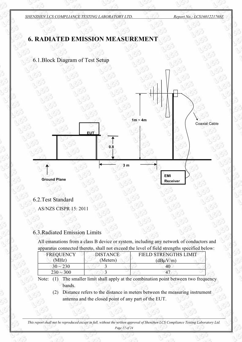
6. RADIATED EMISSION MEASUREMENT
6.1.Block Diagram of Test Setup
6.2.Test Standard
AS/NZS CISPR 15: 2011
6.3.Radiated Emission Limits
All emanations from a class B device or system, including any network of conductors and
apparatus connected thereto, shall not exceed the level of field strengths specified below:
FREQUENCY DISTANCE FIELD STRENGTHS LIMIT
(MHz) (Meters) (dBµV/m)
30 ~ 230 3 40
230 ~ 300 3 47
Note: (1) The smaller limit shall apply at the combination point between two frequency
bands.
(2) Distance refers to the distance in meters between the measuring instrument
antenna and the closed point of any part of the EUT.
1m ~ 4m
Ground Plane
0.8
EUT
EMI
Receiver
Coaxial Cable
3 m

SHENZHEN LCS COMPLIANCE TESTING LABORATORY LTD. Report No.: LCS1601221768E
This report shall not be reproduced except in full, without the written approval of Shenzhen LCS Compliance Testing Laboratory Ltd.
Page 18 of 24
6.4.EUT Configuration on Test
The CISPR 15 regulations test method must be used to find the maximum emission during
radiated emission measurement.
6.5.Operating Condition of EUT
6.5.1 Turn on the power.
6.5.2 After that, let the EUT work in test mode (ON) and measure it.
6.6.Test Procedure
The EUT is placed on a turntable, which is 0.8 meter high above the ground. The turntable
can rotate 360 degrees to determine the position of the maximum emission level. The EUT is
set 3 meters away from the receiving antenna, which is mounted on an antenna tower. The
antenna can be moved up and down from 1 to 4 meters to find out the maximum emission
level. By-log antenna (calibrated by Dipole Antenna) is used as a receiving antenna. Both
horizontal and vertical polarization of the antenna is set on test.
The bandwidth of the Receiver is set at 120kHz.
The frequency range from 30MHz to 300MHz is investigated.
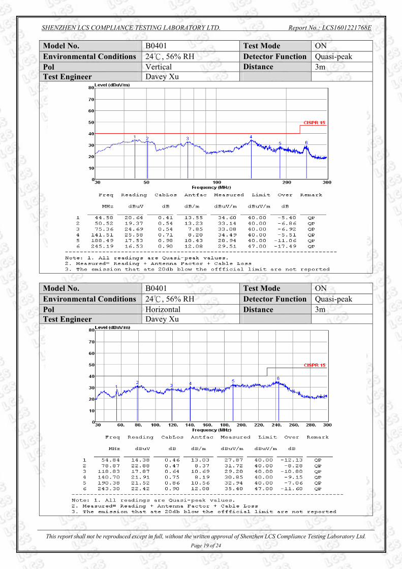
6.7.Test Results
PASS.
All the scanning waveform is in next page.
SHENZHEN LCS COMPLIANCE TESTING LABORATORY LTD. Report No.: LCS1601221768E
This report shall not be reproduced except in full, without the written approval of Shenzhen LCS Compliance Testing Laboratory Ltd.
Page 19 of 24
Model No. B0401 Test Mode ON
Environmental Conditions 24℃, 56% RH Detector Function Quasi-peak
Pol Vertical Distance 3m
Test Engineer Davey Xu
Model No. B0401 Test Mode ON
Environmental Conditions 24℃, 56% RH Detector Function Quasi-peak
Pol Horizontal Distance 3m
Test Engineer Davey Xu

SHENZHEN LCS COMPLIANCE TESTING LABORATORY LTD. Report No.: LCS1601221768E
This report shall not be reproduced except in full, without the written approval of Shenzhen LCS Compliance Testing Laboratory Ltd.
Page 20 of 24
7. PHOTOGRAPH
7.1. Photo of Power Line Conducted Measurement
7.2. Photo of Radiated Electromagnetic Disturbance Measurement

SHENZHEN LCS COMPLIANCE TESTING LABORATORY LTD. Report No.: LCS1601221768E
This report shall not be reproduced except in full, without the written approval of Shenzhen LCS Compliance Testing Laboratory Ltd.
Page 21 of 24
7.3. Photo of Radiated Measurement

SHENZHEN LCS COMPLIANCE TESTING LABORATORY LTD. Report No.: LCS1601221768E
This report shall not be reproduced except in full, without the written approval of Shenzhen LCS Compliance Testing Laboratory Ltd.
Page 22 of 24
8. EXTERNAL AND INTERNAL PHOTOS OF THE EUT
Fig. 1
Fig. 2

SHENZHEN LCS COMPLIANCE TESTING LABORATORY LTD. Report No.: LCS1601221768E
This report shall not be reproduced except in full, without the written approval of Shenzhen LCS Compliance Testing Laboratory Ltd.
Page 23 of 24
Fig. 3
Fig. 4

SHENZHEN LCS COMPLIANCE TESTING LABORATORY LTD. Report No.: LCS1601221768E
This report shall not be reproduced except in full, without the written approval of Shenzhen LCS Compliance Testing Laboratory Ltd.
Page 24 of 24
Fig. 5
Fig. 6
----------------- THE END OF TEST REPORT -------------