August 2, 1993
99
3 0 UNITED STATES NUCLEAR REGULATORY COMMISSION WASHINGTON, D. C. 20555 August 2, 1993 Docket Nos. 50-277 and 50-278 Mr. George A. Hunger, Jr. Director-Licensing, MC 52A-5 Philadelphia Electric Company Nuclear Group Headquarters Correspondence Control Desk P.O. Box No. 195 Wayne, Pennsylvania 19087-0195 Dear Mr. Hunger: SUBJECT: EXTENSION OF TECHNICAL SPECIFICATION SURVEILLANCE INTERVALS TO 24 MONTHS, PEACH BOTTOM ATOMIC POWER STATION, UNIT NOS. 2 AND 3 (TAC NOS. M83704 AND M83705) The Commission has issued the enclosed Amendments Nos. 179 and 182 to Facility Operating License Nos. DPR-44 and DPR-56 for the Peach Bottom Atomic Power Station, Unit Nos. 2 and 3. These amendments consist of changes to the Technical Specifications (TSs) in response to your applications dated September 28, 1992 and October 19, 1992. Additional information was provided in letters dated March 16, 1993, April 13, 1993, May 28, 1993, June 7, 1993, June 23, 1993, July 1, 1993 and July 7, 1993. These supplemental letters provided clarifying information that did not change the initial proposed no significant hazards consideration determination. These amendments extend the interval for certain Technical Specification surveillance requirements to 24 months with an additional 25-percent grace period. The extension of the interval is accomplished for some surveillances by explicitly embedding the term 24 months in the particular line item requirement. For other surveillances, the extension is accomplished by changing the TS Section 1.0 definition of operating cycle or refueling cycle to a maximum of 732 days. A 25-percent grace period beyond the 732 days is allowed. For some surveillances, the licensee stated that it was not possible to demonstrate the acceptability of extending the surveillance interval beyond 18 months (plus a 25% grace period). For some of these surveillances, the wording of the specific TS has been revised in such a way that the actual surveillance interval remains unchanged. You are requested to notify the staff when you have fully implemented the provisions of these amendments. NRC FILE CENTER COPY 930B240306 930802 iNI PDR ADOCK 05000277 P PDR
Transcript of August 2, 1993

3 0 UNITED STATES
NUCLEAR REGULATORY COMMISSION WASHINGTON, D. C. 20555
August 2, 1993
Docket Nos. 50-277 and 50-278
Mr. George A. Hunger, Jr. Director-Licensing, MC 52A-5 Philadelphia Electric Company Nuclear Group Headquarters Correspondence Control Desk P.O. Box No. 195 Wayne, Pennsylvania 19087-0195
Dear Mr. Hunger:
SUBJECT: EXTENSION OF TECHNICAL SPECIFICATION SURVEILLANCE INTERVALS TO 24 MONTHS, PEACH BOTTOM ATOMIC POWER STATION, UNIT NOS. 2 AND 3 (TAC NOS. M83704 AND M83705)
The Commission has issued the enclosed Amendments Nos. 179 and 182 to Facility Operating License Nos. DPR-44 and DPR-56 for the Peach Bottom Atomic Power Station, Unit Nos. 2 and 3. These amendments consist of changes to the Technical Specifications (TSs) in response to your applications dated September 28, 1992 and October 19, 1992. Additional information was provided in letters dated March 16, 1993, April 13, 1993, May 28, 1993, June 7, 1993, June 23, 1993, July 1, 1993 and July 7, 1993. These supplemental letters provided clarifying information that did not change the initial proposed no significant hazards consideration determination.
These amendments extend the interval for certain Technical Specification surveillance requirements to 24 months with an additional 25-percent grace period. The extension of the interval is accomplished for some surveillances by explicitly embedding the term 24 months in the particular line item requirement. For other surveillances, the extension is accomplished by changing the TS Section 1.0 definition of operating cycle or refueling cycle to a maximum of 732 days. A 25-percent grace period beyond the 732 days is allowed.
For some surveillances, the licensee stated that it was not possible to demonstrate the acceptability of extending the surveillance interval beyond 18 months (plus a 25% grace period). For some of these surveillances, the wording of the specific TS has been revised in such a way that the actual surveillance interval remains unchanged.
You are requested to notify the staff when you have fully implemented the provisions of these amendments.
NRC FILE CENTER COPY 930B240306 930802 iNI PDR ADOCK 05000277 P PDR

Mr. George A. Hunger, Jr.
A copy of the Safety Evaluation is also enclosed. Notice of Issuance will be included in the Commission's Bi-Weekly Federal Register Notice.
Sincerely,
/S/
Joseph W. Shea, Project Manager Project Directorate 1-2 Division of Reactor Projects - I/II Office of Nuclear Reactor Regulation
Enclosures: 1. Amendment No. 179 to DPR-44 2. Amendment No. 182 to DPR-56 3. Safety Evaluation
cc w/enclosures: See next page DISTRIBUTION: Docket File NRC & Local PDRs PDI-2 Reading SVarga JCalvo CMiller MO'Brien(2) JShea/FRinaldi *PprvinII• Cnncurrence
OGC DHagan, 3206 GHill(4) Wanda Jones CGrimes, 11E21 RJones ACRS(10) OPA /
OC/LFDCB JNorberg CMcCraeken CBerlinger RBarrdtt JWermiel EWenzinger, RGN-I JWhite, RGN-I
OFFICE PD 1~ PDI/'2, PNC- PDI-2/Dh EMEB* SPLB*
NAME MO' JS CMiller JNorberg CMcCracken
DATE U ,9~(93_ /-1i193 'r/VT93 07/13/93 06/21/93
OFFICE EELB* SCSB* SRXB* HICB* OTSB*
NAME CBerlinger RBarrett RJones JWermiel CGrimes
DATE 07/07/93 06/22/93 06/14/93 07/15/93 07/22/93
OFFICE OGC • __ _ __ _ _
NAME U_. S. 't
DATE - _7 93
*Peiu ..... oncurrencerl~u.^. nO'/A
OFFICIAL KREUKU COPY
100135
August 2, 1993-2 -
rLLtNMMt: A:\rD0J1V4.
Mr. George A. Hunger, Jr. -2- August 2, 1993
A copy of the Safety Evaluation is also enclosed. Notice of Issuance will be included in the Commission's Bi-Weekly Federal Register Notice.
Sincerely,
/S/
Joseph W. Shea, Project Manager Project Directorate 1-2 Division of Reactor Projects - I/II Office of Nuclear Reactor Regulation
Enclosures: 1. Amendment No. 179 2. Amendment No. 182 3. Safety Evaluation
cc w/enclosures: See next page DISTRIBUTION: Docket File NRC & Local PDRs PDI-2 Reading SVarga JCalvo CMiller MO'Brien(2) JShea/FRinaldi *Previous Concurrence
to DPR-44 to DPR-56
OGC DHagan, 3206 GHill(4) Wanda Jones CGrimes, 11E21 RJones ACRS(10) OPA
OC/LFDCB JNorberg CMcCracken CBerlinger RBarrett JWermiel EWenzinger, RGN-I JWhite, RGN-I
OFFICE PDI-Zj -I PD I2PN " PDI-2/D•b EMEB* SPLB*
NAME MO JS is CMiller JNorberg CMcCracken
DATE /93 k193 1 07/13/93 06/21/93
OFFICE EELB* SCSB* SRXB* HICB* OTSB*
NAME CBerlinger RBarrett RJones JWermiel CGrimes
DATE 07/07/93 06/22/93 06/14/93 07/15/93 07/22/93
OFFICE OGC C _ _ ___ _
•AME ,. L o• 9, e C "
DATE 7/,• 7/93 .
OFFICIAL RCOUKU CUPY
W4 -
PtIUNA•t: A:\rUU$/U4.AMU

Mr. George A. Hunger, Jr.
A copy of the Safety Evaluation is also enclosed. Notice of Issuance will be included in the Commission's Bi-Weekly Federal Register Notice.
S i rnc Y
)
J se hW. Shea, Project Manager Project Directorate 1-2 Division of Reactor Projects - I/II Office of Nuclear Reactor Regulation
Enclosures: 1. Amendment No. 179 2. Amendment No. 182 3. Safety Evaluation
to DPR-44 to DPR-56
cc w/enclosures: See next page
-2 - August 2, 1993

Mr. George A. Hunger, Jr. Philadelphia Electric Company
Peach Bottom Atomic Power Station, Units 2 and 3
cc:
J. W. Durham, Sr., Esquire Sr. V.P. & General Counsel Philadelphia Electric Company 2301 Market Street, S26-1 Philadelphia, Pennsylvania 19101
Philadelphia Electric Company ATTN: Mr. D. B. Miller, Vice President Peach Bottom Atomic Power Station Route 1, Box 208 Delta, Pennsylvania 17314
Philadelphia Electric Company ATTN: Regulatory Engineer, AI-2S Peach Bottom Atomic Power Station Route 1, Box 208 Delta, Pennsylvania 17314
Resident Inspector U.S. Nuclear Regulatory Commission Peach Bottom Atomic Power Station P.O. Box 399 Delta, Pennsylvania 17314
Regional Administrator, Region I U.S. Nuclear Regulatory Commission 475 Allendale Road King of Prussia, Pennsylvania 19406
Mr. Roland Fletcher Department of Environment 201 West Preston StreetBaltimore, Maryland 21201
Carl D. Schaefer External Operations - Nuclear Delmarva Power & Light Company P.O. Box 231 Wilmington, DE 19899
Mr. William P. Dornsife, Director Bureau of Radiation Protection Pennsylvania Department of
Environmental Resources P. 0. Box 2063 Harrisburg, Pennsylvania 17120
Board of Supervisors Peach Bottom Township R. D. #1 Delta, Pennsylvania 17314
Public Service Commission Engineering Division ATTN: Chief Engineer 231 E. Baltimore Street Baltimore, MD 21202-3486
of Maryland
Mr. Richard McLean Power Plant and Environmental
Review Division Department of Natural Resources B-3, Tawes States Office Building Annapolis, Maryland 21401
UNITED STATES NUCLEAR REGULATORY COMMISSION
WASHINGTON, D. C. 20555
PHILADELPHIA ELECTRIC COMPANY
PUBLIC SERVICE ELECTRIC AND GAS COMPANY
DELMARVA POWER AND LIGHT COMPANY
ATLANTIC CITY ELECTRIC COMPANY
DOCKET NO. 50-277
PEACH BOTTOM ATOMIC POWER STATION, UNIT NO. 2
AMENDMENT TO FACILITY OPERATING LICENSE
Amendment No. 179 License No. DPR-44
1. The Nuclear Regulatory Commission (the Commission) has found that:
A. The application for amendment by Philadelphia Electric Company, et. al. (the licensee) dated September 28, 1992 and October 19, 1992, as supplemented by letters dated March 16, 1993, April 13, 1993, May 28, 1993, June 7, 1993, June 23, 1993, July 1, 1993 and July 7, 1993, complies with the standards and requirements of the Atomic Energy Act of 1954, as amended (the Act), and the Commission's rules and regulations set forth in 10 CFR Chapter I.
B. The facility will operate in conformity with the application, the provisions of the Act, and the rules and regulations of the Commission;
C. There is reasonable assurance (i) that the activities authorized by this amendment can be conducted without endangering the health and safety of the public, and (ii) that such activities will be conducted in compliance with the Commission's regulations;
D. The issuance of this amendment will not be inimical to the common defense and security or to the health or safety of the public; and
E. The issuance of this amendment is in accordance with 10 CFR Part 51 of the Commission's regulations and all applicable requirements have been satisfied.
2. Accordingly, the license is amended by changes to the Technical Specifications as indicated in the attachment to this license amendment, and paragraph 2.C(2) of Facility Operating License No. DPR-44 is hereby amended to read as follows:
9308240315 930802 PDR ADOCK 05000277 P PDR

-2-
(2) Technical Specifications
The Technical Specifications contained in Appendices A and B, as revised through Amendment No. 179 , are hereby incorporated in the license. PECO shall operate the facility in accordance with the Technical Specifications.
3. This license amendment is effective as of August 2, 1993.
FOR THE NUCLEAR REGULATORY COMMISSION
Michael L. Director Project Directorate 1-2 Division of Reactor Projects - I/II Office of Nuclear Reactor Regulation
Attachment: Changes to the Technical
Specifications
Date of Issuance: Au~ist 2, 1993

ATTACHMENT TO LICENSE AMENDMENT NO.179
FACILITY OPERATING LICENSE NO. DPR-44
DOCKET NO. 50-277
Replace the following pages of the Appendix A Technical Specifications with the enclosed pages. The revised areas are indicated by marginal lines.
Remove Insert
5 5
6 6
8 8
44 44
81a 81a
86a 86a
157 157
169 169
170 170
178 178
188 188
193 193
211 211
217 217
218d 218d
218e 218e
218f 218f
218h 218h
218i 2181
218j 218j
234b 234b
240j(1) 240j(1)
240j(2) 240j(2)
240v 240v
PBAPS
1.0 DEFIN7IIONS (Centd)
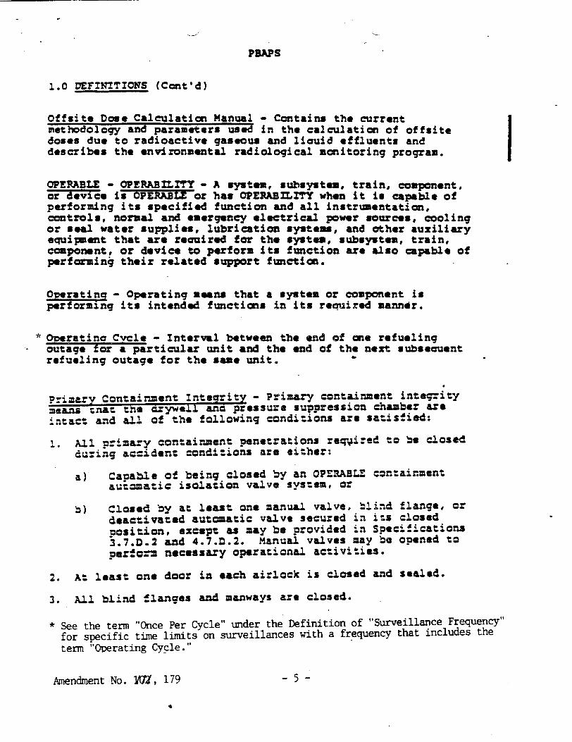
Offsite Dose Calculation Manual - Contains the current methodology and parameters used in the calculation of offsite doses due to radioactive gaseous and liquid effluents and describes the environmental radiological monitoring program.
OPERABLE - OPERABILITY - A system, subsystem, train, component, or device is OPERABLE or has OPERABILITY when it is capable of performing its specified function and all instrumentation, controls, normal and emergency electrical power sources, cooling or seal water supplies, lubrication systems, and other auxiliary equipment that are reauired for the system, subsystem, train, component, or device to perform its function are also capable of performin4 their related support function.
Operating - Operating means that a system or component is pertorminq its intended functions in its required manner.
* ODeratine Cycle - Interval between the end of one refueling
outage for a particular unit and the end of the next subsecuent refueling outage for the same unit.
Primary Containment Integrity - Primary containment integrity means Enat the =7ywell ano pressure suppression chamber are in"tact and all of the following conditions are satisfied:
1. All primary containment penetrations reqaired to be closed during accident conditions are either:
a) Capable of being closed by an OPERABL czntainment auizmatic isolation valve system, or
b) Closed by at least one manual valve, blind flange, or deactivated automatic valve secured in i-s closed position, except as may be provided in Specifications 3.7.D.2 and 4.7.Z.2. Manual valves may be opened to pegrtf.m necessary operational act.ivities.
2. At least one door in each airlock is closed and sealed.
3. All blind !langes and manways are closed.
* See the term "Once Per Cycle" under the Definition of "Surveillance Frequency" for specific time limits on surveillances with a frequency that includes the
term "Operating Cycle."
Amendment No. YAZ, 179 -5 -
PBAPS
1.0 DEFINITIOWS (Cont'd)
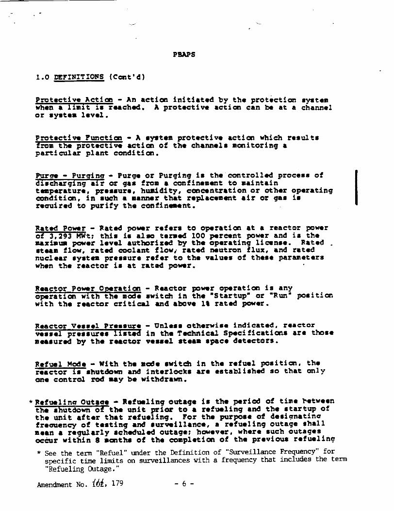
Protective Action - An action initiated by the protection system when a limit is reached. A protective action can be at a channel or system level.
Protective Function - A system protective action which results from the protective action of the channels monitoring a particular plant condition.
Puae - Purging- Purge or Purging is the'controlled process of
discharging air or gas from a confinement to maintain temperature, pressure, humidity, concentration or other operating condition, in such a manner that replacement air or gas is reauired to purify the confinement.
Rated Power - Rated power refers to operation at a reactor power of 3,293 MWt; this is also termed 100 percent power and is the maximum power level authorized by the operating license. Rated steam flow, rated coolant flowi rated neutron flux, and rated nuclear system pressure refer to the values of these parameters when the reactor is at rated power.
Reactor Power Operation - Reactor power operation is any operation with the mode switch in the OStartup" or 'Run" position with the reactor critical and above 1% rated power.
Reactor Vessel Pressure - Unless otherwise indicated, reactor vessel pressures listed in the Technical Specifications are those measured by the reactor vessel steam space detectors.
Refuel Mode - With the mode switch in the refuel position, the reactor is shutdown and interlocks are established so that only one control rod may be withdrawn.
*Refuelina Outage - Refueling outage is the period of time between the shutdown of the unit prior to a refueling and the startup of the unit after that refueling. For the purpose of desiqnatina freouency of testing and surveillance, a refueling outage shall mean a regularly scheduled outage; however, where such outages occur within 8 months of the completion of the previous refueling
* See the term "Refuel" under the Definition of "Surveillance Frequency" for specific time limits on surveillances with a frequency that includes the term "Refueling Outage."
Amendment No. f•, 179 -6 -
Unit 2 PBAPS
1.0 DEFINITIONS (Cont'd)
Simulated Automatic Actuation - Simulated automatic actuation mans applying a simulated signal to the sensor to actuate the circuit in question.
Site Boundary - That line beyond which the land Is not owned, leased or otherwise controlled by licensee.
Source Check - A source check shall be the qualitative assessment of channel response when the channel sensor is exposed to a radioactive source.
Startup/Hot Standby Mode - In this mode the reactor protection scrm trips, initiated by condenser low vacuum and.main steam line isolation valve closure are bypassed, the reactor protection system is energized with IRM neutron monitoring system trip, the APRM 15% high flux trip, and control rod withdrawal interlocks in service. This is often referred to as just Startup Mode. This is intended to imply the Startup/Hot Standby position of the mode switch.
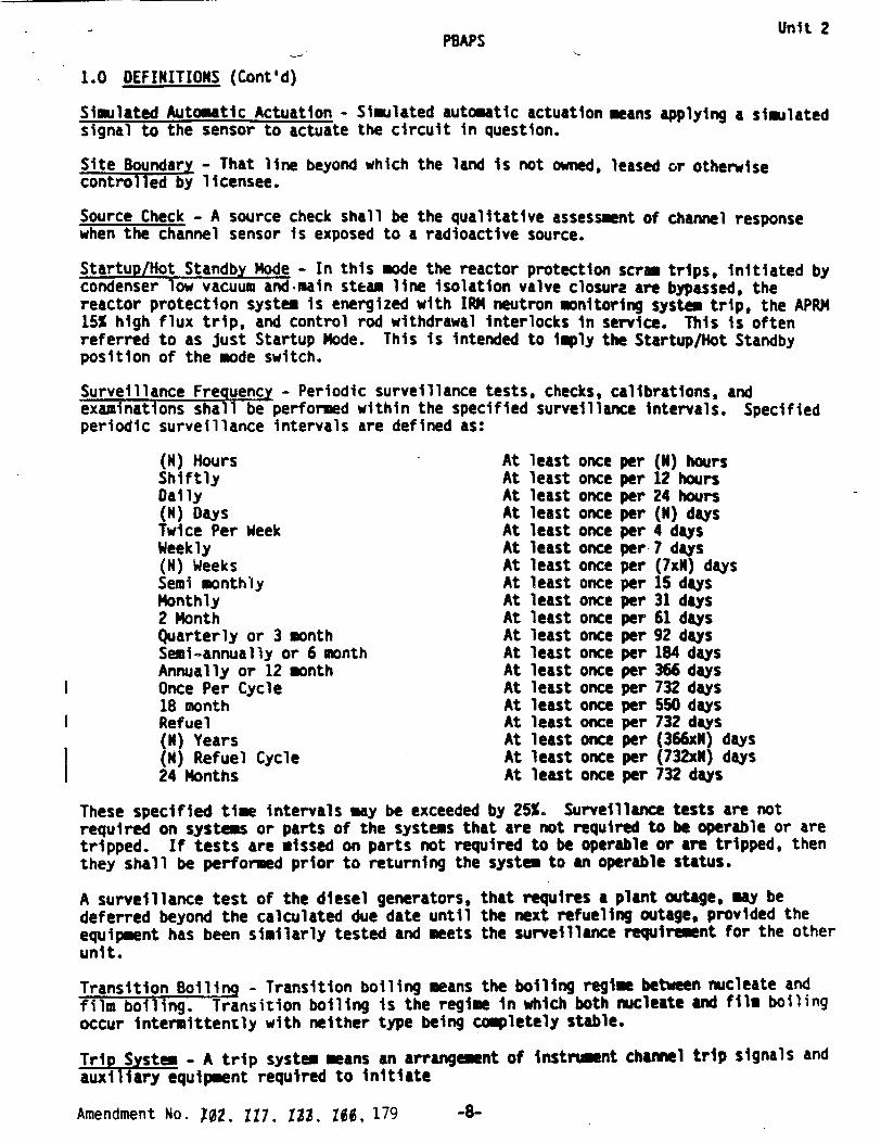
Surveillance Frequency - Periodic surveillance tests, checks, calibrations, and examinations shall be performed within the specified surveillance intervals. Specified periodic surveillance intervals are defined as:
(N) Hours Shiftly Dai ly (N) Days Twice Per Week Weekly (N) Weeks Semi monthly Monthly 2 Month Quarterly or 3 month Semi-annually or 6 month Annually or 12 month Once Per Cycle 18 month Refuel (N) Years (N) Refuel Cycle 24 Months
At At At At At At At At At At At At At At At At At At At
least least least least least least least least least least least least least least least least least least least
once once once once once once once once once once once once once once once once once once once
per per per per per per per per per per per per per per per per per per per
(N) hours 12 hours 24 hours (N) days 4 days 7 days (70x) days 15 days 31 days 61 days 92 days 184 days 366 days 732 days 550 days 732 days (366xN) days (732xN) days 732 days
These specified time intervals may be exceeded by 25%. Surveillance tests are not required on systems or parts of the systems that are not required to be operable or are tripped. If tests are missed on parts not required to be operable or are tripped, then they shall be performed prior to returning the system to an operable status.
A surveillance test of the diesel generators, deferred beyond the calculated due date until equipment has been similarly tested and meets unit.
that requires a plant outage, may be the next refueling outage, provided the the surveillance requirement for the other
Transition Boiling - Transition boiling means the boiling regime between nucleate and film boiling. Transition boiling is the regime in which both nucleate and film boiling occur intermittently with neither type being completely stable.
Trip System - A trip system means an arrangement of instrument channel trip signals and auxiliary equipment required to initiate
Amendment No. 102. Ill. 123, I66, 179
I I
I
-8-
Unit 2
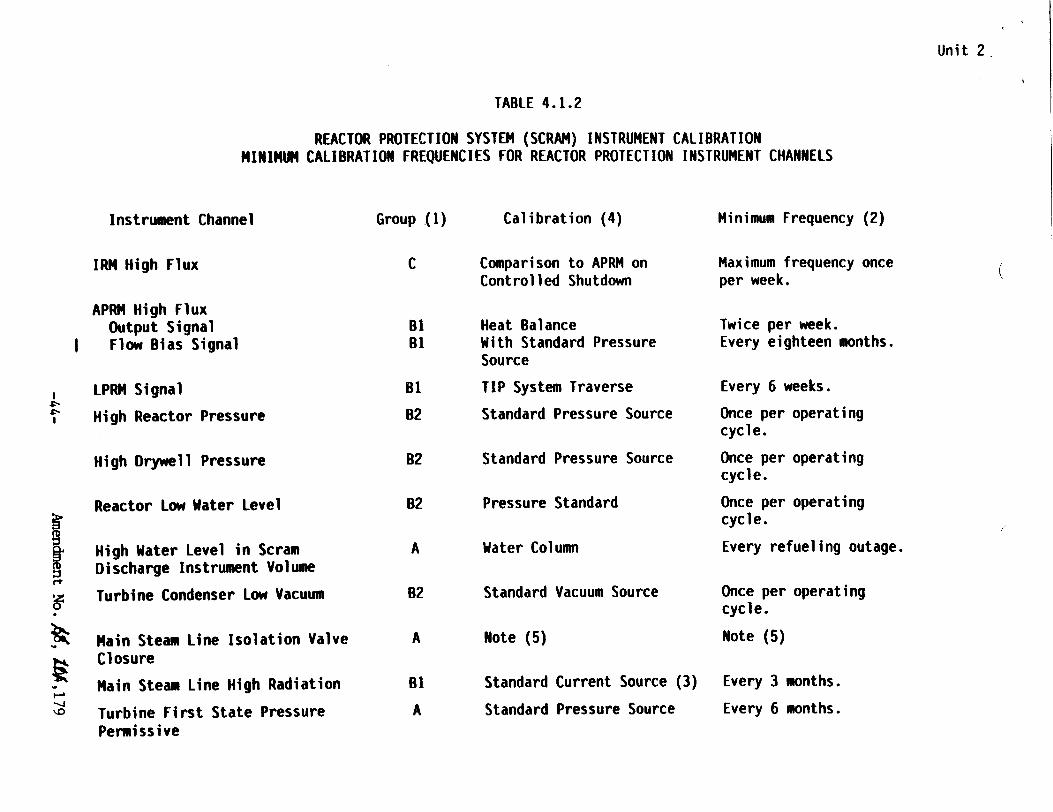
TABLE 4.1.2
REACTOR PROTECTION SYSTEM (SCRAM) INSTRUMENT CALIBRATION MINIMUM CALIBRATION FREQUENCIES FOR REACTOR PROTECTION INSTRUMENT CHANNELS
Instrument Channel
IRM High Flux
APRM High Flux Output Signal Flow Bias Signal
LPRM Signal
High Reactor Pressure
High Drywell Pressure
Reactor Low Water Level
S High Water Level in Scram Discharge Instrument Volume
, Turbine Condenser Low Vacuum
~ Main Steam Line Isolation Valve • Closure
Main Steam Line High Radiation
~ Turbine First State Pressure Permissive
Group (1)
C
BI Bi
B'
B2
B2
B2
A
B2
A
B2
A
Calibration (4)
Comparison to APRM on Controlled Shutdown
Heat Balance With Standard Pressure Source
TIP System Traverse
Standard Pressure Source
Standard Pressure Source
Pressure Standard
Water Column
Standard Vacuum Source
Note (5)
Standard Current Source (3)
Standard Pressure Source
Minimum Frequency (2)
Maximum frequency once per week.
Twice per week. Every eighteen months.
Every 6 weeks.
Once per operating cycle.
Once per operating cycle.
Once per operating cycle.
Every refueling outage.
Once per operating cycle.
Note (5)
Every 3 months.
Every 6 months.
(

(4
a
-a
'-4
*�h
-I
Instrument Channel
13) HPCI and RCIC Steam Line Low Pressure
14) HPCI Suction Source Levels
15) 4KV Emergency Power System Voltage Relays (HGASV)
16) ADS Relief Valves Bellows Pressure Switches
17) LPCI/Cross Connect Valve Position
18) Condensate Storage Tank Level (RCIC) (7)
19) 4KV Emergency Power Source Degraded Voltage Relays (IAV.CV-6.ITE)
Instrument Functional Test
(I)
(1)
Once/operating cycle
Once/operating cycle
Once/refueling cycle
Once/3 months
Once/month
Calibration Frequency
Once/3 months
Once/3 month
Once/5 years
Once/operating cycle
N/A
Once/operating cycle
Once/eighteen months
Instrument Check
None
None
None
None
N/A
Once/day
None
TABLE 4.2.B (CONTINUED) MINIMUM TEST AND CALIBRATION FREQUENCY FOR CSCS
S
Unit 2

TABLE 4.2.F MINIMUM TEST AND CALIBRATION FREQUENCY FOR SURVEILLANCE INSTRUMENTATION
Instrument Channel
18) Drywell High Range Radiation Monitors
I 19, Main Stack High Range Radiation Monitor
I 20) Reactor Bldg. Roof Vent High Range Radiation Monitor
21) Urywell Hydrogen Concentration Analyzer and Monitor
Calibration Frequency
Once/operating cycle**
Once/eighteen months
Once/eighteen months
Quarterly***
Instrument Check
Once/month
Once/month
Once/month
Once/month
* Perform instrument functional check once per operating cycle.
** Channel calibration shall consist of an electronic calibration of the channel, not including the detector, for range decades above IOR/hr and a one point calibration check of the detector below IOR/hr with an installed or portable gamma source.
*** At least a two-point calibration using sample gas.
Unit 2
I
Unit 2
PBAPS
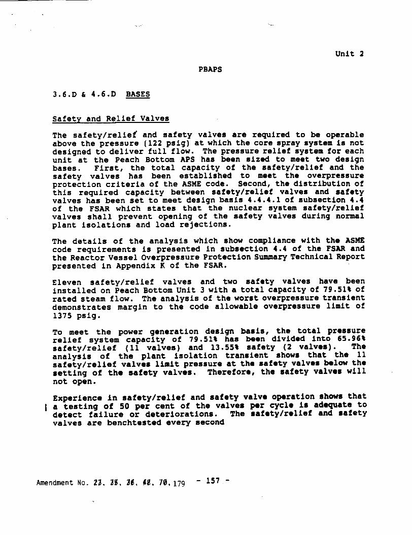
3.6.D & 4.6.D BASES
Safety and Relief Valves
The safety/relief and safety valves are required to be operable above the pressure (122 psig) at which the core spray system is not designed to deliver full flow. The pressure relief system for each unit at the Peach Bottom APS has been sized to meet two design bases. First, the total capacity of the safety/relief and the safety valves has been established to meet the overpressure protection criteria of the ASME code. Second, the distribution of this required capacity between safety/relief valves and safety valves has been set to meet design basis 4.4.4.1 of subsection 4.4 of the FSAR which states that the nuclear system safety/relief valves shall prevent opening of the safety valves during normal plant isolations and load rejections.
The details of the analysis which show compliance with the ASME code requirements is presented in subsection 4.4 of the FSAR and the Reactor Vessel Overpressure Protection Summary Technical Report presented in Appendix K of the FSAR.
Eleven safety/relief valves and two safety valves have been installed on Peach Bottom Unit 3 with a total capacity of 79.51% of rated steam flow. The analysis of the worst overpressure transient demonstrates margin to the code allowable overpressure limit of 1375 psig.
To meet the power generation design basis, the total pressure relief system capacity of 79.51% has been divided into 65.96% safety/relief (11 valves) and 13.55% safety (2 valves). The analysis of the plant isolation transient shows that the 11 safety/relief valves limit pressure at the safety valves below the setting of the safety valves. Therefore, the safety valves will not open.
Experience in safety/relief and safety valve operation shows that a testing of 50 per cent of the valves per cycle is adequate to detect failure or deteriorations. The safety/relief and safety valves are benchtested every second
Amendment No. M 39, 30, , , 70,179 - 157 -

Unit 2
PBAPS
LIMITING CONDITIONS FOR OPERATION SURVEILLANCE REQUIREMENTS
3.7.A Primary Containment (Cont'd.) 4.7.A Primary Containment (Cont'd.)
f. Local leak rate tests (LLRT's) shall be performed on the primary containment testable penetrations and isolation valves in accordance with Tables 3.7.2, 3.7.3, & 3.7.4 at a pressure of 49.1 psig (except for the main steam isolation valves, see below) per 1OCFR50 Appendix J requirements. Bolted double-gasketed seals shall be tested whenever the seal is closed after being opened and at least once per operating cycle, not to exceed the requirements of 1OCFR5O Appendix J.
The Main Steamline isolation valves shall be tested at a pressure of 25 psig for leakage during each refueling outage, but in no case exceeding the requirements of 1OCFR50 Appendix J. If a total leakage rate of 11.5 scf/hr for any one main steamline isolation valve is exceeded, repairs and retest shall be performed to correct the condition.
g. Continuous Leak Rate Monitor
When the primary containment is inerted, the containment shall be continuously monitored for gross leakage by review of the inerting system makeup requirements. This monitoring system may be taken out of service for maintenance but shall be returned to service as soon as practicable.
-169-Amendment No. 1$4, 179
Unit 2
PBAPS
LIMITING CONDITIONS FOR OPERATION SURVE ILL.ANCE REGUIREMENTS
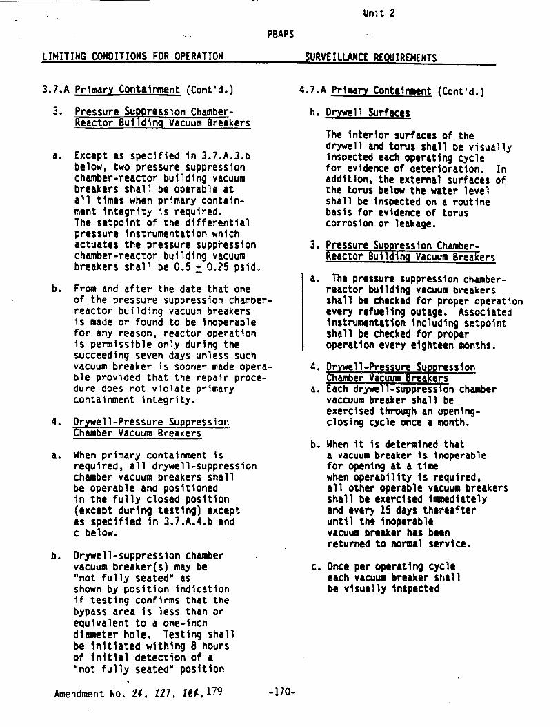
3.7.A Primary Containment (Cont'd.)
3. Pressure Suppression ChamberReactor Building Vacuum Breakers
a. Except as specified in 3.7.A.3.b below, two pressure suppression chamber-reactor building vacuum breakers shall be operable at all times when primary containment integrity is required. The setpoint of the differential pressure instrumentation which actuates the pressure suppression chamber-reactor building vacuum breakers shall be 0.5 + 0.25 psid.
b. From and after the date that one of the pressure suppression chamberreactor building vacuum breakers is made or found to be inoperable for any reason, reactor operation is permissible only during the succeeding seven days unless such vacuum breaker is sooner made operable provided that the repair procedure does not violate primary containment integrity.
4. Drywell-Pressure Suppression Chamber Vacuum Breakers
a. When primary containment is required, all drywell-suppression chamber vacuum breakers shall be operable ana positioned in the fully closed position (except during testing) except as specified in 3.7.A.4.b and c below.
b. Drywell-suppression chamber vacuum breaker(s) may be "not fully seated" as shown by position indication if testing confirms that the bypass area is less than or equivalent to a one-inch diameter hole. Testing shall be initiated withing 8 hours of initial detection of a "not fully seated" position
4.7.A Primary Containment (Cont'd.)
h. Drywell Surfaces
The interior surfaces of the drywell and torus shall be visually inspected each operating cycle for evidence of deterioration. In addition, the external surfaces of the torus below the water level shall be inspected on a routine basis for evidence of torus corrosion or leakage.
3. Pressure Suppression ChamberReactor Building Vacuum Breakers
a. The pressure suppression chamberreactor building vacuum breakers shall be checked for proper operation every refueling outage. Associated instrumentation including setpoint shall be checked for proper operation every eighteen months.
4. Drywell-Pressure Suppression Chamber Vacuum Breakers
a. Each drywell-suppression chamber vaccuum breaker shall be exercised through an openingclosing cycle once a month.
b. When it is determined that a vacuum breaker is inoperable for opening at a time when operability is required, all other operable vacuum breakers shall be exercised immediately and ever) 15 days thereafter until the inoperable vacuum breaker has been returned to normal service.
c. Once per operating cycle each vacuum breaker shall be visually inspected
Amendment No. 24, 127, lg4,179
SURVEILUUICE REOUIREMENTS
-170-

Unit 2
LIMITING CONDITIONS FOR OPERATION SURVEILLANCE REQUIREMENTS
3. If any reactor instrumentation line excess flow check valve is inoperable, within 4 hours either:
a. Restore the inoperable excess flow check valve to operable status or,
b. Isolate the instrument line and declare the associated instrument inoperable.
c. Otherwise be in at least Hot Shutdown wiLhin the next 12 hours and in Cold Shutdown within the following 24 hours.
3.7.E Large Primary Containment Purge/Vent Isolation Valves
1. The large primary containment purge/vent isolation valves (6 and 18 inches) shall be operated in accoroance with specification 3.7.0 and with specifications 3.7.E.2 and 3.7.E.3 below.
2. When the reactor pressure is greater than 100 psig, and the reactor critical, and the reactor mode switch in the "Startup" or "Run" mode, primary containment purging or venting shall be subject to the following restrictions:
a. The large primdry containment purge/vent isolation valves may be opened only for inerting, de-inerting, and pressure control.
b. The accumulated time a purge or vent flow path exists shall be limited to 90 hours per calendar year.
3. At least once per operating cycle the operability of the reactor coolant system instrument line flow check valves shall be verified.
4.7.E Large Primary Containment Purge/Vent Isolation Valves
1. The inflatable seals for the large containment ventilation isolation valves shall be replaced at least once every second refueling outage.
2. The LLRT leak rate for the large containment ventilation isolation valves shall be compared to the previously measured leak rate to detect excessive valve degradation.
-178-Amendment No. 1#4, 179
t
PBAPS
Unit 2
PBAPS
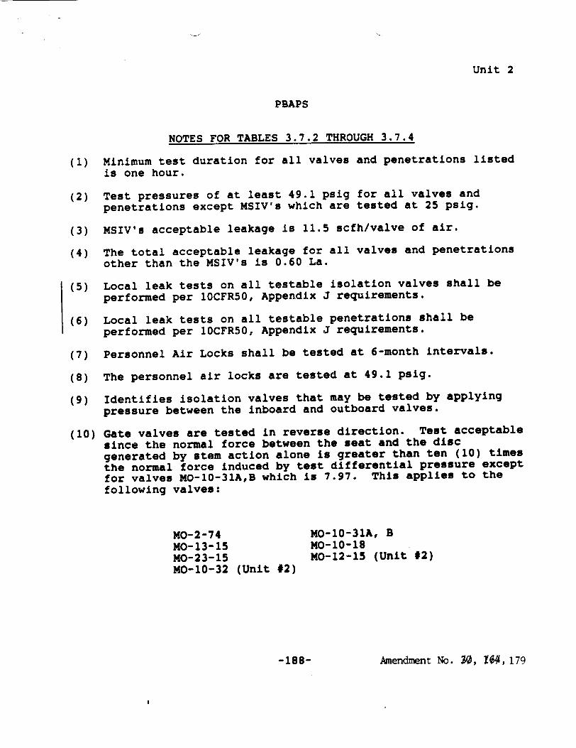
NOTES FOR TABLES 3.7.2 THROUGH 3.7.4
(1) Minimum test duration for all valves and penetrations listed is one hour.
(2) Test pressures of at least 49.1 psig for all valves and
penetrations except MSIV's which are tested at 25 psig.
(3) MSIV's acceptable leakage is 11.5 scfh/valve of air.
(4) The total acceptable leakage for all valves and penetrations other than the MSIV's is 0.60 La.
(5) Local leak tests on all testable isolation valves shall be performed per 10CFR50, Appendix J requirements.
(6) Local leak tests on all testable penetrations shall be performed per 10CFR50, Appendix J requirements.
(7) Personnel Air Locks shall be tested at 6-month intervals.
(8) The personnel air locks are tested at 49.1 psig.
(9) Identifies isolation valves that may be tested by applying pressure between the inboard and outboard valves.
(10) Gate valves are tested in reverse direction. Test acceptable since the normal force between the seat and the disc generated by stem action alone is greater than ten (10) times the normal force induced by test differential pressure except for valves MO-10-31A,B which is 7.97. This applies to the following valves:
MO-2-74 MO-10-31A, B MO-13-15 MO-10-18 MO-23-15 MO-12-15 (Unit #2) M0-10-32 (Unit #2)
Amendment No. 30, 104, 179-188-

Unit 2
PBAPS
3.7.A & 4.7.A BASES (Cont'd.)
The design basis loss-of-coolant accident was evaluated at the primary containment maximum allowable accident leak rate of 0.5%/day at 56 psig. Calculations made by the AEC staff with leak rate and a standby gas treatment system filter efficiency of 90% for halogens and assuming the fission product release fractions stated in TID 14844, show that the maximum total whole body passing cloud dose is about 1.0 REM and the maximum total thyroid dose is about 14 REM at .4500 meters from the stack over an exposure duration of two hours. The resultant doses that would occur for the duration of the accident at the low population zone distance of 7300 meters are about 2.5 REM total whole body and 105 REM total thyroid. Thus, the doses reported are the maximum that would be expected in the unlikely event of a design basis loss-of-coolant accident. These doses are also based on the assumption of no holdup in the secondary containment resulting in a direct release of fission products from the primary containment through the filters and stack to the environs. Therefore, the specified primary containment leak "rate and filter efficiency are conservative and provide margin between expected off-site doses and 10 CFR 100 guidelines.
The water in the suppression chamber is used only for cooling in the event of an accident; i.e., it is not used for normal operation; therefore, a daily check of the temperature and volume is adequate to assure that adequate heat removal capability is present.
Drywell Interior
The interiors of the drywell and suppression chamber are painted to prevent rusting. The inspection of the paint during each major -refueling outage, assures the paint is intact. Experience with this type of paint at fossil fueled generating stations indicates that the inspection interval is adequate.
Post LOCA Atmosphere Dilution
In order to ensure that the containment atmosphere remains inerted, i.e. the oxygen-hydrogen mixture below the flammable limit, the capability to inject nitrogen into the containment after a LOCA is provided. During the first year of operation the normal inerting nitrogen makeup system will be available for this purpose. After that time the specifically designed CAD system will serve as the post-LOCA Containment Atmosphere Dilution System. By maintaining a minimum of 2000 gallons of liquid N. in the storage tank it is assured that a seven-day supply of N2 for post-LOCA containment inerting is available. Since the inerting makeup system is continually functioning, no
Amendment No. 112,179 - 193 -
PBAPS
LIMITING CONDITIONS FOR OPERATION
Unit 2
SURVE I LLANCE REQU I RE1ENTS
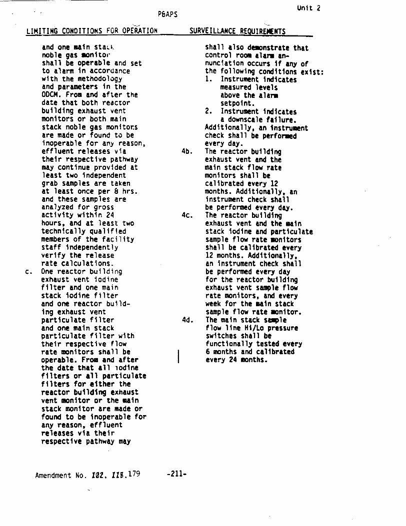
and one main staLk noble gas monitor shall be operable and set to alarm in accordance with the methodology and parameters in the ODCM. From and after the date that both reactor building exhaust vent monitors or both main stack noble gas monitors are made or found to be inoperable for any reason, effluent releases via their respective pathway may continue provided at least two independent grab samples are taken at least once per 8 hrs. and these samples are analyzed for gross activity within 24 hours, and at least two technically qualified members of the facility staff independently verify the release rate calculations.
c. One reactor building exhaust vent iodine filter and one main stack iodine filter and one reactor building exhaust vent particulate filter and one main stack particulate filter with their respective flow rate monitors shall be operable. From and after the date that all iodine filters or all particulate filters for either the reactor building exhaust vent monitor or the main stack monitor are made or found to be inoperable for any reason, effluent releases via their respective pathway may
shall also demonstrate that control room alarm annunciation occurs if any of the following conditions exist: 1. Instrument indicates
measured levels above the alarm setpoint.
2. Instrument indicates a downscale failure.
Additionally, an instrument check shall be performed every day.
4b. The reactor building exhaust vent and the main stack flow rate monitors shall be calibrated every 12 months. Additionally, an instrument check shall be performed every day.
4c. The reactor building exhaust vent and the main stack iodine and particulate sample flow rate monitors shall be calibrated every 12 months. Additionally, an instrument check shall be performed every day for the reactor building exhaust vent sample flow rate monitors, and every week for the main stack sample flow rate monitor.
4d. The main stack sample flow line Hi/Lo pressure switches shall be functionally tested every 6 months and calibrated every 24 months.
Amendment No. 10iZ, 1S.179 -211-
LIMITING CONDITIONS FOR ut'ERATION
Unit 2PBAPS
SUR'VEILLANCE REQUIREMENTS
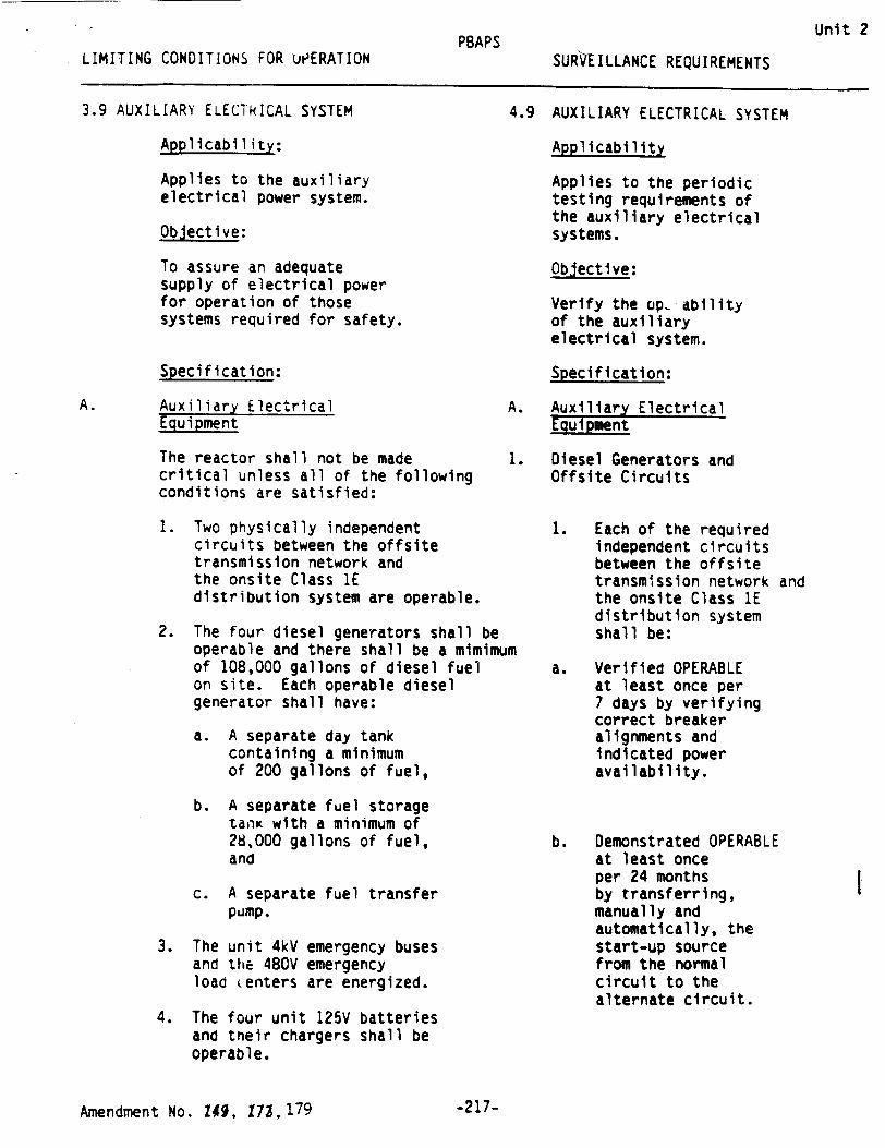
3.9 AUXILIARY ELECTRICAL SYSTEM 4
Applicability:
Applies to the auxiliary electrical power system.
Objective:
To assure an adequate supply of electrical power for operation of those systems required for safety.
Specification:
A. Auxiliary Electrical A. Equipment
The reactor shall not be made critical unless all of the following conditions are satisfied:
1. Two physically independent circuits between the offsite transmission network and the onsite Class 1E distribution system are operable.
2. The four diesel generators shall be operable and there shall be a mimimum of 108,000 gallons of diesel fuel on site. Each operable diesel generator shall have:
a. A separate day tank containing a minimum of 200 gallons of fuel,
b. A separate fuel storage ta1nK with a minimum of 28,000 gallons of fuel, and
c. A separate fuel transfer pump.
3. The unit 4kV emergency buses and thE 480V emergency load (enters are energized.
4. The four unit 125V batteries and their chargers shall be operable.
.9 AUXILIARY ELECTRICAL SYSTEM
Applicability
Applies to the periodic testing requirements of the auxiliary electrical systems.
Objective:
Verify the op, ability of the auxiliary electrical system.
Specification:
. Auxiliary Electrical Equipment
* Diesel Generators and Offsite Circuits
1. Each of the required independent circuits between the offsite transmission network and the onsite Class 1E distribution system shall be:
a. Verified OPERABLE at least once per 7 days by verifying correct breaker alignments and indicated power availability.
b. Demonstrated OPERABLE at least once per 24 months by transferring, manually and automatically, the start-up source from the normal circuit to the alternate circuit.
Amendment No. Z49, 73,1 7 9
I
-217-

Unit 2
PBAPS
LIMITING CONDITION FOR OPERATION SURVEILLANCE REQUIREMENTS
4.9.A.1.2 (Continued)
e. At least once every 31 days by obtaining a sample of fuel oil from the storage tank in accordance with ASTM D2276-78, and verifying that total particulate contamination is less than 10mg/liter when checked in accordance with ASTM D2276-78, Method A, except that the filters specified in ASTM D2276-78, Sections 5.1.6 and 5.1.7, may have a nominal pore size of up to three (3) microns.
f. At least once per 18 months by:
1. Subjecting the diesel to an inspection in accordance with procedures prepared in conjunction with its manufacturer's recommendations for this class of standby service.
g. At least once per 24 months by:
1. Verifying the diesel generator capability to reject a load of greater than or equal to that of the RHR Pump Motor for each diesel generator while maintaining voltage within 4160 ± 410 volts and frequency at 60 ± 1.2hz.
2. Verifying the diesel generator capability to reject an indicated load of 2400 kW-2600 Kw without tripping. The generator voltage shall not exceed the initial value (4160 ± 410 volts) by more than 660 volts during and following the load rejection.
-218d-Amendment No. 173,179
Unit 2
PBAPS LIMITING CONDITIONS FOR OPERATION SURVEILLANCE REQUIREMENTS
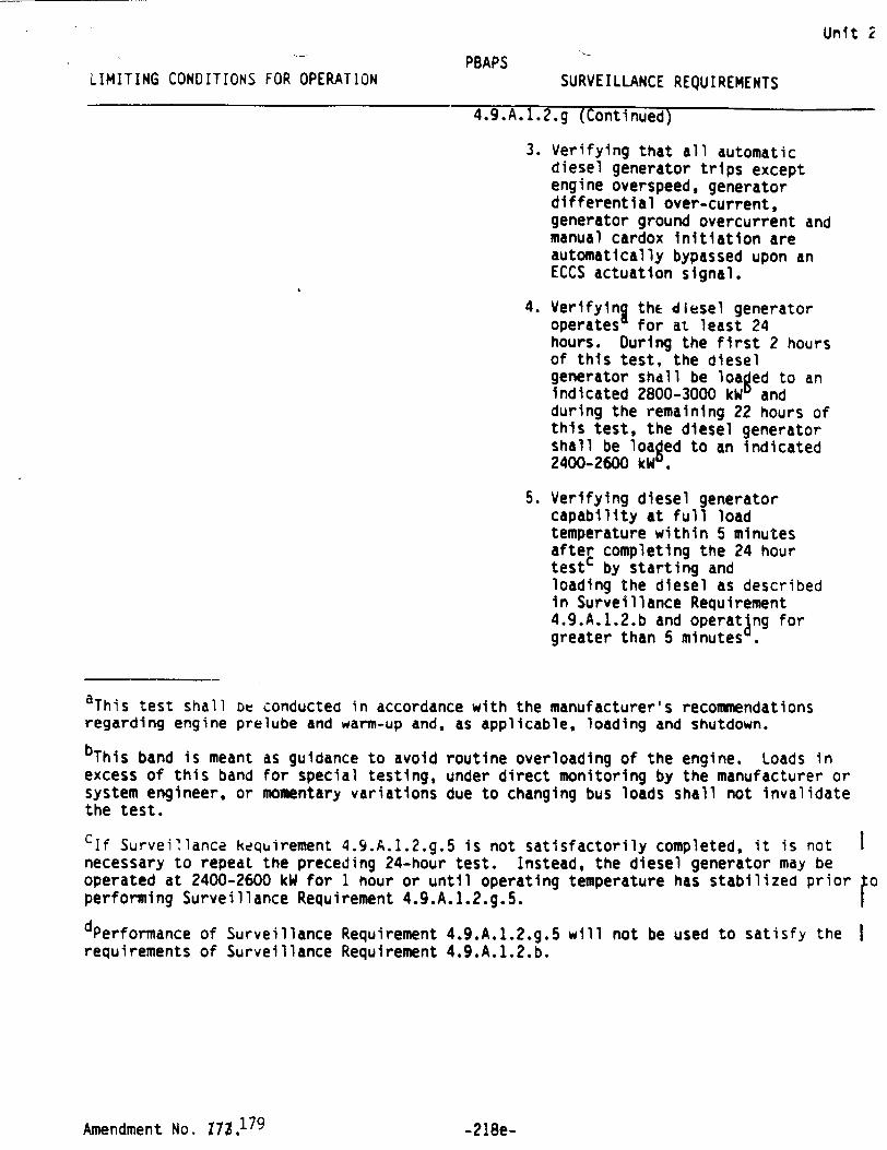
4.9.A.1.2.g (Continued)
3. Verifying that all automatic diesel generator trips except engine overspeed, generator differential over-current, generator ground overcurrent and manual cardox initiation are automatically bypassed upon an ECCS actuation signal.
4. Verifying the diesel generator operates for at least 24 hours. During the first 2 hours of this test, the diesel generator shall be loaged to an indicated 2800-3000 kWu and during the remaining 22 hours of this test, the diesel generator shall be loaged to an indicated 2400-2600 kW
5. Verifying diesel generator capability at full load temperature within 5 minutes after completing the 24 hour testc by starting and loading the diesel as described in Surveillance Requirement 4.9.A.1.2.b and operating for greater than 5 minutes
aThis test shall ot conducted in accordance with the manufacturer's recommendations regarding engine prelube and warm-up and, as applicable, loading and shutdown.
bThis band is meant as guidance to avoid routine overloading of the engine. Loads in excess of this band for special testing, under direct monitoring by the manufacturer or system engineer, or momentary variations due to changing bus loads shall not invalidate the test.
Clf Surveillance kequirement 4.9.A.1.2.g.5 is not satisfactorily completed, it is not necessary to repeat the preceding 24-hour test. Instead, the diesel generator may be operated at 2400-2600 kW for 1 hour or until operating temperature has stabilized prior 0o performing Surveillance Requirement 4.9.A.1.2.g.5. f
dPerformance of Surveillance Requirement 4.9.A.1.2.g.5 will not be used to satisfy the requirements of Surveillance Requirement 4.9.A.1.2.b.
Amendment No. 1,179- e-218e-
Unit "PBAPSLIMITING CONDITIONS FOR OPERATION SURVEILLANCE REQUIREMENTS
4.9.A.1.2 (Continued)
6. Verifying that the fuel transfer pump transfers fuel from each fuel storage tank to the day tank of each diesel via the installed cross connection lines.
h. At least once each operating
cycle by:
1. Simulating a loss-of-offsite power by itself, and:
a) Verifying deenergization of the emergency busses and load shedding from the emergency busses.
b) Verifying the dijsel generator starts on the auto-start signal, energizes the emergency busses within 10 seconds, energizes the permanent and auto-connected loads through the individual load timers and operates for greater than or equal to 5 minutes.
After energization, the steady-state voltage and frequency of the emergency busses shall be maintained at 4160 + 410 volts and 60 + 1.2 Hz during this test.
aThis test shall be conducted in accordance with the manufacturer's recommendations regarding engine prelube and warm-up and, as applicable, loading and shutdown.
Amendment No. 173, 179 -218f -
Unit 2
PBAPS
LIMITING CONDITIONS FOR OPERATION SURVEILLANCE REQUIREMENTS
4.9.A.1.2 (Continued)
4. Verifying the diesel generator's capability to:
a) Synchronize with the offsite power source while the generator is loaded with its emergency loads upon a simulated restoration of offsite power.
b) Transfer its loads to the offsite power source, and
c) Be restored to its standby status.
i. At least once per 10 years or after any modifications which could affect diesel generator interdependence by starting* all four diesel generators simultaneously and verifying that all four diesel generators accelerate to at least 855 rpm in less than or equal to 10 seconds.
j. At least once per 10 years by draining each fuel oil tank, removing the accumulated sediment and cleaning the tank using a sodium hypochlorite or equivalent solution.
k. The fuel oil storage tank cathodic protection system shall be checked as follows:
1. At least once every twelve months perform a test to determine whether the cathodic protection is adequate, and
'This test shall be conducted in accordance with the manufacturer's recommendations regarding engine prelube and warmup and, as applicable, loading and shutdown.
Amendment No. i17, 179
I
-218h-
4
Unit 2
PBAPS
LIMITING CONDITIONS FOR OPERATION SURVEILLANCE REQUIREMENTS
4.9.A.1.2 (Continued)
2. At least once every two months inspect the cathodic protection rectifiers.
1. If the number of failures during the last 20 valid demandsd is less than or equal to 1, the test frequency shall be at least once per 31 days.
If the number of failures during the last 20 valid demands is greater than or equal to 2, the test frequency shall be at least once per 7 days'.
m. All diesel generator failures, valid or non-valid, shall be reported to the Commission in a Special Report within 30 days. Reports of the diesel generator failures shall include the information recommended in Regulatory Position C.3.b of Regulatory Guide 1.108, Revision 1, August 1977.
dCriteria for determining the number of failures and number of valid demands shall be in accordance with Regulatory Position C.2.e of Regulatory Guide 1.108, but determined on a per diesel generator basis.
"The associated test frequency shall be maintained until seven consecutive failure free demands have been performed And the number of failures in the last 20 demands have been reduced to one. For the purposes of determining the required frequency, the previous test failure count may be reduced to zero if a complete diesel overhaul to like-new condition is completed. This diesel overhaul, including appropriate post-maintenance operation and testing, shall be specifically approved by the manufacturer and acceptable diesel reliability must be demonstrated. The reliability criterion shall be the successful completion of 14 consecutive tests. Ten of these tests may be slow starts in accordance with Surveillance Requirements 4.9.A.1.2.a.3 and 4.9.A.1.2.a.4 and four tests shall be fast starts in accordance with the Surveillance Requirement 4.9.A.1.2.b. If this criterion is not satisfied during the first series of tests, any alternate criterion to be used to reset the valid failure count to zero requires NRC approval.
Amendment No. 172, 179 -218i-
Unit 2
PBAPS
LIMITING CONDITIONS FOR OPERATION SURVEILLANCE REQUIREMENTS
4.9.A.2 Unit Batteries
a. Every week the specific gravity, the voltage and temperature of the pilot cell and overall battery voltage shall be measured and logged.
b. Every three months the measurements shall be made of voltage of each cell to nearest 0.1 Volt, specific gravity of each cell, and temperature of every fifth cell. These measurements shall be logged.
c. The station batteries shall be subjected to a performance test every second refueling outage and a service test during the other refueling outage. In lieu of the performance test every second refueling outage, any j battery that shows "signs of degradation or has reached 85% of its service life" shall be subjected to an annual performance test. The service test need not be performed on the refueling outage during which the performance test was conducted. The specific gravity and voltage of each cell shall be determined after the discharge and logged.
4.9.A.3 Swing Buses
a. Every two months the swing buses supplying power to the Low Pressure Coolant Injection System (LPCIS) valves shall be tested to assure that the transfer circuits operate as designed.
-218j- Amendment No. AU•, 179

LIMITING CONDITIONS FOR ¢. .RATION4.CD.O.TSURVEILLAMCE RF T T
4. 11.0.3
Visual inspection of snubbers required to be operable under the provisions of 3.11.0.1 shall verify that 1) there are no indications of damage or impaired operability, 2) attaclments to the foundations or supporting structure are functional, and 3) fasteners for the attachment of the snubber to the component and to the snubber anchorage are functional.
Snubbers which appear to be inoperable as a result of visual inspections shall be classified as unacceptable and may be reclassified acceptable for the purpose of establishing the next visual inspection interval, providing that 1) the cause of the rejection is clearly established and remedied for that particular snubber and for other generically susceptible snubbers; and 2) the affected snubber is functionally tested in the as found condition and determined operable per Specification 4.11.0.7 or 4.11.0.8, as applicable. All snubbers found connected to an inoperable comon hydraulic fluid reservoir shall be counted as unacceptable for determining the next inspection interval. A review and evaluation shall be performed and documented to justify continued operation with an unacceptable snubber. If continued operation cannot be justified, the snubber shall be declared inoperable and the Limiting Conditions for Operation shall be met.
4.11.0.4
Functional Test
*Performance of 4.11.D.4(a) with an operating cycle of 732 days is approved for the operating cycle following refueling outage 2R010 only.
*a) Once each operating cycle, during shutdown, a representative saqple of 101 of each type of (mechanical or hydraulic) snubber required to be operable under the provisions of 3.11.0.1 shall be functionally tested either in place or in a bench test. For every unit found to be inoperable an additional 101 of that type of snubber shall be functionally tested until no more failures are found or all snubbers of that type have been tested. The functional test requirmmnts for mechanical
-234b- Amwxmne tNo. 10I, 197.AfJ?, 1791
Unit 2
Unit 2
PBAPS
I TMTTTUI rfluflTTTflN� FAA APFRATTON SURVEILLANCE REQUIREMENTS,ITM'* I rIr.J nl -.. .r. n . .. . . --
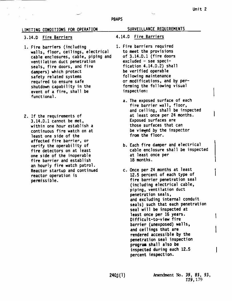
3.14.D Fire Barriers
1. Fire barriers (including walls, floor, ceilings, electrical cable enclosures, cable, piping and ventilation duct penetration seals, fire doors, and fire dampers) which protect safety related systems required to ensure safe shutdown capability in the event of a fire, shall be functional.
2. If the requirements of 3.14.D.1 cannot be met, within one hour establish a continuous fire watch on at least one side of the affected fire barrier, or verify the operability of fire detectors on at least one side of the inoperable fire barrier and establish an hourly fire watch patrol. Reactor startup and continued reactor operation is permissible.
4.14.D Fire Barriers
1. Fire barriers required to meet the provisions of 3.14.D.1 (fire doors excluded - see specification 4.14.D.2) shall be verified operable following maintenance or modifications, and by performing the following visual inspection:
a. The exposed surface of each fire barrier wall, floor, and ceiling, shall be inspected at least once per 24 months. Exposed surfaces are those surfaces that can be viewed by the inspector from the floor.
b. Each fire damper and electrical cable enclosure shall be inspected at least once per 18 months.
c. Once per 24 months at least 12.5 percent of each type of fire barrier penetration seal (including electrical cable, piping, ventilation duct penetration seals, and excluding internal conduit seals) such that each penetration seal will be inspected at least once per 16 years. Difficult-to-view fire barrier (unexposed) walls, and ceilings that are rendered accessible by the penetration seal inspection program shall also be inspected during each 12.5 percent inspection.
240j (1) Amendment No. ý9, , 93, 11, 179
I
I

Unit 2 SPBAP$
LIMITING CONDITIONS FOR OPERATION SURVEILLANCE REQUIREMENTS
4.14.0 Fire Barriers (Cont'd)
1. (Continued)
If any penetration seal selected for inspection is found by surveillance requirements 4.14.0.1(c) in a condition which may compromise the operability of the penetration seal, the cause shall be evaluated. If the cause is a failure to adhere to penetration seal procedures, or an identified phenomenon (e.g., physical interference), the cause shall be corrected and potentially affected seals inspected. Otherwise, a visual inspection of an additional
-12.5 percent, selection based on the nature of the degradation, shall be made. This inspection process shall continue until a 12.5 percent sample with no degradation is found.
2. Fire doors required to meet tne provisions of 3.14.D.1 shall be verified operable by inspecting the closing mechanism and latches every 6 months*, and by verifying:
a. The operability of the fire door supervision system for each electrically supervised fire door by performing a functional test every month.
b. That each locked-closed fire door is in the closed position every week.
c. That each unlocked fire door without electrical supervision is in the closed position every day.
* Fire door inspections requiring
access to radiation areas may be deferred until the next refueling outage or shutdown initially expected to be of at least a 7-day duration.
Amendment No. 30, S, 0$, 240j(2) IZ9,179

Unit 2
SEISMIC MONITORING INSTRUMENTATION SURVEILLANCE REOUIREMENTS
Instrument* Instrument* Functional Instrument
Check Test Calibration
Instruments and Sensor Locations#
1. Triaxal Time-History Accelerographs
a. Containment Foundation (torus compartment) M SA R
b. Refueling Floor M SA R c. RCIC Pump (Rrn V7) M SA R d. "C" Diesel Generator M SA R
2. Triaxal Peak Accelerographs
a. Reactor Piping (Drywell) NA NA R b. Refueling Floor NA NA R c. "C" Diesel Generator NA NA R
3. Triaxal Response-Spectrum Recorders
a. Cable Spreading Rm M SA R
* Surveillance Freauencies
M: every month SA: every 6 months R: every 24 months
** Effective upon completion of installation.
* Seismic instrumentation located in Unit 2.
Amendment No. 71, 89, 179 -240v-

UNITED STATES NUCLEAR REGULATORY COMMISSION
3 WASHINGTON, D. C. 20555
PHILADELPHIA ELECTRIC COMPANY
PUBLIC SERVICE ELECTRIC AND GAS COMPANY
DELMARVA POWER AND LIGHT COMPANY
ATLANTIC CITY ELECTRIC COMPANY
DOCKET NO. 50-278
PEACH BOTTOM ATOMIC POWER STATION, UNIT NO. 3
AMENDMENT TO FACILITY OPERATING LICENSE
Amendment No. 182 License No. DPR-56
1. The Nuclear Regulatory Commission (the Commission) has found that:
A. The application for amendment by Philadelphia Electric Company, et. al. (the licensee) dated September 28, 1992 and October 19, 1992, as supplemented by letters dated March 16, 1993, April 13, 1993, May 28, 1993, June 7, 1993, June 23, 1993, July 1, 1993 and July 7, 1993, complies with the standards and requirements of the Atomic Energy Act of 1954, as amended (the Act), and the Commission's rules and regulations set forth in 10 CFR Chapter I.
B. The facility will operate in conformity with the application, the provisions of the Act, and the rules and regulations of the Commission;
C. There is reasonable assurance (i) that the activities authorized by this amendment can be conducted without endangering the health and safety of the public, and (ii) that such activities will be conducted in compliance with the Commission's regulations;
D. The issuance of this amendment will not be inimical to the common defense and security or to the health or safety of the public; and
E. The issuance of this amendment is in accordance with 10 CFR Part 51 of the Commission's regulations and all applicable requirements have been satisfied.
2. Accordingly, the license is amended by changes to the Technical Specifications as indicated in the attachment to this license amendment, and paragraph 2.C(2) of Facility Operating License No. DPR-56 is hereby amended to read as follows:

-2-
(2) Technical Specifications
The Technical Specifications contained in Appendices A and B, as revised through Amendment No.182 , are hereby incorporated in the license. PECO shall operate the facility in accordance with the Technical Specifications.
3. This license amendment is effective as of August 2, 1993.
FOR THE NUCLEAR REGULATORY COMMISSION
Michael rector Project Directorate 1-2 Division of Reactor Projects - I/II Office of Nuclear Reactor Regulation
Attachment: Changes to the Technical
Specifications
Date of Issuance: August 2, 1993

ATTACHMENT TO LICENSE AMENDMENT NO. 182
FACILITY OPERATING LICENSE NO. DPR-56
DOCKET NO. 50-278
Replace the following pages of the Appendix A Technical Specifications with the enclosed pages. The revised areas are indicated by marginal lines.
Remove Insert
5 5
6 6
8 8
44 44
81a 81a
86a 86a
157 157
169 169
170 170
178 178
188 188
193 193
211 211
217 217
218d 218d
218e 218e
218f 218f
218h 218h
2181 218i
218j 218j
234b 234b
240j(1) 240j(l)
240j(2) 240j(2)
240v 240v
PBAPS
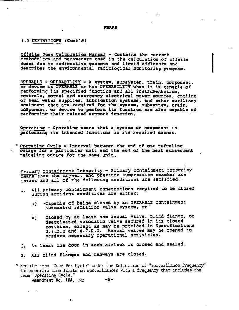
1.0 DEFINITIONS (Cont'd)
Offsite Dose Calculation Manual - Contains the current methodology and parameters used in the calculation of offsite doses due to radioactive gaseous and licuid effluents and describes the environmental radiological monitoring program.
OPERABLE - OPERABILITY - A system, subsystem, train, component, or device is OPERABLE or has OPERABILITY when it is capable of performing its specified function and all instrumentation, controls, normal and emergency electrical power sources, cooling or seal water supplies, lubrication systems, and other auxiliary equipment that are recuired for the system, subsystem, train, component, or device to perform its function are also capable of performing their related support function.
Operatinia- Operating means that a system or component is performing its intended functions in its required manner.
*Overatina Cycle - Interval between the end of one refueling
outage for a particular unit and the end of the next subsecuent "-efueling outage for the same unit.
Primary Containment Integrity - Primary containment integrity means tnat tne arywell and pressure suppression chamber are intact and all of the following conditions are satisfied:
1. All primary containment panetrations req-4ired to be Closed during accident conditions are either:
a) Capable of being closed by an OPE.ABLE containment autoaatic isolation valve system, or
b) Closed by at least one manual valve, blind flange, or deactivated autom,atic valve secured in its closed position, except as may be provided in Specificatio.s 3.7.D.2 and 4.7.D.2. Manual valves may be opened to perform necessary operational activities.
2. At least one door in each airlock is closed and sealed.
3. All blind flanges and manways are closed.
* See the term "Once Per Cycle" under the Definition of "Surveillance Frequency"
for specific time limits on surveillances with a frequency that includes the "term "Operating Cycle."
Amendment No. ;04, 182 -5-
4

PBAPS
1.0 DEFIN7TIONS (Cont'd)
Protective Action - An action initiated by the protection system when a limit is reached. A protective action can be at a channel or system level.
Protective Function - A system protective action which results from the protective action of the channels monitoring a particular plant condition.
Purge - Purgina - Purge or Purging is the controlled process of discharging air or gas from a confinement to maintain temperature, pressure, humidity, concentration or other operating condition, in such a manner that replacement air or gas is reauired to purify the confinement.
Rated Power - Rated power refers to operation at a reactor power of 3,293 MWt; this is also termed 100 percent power and is the maximum power level authorized by the operating license. Rated steam flow, rated coolant flow, rated neutron flux, and rated nuclear system pressure refer to the values of these parameters when the reactor is at rated power.
Reactor Power Operation - Reactor power operation is any operation with the mode switch in the *Startup" or "Run" position with the reactor critical and above 1% rated power.
Reactor Vessel Pressure - Unless otherwise indicated, reactor vessel pressures listed in the Technical Specifications are those measured by the reactor vessel steam space detectors.
Refuel Mode - With the mode switch in the refuel position, the reactor is shutdown and interlocks are established so that only one control rod may be withdrawn.
*•Refuelina Outage - Refueling outage is the period of time letween the shutdown of the unit prior to a refueling and the startup of the unit after that refueling. For the purpose of designatina freauency of testing and surveillance, a refueling outage shall mean a regularly scheduled outage; however, where such outages ocCur within 8 months of the completion of the previous refueling • See the term "Refuel" under the Definition of "Surveillance Frequency" for
specific time limits on surveillances with a frequency that includes the term "Re fueling..Outage."
Anipnadment No. 1JO, 182 - 6-

PBSPS Unit 3
1.0 DEFINITIONS (Cont'd)
Simulated Automatic Actuation - Simulated automatic actuation means applying a simulated signal to the sensor to actuate the circuit in question.
Site Boundary - That line beyond which the land is not owned, leased or otherwise controlled by licensee.
Source Check - A source check shall be the qualitative assessment of channel response when the channel sensor is exposed to a radioactive source.
Startup/Hot Standby Mode - In this mode the reactor protection scram trips, initiated by condenser low vacuum and'main steam line isolation valve closure are bypassed, the reactor protection system is energized with IRM neutron monitoring system trip, the APRM 15% high flux trip, and control rod withdrawal interlocks in service. This is often referred to as just Startup Mode. This is intended to imply the Startup/•ot Standby position of the mode switch.
Surveillance Frequency - Periodic surveillance tests, checks, calibrations, and examinations shall be performed within the specified surveillance intervals. Specified periodic surveillance intervals are defined as:
(N) Hours At least once per (N) hours Shiftly At least once per 12 hours Daily At least once per 24 hours (N) Days At least once per (N) days Twice Per Week At least once per 4 days Weekly At least once per 7 days (N) Weeks At least once per (70N) days Semi monthly At least once per 15 days Monthly At least once per 31 days 2 Month At least once per 61 days Quarterly or 3 month At least once per 92 days Semi-annually or 6 month At least once per 184 days Annually or 12 month At least once per 366 days Once Per Cycle At least once per 732 days 18 month At least once per 550 days Refuel At least once per 732 days (N) Years At least once per (3660) days (N) Refuel Cycle At least once per (7320) days 24 Months At least once per 732 days
These specified time intervals may be exceeded by 25%. Surveillance tests are not required on systems or parts of the systems that are not required to be operable or are tripped. If tests are missed on parts not required to be operable or are tripped, then they shall be performed prior to returning the system to an operable status.
A surveillance test of the diesel generators, that requires a plant outage, may be deferred beyond the calculated due date until the next refueling outage, provided the equipment has been similarly tested and meets the surveillance requirement for the other unit.
Transition Boilin - Transition boiling means the boiling regime between nucleate and film boilig. Transition boiling is the regime in which both nucleate and film boiling occur intermittently with neither type being completely stable.
Trip System - A trip system means an arrangement of instrument channel trip signals and auxiliary equipment required to initiate
-8- Amendment No. W0'A, 17i, 1•0, 170, I O0e

Unit 3
TABLE 4.1.2
REACTOR PROTECTION SYSTEM (SCRAM) INSTRUMENT CALIBRATION MINIMUM CALIBRATION FREQUENCIES FOR REACTOR PROTECTION INSTRUMENT CHANNELS
Instrument Channel
IRM High Flux
APRM High Flux Output Signal Flow Bias Signal
LPRM Signal
High Reactor Pressure
High Drywell Pressure
Reactor Low Water Level
High Water Level in Scram Discharge Instrument Volume
Turbine Condenser Low Vacuum
Main Steam Line Isolation Valve Closure
Main Steam Line High Radiation
Turbine First State Pressure Permissive
Group (1)
C
BI BI
BI
B2
B2
B2
A
B2
A
BI
A
Calibration (4)
Comparison to APRM on Controlled Shutdown
Heat Balance With Standard Pressure Source
TIP System Traverse
Standard Pressure Source
Standard Pressure Source
Pressure Standard
Water Column
Standard Vacuum Source
Note (5)
Standard Current Source (3)
Standard Pressure Source
Minimum Frequency (2)
Maximum frequency once per week.
Twice per week. Every eighteen months.
Every 6 weeks.
Once per operating cycle.
Once per operating cycle.
Once per operating cycle.
Every refueling outage.
Once per operating cycle.
Note (5)
Every 3 months.
Every 6 months.

Unit 3
TABLE 4.2.B (CONTINUED) MINIMUM TEST AND CALIBRATION FREQUENCY FOR CSCS
Instrument Channel
13) HPCI and RCIC Steam Line Low Pressure
14) HPCI Suction Source Levels
15) 4KV Emergency Power System Voltage Relays (HGA,SV)
16) ADS Relief Valves Bellows Pressure Switches
17) LPCI/Cross Connect Valve Position
18) Condensate Storage Tank Level (RCIC) (7)
19) 4KV Emergency Power Source Degraded Voltage Relays (IAV,CV-6.ITE)
rt
Instrument Functional lest
(1)
(1)
Once/operating cycle
Once/operating cycle
Once/refueling cycle
Once/3 months
Once/month
Calibration Frequency
Once/3 months
Once/3 months
Once/5 years
Once/operating cycle
N/A
Once/operating cycle
Once/eighteen months
Instrument Check
None
None
None
None
N/A
Once/day
None
!
!
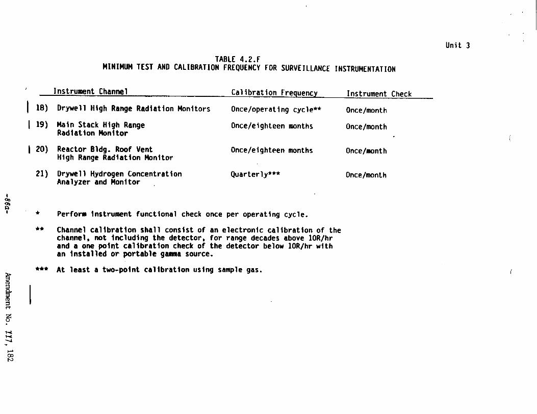
TABLE 4.2 F MINIMUM TEST AND CALIBRATION FREQUENCY FOR SURVEILLANCE INSTRUMENTATION
Instrument ChannelInstrument i t n ,.•nma.nr. -. I1 £h 1,, UIIIChane I,,IIIP.r
18) Drywell High Range Radiation Monitors
I 19) Main Stack High Range Radiation Monitor
S20) Reactor Bldg. Roof Vent High Range Radiation Monitor
21) Drywell Hydrogen Concentration Analyzer and Monitor
Once/operating cycle**
Once/eighteen months
Once/eighteen months
Quarterly***
Once/month
Once/month
Once/month
Once/month
* Perform instrument functional check once per operating cycle.
** Channel calibration shall consist of an electronic calibration of the channel, not Including the detector, for range decades above 1OR/hr and a one point calibration check of the detector below IOR/hr with an installed or portable gamma source.
* At least a two-point calibration using sample gas.
O0
"-o
Unit 3
I
Unit 3
PBAPS
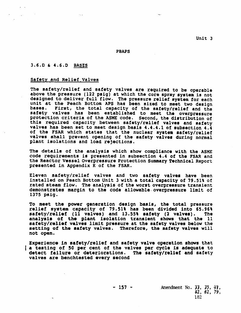
3.6.D & 4.6.D BASES
Safety and Relief Valves
The safety/relief and safety valves are required to be operable above the pressure (122 psig) at which the core spray system is not designed to deliver full flow. The pressure relief system for each unit at the Peach Bottom APS has been sized to meet two design bases. First, the total capacity of the safety/relief and the safety valves has been established to meet the overpressure protection criteria of the ASME code. Second, the distribution of this required capacity between safety/relief valves and safety valves has been set to meet design basis 4.4.4.1 of subsection 4.4 of the FSAR which states that the nuclear system safety/relief valves shall prevent opening of the safety valves during normal plant isolations and load rejections.
The details of the analysis which show compliance with the ASME code requirements is presented in subsection 4.4 of the FSAR and the Reactor Vessel Overpressure Protection Summary Technical Report presented in Appendix K of the FSAR.
Eleven safety/relief valves and two safety valves have been installed on Peach Bottom Unit 3 with a total capacity of 79.51% of rated steam flow. The analysis of the worst overpressure transient demonstrates margin to the code allowable. overpressure limit of 1375 psig.
To meet the power generation design basis, the total pressure relief system capacity of 79.51% has been divided into 65.96% safety/relief (11 valves) and 13.55% safety (2 valves). The analysis of the plant isolation transient shows that the 11 safety/relief valves limit pressure at the safety valves below the setting of the safety valves. Therefore, the safety valves will not open.
Experience in safety/relief and safety valve operation shows that a testing of 50 per cent of the valves per cycle is adequate to detect failure or deteriorations. The safety/relief and safety valves are benchtested every second
- 157 - Amendment No. •, •, Lf, 42, OZ, 79, 182

Unit 3
PBAPS
LIMITING CONDITIONS FOR OPERATION SURVEILLANCE REQUIREMENTS
3.7.A Primary Containment (Cont'd.) 4.7.A Primary Containment (Cont'd.)
f. Local leak rate tests (LLRT's) shall be performed on the primary containment testable penetrations and isolation valves in accordance with Tables 3.7.2, 3.7.3, & 3.7.4 at a pressure of 49.1 psig (except for the main steam isolation valves, see below) per 1OCFR5O Appendix J requirements. Bolted double-gasketed seals shall be tested whenever the seal is closed after being opened and at least once per operating cycrle, not to exceed the requirements of 1OCFR5O Apperdix J.
The Main Steamline isolation valves shall be tested at a pressure of 25 psig for leakage during each refueling outage, but in no case exceeding the requirements of IOCFR5O Appendix J. If a total leakage rate of 11.5 scf/hr for any one main steamline isolation valve is exceeded, repairs and retest shall be performed to correct the condition.
g. Continuous Leak Rate Monitor
When the primary containment is inerted, the containment shall be continuously monitored for gross leakage by review of the inerting system makeup requirements. This monitoring system may be taken out of service for maintenance but shall be returned to service as soon as practicable.
Amendment No.107,182-169-

It 3 -~ -* 'w"77
PBAPS
LIMITING CONDITIONS FOR OPERATION.. . . .,,, I £.. ,,,m• -. L , . I a LIIIGCNIIOSFROEAIO t-C~~r DC n~~.a~I
3.7.A Primary Containment (Cont'd.)
3. Pressure Suppression ChamberReactor Building Vacuum Breakers
a. Except as spedcfied in 3.7.A.3.b below, two pressure suppression chamber-reactor building vacuum breakers shall be operable at all times when primary containment integrity is required. The setpoint of the differential pressure instrumentation which actuates the pressure suppression chamber-reactor building vacuum breakers shall be 05 + 0.25 psid.
b. From and after tne date that one of the pressure suppression chamberreactor building vacuum breakers is made or found to be inoperable for any reason, reactor operation -is permissible only during the succeeding seven days unless such vacuum breaker is sooner made operable provided that the repair procedure does not violate primary containment integrity.
4. Drywell-Pressure Suppression Chamber Vacuum Breakers
a. When primary containment is required, all drywell-suppression chamber vacuum breakers shall be operable and positioned in the fully closed position (except during testing) except as specified in 3.7.A.4.b and c below.
b. Drywell-suppression chamber vacuum breaker(s) may be "not fully seated" as shown by position indication if testing confirms that the bypass area is less than or equivalent to a one-inch diameter hole. Testing shall be initiated witting 8 hours of initial detection of a "not fully seated" position
4.7.A Primary Containment (Cont'd.)
h. Drvwell Surfaces
The interior surfaces of the drywell and torus shall be visually inspected each operating cycle for evidence of deterioration. In addition, the external surfaces of the torus below the water level shall be inspected on a routine basis for evidence of torus corrosion or leakage.
3. Pressure Suppression ChamberReactor Building Vacuum Breakers
a. The pressure suppression chamberreactor building vacuum breakers shall be checked for proper operation every refueling outage. Associated instrumentation including setpoint shall be checked for proper operation every eighteen months.
4. Orywell-Pressure Suppression Chamber vacuum Breakers
a. Each drywell-suppression chamber vaccuum breaker shall be exercised through an openingclosing cycle once a month.
b. When it is determined that a vacuum breaker is inoperable for opening at a time when operability is required, all other operable vacuum breakers shall be exercised immediately and every 15 days thereafter until the inoperable vacuum breaker has been returned to normal service.
c. Once per operating cycle each vacuum breaker shall be visually inspected
Amendment No. ZM, Ul0, 107,182-170-

Unit 3
LIMITING CONDITIONS FOR OPERATION SURVEILLANCE REQUIREMENTS
3. If any reactor instrumentation line excess flow check valve is inoperable, within 4 hours either:
a. Restore the inoperable excess flow check valve to operable status or,
b. Isolate the instrument line and declare the associated instrument inoperable.
c. Otherwise be in at least Hot Shutdown within the next 12 hours and in Cold Shutdown within the following 24 hours.
3.7.E Large Primary Containment Purge/Vent Isolation Valves
1. The large primary containment purge/vent isolation valves (6 and 18 inches) shall be operated in accorddnce with specification 3.7.D and with specifications 3.?.E.2 and 3.7.E.3 below.
2. When the reactor pressure is greater than 100 psig, and the reactor critical, and the reactor mode switch in the "Startup" or "Run" mode, primary containment purging or venting shall be subject to the following restrictions:
a. The large prilmiry containment purge/vent isolation valves may be opened only for inerting, de-inerting, and pressure control.
b. The accumulated time a purge or vent flow path exists shall be limited to 90 hours per calendar year.
3. At least once per operating cycle the operability of the reactor coolant system instrument line flow check valves shall be verified.
4.7.E Large Primary Containment Purge/Vent Isolation Valves
1. The inflatable seals for the large containment ventilation isolation valves shall be replaced at least once every second refueling outage.
2. The LLPT leak rate for the large containment ventilation isolation valves shall be compared to the previously measured leak rate to detect excessive valve degradation.
Amendment No. 140, 182
PBAPS
-178-

Unit 3
PBAPS
NOTES FOR TABLES 3.7.2 THROUGH 3.7.4
(1) Minimum test duration for all valves and penetrations listed is one hour.
(2) Test pressures of at least 49.1 psig for all valves and penetrations except MSIV's which are tested at 25 psig.
(3) MSIV's acceptable leakage is 11.5 scfh/valve of air.
(4) The total acceptable leakage for all valves and penetrations other than the MSIV's is 0.60 La.
(5) Local leak tests on all testable isolation valves shall be performed per 10CFR50, Appendix J requirements.
(6) Local leak tests on all testable penetrations shall be
performed per 10CFR50, Appendix J requirements.
(7) Personnel Air Locks shall be tested at 6-month intervals.
(8) The personnel air locks are tested at 49.1 psig.
(9) Identifies isolation valves that may be tested by applying pressure between the inboard and outboard valves.
(10) Gate valves are tested in reverse direction. Test acceptable since the normal force between the seat and the disc generated by stem action alone is greater than ten (10) times the normal force induced by test differential pressure except for valves MO-10-31A,B which is 7.97. This applies to the following valves:
MO-2-74 MO-10-31A, B MO-13-15 M0-10-18 MO-23-15 MO-12-15 (Unit #2) MO-10-32 (Unit #2)
Amendment No. 29, 107, 182-188-

Unit 3
PBAPS
3.7.A & 4.7.A BASES (Cont'd.)
The design basis loss-of-coolant accident was evaluated at the primary containment maximum allowable accident leak rate of 0.5%/day at 56 psig. Calculations made by the AEC staff with leak rate and a standby gas treatment system filter efficiency of 90% for halogens and assuming the fission product release fractions stated in TID 14844, show that the maximum total whole body passing cloud dose is about 1.0 REM and the maximum total thyroid dose is about 14 REM at, 4500 meters from the stack over an exposure duration of two hours. The resultant doses that would occur for the duration of the accident at the low population zone distance of 7300 meters are about 2.5 REM total whole body and 105 REM total thyroid. Thus, the doses reported are the maximum that would be expected in the unlikely event of a design basis loss-of-coolant accident. These doses are also based on the assumption of no holdup in the secondary containment resulting in a direct release of fission products from the primary containment through the filters and stack to the environs. Therefore, the specified primary containment leak rate and filter efficiency are conservative and provide margin between expected off-site doses and 10 CFR 100 guidelines.
The water in the suppression chamber is used only for cooling in the event of an accident; i.e., it is not used for normal operation; therefore, a daily check of the temperature and volume is adequate to assure that adequate heat removal capability is present.
Drywell Interior
The interiors of the drywell and suppression chamber are painted to prevent rusting. The inspection of the paint during each major refueling outage, assures the paint is intact. Experience with this type of paint at fossil fueled generating stations indicates that the inspection interval is adequate.
Post LOCA Atmosphere Dilution
In order to ensure that the containment atmosphere remains inerted, i.e. the oxygen-hydrogen mixture below the flamable limit, the capability to inject nitrogen into the containment after a LOCA is provided. During the first year of operation the normal inerting nitrogen makeup system will be available for this purpose. After that time the specifically designed CAD system will serve as the post-LOCA Containment Atmosphere Dilution System. By maintaining a minimum of 2000 gallons of liquid N2 in the storage tank it is assured that a seven-day supply of N. for post-LOCA containment inerting is available. Since the inerting makeup system is continually functioning, no
Amendment No. 182- 193 -

PBAPS
LTNTT1Nt� CONDITIONS FOR OPFRATION SURVFT[IANCF 3F(uITQFWMT�
and one main stack noble gas monitor shall be operable and set to alarm in accordance with the methodology and parameters in the ODCM. From and after the date that both reactor building exhaust vent monitors or both main stack noble gas monitors are made or found to be Inoperable for any reason, effluent releases via their respective pathway may continue provided at least two independent grab samples are taken at least once per 8 hrs. and these samples are analyzed for gross activity within 24 hours, and at least two technically qualified members of the facility staff independently verify the release rate calculations.
c. One reactor building exhaust vent iodine filter and one main stack iodine filter and one reactor building exhaust vent particulate filter and one main stack particulate filter with their respective flow rate monitors shall be operable. From and after the date that all iodine filters or all particulate filters for either the reactor building exhaust vent monitor or the main stack monitor are made or found to be inoperable for any reason, effluent releases via their respective pathway may
shall also demonstrate that control room alarm annunciation occurs if any of the following conditions exist: 1. Instrument indicates
measured levels above the alarm setpoint.
2. Instrument indicates a downscale failure.
Additionally, an instrument check shall be performed every day.
4b. The reactor building exhaust vent and the main stack flow rate monitors shall be calibrated every 12 months. Additionally, an instrument check shall be performed every day.
4c. The reactor building exhaust vent and the main stack iodine and particulate sample flow rate monitors shall be calibrated every 12 months. Additionally, an instrument check shall be performed every day for the reactor building exhaust vent sample flow rate monitors, and every week for the main stack sample flow rate monitor.
4d. The main stack sample flow line Hi/o pressure switches shall be functionally tested every 6 months and calibrated every 24 months.
Amendment No. 104, 119, 182
Unit 3
ITMTTINr. MHOITIONS FOR OPERATION qURVE I I I Auff RMITRMIM
-211-

LIMITING CONDITIONS FOR OPERATION
Unit 3PBAPS
SURVEILLANCE REQUIREMENTS
3.9 AUXILIARY ELECTRICAL SYSTEM 4
Applicability:
Applies to the auxiliary electrical power system.
Objective:
To assure an adequate supply of electrical power for operation of those systems required for safety.
Specification:
A. Auxiliary Electrical A Equipment
The reactor shall not be made critical unless all of the following conditions are satisfied:
1. Two physically independent circuits between the offsite transmission network and the onsite Class 1E distribution system are operable.
2. The four diesel generators shall be operable and there shall be a mimimum of 108,000 gallons of diesel fuel on site. Each operable diesel generator shall have:
a. A separate day tank containing a minimum of 200 gallons of fuel,
b. A separate fuel storage tank with a minimum of 28,000 gallons of fuel, an'
c. A separate fuel transfer pump.
3. The unit 4kV emergency buses and the 480V emergency load centers are energized.
4. The four unit 125V batteries and their chargers shall be operable.
.9 AUXILIARY ELECTRICAL SYSTEM
Applicability
Applies to the periodic testing requirements of the auxiliary electrical systems.
Objective:
Verify the operability of the auxiliary electrical system.
Specification:
Auxiliary Electrical Equipment
. Diesel Generators and Offsite Circuits
1. Each of the required independent circuits between the offsite transmission network and the onsite Class 1E distribution system shall be:
a. Verified OPERABLE at least cnce per 7 days by verifying correct breaker alignments and indicated power availaoility.
b. Demonstrated OPERABLE at least once per 24 months by transferring, manually and automatically, the start-up source from the normal circuit to the alternate circuit.
Amendment No. MZ, 170, 182
I
-217-
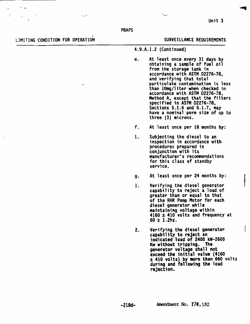
Unit 3
PBAPS
LIMITING CONDITION FOR OPERATION SURVEILLANCE REQUIREMENTS
4.9.A.1.2 (Continued)
e. At least once every 31 days by obtaining a sample of fuel oil from the storage tank in accordance with ASTM 02276-78, and verifying that total particulate contamination is less than 10mg/liter when checked in accordance with ASTM 02276-78, Method A, except that the filters specified in ASTH D2276-78, Sections 5.1.6 and 5.1.7, may have a nominal pore size of up to three (3) microns.
f. At least once per 18 months by:
1. Subjecting the diesel to an inspection in accordance with procedures prepared in conjunction with its manufacturer's recommendations for this class of standby service.
g. At least once per 24 months by:
1. Verifying the diesel generator capability to reject a load of greater than or equal to that of the RHR Pump Motor for each diesel generator while maintaining voltage within 4160 ± 410 volts and frequency at 60 ± 1.2hz.
2. Verifying the diesel generator capability to reject an indicated load of 2400 kW-2600 Kw without tripping. The generator voltage shall not exceed the initial value (4160 ± 410 volts) by more than 660 volts during and following the load rejection.
Amendment No. 170,182-218d-

Unit 3
PBAPS LIMITING CONDITIONS FOR OPERATION SURVEILLANCE REQUIREMENTS
4.9.A.1.2.g (Continued)
3. Verifying that all automatic diesel generator trips except engine overspeed, generator differential over-current, generator ground overcurrent and manual cardox initiation are automatically bypassed upon an ECCS actuation signal.
4. Verifying the diesel generator operates for at least 24 hours. During the first 2 hours of this test, the diesel generator shall be loaged to an indicated 2800-3000 kW and during the remaining 22 hours of this test, the diesel generator shall be loaged to an indicated 2400-2600 kW .
5. Verifying diesel generator capability at full load temperature within 5 minutes after completing the 24 hour testc by starting and loading the diesel as described in Surveillance Requirement 4.9.A.1.2.b and operatIng for greater than 5 minutes
aThis test shall be conducted in accordance with the manufacturer's recommendations regarding engine prelube and warm-up and, as applicable, loading and shutdown.
bThis band is meant as guidance to avoid routine overloading of the engine. Loads in excess of this band for special testing, under direct monitoring by the manufacturer or system engineer, or momentary variations due to changing bus loads shall not invalidate the test.
Clf Surveillance Requirement 4.9.A.1.2.g.5 is not satisfactorily completed, it is not necessary to repeat the preceding 24-hour test. Instead, the diesel generator may be operated at 2400-2600 kW for 1 hour or until operating temperature has stabilized prior to performing Surveillance Requirement 4.9.A.1.2.g.5.
dPerformance of Surveillance Requirement 4.9.A.1.2.g.5 will not be used to satisfy the requirements of Surveillance Requirement 4.9.A.1.2.b.
Amendment No. 170, 182_91 Q&_

Unit 3P BA PSLIMITING CONDITIONS FOR OPERATION SURVEILLANCE REQUIREMENTS
4.9.A.1.2 (Continued)
6. Verifying that the fuel transfer pump transfers fuel from each fuel storage tank to the day tank of each diesel via the installed cross connection lines.
h. At least once each operating cycle by:
1. Simulating a loss-of-offsite power by itself, and:
a) Verifying deenergization of the emergency busses and load shedding tr(', the emergency busses.
b) Verifying the dilsel generator starts on the auto-start signal, energizes the emergency busses within 10 seconds, energizes the permanent and auto-connected loads through the individual load timers and operates for greater than or equal to 5 minutes.
After energization, the steady-state voltage and frequency of the emergency busses shall be maintained at 4160 + 410 volts and 60 + 1.2 Hz during this test.
aThis test shall be conducted in accordance with the manufacturer's recommendations regarding engine prelube and warm-up and, as applicable, loading and shutdown.
Amendment No. 170,182-218f -

Unit 3
PBAPS
LIMITING CONDITIONS FOR OPERATION SURVEILLANCE REQUIREMENTS
4.9.A.1.2 (Continued)
4. Verifying the diesel generator's capability to:
a) Synchronize with the offsite power source while the generator is loaded with its emergency loads upon a simulated restoration of offsite power.
b) Transfer its loads to the offsite power source, and
c) Be restored to its standby status.
i. At least once per 10 years or after any modifications which could affect diesel generator interdependence by starting" all four diesel generators simultaneously and verifying that all four diesel generators accelerate to at least 855 rpm in less than or equal to 10 seconds.
j. At least once per 10 years by draining each fuel oil tank, removing the accumulated sediment and cleaning the tank using a sodium hypochlorite or equivalent solution.
k. The fuel oil storage tank cathodic protection system shall be checked as follows:
1. At least once every twelve months perform a test to determine whether the cathodic protection is adequate, and
'This test shall be conducted in accordance with the manufacturer's recommendations regarding engine prelube and warmup and, as applicable, loading and shutdown.
Amendment No. 170,182-218h-
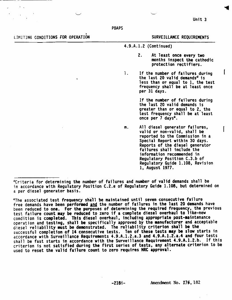
Unit 3
PBAPS
LIMITING CONDITIONS FOR OPERATION SURVEILLANCE REQUIREMENTS
4.9.A.1.2 (Continued)
2. At least once every two months inspect the cathodic protection rectifiers.
1. If the number of failures during the last 20 valid demandsd is less than or equal to 1, the test frequency shall be at least once per 31 days.
If the number of failures during the last 20 valid demands is greater than or equal to 2, the test frequency shall be at least once per 7 days*.
m. All diesel generator failures, valid or non-valid, shall be reported to the Commission in a Special Report within 30 days. Reports of the diesel generator failures shall include the information recommended in Regulatory Position C.3.b of Regulatory Guide 1.108, Revision 1, August 1977.
"dCriteria for determining the number of failures and number of valid demands shall be
in accordance with Regulatory Position C.2.e of Regulatory Guide 1.108, but determined on a per diesel generator basis.
eThe associated test frequency shall be maintained until seven consecutive failure free demands have been performed and the number of failures in the last 20 demands have been reduced to one. For the purposes of determining the required frequency, the previous test failure count may be reduced to zero if a complete diesel overhaul to like-new condition is completed. This diesel overhaul, including appropriate post-maintenance operation and testing, shall be specifically approved by the manufacturer and acceptable diesel reliability must be demonstrated. The reliability criterion shall be the successful completion of 14 consecutive tests. Ten of these tests may be slow starts in accordance with Surveillance Requirements 4.9.A.1.2.a.3 and 4.9.A.1.2.a.4 and four tests shall be fast starts in accordance with the Surveillance Requirement 4.9.A.1.2.b. If this criterion is not satisfied during the first series of tests, any alternate criterion to be used to reset the valid failure count to zero requires NRC approval.
Amendment No. 170, 182-2181-
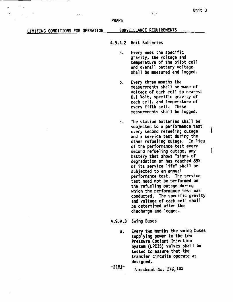
Unit 3
PBAPS
LIMITING CONDITIONS FOR OPERATION SURVEILLANCE REQUIREMENTS
4.9.A.2 Unit Batteries
a. Every week the specific gravity, the voltage and temperature of the pilot cell and overall battery voltage shall be measured and logged.
b. Every three months the measurements shall be made of voltage of each cell to nearest 0.1 Volt, specific gravity of each cell, and temperature of every fifth cell. These measurements shall be logged.
c. The station batteries shall be subjected to a performance test every second refueling outage and a service test during the other refueling outage. In lieu of the performance test every second refueling outage, any battery that shows "signs of degradation or has reached 85% of its service life" shall be subjected to an annual performance test. The service test need not be performed on the refueling outage during which the performance test was conducted. The specific gravity and voltage of each cell shall be determined after the discharge and logged.
4.9.A.3 Swing Buses
a. Every two months the swing buses supplying power to the Low Pressure Coolant Injection System (LPCIS) valves shall be tested to assure that the transfer circuits operate as designed.
-218j- Amendment No. 170,182

LIMITTING CONDITIONS FOR OPERATION SURVE I LLANCE REQU I REMENTS
4. 11.0.3
Visual inspection of snubbers required to be operable under the provisions of 3.11.0.1 shall verify that 1) there are no indications of damage or impaired operability, 2) attachments to the foundations or supporting structure are functional, and 3) fasteners for the attachment of the snubber to the component and to the snubber anchorage are functional.
Snubbers which appear to be inoperable as a result of visual inspections shall be classified as unacceptable and may be reclassified acceptable for the purpose of establishing the next visual inspection interval, providing that 1) the cause of the rejection is clearly established and remedied for that particular snubber and for other generically susceptible snubbers; and 2) the affected snubber is functionally tested in the as found condition and determined operable per Specification 4.11.0.7 or 4.11.0.8, as applicable. All snubbers found connected to an inoperable comon hydraulic fluid reservoir shall be counted as unacceptable for determining the next inspection interval. A review and evaluation shall be performed and documented to justify continued operation with an unacceptable snubber. If continued operation cannot be justified, the snubber shall be declared inoperable and the Limiting Conditions for Operation shall be met.
4.11.0.4
Functional Test
*Performance of 4.11.D.4(a) with an operating cycle of 732 days is approved for the operating cycle following refueling outage 3R09 only.
• a) Once each operating cycle, during shutdown, a representative sample of 10% of each type of (mechanical or hydraulic) snubber required to be operable under the provisions of 3.11.0.1 shall be functionally tested either in place or in a bench test. For every unit found to be inoperable an additional 10% of that type of snubber shall be functionally tested until no more failures are found or all snubbers of that type have been tested. The functional test requirements for mechanical
912Ak. Amendment -No. -- L X1%,182 1
Unit 3
4.11.0.3
Visual inspection of snubbers
required to
be operable under
the provisions
of
3.11.9.1 shall
verify that
1) there are
no and|cations
of damage or lmpatred
operability,
2) attachments
to the
foundations
or supporting
structure
are
functional,
and 3)
fasteners
for the
attachment
of the
snubber
to the
component
and to
the snubber
anchorage
are
functional.
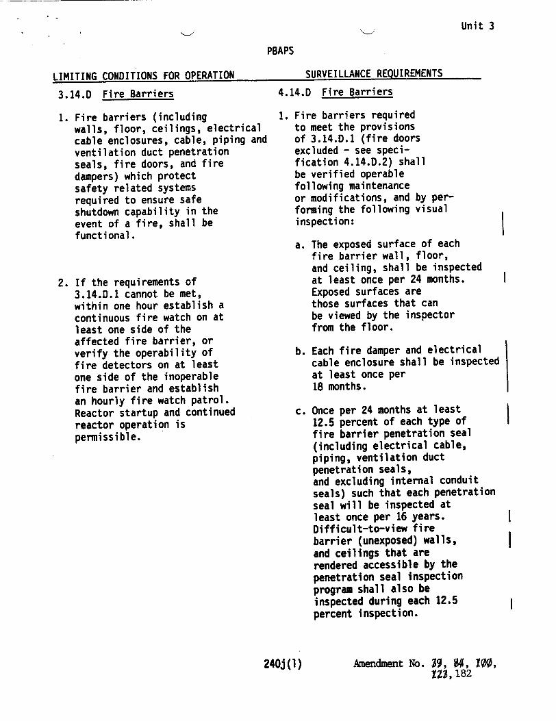
Unit 3
PBAPS
I TMTTTN1• rONfnTTONN FOR OPERATION SURVEILLANCE REQUIREMENTS
3.14.D Fire Barriers
1. Fire barriers (including walls, floor, ceilings, electrical cable enclosures, cable, piping and ventilation duct penetration seals, fire doors, and fire dampers) which protect safety related systems required to ensure safe shutdown capability in the event of a fire, shall be functional.
2. If the requirements of 3.14.D.1 cannot be met, within one hour establish a continuous fire watch on at least one side of the affected fire barrier, or verify the operability of fire detectors on at least one side of the inoperable fire barrier and establish an hourly fire watch patrol. Reactor startup and continued reactor operation is permissible.
4.14.D Fire Barriers
1. Fire barriers required to meet the provisions of 3.14.D.1 (fire doors excluded - see specification 4.14.D.2) shall be verified operable following maintenance or modifications, and by performing the following visual inspection:
a. The exposed surface of each fire barrier wall, floor, and ceiling, shall be inspected at least once per 24 months. Exposed surfaces are those surfaces that can be viewed by the inspector from the floor.
b. Each fire damper and electrical cable enclosure shall be inspected at least once per 18 months.
c. Once per 24 months at least 12.5 percent of each type of fire barrier penetration seal (including electrical cable, piping, ventilation duct penetration seals, and excluding internal conduit seals) such that each penetration seal will be inspected at least once per 16 years. Difficult-to-view fire barrier (unexposed) walls, and ceilings that are rendered accessible by the penetration seal inspection program shall also be inspected during each 12.5 percent inspection.
240j (1) Amendment No. 9, $4, 100, SZ3,182
ITMTTTur. rnmn1T7nN4z FnR OPERATION
l

Unit 3 %PAPS
LIMITING CONDITIONS FOR OPERATION SURVEILLANCE REQUIREMENTS
4.14.D Fire Barriers (Cont'd)
1. (Continued)
If any penetration seal selected for inspection is found by surveillance requirements 4.14.D.1(c) in a condition which may compromise the operability of the penetration seal, the cause shall be evaluated. If the cause is a failure to adhere to penetration seal procedures, or an identified phenomenon (e.g., physical interference), the cause shall be corrected and potentially affected seals inspected. Otherwise, a visual inspection of an additional 12.5 percent, selection based on the nature of the degradation, shall be made. This inspection process shall continue until a 12.5 percent sample with no degradation is found.
2. Fire doors required to meet the provisions of 3.14.0.1 shall be verified operable by inspecting the closing mechanism and latches every 6 months*, and by verifying:
a. The operability of the fire door supervision system for each electrically supervised fire door by performing a functional test every month.
b. That each locked-closed fire door is in the closed position every week.
c. That each unlocked fire door without electrical supervision is in the closed position every day.
* Fire door inspections requiring access to radiation areas may be deferred until the next refueling outage or shutdown initially expected to be of at least a 7-day duration.
Amendment No. $9, ", 100, ZZ, 182240i (2)
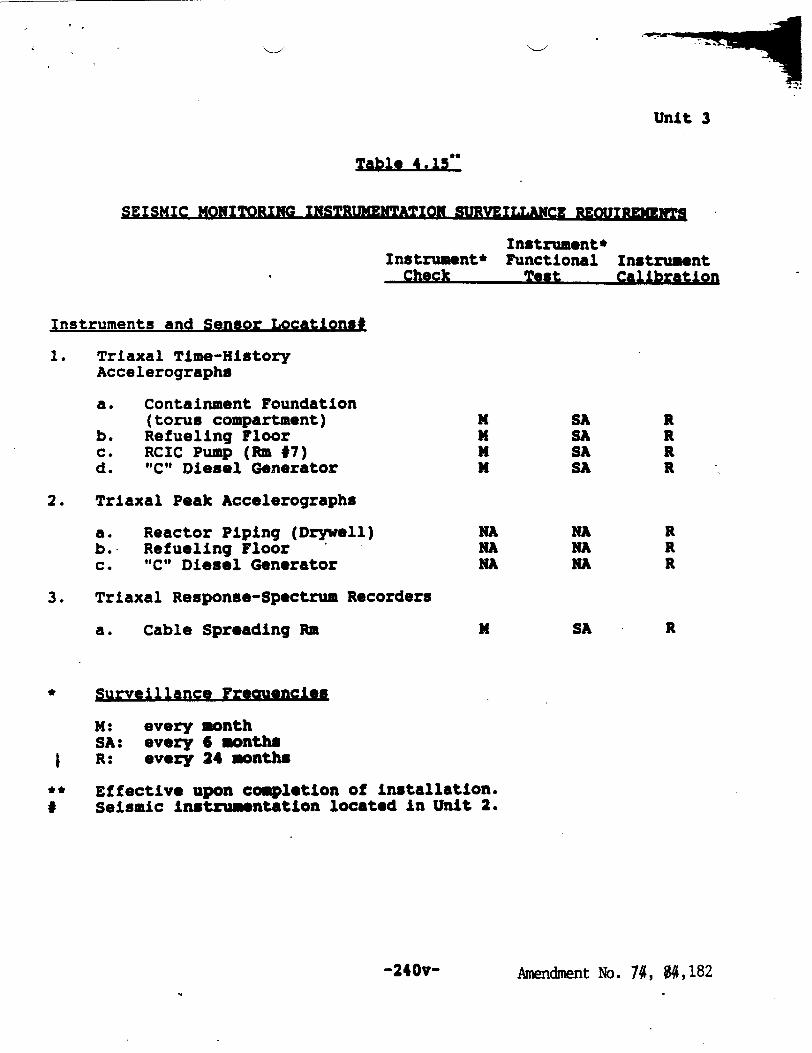
Unit 3
SEISMIC MONITORING INSTRUMENTATION SURVEILLANCE REOUIREMENTS
Instrument* Instrument* Functional Instrument
Check Test Calibration
Instruments and Sensor Locations#
1. Triaxal Time-History Accelerographs
a. Containment Foundation (torus compartment) 1 SA R
b. Refueling Floor S SA R c. RCIC Pump (Rm 7) N SA R d. "C" Diesel Generator x SA R
2. Triaxal Peak Accelerographs
a. Reactor Piping (Drywell) NA NA R b. Refueling Floor NA NA R c. "C" Diesel Generator NA NA R
3. Triaxal Response-Spectrum Recorders
a. Cable Spreading Ra N SA R
* Surveillance Freauencies
M1: every month SA: every 6 months R: every 24 months
** Effective upon completion of installation. # Seismic instrumentation located in Unit 2.
Amendment No. 74, M, 182-240v-
UNITED STATES S P NUCLEAR REGULATORY COMMISSION
u 3 WASHINGTON, D. C. 20555
SAFETY EVALUATION BY THE OFFICE OF NUCLEAR REACTOR REGULATION
RELATED TO AMENDMENT NOS. 1 7 9 AND 182 TO FACILITY OPERATING
LICENSE NOS. DPR-44 and DPR-56
PHILADELPHIA ELECTRIC COMPANY PUBLIC SERVICE ELECTRIC AND GAS COMPANY
DELMARVA POWER AND LIGHT COMPANY ATLANTIC CITY ELECTRIC COMPANY
PEACH BOTTOM ATOMIC POWER STATION, UNIT NOS. 2 AND 3
DOCKET NOS. 50-277 AND 50-278
1.0 INTRODUCTION
By letters dated September 28, 1992 and October 19, 1992, as supplemented by letters dated March 16, 1993, April 13, 1993, May 28, 1993, June 7, 1993, June 23, 1993, July 1, 1993 and July 7, 1993, the Philadelphia Electric Company, (PECo, the licensee) submitted a request for changes to the Peach Bottom Atomic Power Station, Unit Nos. 2 and 3, Technical Specifications (TS). The requested changes extend the interval for certain Technical Specification surveillance requirements to 24 months with an additional 25-percent grace period. The proposed extension of the interval was accomplished for some surveillances by explicitly embedding the term 24 months in the particular line item requirement. For other surveillances, the proposed extension was accomplished by changing the TS Section 1.0 definition of operating cycle or refueling cycle to a maximum of 732 days. A 25-percent grace period beyond the 732 days is still allowed.
Generic Letter 91-04 provides generic guidance to support the development of TS revisions to allow a 24-month fuel cycle and includes requirements to evaluate the effect on safety for an increase in surveillance intervals to accommodate a 24-month fuel cycle. The licensee's evaluation should conclude that the net effect on safety is small, that historical plant maintenance and surveillance data support the proposed extended surveillance interval, and that the assumptions of the plant licensing basis are still bounding with the incorporation of a 24-month surveillance interval.
The licensee concluded in the October 19, 1992, submittal, that the assumptions of the plant licensing basis are not impacted by the proposed changes. The licensee's conclusion on the impact of the prposed changes on system availability and safety and the bases for those conclusios are described in Section 2.0 of this safety evaluation.
9308240320 930802 PDR ADOCK 05000277 P PDR
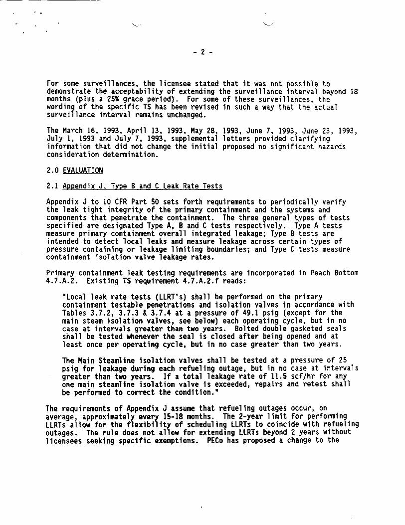
-2-
For some surveillances, the licensee stated that it was not possible to demonstrate the acceptability of extending the surveillance interval beyond 18 months (plus a 25% grace period). For some of these surveillances, the wording of the specific TS has been revised in such a way that the actual surveillance interval remains unchanged.
The March 16, 1993, April 13, 1993, May 28, 1993, June 7, 1993, June 23, 1993, July 1, 1993 and July 7, 1993, supplemental letters provided clarifying information that did not change the initial proposed no significant hazards consideration determination.
2.0 EVALUATION
2.1 Appendix J. Type B and C Leak Rate Tests
Appendix J to 10 CFR Part 50 sets forth requirements to periodically verify the leak tight integrity of the primary containment and the systems and components that penetrate the containment. The three general types of tests specified are designated Type A, B and C tests respectively. Type A tests measure primary containment overall integrated leakage; Type B tests are intended to detect local leaks and measure leakage across certain types of pressure containing or leakage limiting boundaries; and Type C tests measure containment isolation valve leakage rates.
Primary containment leak testing requirements are incorporated in Peach Bottom
4.7.A.2. Existing TS requirement 4.7.A.2.f reads:
"Local leak rate tests (LLRT's) shall be performed on the primary containment testable penetrations and isolation valves in accordance with Tables 3.7.2, 3.7.3 & 3.7.4 at a pressure of 49.1 psig (except for the main steam isolation valves, see below) each operating cycle, but in no case at intervals greater than two years. Bolted double gasketed seals shall be tested whenever the seal is closed after being opened and at least once per operating cycle, but in no case greater than two years.
The Main Steamline isolation valves shall be tested at a pressure of 25 psig for leakage during each refueling outage, but in no case at intervals greater than two years. If a total leakage rate of 11.5 scf/hr for any one main steamline isolation valve is exceeded, repairs and retest shall be performed to correct the condition."
The requirements of Appendix J assume that refueling outages occur, on average, approximately every 15-18 months. The 2-year limit for performing LLRTs allow for the flexibility of scheduling LLRTs to coincide with refueling outages. The rule does not allow for extending LLRTs beyond 2 years without licensees seeking specific exemptions. PECo has proposed a change to the

-3
wording of TS 4.7.A.2.f to state specifically that the surveillance test interval for LLRTs is governed by Appendix J to 10 CFR Part 50. The proposed wording is as follows:
"Local leak rate tests (LLRT's) shall be performed on the primary containment testable penetrations and isolation valves in accordance with Tables 3.7.2, 3.7.3 & 3.7.4 at a pressure of 49.1 psig (except for the main steam isolation valves, see below) per 10 CFR 50 Appendix J requirements. Bolted double gasketed seals shall be tested whenever the seal is closed after being opened and at least once per operating cycle, not to exceed the requirements of 10 CFR 50 Appendix J.
The Main Steamline isolation valves shall be tested at a pressure of 25 psig for leakage during each refueling outage, but in no case exceeding the requirements of 10 CFR 50 Appendix J. If a total leakage rate of 11.5 scf/hr for any one main steamline isolation valve is exceeded, repairs and retest shall be performed to correct the condition."
TS Tables 3.7.2, 3.7.3 and 3.7.4 list all of the testable penetrations and isolation valves in the facility. The tables have accompanying notes (5) and (6) which specify a leak rate test interval of no greater than two years for each penetration or valve. The licensee proposed to revise the notes to specifically reference the requirements of Appendix J.
The staff reviewed the proposed changes. The revised wording of TS 4.7.A.2.f and TS Tables 3.7.2, 3.7.3 and 3.7.4, notes (5) and (6) is consistent with the requirements of 10 CFR Part 50, Appendix J. The proposed wording changes are administrative in nature; they do not change the actual testing requirements. Therefore, the staff finds the proposed changes acceptable.
2.2 Fire Protection and Fire Detection
Peach Bottom has numerous fire prevention, detection and mitigation features installed as part of the fire protection program. The PBAPS fire protection program is designed to provide reasonable assurance that a fire will not prevent the performance of necessary safe shutdown functions. The fire protection program includes surveillance requirements on certain installed detection, prevention and mitigation features.
2.2.1 Fire Barriers
Existing TS 4.14.D.1 imposes surveillance requirements on certain types of fire barriers. The fire barriers which are visually inspected to verify operability once per 18 months include: a) exposed surfaces of barriers and cable enclosures; b) each fire damper; and c) at least 10 percent of each type of fire barrier penetration seal such that each penetration seal will be inspected at least once per 15 years.
The licensee proposed to revise TS 4.14.D.1 as follows:
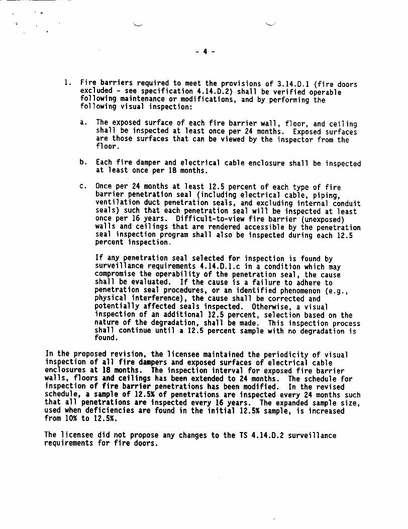
- 4
1. Fire barriers required to meet the provisions of 3.14.D.1 (fire doors excluded - see specification 4.14.D.2) shall be verified operable following maintenance or modifications, and by performing the following visual inspection:
a. The exposed surface of each fire barrier wall, floor, and ceiling shall be inspected at least once per 24 months. Exposed surfaces are those surfaces that can be viewed by the inspector from the floor.
b. Each fire damper and electrical cable enclosure shall be inspected at least once per 18 months.
c. Once per 24 months at least 12.5 percent of each type of fire barrier penetration seal (including electrical cable, piping, ventilation duct penetration seals, and excluding internal conduit seals) such that each penetration seal will be inspected at least once per 16 years. Difficult-to-view fire barrier (unexposed) walls and ceilings that are rendered accessible by the penetration seal inspection program shall also be inspected during each 12.5 percent inspection.
If any penetration seal selected for inspection is found by surveillance requirements 4.14.Do.1c in a condition which may compromise the operability of the penetration seal, the cause shall be evaluated. If the cause is a failure to adhere to penetration seal procedures, or an identified phenomenon (e.g., physical interference), the cause shall be corrected and potentially affected seals inspected. Otherwise, a visual inspection of an additional 12.5 percent, selection based on the nature of the degradation, shall be made. This inspection process shall continue until a 12.5 percent sample with no degradation is found.
In the proposed revision, the licensee maintained the periodicity of visual inspection of all fire dampers and exposed surfaces of electrical cable enclosures at 18 months. The inspection interval for exposed fire barrier walls, floors and ceilings has been extended to 24 months. The schedule for inspection of fire barrier penetrations has been modified. In the revised schedule, a sample of 12.5% of penetrations are inspected every 24 months such that all penetrations are inspected every 16 years. The expanded sample size, used when deficiencies are found in the initial 12.5% sample, is increased from 10% to 12.5%.
The licensee did not propose any changes to the TS 4.14.D.2 surveillance requirements for fire doors.
I .
-5-
The licensee concluded that the impact of extending the TS 4.14.D.1 surveillance requirements for the fire barriers on reliability and availability is small because the fire protection program is formulated such that the failure of an active or passive component in one of the fire protection features is backed up by another entirely different fire protection feature (e.g. fire barriers, sprinklers, detection). The licensee confirmed that historical plant maintenance and surveillance data do not invalidate this conclusion.
The staff reviewed the information presented by the licensee and concluded that the proposed changes do not have a significant effect on safety and follow the guidance of Generic Letter (GL) 91-04. Therefore, the proposed changes to TS 4.14.D.1 are acceptable.
2.2.2 Fire Detectors
Existing TS 4.14.C imposes the surveillance requirements for fire detectors. Smoke and heat detectors that are inaccessible due to high radiation or an inerted atmosphere are required to be functionally tested once per refueling outage per TS 4.14.C.2 to ensure that the detector circuitry has not degraded to an unacceptable level of performance. These detectors are required during all modes of operation. The licensee proposed to increase the maximum surveillance interval for the functional test in 4.14.C.2 by changing the definition of refueling cycle from a maximum of 550 days with a 25% grace period to 732 days with a 25% grace period.
The licensee stated that the detectors are of a "Class-B" type installation; the detectors are electrically supervised to detect ground fault, circuit breaks, or power failures. Because of this supervision, the licensee concluded that the impact, if any, on system availability is small as a result of this change to TS 4.14.C.2. The licensee confirmed that historical plant maintenance and surveillance data do not invalidate this conclusion. The staff reviewed the information presented by the licensee and concluded that the proposed changes do not have a significant effect on safety and follow the guidance of GL 91-04. Therefore, the proposed changes are acceptable.
2.3 Main Control Room Emergency Ventilation System (MCREVS)
The MCREVS Is designed to provide a suitable environment for continuous personnel occupancy and ensures the operability of control room equipment and instruments under accident conditions. The system consists of two redundant supply fans, redundant high efficiency particulate air (HEPA) filter trains, and associated instruments and controls.
Existing TS 4.11.A.1 requires the licensee to verify once per operating cycle that the pressure drop across the combined HEPA filters and charcoal absorbers banks is less than eight inches of water. Existing TS 4.11.A.3 requires the licensee to demonstrate once per operating cycle the automatic initiation of the control room air treatment system. The licensee proposed to
-6-
increase the maximum surveillance interval for the test in TS 4.11.A.1 and 4.11.A.3 by changing the definition of operating cycle from a maximum of 550 days with a 25% grace period to 732 days with a 25% grace period.
The licensee concluded that the impact of extending this surveillance requirement on system reliability and availability is small because of the redundant fans and filter trains. The system is normally in standby, which minimizes the likelihood of gross fouling of the filters and charcoal absorbers. In addition, TS 4.11.A.4 requires the licensee to demonstrate the operability of the control room air intake radiation monitors, which initiate the MCREVS system, every 3 months. Based on the above, the licensee has concluded the impact of extending the surveillance interval, on system availability, is small. The licensee confirmed that historical plant maintenance and surveillance data do not invalidate this conclusion.
The staff reviewed the information presented by the licensee and concluded that, based on the review of surveillance test (ST) history and the redundant testing associated with TS 4.11.A.4, the proposed changes to TS 4.11.A.1 and 4.11.A.3 do not have a significant effect on safety and follow the guidance of GL 91-04. Therefore, the proposed changes are acceptable.
2.4 Containment Atmospheric Dilution (CAD) System
The licensee proposed changes to TSs 4.7.A.6.a and 4.7.A.6.c concerning the CAD system and to TS 4.7.E.3.b concerning the safety grade instrument gas (SGIG) system. The CAD system is a standby system which is placed in service following a LOCA and is used in place of the normal nitrogen inerting system to maintain oxygen concentration less than 5%. Maintaining an inert atmosphere with a low oxygen concentration prevents burning or explosion of hydrogen that may be generated in an accident scenario. The system consists of a nitrogen storage tank common to both units, nitrogen vaporizers, pressure regulators and appropriate controls, instrumentation and piping.
The SGIG system, which is supplied from the main CAD nitrogen storage tank, was installed to provide a reliable backup source of operating gas for the normally air-operated containment atmospheric control (CAC) vent and purge isolation, torus to torus secondary containment vacuum breaker and the CAD vent control valves and seals.
Existing TS 4.7.A.6.a and 4.7.A.6.c require the CAD system, including the CAD atmospheric analyzers, be functionally tested every operating cycle.
Existing TS 4.7.E.3.b requires that the valve operator and inflatable seal safety grade supply system be demonstrated operable once per operating cycle by conduct of a functional test. The functional test demonstrates the ability of the SGIG system to provide sufficient flow to the boot seals for the primary containment vent and purge valves and to the reactor building vacuum breakers under the highest demand to isolate and maintain primary containment upon loss of instrument air. The licensee proposed to increase the maximum
-7-
surveillance interval for these functional tests by changing the definition of operating cycle from a maximum of 550 days with a 25% grace period to 732 days with a 25% grace period.
The licensee evaluated the effect on safety of the increase in the surveillance interval for both the CAD system and SGIG system functional tests described in TS 4.7.A.6.a, 4.7.A.6.c and 4.7.E.3.b and concluded that the effect is small. The licensee confirmed that historical plant maintenance and surveillance data do not invalidate this conclusion.
The staff reviewed the information presented by the licensee and concluded that the proposed changes do not have a significant effect on safety and follow the guidance of GL 91-04. Therefore, the proposed changes to TS 4.7.A.6.a, 4.7.A.6.c and 4.7.E.3.b, are acceptable.
2.5 Contaminated Pipe Inspections (CPI)
The CPI are performed to ensure that systems which may be used during postaccident recovery have minimal leakage, thus minimizing the spread of potential contamination within the secondary containment and the exposure to workers during the recovery phase. CPI are performed on the Residual Heat Removal, Core Spray, Reactor Water Cleanup, High Pressure Coolant Injection, and Reactor Core Isolation Cooling Systems at a "frequency not to exceed refueling intervals" per TS Section 6.14, Item 2. The licensee proposed to increase the maximum surveillance interval for these functional tests by changing the definition of refuel cycle from a maximum of 550 days with a 25% grace period to 732 days with a 25%.grace period.
The licensee evaluated this change and has determined that there will be a small impact, if any, on the performance of the program. This determination is based on the fact that most portions of the systems included in this program are visually inspected during plant testing and/or operator and system engineer walkdowns. If leakage is observed from these systems, corrective actions will be taken to repair the leakage. The plant health physics radiological surveys will also identify any potential sources of leakage. The licensee performed a review of the failure history of the program test results and a review of the leakage history for components of the affected system and concluded that the impact, if any, on safety, from an increase in the surveillance interval, is small.
The staff reviewed the information presented by the licensee and concluded that the proposed changes to TS 6.14 do not have a significant effect on safety and follow the guidance of GL 91-04. Therefore, the proposed changes are acceptable.
-8-
2.6 Control Rod Systems
2.6.1 Control Rod Drive (CRD) Coupling
Control rods are used for reactivity control and power shaping in the boiling water reactor. Control rod blades are coupled to drive mechanisms via a mechanical coupling.
Existing TS 4.3.B.1.a, b and c verify the integrity of the coupling between the control rod and the control rod drive after refueling outages or after maintenance and ensure the availability of the control rod. TS 4.3.B.l.a verifies control rod coupling integrity by observation of nuclear instrument and rod position indication response at the full-in and full-out position. TS 4.3.B.1.b and c verify control rod coupling integrity by observation of rod overtravel indication.
The licensee provided an evaluation of the effect of extending refueling outages to 24 months on the ability to verify control rod drive coupling integrity. Control rod coupling integrity is demonstrated throughout the operating cycle during weekly control exercise tests where the use of neutron instrumentation allows verification that the control rod is following the CRD during a rod withdrawal. Additionally, during power operation, a coupling check is performed anytime a control rod reaches position 48, by attempting to further withdraw the rod and observing that the drive does not go to the overtravel position. The licensee concluded that increasing the length of the operating cycle will have a small impact, if any, on demonstrating control rod coupling integrity. The licensee performed a review of the history of surveillance test results which demonstrated that there is no evidence of any failures which would invalidate this conclusion.
TS 4.3.B.2 requires that the CRD housing support be inspected to verify that it has been reassembled properly after the housing support has been disassembled to replace CRDs. The control rod housing support restricts the outward movement of a control rod to less than 3 inches in the extremely remote event of a housing failure. This disassembly is normally performed during refueling outages. Since the inspection is event driven, i.e., completed because maintenance activities have been performed, not because a certain time interval has elapsed, the licensee concluded that the impact on system availability, If any, is small. The licensee did not propose any word or intent changes to TS 4.3.B.2.
The staff reviewed the information presented by the licensee and concluded that the proposed changes do not have a significant effect on safety and follow the guidance of GL 91-04. Therefore, the proposed changes to the definition of the refueling cycle on TS 4.3.B.1.a, b and c are acceptable.
2.6.2 Scram Insertion Times
Existing TS 4.3.C.1 requires that control rod scram insertion times be tested after each refueling outage in order to verify that the control rod drive system is capable of bringing the reactor subcritical at a rate sufficient to prevent fuel damage. In addition, TS 4.5.K requires scram insertion time
-9-
testing on at least 10% of the control rods every 120 days. TS 4.5.K, would provide an early warning of degradation and potential failures associated with the CRD throughout the cycle. The licensee has therefore concluded that increasing the length of the operating cycle will not have an impact on the availability of the CRDs. The licensee confirmed that historical plant maintenance and surveillance data do not invalidate this conclusion.
The staff reviewed the information presented by the licensee and concluded that the proposed changes do not have a significant effect on safety and follow the guidance of GL 91-04. Therefore, the proposed change to TS 4.3.C.1 is acceptable.
2.7 Containment Inspection
Existing TS 4.7.4 and 4.7.A.2.h require a visual inspection of the interior surfaces of the suppression chamber, drywell, and torus to determine that there is no evidence of corrosion of painted surfaces which could result in the unevaluated degradation of the containment system during the next operating cycle. During plant operation all surfaces required to be inspected are in an inerted environment, which helps to reduce the corrosion from occurring at an excessive rate in all areas other than the underwater area of the torus.
The licensee stated that the original surveillance interval between inspections of the drywell and the torus was based on the accessibility to the containment interior, not on a specific time based requirement that was related to expected degradation rates. Any "as found" degradation of the protective coating is currently evaluated to determine acceptability for continued operation for an 18-month operating cycle. This evaluation will be adjusted to determine acceptability for a 24-month cycle. Based on the above information, the licensee concluded that the impact, if any, on the containment integrity from the change to these surveillance intervals is small. The licensee confirmed that historical plant maintenance and surveillance data do not invalidate this conclusion.
The staff reviewed the information presented by the licensee and concluded that the proposed changes do not have a significant effect on safety and follow the guidance of GL 91-04. Therefore, the proposed changes to TS 4.7.4 and 4.7.A.2.h are acceptable.
2.8 Emergencv Core Cooling System (ECCS) Group
2.8.1 High Pressure Coolant Injection (HPCI)
The HPCI system is provided to assure that the reactor is adequately cooled to limit fuel-clad temperature in the vent of a small break in the nuclear system and loss of coolant which does not result in rapid depressurization of the reactor vessel. The HPCI system consists of a steam driven turbine driving a

- 10 -
constant flow pump, system piping and valves, controls and instrumentation necessary to perform its function. The HPCI system is designed to pump water into the reactor vessel for a wide range of pressures in the reactor vessel.
Existing TS 4.5.C.1.e requires the HPCI system be tested once per operating cycle to show that a flow of at least 5000 gpm can be developed at a steam pressure of 150 psig. This test ensures that the HPCI system is capable of performing its design basis safety function during a unit start-up and prior to increasing reactor pressure above the system's minimum operating pressure. The licensee proposed to increase the maximum surveillance interval for the surveillance test in 4.5.C.1.e by changing the definition of the refueling outage from a maximum of 550 days with a 25% grace period to 732 days with a 25% grace period.
The HPCI system is tested every 3 months to verify the ability of the pump to develop 5000 gpm system flow at 1000 psig system head with 1000 psig steam pressure as the driving force. This test is required by ASME Section XI Inservice Testing (IST) requirements and by TS 4.5.C.I.d. The licensee stated that the quarterly testing would detect significant failures of the HPCI turbine or pump that would be detected by conducting the 150 psig TS test. In addition, the HPCI system is one of the redundant ECCS systems and as such is provided with backup systems such as ADS and LPCI which will ensure a safe plant shutdown. The licensee therefore concluded that the impact on system availability, if any, resulting from a change of the operating cycle definition from 18 to 24 months, is small. The licensee confirmed that historical plant maintenance and surveillance data do not invalidate this conclusion.
The staff reviewed the information presented by the licensee and concludes that the proposed changes do not have a significant effect on safety and follow the guidance of GL 91-04. Therefore, the proposed change to TS 4.5.C.1.e is acceptable.
2.8.2 Safety and Relief Valves
The nuclear steam system is equipped with eleven safety/relief valves (SRV) and two safety valves for overpressure protection. Of the eleven SRVs installed, five are part of the Automatic Depressurization System (ADS). The ADS system, in conjunction with the Low Pressure Coolant Injection (LPCI) system provide a capability to cool the core and prevent excessive fuel clad temperatures that is redundant to the HPCI system. The ADS valves open automatically, after a time delay, upon coincident signals of either reactor vessel low water level, primary containment (drywell) high pressure and discharge pressure of either LPCI or the Core Spray (CS) system. According to Appendix G of the Peach Bottom Updated Final Safety Analysis Report (UFSAR), four of the five ADS valves must operate in order to adequately depressurize the reactor in the worst case break scenario.

- 11 -
Existing TS 4.6.D.3 requires that SRV accumulators and air piping be inspected for leakage using leak test fluid once per operating cycle. The purpose of the test is to locate any leakage points in the pneumatic supply to the SRVs. Existing TS 4.6.D.4 requires that, with reactor pressure greater than or equal to 100 psig, each relief valve shall be manually opened once per operating cycle. The purpose of the test is to confirm that the relief valve can pass steam to perform the design function of preventing overpressurization of the nuclear system. This test verifies the operability of the mechanical components of the SRVs. Verification of operability of the ADS actuation features of the ADS SRVs is achieved through TS 4.5.E.1, which is evaluted in Section 2.9 of this Safety Evaluation (SE). The licensee proposed to increase the maximum surveillance interval for the leak test in TS 4.6.D.3 and TS 4.6.D.4 by changing the definition of the refueling outage from a maximum of 550 days with a 25% grace period to 732 days with a 25% grace period.
The staff evaluated a previous proposal by the licensee to change TS 4.6.D.1 and 4.6.D.2 which address SRV setpoint verification and SRV inspections. In an SE dated August 19, 1992, that accompanied Amendments 169 and 173 to the Peach Bottom Unit Nos. 2 and 3 TS, the staff approved extending the setpoint checks and inspections in 4.6.D.1 and 4.6.D.2 to 24 months with a 25% grace period. The SE addressed the effect of extending those SRV surveillances on the overpressure protection function provided by the SRVs.
TS 4.6.D.3 verifies the integrity of the pneumatic supply to the SRVs. In the September 28, 1992 application, and May 28, 1993 letter, the licensee cites the redundancy built in to the main steam pressure relief system. In addition, the licensee cites the redundant testing performed under the IST program in concluding that the impact on system availability as a result of extending the interval for TS 4.6.D.3, is small. The licensee confirmed that historical plant maintenance and surveillance data do not invalidate this conclusion. TS 4.6.D.4 verifies that the installed SRVs mechanically open, using remote manual operation, to pass steam. The ability to pass steam is necessary for both the overpressure protection function and the ADS function. In the September 28, 1992 application, the licensee cites the redundancy built into the main steam pressure relief system for both the ADS and overpressure relief function in concluding that the impact on system availability as a result of extending the interval for TS 4.6.D.4, is small. The licensee confirmed that historical plant maintenance and surveillance data do not invalidate this conclusion.
The staff reviewed the information presented by the licensee and concluded that the proposed change does not have a significant effect on safety and follow the guidance of GL 91-04. Therefore, the proposed change to TS 4.6.D.3 and TS 4.6.D.4 is acceptable.
2.8.3 Reactor Core Isolation Cooling (RCIC)
The RCIC system is installed to provide makeup water to the reactor vessel during shutdown and isolation in order to prevent the release of radioactive materials to the environs as a result of inadequate core cooling. The RCIC
- 12 -
system consists of a steam driven turbine driving a constant flow pump, system piping and valves, controls and instrumentation necessary to perform its function. The RCIC system is designed to pump water into the reactor vessel for a wide range of pressures in the reactor vessel.
Existing TS 4.5.D.1.e requires the RCIC system be tested once per operating cycle to show that a flow of at least 600 gpm can be developed at a steam pressure of 150 psig. This test ensures that the RCIC system is capable of performing its design basis safety function prior to increasing reactor pressure above the system's minimum operating pressure. The licensee proposed to increase the surveillance interval for this test by changing the definition of operating cycle from a maximum of 550 days with a 25% grace period to 732 days with a 25% grace period.
The RCIC system is tested every 3 months to verify the ability of the pump to develop 600 gpm system flow at 1000 psig system head with 1000 psig steam pressure as the driving force. This test is required by ASME Section XI requirements and by TS 4.5.D.1.d. The licensee has stated that the quarterly testing would detect significant failures of the RCIC turbine or pump that would be detected by conducting the 150 psig TS test. The licensee therefore concluded that the impact on system availability, if any, is small as a result of the operating cycle definition cycle change from 18 to 24 months. The licensee has confirmed that historical plant maintenance and surveillance data do not invalidate this conclusion.
The staff reviewed the information presented by the licensee and concluded that the proposed changes do not have a significant effect on safety and follow the guidance of GL 91-04. Therefore, the proposed change to TS 4.5.D.1.e is acceptable.
2.9 Logic System Functional Tests/Actuation Tests
Logic system functional tests are surveillance tests that verify the operability of all relays and contacts from sensor through actuated device for a system's control logic. Simulated automatic actuation tests verify the ability of a system to perform its design automatic function by confirming the proper operation of the electrical, electronic and mechanical components of a system.
2.9.1 Loaic System Functional Test (LSFT)
The logic system functional tests of certain systems are currently required on a once-per-operating cycle or every refueling outage basis. These systems include the Reactor Protection System (RPS) channel test switch (TS Table 4.1.1, item 2), Automatic Depressurization System (ADS) Relief Valve bellows pressure switches (TS Table 4.2.B, item 16), low pressure coolant injection (LPCI) cross connect valve position (TS Table 4.2.B, item 17), alternate rod injection/recirculation pump trip (TS Table 4.2.G), reactor core isolation cooling (RCIC) suction transfer (TS 4.5.D.1.f) and the mechanical vacuum pump automatic trip (TS 4.8.G). The licensee proposed to increase the surveillance
- 13 -
interval for these tests by changing the definition of operating cycle and refuel cycle from a maximum of 550 days with a 25% grace period to 732 days with a 25% grace period.
The licensee described the channel or system redundancy built into the above systems. Additional testing is performed on the above systems, either post maintenance (RPS Channel test Switch) or on the mechanical components of the (RCIC) system. Certain systems cannot be tested at power (mechanical vacuum pump, ADS pressure relief switches). Based on the above redundancy and testability considerations, the licensee concluded that the impact on availability of these system due to extending the LSFT interval from 550 days to 732 days, would be small. In addition, the licensee has confirmed that historical plant maintenance and surveillance data do not invalidate this conclusion.
Logic systems are comprised of detection devices activated by a certain physical condition (e.g., pressure switches, temperature switches, etc.) and decision making relay networks that will cause a safety system component or device (e.g., pump, valve etc.) to operate when needed. Each relay in a decision making logic network has one or more contact pairs associated with it. A logic system functional test is a test of all relays and contacts in these decision making networks to assure that the system will operate as designed upon demand.
Industry reliability studies for boiling water reactors (BWRs), prepared by the BWR Owners Group (NEDC-30936P) show that the overall safety systems' reliabilities are not dominated by the reliabilities of the logic systems, but by that of the mechanical components, (e.g., pumps and valves), which are consequently tested on a more frequent basis.
Changing the frequency of various LSFTs from once per 550 days to once per 732 days increases the surveillance interval. However, the reliability of the mechanical components of a safety system remain unchanged because these components are functionally tested or calibrated at unchanged intervals. Since the probability of a relay or contact failure is small relative to the probability of mechanical component failure, increasing the logic system functional test interval represents no significant change in the overall safety system unavailability.
The staff reviewed the information presented by the licensee and concluded that the proposed changes do not have a significant effect on safety and follow the guidance of GL 91-04. Therefore, the proposed changes to the LSFT requirements listed above, are acceptable.
2.9.2 Simulated Automatic Actuation
The simulated automatic actuation test for certain systems are currently required once per operating cycle. The affected systems are: 1) Control Rod Blocks (TS Table 4.2.C, item 1), 2) Reactor Building Isolation and Standby Gas
- 14 -
Treatment (TS Table 4.2.D, note 4), 3) Core Spray and LPCI system (TS 4.5.A.l.a and 4.5.A.3.a), 4) HPCI (TS 4.5.C.l.a), 5) RCIC (TS 4.5.D.l.a), 6) ADS (TS 4.5.E.1), 7) Primary Containment Isolation System (PCIS) valves (TS 4.7.D.I.a). The licensee proposed to increase the surveillance interval for these tests by changing the definition of operating cycle and refuel cycle from a maximum of 550 days with a 25% grace period to 732 days with a 25% grace period.
The simulated automatic actuation test procedure performed by the licensee contains a list of surveillance tests that are performed on a particular system. The tests listed include Inservice Testing (IST) and calibration tests performed by the licensee. The automatic actuation test ensures that PECo has performed the STs necessary to assure system operability over the course of the operating cycle. Changing the frequency of the simulated automatic operation does not change the frequency of the component STs that comprise the simulated automatic actuation test.
The staff reviewed the information presented by the licensee and concluded that the proposed changes do not have a significant effect on safety and follow the guidance of GL 91-04. Therefore, the proposed changes to the simulated automatic actuation test requirements listed above, are acceptable.
2.10 Reactor Mode Switch
The reactor mode switch initiates a scram signal to the reactor protective system when placed in the "shutdown" position. Logic associated with the mode switch causes the mode switch shutdown scram to be bypassed approximately 2 seconds after the mode switch is placed in shutdown.
Existing TS Table 4.1.1, Item 1, requires that the reactor mode switch shutdown scram and scram bypass logic associated with the reactor protection system (RPS) be functionally tested and calibrated once every refueling outage. The licensee stated that this scram function is not required to protect the fuel or nuclear boundaries and that the RPS performs that function independently of the mode switch. The mode switch does interface with the RPS; therefore, in the event of an undetected mode switch failure, the RPS provides both automatic and manual scram capability. The licensee concluded, based on the above information, that the impact of the refueling cycle change from 18 to 24 months on the mode switch availability would be small. The licensee confirmed that historical plant maintenance and surveillance data do not invalidate this conclusion.
The staff reviewed the information presented by the licensee and concluded that the proposed changes do not have a significant effect on safety and follow the guidance of GL 91-04. Therefore, the proposed change to TS Table 4.1.1, Item 1, is acceptable.
- 15 -
2.11 Reactor Protection System (RPS) Response Time Testing
The RPS is designed to initiate a reactor scram in time to limit fuel damage and prevent damage to the nuclear system process barrier in the event of an abnormal operational transient that causes either excessive temperature or pressure. The timeliness of the RPS response is incorporated into the safety analyses of various abnormal transients to ensure that the design objectives are met.
Existing TS Table 4.1.2, Note 4 requires that the response time for the RPS instrument channels be checked once per operating cycle. The licensee proposed to extend the interval for RPS response time testing by changing the definition of operating cycle from a maximum of 550 days with a 25% grace period to 732 days with a 25% grace period. The affected instrument channels include:
1) Intermediate Range Monitor(IRM) High Flux 2) Average Power Range Monitor (APRM) High Flux 3) High Reactor Pressure 4) High Drywell Pressure 5) Reactor Low Water Level 6) High Water Level in Scram Discharge Instrument Volume 7) Turbine Condenser Low Vacuum 8) Main Steam Line Isolation Valve Closure 9) Main Steam Line High Radiation 10) Turbine First Stage Pressure Permissive 11) Turbine Control Valve Fast Closure Oil Pressure Trip 12) Turbine Stop Valve Closure
Response time for the RPS system is a measure of the time that an RPS instrument channel takes to function from the sensor trip to deenergization of the channel relay and to deenerigization of the corresponding RPS trip actuator.
The RPS system consists of two independent trip systems with at least two subchannels of a parameter per trip system. The logic of the RPS system is such that either subchannel can trip a trip system and that both trip systems must trip to cause a reactor scram. The logic is such that a single failure will neither cause nor prevent a required reactor scram. The licensee states that, based on the inherent redundancy in the RPS system, the impact of extending the response time surveillance interval on system availability is small. The licensee further states that a review of the ST results demonstrates that there is no evidence of any failures that would invalidate that conclusion.
The staff reviewed the information presented by the licensee and concluded that the proposed changes do not have a significant effect on safety and follow the guidance of GL 91-04. Therefore, the proposed change to TS Table 4.1.2 concerning response time testing, is acceptable.
- 16 -
2.12 Standby Liguid Control (SLC) System
The SLC system at Peach Bottom is installed to provide a backup method, redundant to but independent of, the control rods to establish and maintain the reactor subcritical as the reactor cools. The system would be used in the event that an insufficient number of control rods could be inserted into the core to counteract the positive reactivity effect of a decrease in moderator temperature. The system consists of a tank of neutron absorbing sodium pentaborate solution, two 100% capacity pumps, explosive shear valves and piping and controls necessary to inject the neutron absorbing solution into the reactor.
Existing TS 4.4.A.1 requires the licensee to check the setpoint of the two SLC system relief valves at least once during each operating cycle. The test confirms the relief valve setpoint is sufficiently high (>1400 psig) to avoid recirculation of the neutron absorbing solution due to a lifting of the relief valve at too low pressure. The test also confirms that the setpoint is sufficiently low (<1680 psig) to provide adequate overpressure protection. The licensee has proposed to increase the surveillance interval for this test by changing the definition of operating cycle from a maximum of 550 days with a 25% grace period to 732 days with a 25% grace period.
The TS required testing frequency for the SLC relief valves exceeds the guidelines of ASME Section XI/OM-1 which requires that all valves of a particular type be tested at least once per 10 years and that 20% of a valve type be tested within any 48 months. The licensee's proposed testing frequency remains within these guidelines. In addition, should one relief valve open at too low pressure, a check valve in the relief valve discharge line will still allow the remaining redundant pump to inject to the vessel.
Existing TS 4.4.A.2 requires the licensee to manually initiate one of the SLC pumps and inject demineralized water into the vessel at least once per operating cycle. Existing TS 4.4.A.3 requires the licensee to test both systems, including explosive valves, in the course of two operating cycles.
The licensee proposed to increase the surveillance interval for these tests by changing the definition of operating cycle from a maximum of 550 days with a 25% grace period to 732 days with a 25% grace period.
As described in Section 3.8.5 of the Peach Bottom Units 2 and 3, UFSAR, functional testing of the SLC system is performed by operating the SLC system in a mode that recirculates solution to the storage tank or the test tank. The licensee states that functional testing of the pumps is performed every quarter. Functional injection testing is performed by taking suction on a source of demineralized water and injecting it into the vessel. Injection testing requires firing of the explosive bolts. The licensee states that, based on the redundant systems and the more frequent testing of the SLC pumps, the overall impact of extending the operating cycle from 18 to 24 months on system availability is small. The licensee confirmed that historical surveillance test data does not invalidate this conclusion.
- 17
The staff reviewed the information presented by the licensee and concluded that the proposed changes do not have a significant effect on safety and follow the guidance of GL 91-04. Therefore, the proposed change to TS 4.4.A.1, 4.4.A.2 and 4.4.A.3 is acceptable.
2.13 Secondary Containment/Standby Gas Treatment
The reactor building secondary containment feature is designed, in conjunction with other engineered safeguards, to limit the ground level release of airborne radioactive materials and to provide means for controlled elevated release of the building atmosphere so that off-site doses from postulated design basis accidents are below the guidelines of 10 CFR Part 100. The standby gas treatment (SBGT) system consists of two parallel filter trains connected to three full capacity exhaust fans. The SBGT system is designed to limit the ground level release from the reactor building and to release primary and secondary containment air at an elevated release point via the main stack.
Existing TS 4.7.B.l.a requires the licensee to verify once per operating cycle that the pressure drop across the combined HEPA filters and charcoal absorbers banks is less than 8 inches of water. Existing TS 4.7.B.1.b requires the licensee to verify once per operating cycle that the inlet heater is capable of providing at least 40 kW. In the application, the licensee states that the SBGT is a standby system and thus, is normally not in operation. Operation in standby mode minimizes gross plugging of the HEPA filters and absorbers. Redundant trains are available in the event of the failure of one of the system components. The licensee proposed to increase the surveillance interval for these tests by changing the definition of operating cycle from a maximum of 550 days with a 25% grace period to 732 days with a 25% grace period.
With respect to the heaters, the licensee claimed that, due to the simplicity of the heater design, an increased surveillance interval will have a small impact on system availability. Based on the redundant trains and the minimal opportunities for system plugging, the licensee concluded that an increased surveillance interval will have a small impact on system availability. In addition, the licensee stated that a review of the surveillance data demonstrated no evidence of any failures that would invalidate that conclusion.
The staff reviewed the information presented by the licensee and concluded that the proposed changes do not have a significant effect on safety and follow the guidance of GL 91-04. Therefore, the proposed changes to TS 4.7.B.1.a and TS 4.7.B.1.b, are acceptable.
Existing TS 4.7.B.3.a requires that at least once per operating cycle, automatic initiation of each filter train of the SBGT system be demonstrated. Based on the redundant trains of SBGT available, the licensee concluded that the impact on system availability of extending the surveillance interval is small. The licensee stated that a review of the history of the surveillance test results did not demonstrate any evidence which would invalidate that
- 18 -
conclusion. In addition, TS 4.5.C.1(b) requires the licensee to demonstrate the operability of the HPCI pump once per month. In a letter dated June 23, 1993, the licensee stated that the SBGT system is operated during performance of this surveillance test procedure. The licensee has committed to apply for the revised Standard TS in July 1994 and committed to incorporate the revised STS requirements for the SBGT system at that time.
The staff reviewed the information presented by the licensee and concluded that, based on the review of ST history and on the redundant testing associated with TS 4.5.C.1(b), the proposed changes do not have a significant effect on safety and follow the guidance of GL 91-04. Therefore, the proposed changes to TS 4.7.B.3 are acceptable.
Existing TS 4.7.C.1.c requires that the licensee demonstrate the secondary containment capability to maintain 1/4 inch of water vacuum under calm wind (< 5 mph) conditions with a filter train flow rate of not more than 10,500 cfm at each refueling outage prior to refueling. The test is designed to demonstrate the leak tightness of the reactor building and the performance of the SBGT system. In the application, the licensee states that redundant trains of SBGT are available to maintain 1/4 inch of water vacuum. In addition, the licensee cites the requirements of TS 4.7.c.l.d which requires demonstration of secondary containment capability any time that secondary containment is violated, after the affected zones are isolated. The licensee stated that the redundant trains and operability tests provide assurance that the impact of increasing surveillance frequency to 24 months on system availability is small. In addition, the licensee stated that a review of the surveillance test history results demonstrates that there is no evidence of any failures that would invalidate that conclusion.
The staff reviewed the information presented by the licensee and concluded that the proposed changes do not have a significant effect on safety and follow the guidance of GL 91-04. Therefore, the proposed changes to TS 4.7.C.l.c are acceptable.
2.14 Snubbers
The operability of snubbers is required to provide assurance that the structural integrity of the reactor coolant system and all other safety related systems is maintained during and following seismic or other eventinitiating dynamic loads. The operability is verified by an inservice inspection and testing program specified in the TS. In order to provide assurance that the hydraulic and mechanical snubbers function reliably, a representative sample of the plant's installed snubbers will be functionally tested during plant shutdowns.
Existing TS 4.11.D.4 and 4.11.0.9 specify the requirements to functionally test 10% of each type of snubber (hydraulic, mechanical) once each operating cycle during shutdown.
.4
- 19
In the May 28, 1993, letter, the licensee stated that a review of 10 years of snubber functional test data had been conducted. The review did determine that snubber failures had occurred, however, the licensee stated that none of the failures had resulted in the inoperability of the attached piping. Based on the historical review, the licensee concluded that the change from 18 to 24-month cycles would have a small, if any, impact on the availability of the piping system. After reviewing the May 28, 1993, response, the staff requested additional information regarding the details of the licensee's functional test program.
The staff's view regarding the term "refueling outage" as used in ASME O&M Code-1990, "Code for Operation and Maintenance of Nuclear Power Plants," Subsection ISTD 7.4 (ISTD 7.4) is that the term is based on an 18-month interval, as stated in ISTD 6.5.2, and that absent additional justification, sample sizes should be proportionally adjusted to account for increases to the basic inspection interval.
The staff noted that recent surveillance test results yielded snubbers that failed the ST acceptance test criteria, but which the licensee had evaluated through further analysis to be operable. The licensee does repair or replace any snubber that has failed the ST acceptance criteria. The staff will further review the licensee's snubber program concerning the characterization of snubbers that fail ST criteria prior to approving this TS change for all cycles beyond the one time approval granted in this amendment.
TS 4.11.D.5 provides provisions that if a snubber is determined to be inoperable, the licensee will repair or replace the snubber and will functionally test such snubbers during the subsequent refueling outage in addition to the 10% sample population required by 4.11.D.4.
Based on the snubber surveillance history which, despite incidences of failed snubbers, has not resulted in the inoperability of attached piping, and on the additional sample requirements of TS 4.11.D.5, and on the licensee's snubber program that repairs or replaces snubbers that fail ST criteria, the staff concludes that the licensee's proposed change to a 24-month refueling cycle is acceptable on a one time basis for operation following 3R09 for Unit 3 and 2R010 for Unit 2.
To implement the one-time approval, the staff placed a footnote on TS page 234b describing the duration of the staff's approval. The licensee was informed and agreed with the footnote In a telephone call dated July 12, 1993. This did not change the no significant hazards consideration determination.
2.15 Miscellaneous Valves
2.15.1 Pressure SupDression Chamber-Reactor Buildina Vacuum Breaker
The primary containment is designed for an external pressure of 2 psi greater than the internal pressure. Automatic vacuum relief devices are installed to prevent excessive negative pressure in the primary containment. Vacuum in the
- 20 -
suppression chamber is relieved by two valves in series in each of two lines between the suppression chamber and the reactor building. The two valves in series are considered to be one vacuum breaker. The vacuum breakers are 100% redundant.
Existing TS requirement 4.7.A.3.a requires the pressure suppression chamberreactor building vacuum breakers and associated instrumentation, including setpoint, to be checked for proper operation every refueling outage. The licensee stated that a quarterly full-stroke exercise test (1ST test) is performed on these vacuum breakers. Based on the redundant capacity of the vacuum breakers and the more frequent mechanical testing of the valves, the licensee concluded that the impact of extending the surveillance interval on system availability is small. The licensee stated that a review of the history of ST results demonstrated that there is no evidence of any failures which would invalidate this conclusion.
The staff reviewed the information presented by the licensee and concluded that, based on the review of ST history and on the redundant testing, the proposed changes do not have a significant effect on safety and follow the guidance of GL 91-04. Therefore, the proposed change to TS 4.7.A.3.a is acceptable.
2.15.2 Drvwell-Pressure Suppression Chamber Vacuum Breaker
Vacuum in the drywell is relieved by twelve valves between the drywell and the suppression chamber. The valves are self-actuating vacuum breakers similar to simple check valves and may be opened by auxiliary air actuators operable at local control stations external to containment for testing purposes. The existing TS bases state that only ten of the twelve valves are necessary to maintain containment integrity.
Existing TS 4.7.A.4.c requires the drywell-suppression chamber vacuum breakers be visually inspected once per operating cycle to ensure proper operation. TS 4.7.A.4.a requires the drywell-suppression chamber vacuum breakers be exercised through an opening and closing cycle once per month. Based on the excess capacity and the more frequent stroke testing of the twelve vacuum breakers, the licensee concluded that the impact of extending the surveillance interval on system availability is small. The licensee stated that a review of the history of ST results demonstrated that there is no evidence of any failures which would invalidate this conclusion.
The staff reviewed the information presented by the licensee and concluded that, based on the review of ST history and the redundant testing of TS 4.7.A.4.a, the proposed changes do not have a significant effect on safety and follow the guidance of GL 91-04. Therefore, the proposed change to TS 4.7.A.4.c is acceptable.
Existing TS 4.7.A.4.d requires the drywell-suppression chamber vacuum breakers be leak tested at every refueling outage to assure that no bypass leakage larger than or equivalent to a one-inch diameter hole exists between the

- 21 -
drywell and the suppression chamber. The licensee proposed to increase the maximum surveillance interval for the leak test in 4.7.A.4.d by changing the definition of refuel outage from a maximum of 550 days with a 25% grace period to 732 days with a 25% grace period.
The leak test of TS 4.7.A.4.d is required to ensure that the pressure suppression capability of the suppression pool is not defeated by having excessive leakage from the drywell to the suppression pool air space. The leak tight test is required every refueling outage. In addition TS 3.7.A.4.b requires this test to be performed if there is indication that one of the drywell-suppression chamber vacuum breakers is not fully seated. The licensee concluded that because of the redundant requirement of TS 3.7.A.4.b to perform the leak test, the impact of extending the once-per-refueling outage leak test of TS 4.7.A.4.d to 24 months, is small. The licensee stated that a review of the history of ST results demonstrated that there is no evidence of any failures which would invalidate this conclusion.
The staff reviewed the information presented by the licensee and concluded that, based on the review of ST history and the redundant testing of TS 3.7.A.4.b, the proposed changes do not have a significant effect on safety and follow the guidance of GL 91-04. Therefore, the proposed change to TS 4.7.A.4.d is acceptable.
2.15.3 Instrument Line Excess Flow Check Valves
Excess flow check valves are installed in instrument lines that connect to the reactor primary system and which penetrate primary containment. The valves are intended to minimize primary system leakage in the event of an instrument line break downstream of the check valve. The check valves are located outside primary containment and downstream of the manual isolation valve. A restricting orifice is installed in each line inside primary containment to restrict leakage outside primary containment in the event of an instrument line break outside primary containment but upstream of the excess flow check valve.
Existing TS 4.7.D.3 requires that the operability of the reactor coolant system instrument line check valves be verified operable at least once per operating cycle. Based on the redundant protection provided by the restricting orifices, the licensee concluded that the impact of extending the surveillance interval on instrument line excess flow check valve availability is small. The licensee stated that a review of the history of ST results demonstrated that there is no evidence of any failures which would invalidate this conclusion.
The staff reviewed the information presented by the licensee and concluded that the proposed change does not have a significant effect on safety and follows the guidance of GL 91-04. Therefore, the proposed change to TS 4.7.D.3 is acceptable.

- 22 -
2.15.4 Isolation Valve Inflatable Seals
Large primary containment purge and ventilation valves are fitted with inflatable T-ring seals in the valve seat. The T-seals provide for a tight seal against leakage throughout the large disc butterfly valves. The T-seals automatically inflate when the valve closes.
Existing TS 4.7.E.1 requires that the T-ring seal on the large containment ventilation isolation valves be replaced every third refueling outage. This requirement causes the T-ring seals to be replaced nominally every 4 1/2 years. The licensee has proposed to change the TS 4.7.E.1 replacement requirement to once every second refueling outage. This will cause the seals to be replaced nominally every 4 years, which is more consistent with the vendor's recommendation. Based on the more frequent replacement of the seals required by the proposed change, the licensee concluded that revised surveillance frequency will have no change on system availability.
The staff reviewed the information presented by the licensee and concluded that the proposed change does not have a significant effect on safety and follows the guidance of GL 91-04. Therefore, the proposed change to TS 4.7.E.1 is acceptable.
2.16 Electrical Group
The staff has reviewed the proposed changes submitted by the licensee and finds that these changes affect only the frequency of certain surveillance tests on the AC power system. These changes are as follows:
2.16.1 Emergency Diesel Generators and Remote Shutdown Panel
The licensee has proposed to perform the T/S Surveillance requirements from the current 18 month testing interval (i.e., a maximum of 22.5 months accounting for the allowable grace period) to a 24 month testing interval (i.e., a maximum of 30 months accounting for the allowable grace period) for the following existing T/S Sections: 4.9.A.l.l.b, 4.9.A.1.2.f.2, 4.9.A.1.2.f.3, 4.9.A.1.2.f.4, 4.9.A.1.2.f.5, 4.9.A.1.2.f.6, 4.9.A.1.2.f.7, 4.9.A.1.2.g.1, 4.9.A.1.2.g.2, 4.9.A.1.2.g.3, 4.9.A.1.2.g.4, 4.11.C.2 and Table 3.2.B. For TS 4.11.C.2, the licensee stated that the impact of extending the surveillance interval on remote shutdown panel availability would be small, and that a review of the surveillance history did not demonstrate any failures that would invalidate that conclusion.
The licensee's proposed revisions to the above T/S Sections follow the guidelines contained in Generic Letter 91-04 and are acceptable.
2.16.2 Degraded Voltaae Relays
TS Table 4.2.3, item 15, currently delineates the minimum test and calibration frequency for the 4kV degraded voltage relays to be once per operating cycle (i.e., 18 months). The licensee has proposed to change the surveillance
- 23 -
frequency for the 4 kV degraded voltage relays be once per operating cycle (i.e., 24.months). The licensee stated that the impact of extending the surveillance frequency to 24 months was expected to be small and that a review of the surveillance history did not demonstrate any failures that would invalidate that conclusion.
Further, the staff finds the proposed change to TS Table 4.2.B, item 15 to be consistent with the guidelines contained in Generic Letter 91-04 and acceptable.
2.16.3 DC Batteries
TS 4.9.A.2.c requires that the station batteries shall be subjected to a performance test every second refueling outage and a service test during the other refueling outage. In lieu of the performance test every second refueling outage, any battery that shows signs of degradation or has reached 85% of its service life shall be subjected to an annual performance test. The service test need not be performed on the refueling outage during which the performance test was conducted. The specific gravity and voltage of each cell shall be determined and logged after the discharge.
By letter dated July 1, 1993, the licensee committed to include a modified performance test as part of its planned improved standard TS (ISTS) project. The licensee has committed to apply for the ISTS in July 1994. The modified performance test is described in Section 5.4 of the March 1993 draft of revised IEEE Standard 450-1993, "IEEE Recommended Practice for Maintenance, Testing, and Replacement of Vented Lead-Acid Batteries for Stationary Applications." Typically, this is a simulated duty cycle consisting of just two rates; a one-minute rate published for the battery or the largest current load of the duty cycle, followed by the test rate employed for the performance test. Specific modified performance test duty cycles will be developed for the Peach Bottom batteries. Since the ampere-hours removed by a rated oneminute discharge represents a very small portion of the battery's capacity, the modified performance test will envelope the full service test without compromising the results of the performance test. The staff finds the licensee's proposal to be acceptable based on the commitment to the modified performance test described in the March 1993 draft of IEEE-450 and as documented in the July 1, 1993 letter.
2.17 Instrument Surveillances
Generic letter 91-04 provides generic guidance to support the development of TS revisions to allow a 24-month fuel cycle and includes recommendations for evaluating the effect on safety for an increase in surveillance intervals to accommodate a 24-month fuel cycle. The licensee's evaluation should conclude that the net effect on safety is small, that historical plant maintenance and surveillance data support the proposed extended surveillance interval, and that the assumptions of the plant licensing basis are still bounding with the incorporation of a 24-month surveillance interval. The staff also recommended that a licensee should address the issue of instrumentation errors/setpoint methodology assumptions when proposing an extended instrumentation
- 24 -
surveillance interval. Specifically, the licensee should evaluate the effects of an increased calibration interval on instrument uncertainties, equipment qualification, and vendor maintenance requirements to ensure that an extended surveillance interval does not result in exceeding the assumptions stated in the safety analysis.
Generic Letter 91-04 recommends that either vendor drift data or plantspecific drift data be utilized in determining a 24-(30)-month instrument drift term. Vendor information and/or licensee operating experience can provide sufficient data to evaluate long-term instrument performance and provide a basis to support an extended surveillance interval of 24 months. Additionally, GL 91-04 recommends that a plant-specific program be implemented to monitor and assess the long-term effects of instrument drift and provide continuing data to evaluate extended 24-month instrumentation surveillance intervals.
It should be noted that although Generic Letter 91-04 suggests a means to evaluate surveillance data to accommodate a 24-month fuel cycle no discussion is presented with regard to an extension of surveillance intervals beyond the stated 24-(30 with grace period)-month addressed by the GL. The purpose of Generic Letter 91-04 is to allow a licensee to coordinate extended refueling cycles with plant surveillance requirements. Increased additional surveillance intervals beyond those stated in GL 91-04 have not been evaluated by the staff.
Generic letter 91-04 required licensees to address a number of issues to justify an increase in calibration interval for instruments that perform a safety function. The following issues were identified.
1. Confirm that instrument drift as determined by as-found and as-left calibration data from surveillance and maintenance records has not, except on rare occasions, exceeded acceptable limits for a calibration interval.
2. Confirm that the values of drift for each instrument type (make, model, and range) and application have been determined with a high probability and a high degree of confidence. Provide a summary of the methodology and assumptions used to determine the rate of instrument drift with time based on historical plant calibration data.
3. Confirm that the magnitude of instrument drift has been determined with a high probability and a high degree of confidence for a bounding calibration interval of 30 months for each instrument type (make, model number, and range) and application that performs a safety function. Provide a list of the channels by TS section that identifies these instrument applications.
4. Confirm that a comparison of the projected instrument drift errors has been made with the values of drift used in the setpoint analysis. If this results in revised setpoints to accommodate larger drift errors, provide

- 25 -
proposed TS changes to update trip setpoints. If the drift errors result in a revised safety analysis to support existing setpoints, provide a summary of the updated analysis conclusions to confirm that the safety limits and safety analysis assumptions are not exceeded.
5. Confirm that the projected instrument errors caused by drift are acceptable for the control of plant parameters to effect a safe shutdown with the associated instrumentation.
6. Confirm that all conditions and assumptions of the setpoint and safety analyses have been checked and are appropriately reflected in the acceptance criteria of the plant surveillance procedures for channel checks, channel functional tests and channel calibrations.
7. Provide a summary description of the program for monitoring and assessing the effects of increased calibration surveillance intervals on instrument drift and its effect on safety
GL 91-04 recommends the use of vendor drift data in the determination of the instrument drift term for a 24-month surveillance interval. The bases for the extended vendor drift term should reflect a compatible setpoint methodology to that used in the current plant setpoint methodology.
The licensee addressed the above issues in its evaluation of instrument performance. Specifically, the licensee evaluated plant surveillance drift data to determine instrument drift over a 24-month fuel cycle. The review performed by the licensee indicated that only a small percentage of instrument failures are detected during 18-month surveillance testing. The licensee stated that the impact of extended surveillance intervals on system availability is small in that the failures detected by the 18-month surveillance are less than one percent. The licensee reviewed applicable surveillance test data and recorded the historical as-left and as-found drift information. The maintenance and surveillance test evaluations confirmed that instrument drift has not exceeded the allowable limits except on rare occasions and that vendor maintenance requirements have been evaluated for an extended 24-month surveillance interval.
The drift analysis employed by the licensee to determine the acceptability of an extended 24-month surveillance interval is based on the drift analysis module identified in NEDC-31336, "GE Instrument Setpoint Methodology." The GE setpoint methodology is a generic methodology that in general requires plantspecific calculations with plant-specific data. The staff approved NEDC-31336 by SER dated February 9, 1993 and noted the use of independent, random and normally distributed data but expressed concern with the use of only a onesided distribution with a 95 percent probability and undefined confidence level. The staff also expressed concern that the difference between the Allowable Value and Nominal Trip Setpoint included additional drift terms besides those checked during the monthly setpoint surveillance test. The staff accepted the GE drift term methodology within the limitations outlined

- 26 -
in the SER. The GE report demonstrated that drift for the instruments included in the topical report were normally distributed. However, the staff did not accept the assumption that drift is inherently random and normally distributed and agreed with GE that each instrument should be confirmed to have random drift terms by empirical and field data. Finally, the use of a single sided test for instrument drift terms for trips or indication/recorders related to increasing and decreasing variables was found to be unacceptable by the staff.
Subsequent to NEDC-31336, GE developed a computer model, "Instrument Trending Analysis System (GEITAS)", based on the drift determination methodology documented in NEDC-31336. The GE developed instrument trending system includes the as-left and as-found drift data for numerous GE BWR instruments. GEITAS was the methodology chosen by the licensee to project a 30-month drift value. The licensee elected to use Peach Bottom plant-specific surveillance drift data for the GEITAS analysis. The GE drift analysis methodology presented in NEDC-31366 has been previously approved by the staff (NEDC31366A). The software for GEITAS was developed under a GE quality assurance program as documented in NEDO-11209-04, Rev. 8 for safety-related software.
The drift data as analyzed by the GE methodology software program compensates for the additional error terms normally associated with the as-found and asleft values (instrument accuracy, measurement and test equipment and temperature effects). The licensee chose not to compensate for the additional errors during the analysis of the Peach Bottom plant-specific drift data (temperature and calibration errors). These additional error terms assumed by the licensee in the as-left and as-found data are consistent with industry practice. In addition, when developing a 30-month drift term the licensee utilized the surveillance interval from the GE analysis that exhibited the highest drift (regardless of actual interval) when compared to the present 18month surveillance test criteria. As a result, the 30-month drift terms calculated by the licensee may have additional conservatism with respect to the actual drift term. The drift term results were derived from plantspecific drift data and, therefore, were consistent with the recommendations of GL 91-04.
In situations where instrumentation was recently installed, or a limited number of data points were available, or vendor 30-month drift data was available for analysis, the licensee chose not to utilize the GE drift analysis methodology. For these cases the licensee provided a specific evaluation to justify the change.
Although GL 91-04 allows the use of vendor drift terms in the development of extended surveillance intervals, the licensee should confirm that the published vendor drift satisfies the existing setpoint calculations requirements (normally 95/95, normal/random distribution, sufficient number of data points, surveillance interval, and the vendor methodology) in determining the 30-month drift value is compatible with the licensee setpoint methodology requirements. Additionally, the vendor drift values should be verified by
- 27 -
subsequent plant as-left and as-found data as recommended by GL 91-04 under a trending program. The licensee provided documentation to confirm that the vendor drift terms were compatible with the present setpoint methodology used by the licensee.
The licensee determined the magnitude of instrument drift and identified the channels and TS sections affected. The 30-month drift term was compared to the procedure drift allowance for each instrument application. The licensee stated that if the instrument drift term was not bounded by the existing allowance the surveillance interval was left at an 18-month calibration interval, any extension to a 24-month calibration interval was based on additional justification. The licensee stated that in no case was the setpoint of an instrument revised to accommodate a drift error larger than previously analyzed. The licensee confirmed that the projected instrument drift is bounded by the design basis instrument drift calculations. The safe shutdown analysis/TS (setpoints) did not require revision to accommodate a 24month calibration cycle.
GL 91-04 requests that the licensee verify that the any revised setpoint or safety analysis be verified and reflected in procedure acceptance criteria for channel checks, channel functional tests, and channel calibrations. Item 6 of GL 91-04 requests that plant procedures for the affected instrumentation be reviewed and verified to reflect the requirements of the setpoint methodology and safety analysis. The licensee stated that plant procedure acceptance criteria was evaluated and found to meet the requirements of the setpoint calculations and safety analysis.
The licensee established a program for monitoring and assessing the effects of increased calibration intervals on instrument drift. The purpose of this monitoring program is to provide a means to verify the assumptions made in the setpoint methodology with regards to instrument drift. The monitoring program also provides a method to determine the adequacy of a surveillance interval. The licensee's drift trending program commits to evaluate a reduction in the surveillance interval for any calibration surveillance that fails to meet the specified leave-alone-criteria (procedure drift allowance) for that instrument.
The licensee has provided a response to the recommendations of GL 91-04 for the proposed amendment that justifies the proposed change to 24 months for the surveillance interval for instrumentation and this TS change is, therefore, acceptable.
2.17.1 Isolation Instrumentation
The following isolation instrument surveillance intervals were proposed by the licensee to be extended to 24 months (Table 4.2.A).

- 28 -
"* Item 2, Low-Low-Low Water Level "* Item 3, Main Steam High Temperature "* Item 4, Main Steam High Flow "* Item 8, Reactor Pressure - Feedwater Flush Permissive
The licensee indicated that in addition to the once-per-operating-cycle calibration interval, functional tests and channel checks are performed more frequently during the fuel cycle. The functional test and channel checks performed by the licensee have been shown to be effective in detecting failures of the instrumentation channels. The licensee also stated trip unit setpoints are confirmed and calibrated as required during functional testing.
The licensee reviewed historical/maintenance records of surveillance tests for each instrument to identify all failed tests. Each failed test was evaluated. The licensee stated that the evaluations supported an increased surveillance interval with only a small impact on instrument availability. The licensee did indicate that channel checks and functional tests have been the most effective means in detecting instrumentation failures related to the present 18-month calibration interval. The licensee confirmed that the maintenance/vendor requirements have been evaluated and found to be compatible with the proposed 24-month surveillance calibration interval.
The licensee evaluated the instrument drift for the above instrumentation (Item 3) to support a calibration interval extension to 24 months. The GE drift methodology was used to develop the 30-month drift term. GE topical NEDC-31336 includes equations for determining the drift of specific instruments (Rosemount, Gould). The licensee also adapted the GE methodology for equipment not included in the topical report, which the staff found acceptable.
The licensee stated that the main steam temperature loop RTDs have not exhibited significant drift. The licensee did provide additional plantspecific operational and industry data to support the proposed 24-month surveillance interval and stated that there is sufficient margin to accommodate a 24-month surveillance interval. Based on the margin in the plant-specific and industry data provided by the licensee, the proposed change to a 24-month surveillance interval for Main Steam High Temperature instruments is acceptable.
For Rosemount transmitters the licensee chose to use the manufacturer's 30month drift term as stated in Rosemount publication D8900126. The licensee stated that the published Rosemount drift values are bounded by the current plant surveillance drift allowances. GL 91-04 allows the licensee to adopt manufacturer drift data versus evaluating plant-specific drift (i.e. when plant-specific drift data is not available or the number of data points is limited). However, the staff was concerned with the use of the published Rosemount drift data based on the limited sample size used by the vendor in
-F'
- 29
determining the 30-month drift term. The licensee referenced additional plant-specific drift data to support the published Rosemount drift values. The licensee also stated that the GE methodology accepts manufacturer's data as applicable from vendor literature. This is consistent with published standards, is in agreement with the guidance in Generic Letter 91-04 and is, therefore, acceptable to the staff.
2.17.2 Alternate Rod Insertion/Recirculation Pump Trig Instrumentation
The instrumentation reviewed by the licensee included Reactor High Pressure and Reactor Low-Low Water Level. These instruments currently require a calibration surveillance of once-per-refueling-outage. The licensee also performs functional tests and channel checks on a more frequent basis.
The licensee performed a historical/maintenance search of the surveillance tests for each instrument. The evaluation identified all failed tests. The licensee stated that the results of the evaluation supported increasing the surveillance calibration interval to 24 months. The licensee indicated that functional testing and channel checks have been the most effective in detecting instrumentation failures. The licensee did indicate that the surveillance test review included an evaluation of maintenance records. Additionally, the licensee evaluated vendor maintenance requirements and found them compatible with the proposed 24-month surveillance calibration interval.
The licensee evaluated the drift for this instrumentation but stated that, because 30-month drift data is published by the vendor, a 30-month drift study was not required. The published Rosemount drift terms were found to be within the existing surveillance test drift allowances. The licensee stated that the GE methodology accepts manufacturer's data, as applicable, from vendor literature. The licensee also referenced additional plant-specific drift data to support the published vendor data. This is consistent with published standards, is in agreement with the guidance in Generic Letter 91-04, and is therefore acceptable to the staff. Based on the evaluation presented above, the extension of ARI/RPT instrumentation to 24 months is acceptable to the staff.
2.17.3 Containment Systems and Primary System Boundary Instrumentation
The licensee proposed to revise the TS wording (TS 4.7.A.3) to allow the pressure suppression chamber-reactor building vacuum breakers to be checked every 24 months while maintaining the instrumentation calibration intervals at 18 months. This is an administrative change and is acceptable to the staff with regard to the referenced instrumentation.
The licensee proposed to extend the surveillance interval for the safety relief valve bellows instrumentation identified in TS line item 4.6.D.3. The ADS relief valve pressure switches inform the operator of a safety-related bellows leak. The licensee reviewed previous surveillance/maintenance test results and determined that an increased surveillance interval would not adversely affect the availability of these instruments.

- 30
The licensee evaluated instrument drift data for the affected relief valve switches using the GE setpoint methodology to perform the drift analysis. The results of this analysis supported an extended 24-month calibration interval. Based on the information presented by the licensee, the staff finds the proposed surveillance extension follows the guidance of Generic Letter 91-04 and is therefore acceptable.
2.17.4 Emergency Core Cooling System (ECCS) Instrumentation
The following instrumentation was evaluated by the licensee. TS Table 4.2.B.
"* Item 1, Reactor Water Level "* Item 2, Drywell Pressure "* Item 3, Reactor Pressure "* Item 5, Auto Sequencing Timers "* Item 10, Steam Line High Flow - HPCI and RCIC "* Item 11, Steam line High Temperature - HPCI and RCIC "• Item 16, ADS Relief Valves Bellows Pressure Switches "* Item 18, Condensate Storage Tank Level - RCIC "* TS 4.5.G.2 Maintenance of filled discharge pipes
The licensee states that in addition to the 18-month calibration surveillance the licensee also performs functional tests and channel checks more frequently than the calibration surveillance tests.
The licensee researched plant surveillance/maintenance history for each instrument. The evaluation identified all failed or partly failed tests. The licensee concluded that the impact on instrument availability is minimal for a calibration interval of 24 months. The licensee evaluated vendor maintenance requirements and found them compatible with the proposed 30-month surveillance interval.
The licensee evaluated the drift for each instrument using the GE methodology referenced in NEDC-31366A for Items 5, 10, 11, and 16. Based on the results of the analysis, the licensee concluded that the impact of an increase in the surveillance interval to 24 months on the availability of these instruments is small, if any.
The licensee evaluated Rosemount transmitter drift using drift data included in Rosemount Report D8900126. The licensee stated that the published Rosemount values are bounded by the values specified in the surveillance test drift allowances. The licensee also referenced additional plant-specific drift information to support the published vendor drift terms. The trip units undergo functional testing on a more frequent basis with the trip unit setpoint also verified and calibrated during the test as required. The trip unit functional test frequency will remain unchanged and is not affected by an increase in the calibration surveillance interval to 24 months. The licensee determined that an increase in calibration interval to 24 months is acceptable. The staff agreed with the licensee's assessment described above.
- 31 -
The steam line temperature (HPCI-RCIC) loops use RTDs for temperature sensing. The basis for extending the surveillance interval for this equipment is based on the minimal drift exhibited by the plant RTDs. The staff found the proposed 24-month surveillance interval to be acceptable.
The staff reviewed the information provided by the licensee and concluded that the proposed changes do not have a significant effect on safety and follow the guidance of GL 91-04. Therefore, the proposed changes to TS Table 4.2.B, Items 1, 2, 5, 10, 11, 16, 18, and TS 4.5.G.2, are acceptable.
2.17.5 Electrical Group Isolation
Technical Specification Section 4.1.D, "Reactor Protection System Power Supply", Sections I and 2 require the RPS power supply (MG Set) and the RPSS alternate power supply to be functional tested every 6 months and calibrated each refueling outage. The licensee stated that a review of surveillance test history and a drift analysis was not performed since functional testing verifies the setpoint every 6 months. However, based on design redundancy and reliability, the licensee concluded that the impact of extending the surveillance interval to 24 months on component availability is small. TS Table 4.2.B, Item 19, "4KV Emergency Power Source Degraded Voltage Relays," calibration frequency will remain at every 18 months. The licensee chose not to extend the surveillance interval for this instrumentation and revised the calibration frequency to state, "once-per-eighteen-months." The staff reviewed the above information and determined that the proposed surveillance calibration frequencies are acceptable.
The staff reviewed the information provided by the licensee and concluded that the proposed changes do not have a significant effect on safety and follow the guidance of GL 91-04. Therefore, the proposed changes to TS 4.1.D.1 and 4.1.D.2 are acceptable.
2.17.6 Monitoring GrouD Instruments
The following Items of Table 4.2.F were evaluated by the licensee.
"* Item 1, Reactor Water Level (narrow range) * Item 2, Reactor Water Level (wide range) "* Item 3, Reactor Water Level (fuel zone) "* Item 4, Reactor Pressure * Item 6, Wide Range Drywell Pressure "* Item 7, Sub-atmospheric Drywell Pressure "* Item 9, Suppression Chamber Water Temperature "* Item 11, Wide Range Suppression Chamber Water Level "* Item 14, Safety/Relief Valve Position Indicator (acoustics) "* Item 16, Safety Valve Position Indicator (acoustics) Table 4.15, Seismic Monitoring Instrumentation, Items la, 1b, 1c, 1d, 2a, 2b, 2c and 3a

- 32 -
The licensee's evaluation determined that an extended surveillance interval has a small impact on instrument availability for the instruments listed above. The functional test interval will remain as before. The functional tests performed will continue to be the primary means of detecting instrument failures based on information provided by the licensee.
The licensee performed a historical search of the surveillance/maintenance tests for each instrument to identify failed or partially failed tests. The results of the surveillance test failures evaluated supported the conclusion that instrument availability will not be adversely affected by the proposed surveillance extension to 24 months.
The licensee evaluated instrument drift data using the GE setpoint methodology to determine the 30-month drift term for instruments included in Table 4.3.F, Item 7, Item 9, Item 6, and Item 11. The licensee concluded that an increase in the surveillance interval to 24 months is acceptable with the present drift term bounding a 30-month drift allowance.
The licensee chose not to evaluate plant-specific Rosemount transmitter drift based on the availability of vendor 30-month drift data. The licensee indicated that the published drift data in Rosemount Report D8900126 bounds the drift terms assumed in the current plant setpoint analysis (procedure drift allowances) for Table 4.2.F, Items 1, 2, 3, 4, 6, and 7. The licensee also referenced additional plant-specific drift information to support the published vendor drift terms. The licensee committed to the trending of subsequent plant as-left and as-found data to confirm the continued applicability of the published vendor drift data to Peach Bottom plantspecific instrumentation. This is consistent with published standards, is in accordance with the guidance in Generic Letter 91-04, and is, therefore, acceptable to the staff.
The safety-relief valve position indication switches were reviewed and the licensee concluded that the existing surveillance test data could not support an extension of the surveillance interval to 24 months. However, the licensee found the position switch alignment drift to be consistently in the conservative direction with regard to flow. Additional evaluation of the data by the licensee indicated that the drift analysis was biased by a specific set of surveillance test results obtained in November 1990. Although no specific cause for the skewed data was identified, removal of this data caused the drift trend analysis to be acceptable. Based on the above evaluation the licensee proposed to extend the surveillance for the safety-relief valve position switches to 24 months and to monitor drift as part of the instrument trending program established in accordance with the guidance in GL 91-04.
The staff reviewed the information provided by the licensee, including ST data, and concluded that the proposed changes do not have a significant effect on safety and follow the guidance of GL 91-04. Therefore, the proposed changes to TS Table 4.2.F, Items 14 and 16, are acceptable.

- 33 -
For reactor pressure instrumentation the licensee modified this equipment to include new transmitters (Rosemount) and replaced the present analog signal conditioning equipment with digital processing equipment. The licensee used the manufacturer drift data instead of evaluating plant-specific as-left and as-found drift data. The use of manufacturers drift data is consistent with the guidance provided by Generic Letter 91-04 provided the vendor data is compatible with the setpoint methodology implemented by the licensee. The licensee evaluated the revised digital feedwater system and concluded that a 24-month calibration surveillance interval is acceptable. The methodology used by the licensee is in agreement with the guidance in Generic Letter 91-04 and is acceptable to the staff.
The licensee evaluated the suppression chamber water temperature instrumentation and determined that a 24-month calibration surveillance interval is acceptable. The licensee based this decision on the fact that the installed RTDs exhibit minimal drift, and have a qualified life of 40 years. The licensee provided additional calibration and qualification data to support the proposed 24-month surveillance interval. The staff reviewed the information supplied by the licensee and finds the proposed surveillance interval extension to 24 months does not have a significant effect on safety and is, therefore, acceptable.
The drywell pressure instrumentation drift data was limited due to a change in calibration procedure by the licensee. The GE drift analysis program was used to evaluate the most recent drift data. Due to a limited amount of data the evaluation only represented an 18-month drift interval. Additional evaluation of the analysis results by the licensee provided a projected 30-month drift term that remains bounded by the present procedure drift allowance. The licensee concluded that a 30-month surveillance interval is acceptable based on surveillance test results that required no recalibration for a period greater than 30 months and a projected 30-month drift term that remains within the procedure drift allowance. The licensee has also committed to a drift trending program for this instrumentation in accordance with the requirements of GL 91-04. Based on the above information, the staff finds the proposed surveillance interval extension to 24 months does not have a significant effect on safety and is, therefore, acceptable.
The licensee evaluated the seismic monitoring instrumentation and determined that an increase in the surveillance calibration interval to 24 months is acceptable. The plant seismic instrumentation provides information to determine the magnitude of an earthquake and the effects on plant equipment. The licensee performs functional tests in addition to the calibration surveillance.
The licensee reviewed the seismic monitoring surveillance test historical/maintenance records. Any failed test was evaluated for its impact on availability. The licensee stated that an increased calibration interval will have minimal impact on the seismic monitoring instrumentation availability.

- 34 -
For TS Table 4.15, Items IA, IB, 1C, ID, and 3A new seismic monitoring instrumentation is scheduled to be installed. The existing instrumentation will operate until the end of the current operating cycle. No historical drift information exists for this equipment. The licensee consulted with the manufacturer on the acceptability of a 24-month surveillance interval for the proposed seismic monitoring instrumentation. The manufacturer confirmed that a calibration interval of 24 months is acceptable for the replacement seismic monitoring equipment. Based on the above the staff finds the proposed 24month surveillance interval does not have a significant effect on safety and is, therefore, acceptable.
Because of a revision to the testing methods the remaining seismic monitoring instrumentation was not specifically evaluated for a 24-month surveillance interval (TS Table 4.15, Items 2A, 2B, 2C). However, the manufacturer advised the licensee that an extended 24-month surveillance interval can be accommodated by this instrumentation. Based on the information provided by the licensee and the similarity to equipment previously approved for a 24month surveillance interval, the staff finds the proposed 24-month surveillance interval does not have a significant effect on safety and is, therefore, acceptable.
2.17.7 Reactor Protection System Instrumentation
The licensee has proposed to extend the surveillance interval to 24 months for the following instrumentation:
Table 4.1.2. "• Item 4, High Reactor Pressure "* Item 5, High Drywell Pressure "* Item 6, Reactor Low Water Level "* Item 7, High Water level in the Scram Discharge Volume "* Item 8, Turbine Low Condenser Vacuum "• Item 9, Main Steam Line Isolation Valve Closure "* Item 12, Turbine Control Valve Fast Closure "* Item 13, Turbine Stop Valve Closure
For Table 4.1.2, Item 2, "APR1 High Flux - Flow Bias Signal," the licensee has elected to maintain the surveillance interval at 18 months and revised the surveillance interval to read, "once per 18 months."
The licensee reviewed the surveillance/maintenance history for the above instrumentation. The licensee evaluated the failures noted and determined that the effect on RPS availability would be minimal for an increased surveillance interval of 24 months. Vendor maintenance recommendations were reviewed by the licensee and found to be bounded by the proposed surveillance interval.
- 35 -
In addition to the proposed 24-month calibration surveillance, functional tests are performed during the operating cycle. These functional tests also detect instrument failures. Channel checks performed by the licensee can detect inconsistencies or gross failures of RPS instrumentation.
The licensee also evaluated drift data to determine the acceptability of current drift allowances to support a 24-month surveillance interval. For Rosemount transmitters the licensee accepted the 24-month drift values as published in Rosemount Report D8900126 for comparison with the plant 18-month drift allowances. The licensee determined that the published Rosemount drift terms are bounded by the licensee's 18-month drift allowances. The licensee referenced additional plant-specific drift data in support of the vendor drift term. The associated trip units are functionally tested and setpoint verified on a more frequent basis. Based on the above, the staff concluded that the proposed 24-month calibration surveillance interval for TS Table 4.1.2, Items 4, 5, 6, and 8 does not have a significant impact on safety and is, therefore, acceptable.
The licensee determined that a surveillance interval of 24 months for the main steam line isolation valve limit switches is acceptable. The licensee based the acceptability on the current functional testing of the limit switches that confirm proper valve and limit switch operation and are performed more frequently than 18 months. The staff concluded that the proposed 24-month surveillance interval for TS Table 4.1.2, Item 9, does not have a significant impact on safety and is, therefore, acceptable.
The limit switches associated with the turbine stop valve closure provide input to reactor scram logic and provide valve position indication. Functional testing on the turbine stop valves is performed on a more frequent basis than every 18 months. The licensee determined that an increase in the surveillance interval will not affect the limit switches with respect to limit switch alignment.
The licensee found that the plant-specific drift for the Main Turbine Control Valve fast closure pressure switches to be in excess of that assumed in the current Peach Bottom setpoint calculation. The observed drift for the fast closure pressure switches has always been in the non-conservative direction. The licensee reviewed the accident analysis and concluded that the effect of observed drift would result in only a minimal change in scram signal response time. The resulting response time is bounded by the analysis. In addition, the licensee believes the cause of the drift of these instruments is related to process oscillations and instrument location. Modifications performed on a similar installation at the Limerick Generating Station yielded lower drift values. This modification has not been performed at Peach Bottom Units 2 and 3. However, the affect of the observed drift on the accident analysis was found to be insignificant. Based on the above, the proposed 24-month surveillance interval for TS Table 4.1.2, Items 12 and 13, does not have a significant effect on safety and is, therefore, acceptable.
- 36 -
For scram discharge instrumentation there is no plant-specific drift data to develop a 30-month drift value because of the test procedure used. The licensee reviewed the calibration history for the scram discharge instrumentation and found no test failures. In addition the functional test for the scram discharge instrumentation is performed more frequently and is the same as the calibration test. Based on the surveillance calibration history results and the fact that the functional test is performed at more frequent intervals the staff finds the proposed 24-month surveillance interval for TS Table 4.1.2, Item 7, does not have a significant impact on safety and is, therefore, acceptable.
2.17.8 Radiation/Effluent Monitoring Instrumentation
The licensee proposed to extend the calibration interval to 24 months for the following instrumentation.
"* Table 4.1.2, Item 10, "Main Steam Line High Radiation" "* Table 4.2.F, Item 18, "Drywell High Range Radiation Monitors" "° TS 4.8.C.4d
For Table 4.2.F, items 19 and 20, "Main Stack High Range Radiation Monitor and Reactor Building Roof Vent High Range Radiation Monitor," the licensee elected to maintain the calibration surveillance interval at 18 months. Table 4.2.F, items 19 and 20 are revised to indicate a calibration frequency of "once-per-18-months." This is considered an editorial change and is acceptable to the staff.
The licensee reviewed the surveillance test history for the affected instrumentation. The licensee identified any failed tests and evaluated the test results for impact on availability with regard to a 24-month surveillance interval. The licensee determined that the effect of an increased surveillance interval on instrument availability would be minimal.
The licensee evaluated plant-specific drift data using the GE setpoint methodology for the Main Stack Gas Sample Pressure Switch (TS 4.8.C.4d). The analysis of the drift data supports the proposed 24-month surveillance interval.
The licensee proposed to extend the surveillance interval for the Main Steam Line Radiation Monitors from the present 18 to 24 months. The current instrumentation is scheduled to be replaced with new GE NUMAC equipment. No plant-specific drift information is available for the new equipment. Based on information listed in topical report NEDO-30883 (SER dated September 16, 1986) both the instrument drift and accuracy of the GE NUMAC equipment are improved with respect to the original INMAC equipment. The licensee consulted with the vendor who confirmed that a 24-month surveillance interval for the proposed NUMAC MSL radiation monitoring equipment is acceptable.
- 37 -
Both units 2 and 3 are currently on 24-month fuel cycles which will result in the currently installed MSL radiation monitoring instrumentation exceeding the current 18-month interval plus grace period (22.5 months). The licensee provided additional information to support a proposed 24-month surveillance interval for the present MSL monitors. Based on the information above, the staff concluded that the proposed change to a 24-month surveillance interval for TS Table 4.1.2, Item 10 and TS 4.8.C.4d does not have a significant effect on safety and is, therefore, acceptable.
An evaluation of the drywell radiation monitor revealed that a insufficient number of as-left and as-found data points were available to develop a 24month drift term using the GE drift analysis methodology. The licensee stated that a review of surveillance data from 1988 to 1991 revealed that the referenced instrumentation did not require calibration. The instruments undergo channel checks and provide alarms for system malfunction. Instrument drift data will continue to be evaluated to ensure the proposed 24-month interval is appropriate for this instrumentation. Based on information provided by the licensee the staff finds the proposed 24-month surveillance interval for TS Table 4.2.F, Item 18, does not have a significant effect on safety and is, therefore, acceptable.
2.17.9 Control Rod Block
Table 4.2.C, item 10 defines the calibration frequency for control rod block instrumentation. Specifically, the surveillance frequency for scram discharge volume high level is stated as "once-per-operating-cycle."
An evaluation of surveillance test and maintenance records including historical drift data was performed by the licensee. The results of the licensee's evaluation supported an extended 24-month surveillance interval for the scram discharge volume high level instrumentation. The impact on instrument availability was found to be small for an extended 24-month surveillance interval.
The licensee stated that based on the test methods employed, as-left and asfound data was not available and a 30-month drift term could not be determined using the GE setpoint methodology. The licensee stated that the Scram discharge level switches have operated satisfactorily without the need for calibration. The scram discharge instrumentation also undergoes functional testing that is performed identically to the 18-month calibration surveillance. The evaluation of surveillance test results supports the conclusion that the impact on instrument availability will be small as a result of extending the surveillance interval to 24 months. Based on the above information supplied by the licensee the staff concludes that the proposed 24-month surveillance interval does not have a significant impact on safety and is, therefore, acceptable.
The remaining changes proposed by the licensee revised TS definitions to support a 24-month surveillance interval, provided administrative changes and
- 38 -
revised the Bases sections. These changes are consistent with the guidance provided in Generic Letter 91-04 and are acceptable to the staff.
2.17.10 Conclusion
Based on the above, the staff finds the proposed technical specification changes to increase the calibration surveillance interval from 18 to 24 months (30 months with grace period) for isolation instrumentation, alternate rod insertion/recirculation pump trip, containment systems/primary system boundary, ECCS, electrical protection group, monitoring instrumentation, RPS, radiation/effluent monitoring instrumentation and control rod block instrumentation as proposed in the licensee's submittal, to be acceptable and developed within the guidelines of Generic Letter 91-04. The licensee demonstrated that drift for the referenced instrumentation remains within the procedure drift allowance for the proposed extended surveillance interval. The licensee provided an example of actual plant-specific drift data. The licensee should retain the actual setpoint evaluation and supporting data onsite for possible future staff audit. It should be noted that the GE setpoint methodology as outlined in Topical Report NEDC-31366PA and the referenced computer program developed for Topical Report NEDC-32160P (incorporating the GE setpoint methodology) have not been evaluated by the staff for applications beyond the scope of GL 91-04 (i.e. 24-month fuel cycles). The use of multiple plant generic drift data in determining extended surveillance drift terms has not been evaluated by the staff at this time.
2.18 Editorial
In the proposed TS revision, the licensee deleted a footnote on page 86a. The footnote noted that the effective date for certain radiation monitor calibration requirements was the first refueling outage following the cycle 7 reload. Unit 2 has completed its ninth refueling outage and Unit 3 has completed its eighth refueling outage and therefore, the requirements affected by the footnote have taken effect. The proposed change clarifies the TS and, therefore, is acceptable.
By teleconference dated July 8, 1993, the staff informed the licensee of a typographical error on page 157 of the proposed TS. The last sentence on existing page 157 of the TS reads: "... are benchtested every second.... " The sentence continues on the following page "operating cycle to ensure...." In the proposed TS, the licensee inadvertently added a period so that the affected sentence reads: "are benchtested every second." The staff deleted the period which caused the sentence to read as it does in the existing TS. The affected sentence was not intended to be changed by the licensee. The licensee agreed to the staff correction. The correction does not change the initial proposed no significant hazards consideration determination.
2.19 Definitions
Section 1.0 of the TS provides the definitions for various terms used throughout the TS. The definition of 'Surveillance Frequency" provides a

- 39 -
table that specifies various surveillance intervals in terms of hours and days. The licensee proposed changes to the surveillance interval definitions as follows:
- the definition of "Once per cycle" is changed from "At least once per 550 days" to "At least once per 732" days;
- the definition of "refuel" is changed from "At least once per 550 days" to "At least once per 732 days";
- the definition of "(N) Refuel Cycle" is changed from "At least once per (550xN) days" to "At least once per (732XN) days";
- a new definition of "24 months" is added: "At least once per 732 days".
The definition of "R" in TS Table 4.15 is changed from "every 18 months" to "every 24 months".
The staff reviewed the change to the terms listed under the definition of "Surveillance Frequency" determined that a possibility for some confusion between the definitions of "Refueling Outage" and "Operating Cycle" and the terms listed under "Surveillance Frequency." To prevent confusion, the staff added footnotes to the definition of "Refueling Outage" and "Operating Cycle." In a conference call on July 22, 1993, the licensee agreed to the footnotes. The footnotes clarify the TS and do not change the initial proposed no significant hazards consideration determination.
The footnote for the definition of "Operating Cycle" reads as follows:
See the term "Once-Per-Cycle" under the definition of "Surveillance Frequency" for specific time limits on surveillances with a frequency that includes the term "Operating Cycle."
The footnote for the definition of "Refueling Outage" reads as follows:
See the term "Refuel" under the definition of "Surveillance Frequency" for specific time limits on surveillances with a frequency that includes the term "Refueling Outage."
These definition changes are administrative in nature. The acceptability of extending individual surveillance intervals to a 24-month basis is evaluated by the staff in the preceding sections of the SE. The change to the definition is consistent with the change to individual surveillance intervals evaluated in Section 2.1 through 2.17 of this SE and, therefore, is acceptable.
- 40 -
3.0 STATE CONSULTATION
In accordance with the Commission's regulations, the Pennsylvania State official was notified of the proposed issuance of the amendments. The State official had no comments.
4.0 ENVIRONMENTAL CONSIDERATION
The amendments change a requirement with respect to installation or use of a facility component located within the restricted area as defined in 10 CFR Part 20 and change the surveillance requirements. The NRC staff has determined that the amendments involve no significant increase in the amounts, and no significant change in the types, of any effluents that may be released offsite, and that there is no significant increase in individual or cumulative occupational radiation exposure. The Commission has previously issued a proposed finding that the amendments involve no significant hazards consideration, and there has been no public comment on such finding (57 FR 55587). Accordingly, the amendments meet the eligibility criteria for categorical exclusion set forth in 10 CFR 51.22(c)(9). Pursuant to 10 CFR 51.22(b) no environmental impact statement or environmental assessment need be prepared in connection with the issuance of the amendments.
5.0 CONCLUSION
The Commission has concluded, based on the considerations discussed above, that: (1) there is reasonable assurance that the health and safety of the public will not be endangered by operation in the proposed manner, (2) such activities will be conducted in compliance with the Commission's regulations, and (3) the issuance of the amendments will not be inimical to the common defense and security or to the health and safety of the public.
Principal Contributors: Joseph Shea Charles Thomas Cliff Doutt
Date: August 2, 1993