Augmented Category 6 - Datcom Inc. Cabling... · Table 1-1: Comparison chart of conduit cable...
32
Augmented Augmented Category 6 Category 6 Cabling Installation Guidelines
Transcript of Augmented Category 6 - Datcom Inc. Cabling... · Table 1-1: Comparison chart of conduit cable...

AugmentedAugmentedCategory 6Category 6Cabling Installation
Guidelines

Hubbell Premise Wiring Global Sales Locations
HUBBELL PREMISE WIRING14 Lord’s Hill RoadStonington, CT 06378-0901Tel: (860) 535-8326Fax: (860) 535-8328Toll-Free: 1-800-626-0005www.hubbell-premise.com
HUBBELL WIRING SYSTEMS185 Plains RoadMilford, Connecticut 06460Tel: (203) 882-4900Fax: (800) 255-1031www.hubbell-wiring.com
HUBBELL INCORPORATED (Delaware)Corporate Headquarters584 Derby Milford RoadOrange, CT 06477-4204Tel: (203) 799-4100Fax: (203) 799-4205 www.hubbell.com
Canada
Hubbell Canada , Inc.870 Brock Road SouthPickering, Ontario L1W 1Z8CanadaTel: 905-839-1138Fax: 905-839-9108
Hubbell de Mexico, S.A. de C.V.Ave. Coyoacan 1051Col. Del Valle03100 Mexico D.F.MexicoTel: 52 55 9151-9999Fax: 52 55 9151-9989
Mexico
Hubbell Premise Wiring13015 SW 89th Place, Suite 305Miami, FL 33176Tel: 305-408-4501Fax: 305-408-8201
Latin America Headquarters
Hubbell Premise Wiring P. O. Box 4138Road 686, Km. 17.3Vega Baja, Puerto Rico 00694-4138Tel: 787-855-1075Fax: 787-855-3265
Puerto Rico/Caribbean
Hubbell Premise Wiring, EuropeBrunel Drive, Stretton Business ParkBurton upon TrentStaffordshire DE13 0BZEnglandTel: 44 1283 493200Fax: 44 1283 500400
Europe
Hubbell Premise WiringHUBBELL INCORPORATEDOffice # 505, Al Waleed Bldg.Rolla Street, P.O. Box 23529 Dubai - U.A.E.Tel: 971-4-393-4192Fax: 971-4 393-4194
Middle East/Africa
HUBBELL INCORPORATED,Hubbell Premise WiringRM 407 Huahai China TowerNo. 885 Renmin RoadShanghai 200010, ChinaTel: 8621-6374-2659/2660Fax: 8621-6374-2799
China
Hubbell International, Inc.Korea Branch812 Hyosung Intellian 681-3Deungchon Dong, Kangseo-KuSeoul 157-030, KoreaTel: 82-2-2607-1363Fax: 82-2-2603-7386
Korea
Hubbell-Taian Co., Ltd.6F, 156-1 Sung Chiang Rd.Taipei, TaiwanTel: 886-2-2522-1862Fax: 886-2-2522-1872
Taiwan
Hubbell Premise Wiring15/F, Radio City511 Hennessy Road Causeway Bay, Hong Kong Tel: 852-2836-7131Fax: 852-2836-7132
Hong Kong/Southeast Asia
Central America
Hubbell Premise WiringBarva de HerediaFrente al Banco Nacional deCosta RicaBarva, HerediaCosta RicaTel: 506-309-4158Fax: 506-260-1616
Hubbell Premise WiringCalle Sanz, entre Av. Las Ciencias y Stadium, Quinta DKLLos ChaguaramosCaracas, D.F., Venezuela Tel: 58-212-5156482Fax: 58-212-6627258
Venezuela/Ecuador/Peru/Bolivia
Hubbell Wiring SystemsMillenia, Level 1, Tower B,#1&2, Murphy Road, Ulsoor,Bangalore, IndiaTel: 91-80-4022-4089Fax: 91-80-4022-4033
India

Call 1-800-626-0005www.hubbell-premise.com 1
TABLE OF CONTENTS
DESCRIPTION PAGE
Augmented Category 6 UTP Cabling Installation Guidelines - Background .......2
Section 1: Horizontal Cable Deployment and Pathways ...................3
Augmented Category 6 Cable Bend Radius Recommendations .......................3
Conduit and Pull Boxes ..................................................................................3
Ladder Rack, Cable Tray or Wire Basket .........................................................4
J-Hooks.........................................................................................................4
Surface Raceway ...........................................................................................4
Recommendations - Section 1 ........................................................................4
Section 2: Data Center, Equipment Room, and Telecom Room .......6
Rack Applications: Cable Deployment and Pathways ......................................6
Rack-Mounted Patch Panels: Cable Deployment .............................................6
Standard Patch Panel Termination and Cable Dressing ...................................7
Rack-Mounted Jack Panel: Cable Deployment ................................................8
Standard Jack Termination .............................................................................8
Recommendations - Section 2 ........................................................................8
Section 3: Horizontal Cabling, Work Area Outlets .............................9
Standard Outlet Box Eliminators: 1-Gang or 2-Gang .....................................9
Standard Wall Outlets: Box Selection, Conduit Entry and
Cable Deployment ........................................................................................9
Standard 1-Gang Outlets: Faceplate Selection, Termination,
and Outlet Assembly ...................................................................................9
Standard 1-Gang Outlets: Alternative Recommendations ...............................10
Standard 2-Gang Outlets: Faceplate Selection, Termination,
and Outlet Assembly ...................................................................................10
Standard 2-Gang Outlets: Alternative Recommendations ................................11
Recessed Wall Boxes: Multi-Connect Series ....................................................11
Surface Mount Housings: ISM Series ..............................................................12
MUTOA Outlets, Furniture Housings ..............................................................13
Floor Boxes, Fire-Rated Poke-Throughs, Metal Raceway Outlets ......................14
Metal Raceway Outlets ..................................................................................15
Non-metallic Raceway Outlets .......................................................................17
Recommendations - Section 3 ........................................................................20
Summary and General Conclusions: ....................................................21Category 6A Cabling
Section 4: Category 6 FTP Cabling Installation Guidelines...............22
Summary and Closing Comments: .......................................................29

Hubbell Premise Wiring • 14 Lord’s Hill Road • Stonington, CT 06378 • Tel: (860) 535-8326 • Fax: (860) 535-83282
Augmented Category 6 UTP and FTP Cabling Installation Guidelines
Background
Larger cable and conductor diameters, and the increased stiffness of augmented Category 6 and FTP cables have a significant impact on standard installation practices. These characteristics have prompted Hubbell Premise Wiring to take a leading role in providing specific installation guidelines for 10GBASE-T horizontal cabling infrastructure. A Hubbell MISSION CRITICAL® certified contractor installed a complete augmented Category 6 horizontal cabling infrastructure using a wide range of Hubbell products. Multiple cabling configurations were installed from the cross connect panels in the telecommunications room, through various pathways, and terminated in multiple
workstation outlet scenarios. At the conclusion of the installation, a formal “Voice of the Customer” (VOC) interview was conducted to gather detailed facts from the actual experience. As a result of the VOC interview and extensive analysis, Hubbell established the following installation guidelines for augmented Category 6 horizontal cabling infrastructure.
Augmented Category 6 unshielded twisted pair (UTP) and foil twisted pair (FTP) cabling are designed to support 10GBASE-T (10 Gigabit Ethernet) transmission in accordance with the IEEE802.3an standard, officially ratified in June 2006. The addendum for augmented Category 6 UTP cabling is ANSI/TIA/EIA-568-B.2-10. Achieving the operating bandwidth of 500 MHz through UTP cabling requires an enhanced cabling system to control the effects of alien crosstalk (AXT). AXT is defined as unwanted signal interference between pairs across multiple cables in close proximity. There are several options to suppress AXT between adjacent cables, including shielding, partitioning, or adding spacers and fillers between cables.
The enhanced UTP cable jacket approach integrates AXT suppression into the cable design, producing an outside diameter up to .354” as defined by TIA standards. The design of Hubbell’s cable allows for a maximum outside diameter of .340”. Internal crosstalk performance is also improved by increasing pair separation using a dielectric partition. Hubbell’s cable design features a unique construction as shown in Figure I-1. Conductor diameters in the new cable design are increased to reduce attenuation from tight twisting. The cable performance requirements of ANSI/TIA/EIA-568-B.2-10 draft standard define the theoretical “worst case” condition for AXT, which is derived from the “six around one” bundle configuration as shown in Figure I-2. Exceeding performance levels for the theoretical worst case condition essentially guarantees that the actual installation will produce acceptable results. Additional precautions using the cable installation guidelines described in this paper, such as loose bundling, will further improve AXT performance of UTP cable.
A wide variety of detailed cabling applications are discussed in each section of this document, starting with UTP cabling, and continuing with FTP cabling in Section 4 on page 22. Specific recommendations are then summarized at the end of each section.
The overall advantages and disadvantages of augmented Category 6 UTP and FTP cabling are outlined in the table below. As a result of the larger cable diameters, the increased cable stiffness is a major factor in the installation. Feedback from the customer interviews actually identifies an advantage of the stiffer cable in preventing kinks during cable feed operations. These observations are discussed in detail throughout this document.
Figure I-2
Figure I-1
Advantages of C6A UTP Cabling Disadvantages of UTP and FTP Cabling Advantages of FTP Cabling
Supports 10GbE to 100 meters Larger standard cable diameter Close spacing of jacks has no effect on • UTP: .354”, FTP: .29” max diameter AXTLarger conductor size supports increased Larger Minimum bend radius Maximum EMI/RFI immunityPoE+ requirement without affecting • UTP: 4 X cable diameter performance • FTP: 8 X cable diameterLower termination labor cost compared to FTP termination labor is 50% greater Maximum AXT isolation FTP/STP cabling than UTP cabling (>20dB headroom)UTP Cable jacket is easy to strip with FTP Cable jacket is more difficult to strip Cable O.D. is typically smaller than UTPcommon tools without damaging foil layerLowest total installed cost Field AXT testing increases testing labor Close pack cable bundling is permitted for UTP and FTPBonding UTP to ground not required Bonding FTP to ground required Pathway fill quantity may be greater than UTPThick UTP cable jacket resists kinks UTP has the lowest pathway fill quantity (Design efforts are focused on reducing overall C6A cable O.D.)Fewer outlet restrictions than FTP Larger FTP bend radius has more outlet and pathway restrictions than UTP

Call 1-800-626-0005www.hubbell-premise.com 3
Section 1: Horizontal Cable Deployment and Pathways
Augmented Category 6 Cable Bend Radius Recommendations
Cable bend radius will vary depending on the cable condition during installation (tensile load) and after installation, when the cable is at rest (no load). The minimum inside bend radius, under no-load conditions, for installed 4-pair UTP cable shall be four times the cable diameter, per ANSI/TIA/EIA-568-B.1.
When installing augmented Category 6 cabling in the Telecommunications Room, horizontal cable management, and slack storage should be adequate to ensure that the cables can be neatly dressed and that bend radius requirements specified in ANSI/EIA/TIA-568-B.1 are met.
Conduit and Pull Boxes
Due to the larger cable diameter, conduit fill quantity is reduced substantially when using augmented Category 6 cable. As shown in Table 1-1, the 40% conduit fill capacity for augmented Category 6 cabling is half the quantity of Category 6 cabling. Considering alien crosstalk (AXT) effects, over-filling any pathway beyond the 40% maximum fill ratio is not recommended. In the design stage, where conduit pathways approach 40% fill capacity, it is recommended to select the next larger trade size conduit to facilitate cable pulling and permit future additions. Standard conduit rules apply from ANSI/TIA/EIA-569-B. There shall be no more than (2) 90-degree bends, with straight lengths limited to 100 ft., and total run lengths are not to exceed 150 ft. Conduit bend radius shall be a minimum of six times the conduit diameter for 2“ conduit or smaller. Conduit bend radius shall be a minimum of 10 times the conduit diameter for conduit sizes larger than 2” diameter. Use of conduit L/B fittings is prohibited.
Table 1-1: Comparison chart of conduit cable capacities at 40% fill ratio.
Electrical Metallic Tubing
(EMT) Trade Size
Category 6 CableCapacity @ 40%
Fill RatioCable O.D.=.250”
Augmented Category 6 Cable Capacity @ 40% Fill Ratio
Category 6 FTP Cable Capacity @ 40% Fill RatioCable O.D.=.290”
Cable O.D.=.354” HPW Cable O.D.=.330”
¾” 4 2 2 3
1.0” 6 3 4 5
1¼” 10 5 6 7
1½” 14 7 8 11
2.0” 26 13 15 19
2½” 40 20 23 30
3.0” 58 29 33 43
Due to increased diameter and stiffness, augmented Category 6 cables should be pulled in smaller groups through conduit runs. Cable group size is also limited by the larger spool diameter, which requires more space for cable payout. Increased cable stiffness and curvature of the cable from the spool adds to the pulling load, especially through bend sections. A minimal amount of lubricant should be applied to cables entering the conduit to reduce pulling friction. Always ream sharp edges and use a protective bushing to avoid cable abrasion.
Service coils are best located above the ceiling at the outlet drop locations, as shown in Figure 1-1 and 1-2. This eliminates pulling additional slack through the pull box. See Section 3 for more details on service coils at the conduit drop locations.
With increased cable stiffness and curvature from spooling, two installers are recommended for pulling and feeding cables into conduit runs and pull box locations. While applying lubricant, the feeder should also assist the puller by guiding and pushing the cables into the conduit during the pull. Note: the rigid cable
construction increases resistance to kinking and crushing, which actually provides an advantage. Augmented Category 6 cable can be pushed into the conduit with increased force without kinking to facilitate the pulling operation. Also, the thick jacket layer is more resistant to abrasion and crushing than Category 6 cable.
An oversized pull box is recommended to provide additional space for cable handling and routing. If cables must change direction within the pull box, a large sweeping bend radius (of approximately 6”) should be formed and secured within the box. The pull box must accommodate this condition. Protective bushings should be used for bare cables entering the pull box from ladder rack. See Figure 1-3 and 1-4.
Figure 1-1 Figure 1-2

Hubbell Premise Wiring • 14 Lord’s Hill Road • Stonington, CT 06378 • Tel: (860) 535-8326 • Fax: (860) 535-83284
Ladder Rack, Cable Tray or Wire Basket
Placement of augmented Category 6 cables into open pathways such as ladder, tray or wire basket requires much less labor than pulling into conduit. Use of lubricants and pull cord preparations are eliminated. Also, more space is available to spread out the cable bundles and mix randomly. During cable placement, use cable ties applied loosely to hold cables and straighten the natural curvature of the cable. Cables should be placed in a non-uniform fashion. Divide large cable groups into multiple loose random bundles to suppress alien cross talk (AXT) effects. See Figure 1-5 and 1-6.
J-Hooks
Use extra large J-hooks to support loose, random cable bundles as shown in Figure 1-7 and 1-8. Extra large J-hooks, such as the Cat-64 style as shown, are also good for supporting service coils. See Figure 1-9. Spacing of J-hooks should follow the Hubbell recommended 48” maximum distance. J-hook cable capacity is based on the ‘U’-shaped area of the cradle portion, with the 40% fill rule applied. Therefore, as a general rule, J-hooks with a full ‘U’ section essentially have the same capacity as full-round conduit of the same radius (refer to Table 1-1). Another advantage of augmented Category 6 cabling, when deployed into J-hooks, is that the increased stiffness resists sagging between supports.
Surface Raceway
Installed raceway should adhere to the 40% maximum fill rule for each cable channel. Surface raceway cable fill capacities are shown in Tables 1-2 and 1-3. A section of raceway filled with cables to the 40% limit is shown in Figure 1-10. With the cover installed, the cables are actually compacted in the channel. Adding cables beyond the 40% fill ratio may cause over-compression of the cables. This condition can also result in excessive force to install the cover. Contrary to perception, the example in Figure 1-10 shows that the raceway is packed to capacity with cables at the 40% fill ratio. The larger cable diameters and random crossover patterns in the raceway fill more space than small cables arranged in a “cigarette pack” bundle. The recommendation to form loose, random bundling also applies to cables deployed in surface raceway. Future cable additions should be anticipated, and extra channel area should be
considered in the design stage. During rough cable placement, wire clips or short cover sections can be used to hold the cables in place. After completion of cable placement, wire clips may be removed to allow the cable bundle to expand in the channel. Cable ties are not required. Leave sufficient cable breakout lengths at each specified outlet location for termination of jacks. See Figure 1-11. Back-feeding the cable will be required to install the loaded connector faceplate. Refer to Section 3: “Horizontal Cabling - Work Area Outlets” for metal and non-metallic raceway outlet termination and assembly recommendations.
RECOMMENDATIONS - Section 1
Closed pathways approaching 40% fill should be increased to the next trade size.
Open pathways above ceilings are recommended for bundle management.
Pull cables in quantities approximately 50% less than Category 6 cables.
Employ random, loose bundling, using cable straps.
Use oversized pull-boxes to permit a 6” minimum cable bend radius inside.
Use oversized J-hooks with Hubbell-recommended 48” spacing.
Cable curvature in any pathway should maintain a 6” minimum bend radius.
Service coils above the ceiling should have an 18” to 24” diameter.
Figure 1-3 Figure 1-4
Figure 1-5 Figure 1-6
Figure 1-7 Figure 1-8
Figure 1-9
Figure 1-10 Figure 1-11

Call 1-800-626-0005www.hubbell-premise.com 5
Table 1-2: Chart of metal raceway cable capacities at 40% fill ratio.
Metal Raceway Series
Category 6 Cable Capacity
@ 40% Fill RatioCable O.D.=.250”
Augmented Category 6 Cable Capacity@ 40% Fill Ratio
Category 6 FTPCable Capacity @ 40% Fill RatioCable O.D.=.290”Cable O.D.=.354” HPW Cable O.D.=.330”
HBL500 2 1 1 1
HBL750 3 2 2 2
HBL2000 7 4 4 5
HBL3000 30 15 17 22
HBL4750 (No Barriers) 59 30 34 44
HBL4750 (Barrier Centered Ch. A) 25 13 15 19
HBL4750 (Barrier Centered Ch. B) 27 14 15 20
HBL4750 (Barriers Offset 1/3 Ch. A) 17 9 10 13
HBL4750 (Barriers Offset 2/3 Ch. B) 35 18 20 26
HBL6750 (No Barriers) 112 57 64 83
HBL6750 (Barrier Offset 1/3 Ch. A) 37 19 21 28
HBL6750 (Barrier Offset 2/3 Ch. B) 75 38 43 56
HBLALU3800 47 24 27 35
HBLALU4800 (Center Barrier Ch. A + B) 95 48 54 70
HBLALU4800 (Center Barrier Ch. A) 47 24 27 35
Table 1-3: Chart of non-metallic raceway cable capacities at 40% fill ratio.
Non-Metallic Raceway Series
Category 6 Cable Capacity
@ 40% Fill RatioCable O.D.=.250”
Augmented Category 6 Cable Capacity@ 40% Fill Ratio
Category 6 FTP Cable Capacity @ 40% Fill RatioCable O.D.=.290”Cable O.D.=.354” HPW Cable O.D.=0.330”
PT1 or MT3 2 1 1 2
PP1 or MT6 3 2 2 2
PL1 or MT7 8 4 5 6
PW2 or MT8 (Ch. A+B) 13 7 7 10
PW2 or MT8 (Ch. A) 7 3 4 5
PW2 or MT8 (Ch. B) 6 3 4 5
PB2 or MT11 (Ch. A+B) 47 24 27 35
PB2 or MT11 (Ch. A or B) 23 12 13 17
PB3 or MT9 (Ch. A+B+C) 45 23 26 34
PB3 or MT9 (Ch. A or C) 15 7 8 11
PB3 or MT9 (Ch. B) 16 8 9 12
PS3 or MT10 (CH. A+B+C) 86 44 49 64
PS3 or MT10 (Ch. A or C) 28 14 16 21
PS3 or MT10 (Ch. B) 31 16 18 23

Hubbell Premise Wiring • 14 Lord’s Hill Road • Stonington, CT 06378 • Tel: (860) 535-8326 • Fax: (860) 535-83286
Section 2: Data Center, Equipment Room, and Telecommunications Room
Rack Applications: Cable Deployment and Pathways
Horizontal distribution cables entering the rack from ladder, tray, or conduit must have sufficient space to form a large bend radius, preferably greater than 6”. A large, swept bend radius is recommended throughout each cabled link in the infrastructure, allowing the
installer to utilize the natural curvature of the cable. Any horizontal pathway entrance should be located at least 1 ft. above the rack to allow cables to form a minimum 6” bend radius. Cable feeds into the rack from pathways above the ceiling may store an optional service coil of approximately 18”-24” diameter. Note: an alternative location for a service coil is above the ceiling at each wall outlet drop location. For ladder pathway distribution, a large radius cable drop fitting is recommended to support cables flowing into the rack. Figures 2-1 and 2-2 illustrate a typical rack, ladder and conduit distribution of horizontal augmented Category 6 cabling.
Conduit ends must be reamed and capped with protective bushings. See Figure 2-2. Use a top-mounted ladder section on the rack to guide the cable bundles into the vertical channels. Use cable ties applied loosely around distribution cable bundles. Leave sufficient cable slack for dressing a large sweeping bend radius into the respective panel locations. See Figure 2-3. Note: panels toward the bottom of the rack need a longer cable length.
With cable diameters approaching .350” the vertical cable channels fill to capacity quickly when density exceeds 24 cabled ports. See Figure 2-4. The vertical channels in the rack in Figure 2-4 has a 40% fill capacity of approximately 54 cables. When bundled into groups with cable ties, substantially less cables will fit in the vertical channel. A 48-port panel requires 24 cables from the each vertical channel, therefore to exceed 96 cabled panel ports would require expansion of cable management capacity. Using a modular rack design, expanding cable capacity by an additional 48 ports is achieved by attaching ‘U’ gates to the vertical channels. An additional 96 ports of cable capacity is achieved by attaching a vertical ladder cable management kit (P/N ICKC). Vertical ladder management rails also provide extra space to permit a large sweeping bend radius for cables leading into the patch panel rear terminations.
Dress the cable breakout lengths from the vertical channel to each respective panel location. Leave sufficient slack to form a large sweeping bend radius into each panel location. Cable routing to lower panels should flow behind cable routing to upper panels. Cable management spools or U-supports are recommended at each panel location to support cables flowing into the rear terminations.
Rack-Mounted Patch Panels: Cable Deployment
Cable breakout groups from the vertical channels at each panel location should be supported with ‘U’ gates or spools. Starting at the outer end of the first (top) panel, dress the proper cable breakout distance from the rack channel. See Figure 2-5. Note: cables toward the panel center will need more slack length from the vertical channel. See Figure 2-4. Leave sufficient slack to form a large sweeping bend radius behind the panel. Work from the bottom upward when terminating panels.
NOTE: Proper positioning of the spool and ‘U’ gates eliminate the need for rear cable management hardware. The cables are self-supporting behind the panel.
Figure 2-3
Figure 2-4
Figure 2-5
Figure 2-1 Figure 2-2

Call 1-800-626-0005www.hubbell-premise.com 7
Standard Patch Panel Termination and Cable Dressing
Strip off approximately 2” of cable jacket and cut off the pair separator and ripcord flush to the jacket. Be sure to strip the cable jacket square. Note: Hubbell augmented Category 6 cable jacket allows the use of a strip tool without damaging the conductors. Be sure the strip tool is properly set to score the jacket and not slice into the conductors. Note: the corrugated cable jacket protects the conductors when using the proper strip tool.
Forming a large swept bend radius, position the cable end perpendicular to the panel. To minimize stress on the IDC terminations, form each cable by hand into position using the natural curvature from the spool. Center the cable closely behind the termination posts between the green and orange positions. See Figure 2-6. Note: centering each cable in the termination field also maximizes the separation gap from adjacent cables to minimize alien crosstalk.
Holding the cable jacket as close as possible to the IDC towers, start first by lacing the inner pairs. Untwist the pairs only enough to fit over the IDC towers. While holding the cable in position, punch the inner pairs (green and orange) first to hold the cable in place when using a single blade 110 punch tool. See Figure 2-7.
Complete the punch-down sequence with the brown and blue pairs. Be sure to maintain the wire twists as tight as possible up to the IDC contacts. See Figure 2-8. Also, be sure to minimize the length of exposed pairs. Note: with augmented Category 6 cabling, testing to 500 MHz increases the sensitivity to pair untwist compared with Category 6 cabling at 250
MHz. Too much pair untwist or excessive length of exposed pairs can cause return loss failures, especially at higher frequencies.
After completion of punch-down cable terminations into the panel, cables that exit the rear panel terminations should form a large swept bend radius (approximately 6”) and flow horizontally into the vertical cable channel. See Figure 2-5. Note: due to the increased weight of the cable, some stress on the IDC contacts is unavoidable. Cable stress is minimized by adding supports to the vertical channels, and by using cable straps for securing the cable groups. Note: attachment of cable management hardware on the back of the patch panels is optional. The stiffness of augmented Category 6 cables permit the cable to be
self-supporting between the channel support and the panel termination. The cable jacket will not form a bend radius immediately behind the panel terminations. Bending of the cable will occur in the exposed pairs at the IDC terminations. This condition is permissible. See Figure 2-9. Note: to minimize cable stress at the IDC terminations, do not attempt to form a tight bend radius with the cable jacket directly behind the panel terminations. It is best to use the natural curvature of the cable in a large swept radius and tie loosely with cable straps to the vertical channel supports.
Figure 2-6
Figure 2-7
Figure 2-8
Figure 2-9

Hubbell Premise Wiring • 14 Lord’s Hill Road • Stonington, CT 06378 • Tel: (860) 535-8326 • Fax: (860) 535-83288
Rack-Mounted Jack Panel: Cable Deployment
Deployment of Hubbell augmented Category 6 cable into the rack, including cable preparation and dressing, is identical to the patch panel application above. Cables entering each jack in the panel are also self-supporting when properly secured to the adjacent vertical channel supports. Cable management hardware is optional.
Similar to the panel termination in Figure 2-9, the cable jacket will not form a bend radius immediately behind the jacks. Bending of the cable occurs in the exposed pairs at the IDC terminations. This condition is permissible. See Figure 2-11. Note: to minimize cable stress at the IDC terminations, do not attempt to form a tight bend radius with the cable jacket directly behind the jack terminations. It is best to use the natural curvature of the cable in a large swept radius behind the jack panel. See Figure 2-10.
Dress the cable breakout lengths for each jack in the panel based on panel location (longer lengths for jacks in the middle, shorter for jacks at the ends). Leave sufficient slack for each cable to form a large sweeping bend radius. See Figure 2-10. NOTE: To minimize the effect of AXT between jacks, use a 1U panel with a maximum of 16 ports to provide adequate spacing. Otherwise, the use of AXT isolators is required.
Standard Jack TerminationFor augmented Category 6 jack termination, position the stripped cable jacket flush to the back surface of the jack, forming a close gap See Figure 2-11. A minimal gap between the jack and the cable jacket produces the best results by reducing pair exposure and untwist. Lace the rear-most pairs first (green/blue for T568B and blue/orange for T568A wiring). For best results, maintain pair twists as tight and close as possible to the point of termination. See Figure 2-12. Avoid excessive cable gap, pair untwist and exposed pairs. See Figure 2-13.
Jack termination is done with a single blade 110-style punch tool. Note: due to the larger 22 gage conductor diameters, more force is required to fully punch the wires down into the IDC contacts. The spring force setting in the punch tool may need to be increased as a result. Inspect each termination and verify that the all wires are punched down completely. Re-punch any incomplete terminations or “hangers”. Be sure the stuffer cap is latched firmly into place before installing jacks into the modular panel.
NOTE: All wires must be punched-down completely. If not, the stuffer cap is difficult to snap on fully.
RECOMMENDATIONS - Section 2
Employ a large swept cable bend radius up to 6” entering racks and cabinets.
Adhere to the 40% fill rule in cable management channels and pathways.
Employ random, loose bundling in cable management pathways.
Maintain even spacing and large swept bend radius in cables behind patch panels.
Use proper “U” supports for cables flowing into patch panel locations.
Locate service coils for racks above the ceiling with 18”-24” diameter.
Maintain tight pair twist and minimize pair exposure at all terminations.
Allow cables behind jacks and panels to bend in the exposed pairs. Avoid forcing the cable into a tight bend behind jacks and panels.
For 1U jack panels that exceed 16 ports, the use of Hubbell AXT isolators is required. Contact HPW for availability.
Figure 2-10 Figure 2-11
Figure 2-11 Figure 2-12
Correct
Figure 2-13
Incorrect

Call 1-800-626-0005www.hubbell-premise.com 9
Section 3: Horizontal Cabling - Work Area Outlets
The work area outlets described in this section include recommendations for pathway entry, cable deployment, outlet termination and face plate assembly to completion. A majority of commercial buildings permit the use of box eliminators for low voltage wall outlets. However, in certain municipalities, use of metal outlet boxes is mandatory. Local codes, standards and customs must be considered prior to implementing any of the recommendations for wall outlet selections. NOTE: The use of Hubbell AXT isolators is required in any situation where the distance between adjacent jacks is less than .200”.
Standard Outlet Box Eliminators: 1-Gang or 2-Gang
Where permitted by local codes, a box eliminator frame is the best alternative to using 1-gang and 2-gang outlet boxes. The advantage of using box eliminators is that the conduit and box restrictions are eliminated. As a result, maximum port densities are supported for 1-gang or 2-gang applications. Cables can flow more freely into the jack terminations. See Figures 3-1 and 3-2. Cables may enter the jacks from any direction. In either method, there will be sharp bends in the twisted pairs directly behind the jacks, which is permissible. The installer should use cable support clips to strain relieve the cables behind the wall and to minimize bend angle at the terminations.
Another advantage of using box eliminator rings is the installation cost is reduced substantially. The only disadvantage of box eliminators is that access behind the wall is required to feed cables.
Standard Wall Outlets: Box Selection, Conduit Entry and Cable Deployment
For the 1-gang outlet application, using a deep box with a 1” conduit connection is recommended. Referring to Table 1, the 40% fill capacity of augmented Category 6 cable is 3 cables maximum. However, the 1-gang application should be limited to 2 ports. Standard 1-gang outlet boxes with 3/4” conduit entry should be limited to 2-ports maximum. See “Standard 1-Gang Outlets” below.
For 2-gang outlet applications, a 4-11/16” square deep box with a single 1-1/4” conduit entry is recommended. The 40% fill cable capacity from Table 1 is 5 cables for 1-1/4” conduit. Actual builds easily accommodate 6 cables. See Figures 3-4 and 3-5. An over-filled outlet with a physical maximum of 9 cable ports is not recommended. The 9-port application is difficult to install the faceplate into the box, and is therefore not recommended. See “Standard 2-Gang Outlets” below.
Cable feeds into the conduit drop should include a service coil. See Figure 3-3. With or without a service coil, any cable transitions from horizontal pathways to conduit drop entry should maintain a large sweeping bend radius of approximately 6” minimum. This area is the recommended location of the cable service coil. Note: it is important to have cable slack storage above the conduit drop to permit back-feeding the cables when installing the loaded faceplate into the outlet. A service coil diameter of approximately 18”-24” is recommended.
See details of termination and outlet assembly described below.
Standard 1-Gang Outlets: Faceplate Selection, Termination, and Outlet Assembly
Hubbell 1-gang faceplates (IFP1-series Style Line® or 106 frames) are acceptable for use in a 1-gang outlet application with a maximum 2-port limit. Hubbell 1-gang modular (IMF1-series) and SecureIT™ faceplates, as well as the angled faceplates (AFP14-series) are also acceptable. See Figures 3-6 through 3-12. See “Alternative Recommendations” for special considerations.
Figure 3-3 Figure 3-4 Figure 3-5
Figure 3-6 Figure 3-7 Figure 3-8 Figure 3-9 Figure 3-10 Figure 3-11 Figure 3-12
Figure 3-2Figure 3-1

Hubbell Premise Wiring • 14 Lord’s Hill Road • Stonington, CT 06378 • Tel: (860) 535-8326 • Fax: (860) 535-832810
Termination of jacks follows the standard procedure as described in Section 2. See “Standard Jack Termination” Figures 2-11, 2-12, and 2-13 in Section 2. The same rules for minimizing cable gap and the 1/2” maximum pair untwist apply. Jacks installed into the faceplates will have the stuffer caps facing downward. Note: to avoid twisting the cable 180 degrees to install the jacks into the faceplate, terminate the jacks in the proper orientation first with stuffer caps facing downward. See Figure 3-9.
Assembly of the faceplate into the outlet box is the challenging part of the installation. All cables must form a sharp upward bend angle directly behind the jacks. See Figure 3-13.
The top jacks will have the most severe cable bend. Note: the sharp upward cable bend must occur only in the exposed pairs directly behind the jacks. The cable jacket must remain straight in order to feed the cable back up into the conduit. Note: due to the stiffness of the cable, do not attempt to coil any slack inside the outlet. Also, do not attempt to form a bend radius in the cable jacket behind the jacks. The cable jacket only needs to bend slightly to guide into the conduit as the faceplate is assembled to the outlet box. See Figures 3-13 and 3-21.
Caution: to minimize stress on the IDC terminations, do not force the assembled faceplate into the outlet. Assistance is recommended to pull gently on the cables from above the ceiling while the faceplate is moved carefully into position. See Figure 3-14. Use extra care installing the faceplate to avoid abrasion of the cables. See Figure 3-21.
After the assembled faceplate is mounted to the outlet box, re-adjust the service coil and J-hook support to relieve cable weight from the jacks.
Standard 1-Gang Outlets: Alternative Recommendations
The 1-gang outlet box application is the most restrictive. Using an angled faceplate is the recommended solution for 1-gang outlet box applications. The 4-port AFP series angled faceplate reduces the cable bend angle behind the jacks. See Figures 3-15 and 3-16. Use a blank fitting to fill unused ports. The
same result can be achieved by using the IMF plate with angled keystone modules. Use the lower ports to maximize cable strain relief.
The best alternative to the 1-gang outlet box is to use a 2-gang outlet box with a 1-gang raised mounting ring and an AFP series faceplate. The extra space and larger 1-1/4” conduit entry reduces cable bend angle and facilitates cable back-feed into the conduit. Using the 4-port AFP series faceplate or IMF plate with angled modules will minimize cable bending and strain inside the outlet box. See Figures 3-17 and 3-18.
Another practical alternative to restrictive conduit drops and outlet boxes is to use a 1-gang box eliminator ring. See “Standard Outlet Box Eliminators and Faceplates” above for details.
Standard 2-Gang Outlets: Faceplate Selection, Termination, and Outlet Assembly
For 2-gang outlet applications, all of the 2-gang faceplates (IFP2 series) are accommodated except for the 9-port and 12-port versions. However, the physical maximum port density should not exceed 6 ports.
The 9-port application requires a box eliminator due to the cable bundle size and conduit restrictions.
Using a 1-gang mounting ring, as shown in Figure 3-18, all faceplates in the 1-gang application described above are accommodated. The larger conduit entry and box size facilitate cable back-feed during faceplate installation.
Termination of jacks follows the same procedure as described in Section 2.
Assembly of the 2-gang faceplate into the outlet box is also the
Figure 3-13 Figure 3-14
Figure 3-15 Figure 3-16
Figure 3-18
Figure 3-17
Figure 3-19 Figure 3-20

Call 1-800-626-0005www.hubbell-premise.com 11
challenging part of the installation. All cables must form a sharp upward bend angle directly behind the jacks. See Figures 3-19 and 3-20. Note: see “Recessed Wall Boxes” for 2-gang port densities beyond 6 ports.
The top jacks will have the most severe cable bend. Note: the sharp upward cable bend must occur only in the exposed pairs directly behind the jacks. The cable jacket must remain straight in order to feed the cable back up into the conduit. Note: due to the stiffness of the cable, do not attempt to coil any slack inside the outlet.
Also, do not attempt to form a bend radius in the cable jacket behind the jacks. The cable jacket only needs to bend slightly to guide into the conduit as the faceplate is assembled to the outlet box. See Figure 3-21. Caution: to minimize stress on the IDC terminations, do not force the assembled faceplate into the outlet. Assistance is recommended to pull gently on the cables from above the ceiling while the faceplate is moved carefully into position. See Figure 3-22. Use extra care installing the faceplate to prevent abrasion of the cables.
After the assembled faceplate is mounted to the outlet box, re-adjust the service coil and J-hook support to relieve cable weight from the jacks.
Standard 2-Gang Outlets: Alternative Recommendations
Using the 2-gang faceplate frame (IMF2 series) frame with angled modules is the best recommendation to minimize cable strain and bend angle inside the 2-gang outlet box. Since coiling slack in the outlet box is not recommended, reducing cable bend angle as much as possible will facilitate cable back-feed during faceplate installation into the 2-gang outlet. See Figure 3-23 for the 6-port solution. For high-density 2-gang and larger outlet box applications beyond 6 ports, the recommended alternative is to use the Multi-Connect series of recessed wall boxes. Refer to “Recessed Wall Boxes” below.
Another practical alternative to restrictive conduit drops and outlet boxes is to use a 2-gang box eliminator ring. See “Standard Outlet Box Eliminators” above for details.
Recessed Wall Boxes: Multi-Connect Series
The 2-gang and larger recessed wall boxes (Multi-Connect series) are the deepest and largest capacity outlets available for multi-service cabling. The top or bottom of the box has an extra large knockout opening to accept a 2” diameter conduit. The recessed wall box is highly recommended for augmented Category 6 cable terminations, especially for port densities up to 12 ports in a 2-gang space. The 12-port high-density application is supported using two 6-port modular plates. See Figures 3-24 through 3-28. The 2” conduit entry and extra depth provide the space needed to minimize cable bending and stress in the jack terminations. When using a 12-port density, with no other services, use the 2-gang box. For 12-ports with multiple services, use the 4-gang box. The 2-gang and 4-gang boxes are most recommended because the 2” conduit entry is centered between the two 1-gang plates. For the 3-gang box, the 2” conduit entry is offset, which may restrict cables leading to the farthest jacks in the 12-port application.
Surface Mount Housings: 1-Port and 2-Port ISM Series
Figure 3-22Figure 3-21
Figure 3-23
Figure 3-24 Figure 3-25 Figure 3-26 Figure 3-27 Figure 3-28

Hubbell Premise Wiring • 14 Lord’s Hill Road • Stonington, CT 06378 • Tel: (860) 535-8326 • Fax: (860) 535-832812
Cable entry into the 1-port and 2-port housings (ISM1- and ISM2-series) is through PP1 (MT6) raceway only, with a capacity of 2 cables as indicated in Table 1-3. Base plates have no openings for wall or furniture cable feeds. The 1-port housing (ISM1 series) accepts the cable into the rear of the jack with zero bend angle. See Figures 3-29 through 3-32. This is ideal for augmented Category 6 cable terminations.
The 2-port housing (ISM2 series) also accepts the cables with a minimal bend angle. This is a practical alternative to the 1-gang outlet box configurations.
Surface Mount Housings: 4-Port ISM Series
Cable entry into the 4-port housings (ISM4 series) at full capacity may utilize PL1 (MT7) or PW2 (MT8) raceway. To minimize cable bend angle behind the jacks, rear cable entry is recommended using PW2 (MT8) raceway. See Figures 3-33 and 3-34. Side cable entry is more
restrictive, with increased stress and bend angle behind the jacks. Break off any fiber management tabs if they interfere with cable routing. Cable entry through the base plate opening from wall outlets or furniture panels is not recommended due to tight cable bend radius and extreme bend angles into the jacks.
Surface Mount Housings: 6-Port ISM Series
Cable entry for 6-port housings (ISM6 series) at full capacity must use PW2 (MT8) raceway. To minimize cable bend angle, rear cable entry is recommended. See Figure 3-36. Side cable entry, using PL1(MT7) raceway is more restrictive and violates the 40% fill ratio, as shown in Figure 3-35. Figures 3-35 and 3-36 show the difference between rear cable entry and side cable entry. Break off any fiber management tabs if they interfere with cable routing. Cable entry through the base plate opening from wall outlets or furniture panels is not recommended due to tight cable bend radius and extreme bend angles into the jacks.
Figure 3-33 Figure 3-34
Figure 3-31 Figure 3-32Figure 3-29 Figure 3-30
Figure 3-35 Figure 3-36 Figure 3-37

Call 1-800-626-0005www.hubbell-premise.com 13
Surface Mount Housings: 12-Port ISM Series
Cable capacity for the 12-port housing (ISM12 series) is limited to PW2 (MT8) raceway with a physical maximum of 8 cables (4 in each channel). With only side cable entry, the cables form a sharp bend angle at the rear of the jacks. See Figures 3-38 and 3-39. The restricted cable routing and capacity limit of 8 cables limits the 12-port application for augmented Category 6 cabling. Cable entry through the base plate opening from wall outlets or furniture panels is not recommended due to tight cable bend radius and extreme bend angles into the jacks. One alternative is to use two 6-port ISM boxes with separate PW2 (MT8) raceway feeds. Separating the cable groups into the dual 6-port application will also reduce AXT effects. See also “Non-metallic Raceway Outlets” for other alternatives.
MUTOA Outlets: OFPPL Multimedia Outlet Housing
The MUTOA housing (OFPPL series) is recommended for use with PW2 (MT8) series two-channel raceway. The four jack ports can be supported with cables from channel ‘A’. Channel ‘B’ can be used for an alternate service, such as fiber, in the bottom connector ports. See Figure 3-40. Cable entry from the raceway into the installed jacks is a direct path with minimal bend angle. Cable slack is fed back into the raceway and must be taken up at the service coil end, similar to the conduit drop installation shown in Figure 3-3. Cable entry through the base plate opening from wall outlets or furniture panels is not recommended due to tight cable bend radius and extreme bend angles
into the jacks
MUTOA Outlets: AMO Multimedia Outlet Housing
The MUTOA housing (AMO series) is limited to 8 cables entering from PW2 (MT8) raceway at physical maximum capacity. Using six 2-port keystone module inserts, a total of 8 ports can be cabled, with snap-in blanks placed in the unused ports. Cable routing into the bottom AMO ports can utilize fiber storage features. See Figure 3-42. No other cabling services are recommended if the PW2 (MT8) raceway is at full capacity. Cable slack is fed back into the raceway and must be taken up at the service coil end, similar to the conduit drop installation shown in Figure 3-3. Mixing other cable media in the same raceway channels with augmented Category 6 is also not recommended. For multiple service applications using PW2 (MT8) raceway, the capacity limit for a single PW2 (MT8) channel of augmented Category 6 cabling is reduced to 4 cables. Cable entry through the base plate opening from wall outlets or furniture panels is not recommended due to tight cable bend radius and extreme bend angles into the jacks.
Furniture Housings
Furniture housings (FP2- and FP4 series) typically mounted to a furniture panel are shown in Figure 3-44. With office furniture having shallow cable channels, the cable bend angle at the jack terminations can approach 90 degrees when the panel is installed. The cable jacket will not form a bend radius immediately behind the jacks. Bending of the cable occurs in the exposed pairs behind the IDC terminations, which is permissible. With the stiffer cable construction, this condition is unavoidable, as with the wall outlet box application. Note: to minimize cable stress at the IDC terminations, do not attempt to form a tight bend radius with the cable jacket directly behind the jacks. Allow the cables to bend at the exposed pairs behind the jacks during panel installation. Cable slack must be taken up at the service coil end above the ceiling. Note: do not attempt to form a service coil inside office furniture pathways. The FP4B housing has more height from the panel surface, which eliminates protrusion of the jack terminations. See Figure 3-45. The added space behind the jacks helps relieve cable bend angle and strain on the IDC terminations. The deep 4-port furniture housing (FP4B series) is the recommended solution for furniture panel outlets.
Figure 3-38 Figure 3-39
Figure 3-40 Figure 3-41
Figure 3-44 Figure 3-45
Figure 3-42 Figure 3-43

Hubbell Premise Wiring • 14 Lord’s Hill Road • Stonington, CT 06378 • Tel: (860) 535-8326 • Fax: (860) 535-832814
SystemOne Round PVC Floor Boxes
With no electrical wiring, the 1-1/2” conduit openings will support full 12-port data capacity. The dual Style Line® sub plate is recommended with the plastic barrier removed. The dual Style Line® sub plate also provides maximum clearance to permit the cables to funnel loosely into each conduit opening. See Figure 3-46 and 3-47. This is important especially for shallow concrete pours, where the funneling of cables becomes tight as the height of the box is reduced. Use of iSTATION™ sub plates, which have recessed connector mounting, are not recommended for augmented Category 6 cabling. iSTATION™ sub plates cause tight funneling of the cables, which increases the stress at the IDC terminations and may cause the connector modules to pop out. Cable slack or service coils inside the round floor box are not permitted. As the cover is installed, slack take-up from the service coil end may be required to avoid buckling or kinking of the cables. Note: Do not force the assembled sub plate into place, damage to IDC terminations may result. Assistance may be needed to take up the cable slack from the service coil end while the sub plate is being installed into position. For power and data applications, the 4x4 and TWISTLOCK® sub plates are also compatible. Maximum power/data density is achieved using the dual Style Line® sub plate holding 6 jacks on one side and a duplex receptacle on the GFCI side.
SystemOne Fire-Rated Poke-Through
With no electrical wiring, cabled port density is limited by the two 1” conduit feeds, each with 4 cables maximum allowed capacity, for a total of 8 ports. Adding electrical wiring reduces data port density to 4 ports from a single conduit. For maximum density, the dual Style Line® sub plate with the barrier removed and two 4-port Style Line® frames is recommended. See Figures 3-48 and 3-49. Slack cable is simply pushed out through the conduit feeds as the sub plate is installed. Similar to the round floor box, sufficient clearance between the jack terminations and the conduit entrances is achieved with the dual Style Line® sub plate. Use of iSTATION™ sub plates, which have recessed connector mounting, are not recommended for augmented Category 6 cabling in the fire-rated poke-through. Maximum power/data density is achieved with the AV poke-through having a 1-1/2” conduit and larger funnel conduit entry. A 6-port data capacity is supported using the AV multimedia poke-through (not shown).
Concrete In-Floor Boxes
Cabled port capacity is limited to the two 3/4” conduit entrances at each end. A 3/4” conduit will physically accept a maximum of 3 augmented Category 6 cables. Therefore, a maximum of 6 ports total on each side of the box can be cabled. Recommended cable entry should be straight behind the mounted jacks. See Figure 3-50. Due to the stiffer cable construction and tight bend angles, the side and bottom conduit entrances to the box should not be used. iSTATION™ bezels with three 1-port modules are used to cable each of the 4 conduit entrances to the box. Slack cable must be back-fed into the conduits as the assembled faceplate is positioned over the opening. Note: Do not force the assembled faceplate into place or damage to IDC terminations may result. Assistance may be needed to take up the cable slack from the service coil end while the faceplate is being installed into position.
Metal Raceway Outlets: General
Each series of Hubbell metal raceway is evaluated for cable deployment and termination into various outlet boxes. Faceplates loaded with terminated jacks are fitted to outlet boxes with cables entering the top or side locations. Larger raceway models with in-line device brackets are also fitted with loaded faceplates and evaluated for cable bend angle, interference, and the affect on fill capacity. Common to most of the outlet terminations is a sharp cable bend angle in the exposed twisted pairs directly behind the jacks. This is permissible, however using angled faceplates as recommended will substantially reduce cable bend angle behind the jacks. Sharp edges formed by cutting metal raceway should be removed to avoid abrasion of the cables when back-feeding. Bend radius control fittings must be used for all 90-degree applications. Raceway models that do not have bend radius fittings are to be limited to straight runs only.
Cable deployment in raceway is described in Section 1 in the paragraph titled “Surface Raceway” and as shown in Figures 1-10 and 1-11. Cable service coils of 18”-24” diameter should be located above the ceiling in an accessible area. Exceeding the maximum 40% cable fill ratio in metal raceway is not recommended.
Figure 3-46 Figure 3-47
Figure 3-48 Figure 3-49
Figure 3-50

Call 1-800-626-0005www.hubbell-premise.com 15
Metal Raceway Outlets: HBL500 and HBL750 Series
Typical applications of HBL500 and HBL750 series raceways are vertical drop feeds into the top, or horizontal perimeter feeds into the side of the outlet box. For HBL500 and HBL750 series, cables can be fed into the assembled raceway without kinking. As shown in Table 1-2, the capacity of HBL500 series is 1 single cable, and 2 cables for HBL750 series. No additional cables will fit.
Using deep and extra deep boxes (HBL5744 series) is recommended for 1-gang and 2-gang applications. The extra depth permits flush mounting of jacks, minimizes cable stress and bend angle at the jack terminations, and permits the cables to overlap inside the box. Shallow boxes (HBL5747 shallow and HBL5748 series) should be limited to 1-gang top cable entry, using an angled faceplate similar to the wall outlet application. See Figures 3-11 and 3-12. Deep boxes (HBL5744 series) use the center raceway knockout in the top or side for 1 port and 2 port plates. See Figures 3-51 through 3-54. Increasing port density beyond 2 ports in 1 gang or 2 gang boxes requires multiple raceway inputs. See Figures 3-55 and 3-56.
To supply 4 ports in a 1-gang box, use two knockouts and dual raceway entry (HBL750 series). Note: Do not use the top or bottom knockouts that are blocked by the plate-mounting studs. Either side entry or top entry may be used. Combining side and top entry is a more difficult installation, and should be avoided. Side entry is limited to 2 cables per side using a single raceway entry (HBL750 series). See Figures 3-53 and 3-54.
For 3-gang boxes and larger, use a single HBL750 series top or bottom entry in each location to supply a maximum of 2 ports per gang. A 6-port density can be achieved using a 2-gang box with three HBL750 series raceway inputs. See Figures 3-55 and 3-56.
In general, each raceway entry point should be in-line with the jack location to minimize cable bending and stress in the terminations. Cable service coiling inside any raceway box is prohibited. When installing the loaded faceplate to the box, cable slack must be carefully fed back into each raceway. Installing loaded faceplates with cable entry through multiple sides is more difficult, as the installer must back-feed cables in multiple directions. Do not force the assembled faceplate into the outlet box. Use extra care installing the faceplate to prevent abrasion of the cables when back-feeding into the raceway.
Metal Raceway Outlets: HBL2000 Series
As shown in Table 1-2, the 40% fill capacity of HBL2000 series raceway is 4 cables. Using the 1-gang box (HBL2048 series), 4 ports of flush-mounted jacks are supported. See Figures 3-57 and 3-58. Either top entry or side entry may be used. Using an angled 4-port faceplate will reduce cable bending and stress with top cable entry. See Figures 3-59 and 3-60. Do not use an angled faceplate with side or bottom cable entry.
Using a 2-gang box (HBL2048 series) will provide up to 6 ports with cable entry into multiple sides as shown in Figures 3-61 and 3-62. However, cable entry from multiple sides is a more difficult installation for back-feeding the cables while assembling the plate to the box. Single raceway entry into the outlet box, using an angled faceplate is the recommended application. See Figures 3-59 and 3-60. The extra deep box (HBL30442 series) also accepts multiple HBL2000 series raceway if more space is needed.
Figure 3-51 Figure 3-52 Figure 3-53 Figure 3-54
Figure 3-55 Figure 3-56
Figure 3-57 Figure 3-58 Figure 3-59 Figure 3-60
Figure 3-61 Figure 3-62

Hubbell Premise Wiring • 14 Lord’s Hill Road • Stonington, CT 06378 • Tel: (860) 535-8326 • Fax: (860) 535-832816
Metal Raceway Outlets: HBL3000 Series
As shown in Table 1-2, the 40% fill capacity of HBL3000 series raceway is 22 cables. For in-line applications, use the HBL3051 series extension cover and bracket. To minimize cable bending and interference, the recommended application is the 4 port angled faceplate.
See Figures 3-63 and 3-64. This configuration is limited to 12 cables total, providing three angled 4-port cable drops, or six angled 2-port cable drops. Use blank fittings to fill unused ports. Straddle the HBL3051 AV bracket evenly with cables on each side. See Figure 3-63. Flush-mount faceplates produce interference between the jacks and the HBL3051 bracket. Further de-rating of cable capacity is required for flush-mount faceplates.
The extra deep 2-gang outlet box (HBL30442 series) with top or bottom central entry is recommended for any flush-mount plate application up to 12 ports. See Figures 3-65 through 3-67. The larger raceway size also facilitates back-feeding of the cable compared to smaller models. Sufficient space is also available for full-capacity cable pass-through. Side entry locations on the HBL30442 boxes are offset from center, and therefore require a reduction in plate density, which is less recommended. For example, supplying jacks in lower plate positions with cables entering the upper side knockouts is not recommended.
Metal Raceway Outlets: HBL4750 Series
As shown in Table 1-2, the 40% fill capacity of HBL4750 series raceway is 44 cables. An example of a HBL4750 series raceway loaded with 44 cables is illustrated in Figure 3-68. From Figure 3-68, it is clear that the in-line outlet application requires de-rating of cable capacity. The recommended application for the in-line configuration is to use angled connector modules to minimize cable bend angle and stress at the terminations. The angled modules also lift the jacks farther out of the channel to minimize interference with pass-through cables. See Figures 3-69 and 3-70. Note: the angled modules allow more cable capacity compared to flush mount modules.
For the 70/30 by-pass divider applications, using an angled faceplate is also recommended. See Figures 3-71 and 3-72. Cable capacity is also maximized in the 70/30 by-pass applications using angled faceplate modules.
Due to the larger size of augmented Category 6 cable and larger space needed for bend radius and cable clearance, the flush-mount plate application using the HBL4750 device-mounting bracket is less recommended. Having less installed clearance, flush-mounted jacks are more likely to interfere with pass-through cables than angle-mounted, therefore additional de-rating of cable capacity is necessary above that of the angled modules.
Metal Raceway Outlets: HBLALU3800 and HBLALU4800 SeriesHBLALU3800 and HBLALU4800 series aluminum raceway models have sufficient depth to permit flush-mount inline outlets using covers with iSTATION™ or Style Line® openings. See Figures 3-73 and 3-74. As with HBL3000 and HBL4750 series, the inline outlet configuration inherently requires de-rating of cable capacity. Angled connector modules are recommended to maximize cable capacity.
Metal Raceway Outlets: HBL6750 SeriesThe full capacity application for HBL6750 series raceway utilizes a 3-gang inline device mounting bracket. As with HBL3000, HBL4750 and aluminum raceway, using angled connector modules is recommended to maximize cable capacity. See Figures 3-75 and 3-76.
Non-Metallic Raceway Outlets: General In a similar manner to metal raceway, each series of Hubbell non-metallic raceway is evaluated for cable deployment and termination into various outlet boxes. Faceplates
Figure 3-67Figure 3-65 Figure 3-66
Figure 3-63 Figure 3-64
Figure 3-70Figure 3-68 Figure 3-69
Figure 3-71 Figure 3-72
Figure 3-73 Figure 3-74
Figure 3-75 Figure 3-76

Call 1-800-626-0005www.hubbell-premise.com 17
loaded with terminated jacks are fitted to outlet boxes with cables entering the top or side locations. Larger raceway models with in-line device boxes are also fitted with loaded faceplates and evaluated for cable bend angle, interference, and the affect on fill capacity. Common to the lower profile and in-line outlet box terminations is a sharp cable bend angle in the exposed twisted pairs directly behind the jacks. This is permissible, however using extra deep boxes and full capacity in-line boxes will substantially reduce cable bend angle behind the jacks. Angled faceplates are recommended in the more restrictive conditions as described. Bend radius control fittings must be used for all 90-degree applications. Raceway models that do not have bend radius fittings are limited to straight runs only.
Cable deployment in raceway is described in Section 2 in the paragraph titled “Surface Raceway”. See Figures 1-10 and 1-11. Cable service coils of 18”-24” diameter should be located above the ceiling in an accessible area. Service coils inside any raceway box is prohibited for augmented Category 6 cabling. Exceeding the maximum 40% cable fill ratio in non-metallic raceway is not recommended. However, in some cases the physical limits beyond 40% fill ratio is evaluated for raceway models with low capacities. The ability to add cables beyond the 40% fill is of interest under limited circumstances. Future cable additions should always be considered when sizing raceway.
Non-Metallic Raceway Outlets: PT1 (MT3)
Typical applications of PT1 (MT3) series raceway are vertical drop feeds into the top, or horizontal perimeter feeds into the side of the outlet box. Cables can be fed into the assembled raceway without kinking. As shown in Table 1-3, the capacity of PT1 (MT3) series is 1 single cable. No additional cables will fit. For outlet box selections, the PT12DBA (MT34DBA) deep boxes are recommended. Standard boxes are also suitable. Do not use low profile PT12LPB (MT34LPB) boxes for augmented Category 6 cabling.
When installing the standard depth 1-gang box PT12SBA (MT34SBA) for top or bottom cable entry, using a utility knife, trim off the raised features between the cover mounting posts. See Figure 3-77. This adds clearance at the cable entrance and relieves cable stress at the termination. For top entry of the cable into standard depth boxes, using an angled module in the middle or lower position is recommended to minimize cable bend angle and stress. See Figures 3-78 and 3-79. Do not use an angled module in the top plate position, or for side or bottom cable entry. A flush module in the middle position is suitable for top, side, or bottom cable entry. See Figures 3-80 and 3-81. Install blanks into the unused plate positions.
Using a 1-gang deep box PT12DBA (MT34DBA) is recommended over the standard depth box. Cable clearance is increased for the flush mount application. See Figures 3-80 and 3-81. Increasing ports beyond a single port requires multiple raceway inputs. See Figures 3-82 and 3-83. As with metal raceway, cables entering the box from multiple directions
will increase the difficulty of plate installation. See Figures 3-82 and 3-83. For multiple ports with single raceway entry, using PP1 (MT6) or larger raceway is recommended. A 2-gang box PT12TGB (MT34TGB) is also limited to single cable entry on each side, therefore offers no advantage over the 1-gang boxes.
Non-Metallic Raceway Outlets: PP1 (MT6)
PP1 (MT6) series raceway boxes also accept vertical and horizontal cable entry. Cables can be fed into the assembled raceway without kinking. As shown in Table 1-3, the capacity of PP1 (MT6) series is 2 cables. No additional cables will fit. The PDB12D (MT678DB) deep boxes are recommended, and standard boxes are also suitable with limitations as noted. Do not use low profile box PDB12LP (MT678LB) for augmented Category 6 cabling. Break off the device-locating tab on each side of the box opening to facilitate plate installation.
The standard depth 1-gang box PDB12S (MT678SB) is suitable for 2-ports with top, bottom or side entry, with some limitations. Cable overlap inside the box should be avoided by using a flush or angled module with lateral ports. See Figures 3-84 and 3-85. Using the angled module for top entry is recommended. Use the middle or lower position of the bezel frame for top cable entry. Do not use angled modules for bottom or side cable entry. Note: the PDB12S (MT678SB) box is not deep enough to allow cables to overlap inside the box. Avoid using vertical ports with top/bottom entry, and avoid using lateral ports for side entry. A 2-port vertical Style Line® frame is recommended for side entry. See Figures 3-86 and 3-87. Up to 4 ports are supported with dual raceway entry. See Figure 3-88. Again, cables entering the box from multiple directions will increase the difficulty of plate installation. Using the PDB12D (MT678DB) deep box is recommended over the standard box for all of the above applications. The deep box
Figure 3-79Figure 3-77 Figure 3-78 Figure 3-81Figure 3-80
Figure 3-82 Figure 3-83
Figure 3-85Figure 3-84 Figure 3-86 Figure 3-88Figure 3-87

Hubbell Premise Wiring • 14 Lord’s Hill Road • Stonington, CT 06378 • Tel: (860) 535-8326 • Fax: (860) 535-832818
permits cable overlap inside, allowing vertical or lateral port orientation with top or side entry. The same guidelines apply to the PDB12TGLV (MT678CTGB) 2-gang box with dual side entry for either 4-port or multi-service with a divider. See Figures 3-89 and 3-90. The PDB12TGLV (MT678CTGB) box and the PDG12TGD (MT678TGD) divided box have more options using PL1 (MT7) or PW2 (MT8) raceway.
Surface housings (ISM1OW and ISM2OW) are also supported. See Figures 3-29 through 3-32.
Non-Metallic Raceway Outlets: PL1 (MT7)As shown in Table 1-3, the capacity of PL1 (MT7) series is 4 cables. Up to 6 cables will actually fit as a physical maximum. Deep boxes are recommended, and standard boxes are also suitable with limitations as noted. Do not use low profile PDB12LP (MT678LB) boxes for augmented Category 6 cabling. Break off the device-locating tab on each side of the box opening to facilitate plate installation.
The standard depth 1-gang box PDB12S (MT678SB) is suitable for 2 lateral ports with top or bottom entry. See Figures 3-91 and 3-92. Using the angled module for top entry is recommended. See Figure 3-84. Use the middle or lower position of the bezel frame for top cable entry. Do not use angled modules for bottom or side cable entry. Cable overlap inside the box should be avoided by using lateral ports for top/bottom entry and vertical ports for side entry. Up to 3 vertical ports are supported
from side entry with PL1 (MT7) raceway. See Figures 3-93 and 3-94. For higher port densities, use the PDB12D (MT678DB) deep box.
Using the PDB12D (MT678DB) deep box is recommended over the standard box for all of the above applications, plus the 4-port option below. With internal cable overlap permitted inside, the deep box will accommodate up to 4 ports from either top or side entry. See Figures 3-95 through 3-98.
A physical maximum density of 6 ports is possible using a 2-gang box PDB12TGLV (MT678CTGB) with either top or side entry. See Figure 3-99. However, it is recommended that
PW2 (MT8) raceway be used for 6-port applications to comply with the 40% maximum cable fill ratio, and to facilitate installation of the loaded faceplate.
The 4-port ISM surface housing with rear entry is also supported with PL1 (MT7) raceway. See Figures 3-33 and 3-34. The 6-port surface housing (ISM series) is supported with PL1 (MT7) side entry with a physical maximum of 6 cables. See Figure 3-35. However to relieve crowding of cables, PW2 (MT8) raceway with rear entry is recommended for the 6-port ISM housing. See Figure 3-36. The AMO and OFPPL housings may also utilize PL1 (MT7) raceway. See also “Surface Mount Housings” and “MUTOA Outlets” described on page 13.
Non-Metallic Raceway Outlets: PW2 (MT8)
As shown in Table 1-3, the total capacity of PW2 (MT8) series is 7 cables. A total of 8 cables (4 per channel) are permissible with no constraints. No additional cables beyond 4 per channel will fit. Deep boxes are recommended, and standard boxes are also suitable with limitations as noted. Do not use low profile boxes PDB12LP (MT678LB) for augmented Category 6 cabling. Break off the device-locating tab on each side of the box opening to facilitate plate installation. With PW2 (MT8) raceway, the cover-mounting posts in all of the boxes PDB12 (MT678) series will partially block one channel of the raceway. This will affect cable entry capacity as noted below.
As with PL1 (MT7) raceway, the standard depth 1-gang box PDB12S (MT678SB) with top or bottom entry is limited to 2 lateral ports, and side entry is limited to 3 vertical ports. With cable overlap in the box prohibited and partial channel blockage, the deep box PDB12D
(MT678DB) is recommended for PW2 (MT8) raceway.
Using the deep box with top or bottom entry, PDB12D (MT678DB) is recommended to support the maximum 6-port application, using 4 cables from one channel and 2 cables from the partially blocked channel. See Figures 3-100 and 3-101. For side entry, the 6-port capacity of the Style Line® frame applies. See Figures 3-102 and 3-103.Note: Back cable entry through the base plate knockout is also permissible for all PDB12 for all PDB12 series boxes.
A maximum of 6 ports is supported using the 2-gang box PDB12TGLV (MT678CTGB) series with either top, bottom or side entry. See Figures 3-104 and 3-105. Side entry is unrestricted, and top/bottom entry has one channel partially blocked with a 2-cable limit.
For surface housing applications, the AMO box is supported with all 6 ports. See Figures 3-42 and 3-43. The OFPPL housing is supported with all 4 ports. See Figures 3-40 and 3-41. The 6-port surface housing (ISM series) is supported with rear entry. See Figures 3-36 and
Figure 3-105Figure 3-104
Figure 3-89 Figure 3-90
Figure 3-99
Figure 3-94Figure 3-93Figure 3-91 Figure 3-92
Figure 3-96Figure 3-95 Figure 3-97 Figure 3-98
Figure 3-101Figure 3-100 Figure 3-102 Figure 3-103

Call 1-800-626-0005www.hubbell-premise.com 19
3-37. The 12-port ISM surface housing is limited to 8 ports maximum. See Figures 3-38 and 3-39. See also “Surface Mount Housings” and “MUTOA Outlets” on pages 12 and 13.
Non-Metallic Raceway Outlets: PB3 (MT9)As shown in Table 1-3, the capacity of PB3 (MT9) raceway is 7 cables in channel A or C, and 8 cables in channel B. A total of 8 cables are permissible in channel A or C, with no constraints. The full capacity inline device boxes PB3FCIB (MT9FCIB) series are recommended for augmented Category 6 cables. The flush 1-gang in-line box PB3IND (MT9INDB1) is not recommended due to the interference of cables with the plate mounting posts.
The 2-gang in-line device box PB3IND2G (MT9INDB2) receives cables from the A or C outer channels only. This application is most suited for multi-service or multi-media applications. See Figure 3-106. Up to 6 cable drops per outlet are supported.
The 1-gang and 2-gang full capacity in-line device box PB3FCIB (MT9FCIB) series applications are shown in Figures 3-107 through 3-110. The 3-gang device box is treated in a similar manner. The knockouts in each individual 1-gang base permit a maximum of 2 cable drops per raceway channel at full capacity, for a total of 6 ports per 1-gang box. Cables entering the smaller individual knockouts in the base from the outer channels will form a tighter bend radius, as they must also straddle the device mounting posts. Only one cable drop from each channel into a 3-port plate is recommended. Extra care must be exercised when assembling a 6-port loaded frame into the box opening for a 2-drop per channel application. Cable back-feed through the small knockouts is improved by trimming material off to increase the size of the opening.
Non-Metallic Raceway Outlets: PS3 (MT10)
As shown in Table 1-3, the capacity of PS3 (MT10) raceway is 14 cables in channel A or C, and 16 cables in channel B. These cable capacities should not be exceeded. The full capacity inline device boxes PS3FCIB (MT10FCIB) series are recommended for augmented Category 6 cables, with specific guidelines as noted. The PS3IND (MT10INDB3) inline box is suitable for low profile applications, with some de-rating of capacity required.
The PS3FCIB3G (MT10INDB3) in-line device box can receive cables from all channels, as shown in Figures 3-111 and 3-112. Angled modules are recommended to reduce cable bend angle and minimize interference with pass-through cables. Up to 4-ports per cable drop in each channel is permitted using the angled modules. Further de-rating of cable capacity is necessary if flush-mount connector modules are used.
The 1-gang and 2-gang full capacity in-line device box PS3FCIB (MT10FCIB) series applications are best suited for cables deployed in the upper 2 channels only. Cables deployed in the upper 2 channels require angled modules to permit cable routing through the knockouts of the box into the channels. See Figures 3-113 through 3-116. Flush-mount modules will not allow the cables to straddle the mounting posts and enter the outer channels without extreme bending. Therefore, delivery of cables from both channels is limited to 2 cable drops per channel into a 4-port angle module plate. The lower channel can be used for other media that is more flexible, such as electrical wiring.
A maximum of 4 cable drops can be routed through the center knockout into the middle channel. See Figures 3-117 through 3-120. Cables in the upper channel must pass through to the next outlet box, and are only accessible using an angled module. Routing 4 cables through the oval-shaped center knockout is improved by trimming material to increase the size of the opening.
The best alternative to permit routing of cables from the lower channel is to use an angled module facing upward. The purpose of the angled module is to reduce extreme bending of the cable; however, upward orientation is not common.
Figure 3-106
Figure 3-110Figure 3-107 Figure 3-109Figure 3-108
Figure 3-111 Figure 3-112
Figure 3-114 Figure 3-115Figure 3-113 Figure 3-116
Figure 3-120Figure 3-117 Figure 3-119Figure 3-118

Hubbell Premise Wiring • 14 Lord’s Hill Road • Stonington, CT 06378 • Tel: (860) 535-8326 • Fax: (860) 535-832820
RECOMMENDATIONS - Section 3
Outlets should employ an 18”-24” diameter service coil above the ceiling.
Service coiling of cable slack inside outlet boxes is not recommended.
Adhere to the 40% fill rule in horizontal pathways, unless otherwise permitted.
Where permissible by local codes, the first recommendation is to use a box eliminator ring to achieve maximum port density with no restrictions.
Wall outlet box applications should utilize a deep 2-gang box with 1-1/4” conduit entry for both 1-gang or 2-gang plate applications.
Wall outlet boxes should utilize angled faceplates to minimize cable bending.
A 1-gang outlet box should be restricted to 2 ports, using the bottom ports of an angled faceplate, with blanks in the top ports.
A 2-gang outlet box with either a 1-gang or 2-gang faceplate should be restricted to 6 ports total, as governed by the 1-1/4” conduit entry.
Use a 2-gang recessed wall box with 2” conduit entry for 8-12 port wall outlets.
Follow cable back-feed guidelines to avoid damage to cable terminations.
Apply restrictions to surface housing and MUTOA cabling to avoid over-fill.
Use deep housings for furniture cabling to minimize cable interference.
Floor boxes should use the straightest entry of cables into the jack terminations to avoid tight bending cables inside the box.
For raceway outlets, use the deepest boxes available, with angled faceplates as recommended, and adhere to specific installation guidelines.
Hubbell AXT isolators must be used on jacks installed in the following configurations: • Furniture housings exceeding 1 cabled port. • Style Line® frames exceeding 3 cabled ports. • iSTATION™ modules (flush or angled) exceeding 1 cabled port.
In general, the use of AXT isolators is recommended in any situation where the distance between adjacent jacks is less than .200”.

Call 1-800-626-0005www.hubbell-premise.com 21
Use of augmented Category 6 cabling has a significant impact on infrastructure design and installation. In comparison to Category 5e or 6 cabling, the general conclusions summarized below should be considered for designing, planning, specifying and installing augmented category 6 cabling systems.
Cable Deployment
Cable Bend radius: Hubbell nominal cable O.D. = .330”. TIA standards allow cable O.D. up to .354” max, with a minimum bend radius of 4X cable O.D. However, maximizing cable bend radius within in any pathway or space is recommended.
Proper support structures are recommended to handle increased cable weight and volume. Continuous open pathways such as trays, raceway, and ladder are recommended for optimum bundle management. Oversized J-hooks with 48” maximum spacing are also recommended.
Raceway, conduit or other pathway cable fill quantity is reduced by 50% compared to Category 6. The 40% fill ratio should not be exceeded unless specifically permitted by the manufacturer.
Cable pulling group size into conduit or any other closed pathway is reduced due to increased frictional forces, larger cable diameter and reel size.
Random, loose cable bundling in all locations using cable straps is preferred to minimize AXT.
Environments with EMI or RFI noise sources may require the use of a screened FTP or shielded STP cabling infrastructure. Closed grounded/bonded cable pathways are otherwise recommended for UTP in areas with high levels of EMI.
Data Centers, Equipment Rooms and Telecommunications Rooms
Cable dressing and management within communications racks and cabinets needs additional space for cable routing and bundling. Cable capacity in rack vertical channels may need to be expanded to maintain 40% maximum fill ratio.
Extra space behind rack-mounted panels is recommended to permit a large sweeping cable bend radius behind the panels. Using the natural curvature of the cable is helpful in dressing cables behind panels, and cables entering the rack from above.
Random, loose bundling is also preferred in all cable management pathways.
Punch-down panel and jack termination tool force increases due to larger conductor and insulation diameters. As a result, punch tools that are set too lightly may produce incomplete terminations. Punched terminations should always be inspected for completeness.
Use Hubbell AXT isolators for 1U jack panels that exceed 16 ports.
Work Area Outlets
Use of box eliminator rings will maximize port density with no restrictions.
When using outlet boxes, port count is impacted by conduit size and box size. Larger and deeper outlet boxes are recommended, although specific restrictions apply as noted in Section 3.
Angled faceplates are recommended along with larger wall outlet boxes to reduce cable bending and to relieve strain at the connector terminations.
Service coiling of cables inside any workstation outlet is prohibitive, and should be avoided unless specifically required.
Proper grounding and bonding practices must be used for any UTP, FTP or STP cabling and pathway infrastructure.
Hubbell AXT isolators must be installed as recommended for specific outlet configurations. Contact HPW for availability.
In summary, with the larger diameter of Category 6A cable, the detailed practices established in this paper, based on actual construction, have defined a new set of essential guidelines for planning, designing, and installing horizontal cabling infrastructure.
SUMMARY AND GENERAL CONCLUSIONS: Category 6A Cabling

Hubbell Premise Wiring • 14 Lord’s Hill Road • Stonington, CT 06378 • Tel: (860) 535-8326 • Fax: (860) 535-832822
Section 4: Category 6 FTP Cabling Installation Guidelines
Background
Category 6 screened twisted pair, or foil twisted pair cables (FTP) are an alternative choice over unshielded (UTP) cables for 10GBASE-T applications. FTP cables have an overall foil wrap around the twisted pairs. See Figure 4-1 below. With a proper grounding and bonding infrastructure, FTP cable essentially eliminates alien crosstalk (AXT) and ambient noise interference. Immunity to EMI and AXT is essential to achieve 10GBASE-T performance through the installed cabling.
This section provides specific recommendations for FTP cable deployment, termination in the data center, and termination into various workstation outlets. Comparisons to Category 6 and 6A cabling are made regarding cable, deployment, pathway capaci-ties, and outlet restrictions. These are the key factors involved in cabling system specifi-cation, as discussed below.
The decision to specify FTP cabling relies on the following key factors:
Available capacity of existing pathways Workstation outlet and raceway fitting constraints EMI environment Security environment Total installed cost per channel
FTP cable has a larger minimum bend radius requirement than Category 6A cable, and this has an impact on design and installation. As shown in Table 1-1 from Section 1, the smaller .290” diameter of FTP (ScTP) allows more cables in pathways when compared to Category 6A cable having a diameter of .354” per TIA-568B standard. If the existing pathway capacity in the building prohibits Category 6A cabling based on fill capacity, then FTP cabling provides the advantage of increased cable count.
According to ANSI/TIA/EIA-568-B.1 standard, the minimum bend radius specification for FTP cable is eight times the cable diameter. This is twice the requirement for Category 6A UTP cable, which is four times the cable diameter. This larger bend radius places further restric-tions on the selection of outlet boxes, housings, floor boxes, and raceway fittings. These restrictions will be identified and discussed in detail throughout this section. In certain applications, the bend radius may be reduced from the standard. These cases will be explained and sup-ported with actual test data.
EMI environment is another important consideration for cable selection. Installed pathways that are unprotected from EMI may require FTP to mitigate the influence of noise on data transmission. Installed cables in close proximity to EMI sources, such as machinery, MRI or x-ray equipment, may also require FTP cabling to achieve EMI immunity.
For high security environments, electromagnetic emissions from unprotected UTP cables may expose sensitive data transmission to potential interception by unauthorized parties. This environment typically justifies the use of FTP cabling. It should be noted that unless FTP cable shields are continuous and properly bonded to an approved telecommunications grounding system, the shielding effectiveness of the cable is compromised. Since the foil shield functions as an EMI absorption media, improper grounding may actually cause FTP cable to behave as an antenna. Therefore, proper grounding and bonding in accordance with NEC 2005 and ANSI J-STD-607-A is extremely important to achieve EMI immunity of the cabling system.
Section 4-1: FTP Horizontal Cable Deployment and Pathways
Category 6 FTP Cable Bend Radius Recommendations
According to ANSI/TIA/EIA-568-B.1 standard requirements, the minimum bend radius, under no-load conditions, for installed FTP cable shall be eight times the cable diameter. Installed FTP patch cables shall have a minimum bend radius of 2”. This is twice the minimum bend radius for Category 6A UTP cable, which is four times the cable diameter. For a standard FTP cable diameter of .290”, the minimum bend radius is calculated as:
Min Bend Radius = 8 x .290” = 2.32”
The reason for the larger bend radius is that FTP cable is more susceptible to damage from bending. The foil layer in a tight bend con-centrates more stress on the pairs in the cable. A tight bend or kink may also tear open the foil layer. Over-bending FTP cable will cause permanent damage, which is distinctly visible in Figure 4-2. However, it should be noted that under specific conditions described in Figure 4-6 on page 23, FTP cable, properly formed to a tighter bend radius, has negligible effect on cable performance. For a detailed explana-tion of special bend radius conditions and Hubbell Engineering testing conslusions, see “Closed Pathways” on page 23.
Figure 4-1
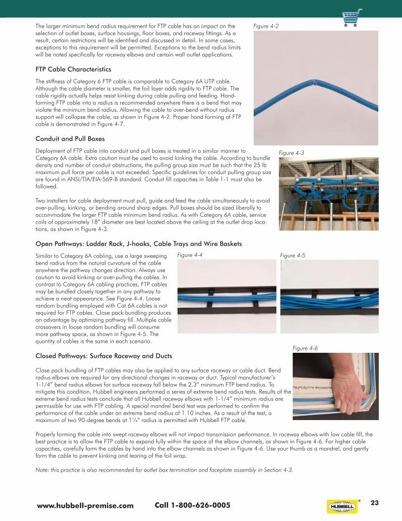
Call 1-800-626-0005www.hubbell-premise.com 23
The larger minimum bend radius requirement for FTP cable has an impact on the selection of outlet boxes, surface housings, floor boxes, and raceway fittings. As a result, certain restrictions will be identified and discussed in detail. In some cases, exceptions to this requirement will be permitted. Exceptions to the bend radius limits will be noted specifically for raceway elbows and certain wall outlet applications.
FTP Cable Characteristics
The stiffness of Category 6 FTP cable is comparable to Category 6A UTP cable. Although the cable diameter is smaller, the foil layer adds rigidity to FTP cable. The cable rigidity actually helps resist kinking during cable pulling and feeding. Hand-forming FTP cable into a radius is recommended anywhere there is a bend that may violate the minimum bend radius. Allowing the cable to over-bend without radius support will collapse the cable, as shown in Figure 4-2. Proper hand forming of FTP cable is demonstrated in Figure 4-7.
Conduit and Pull Boxes
Deployment of FTP cable into conduit and pull boxes is treated in a similar manner to Category 6A cable. Extra caution must be used to avoid kinking the cable. According to bundle density and number of conduit obstructions, the pulling group size must be such that the 25 lb maximum pull force per cable is not exceeded. Specific guidelines for conduit pulling group size are found in ANSI/TIA/EIA-569-B standard. Conduit fill capacities in Table 1-1 must also be followed.
Two installers for cable deployment must pull, guide and feed the cable simultaneously to avoid over-pulling, kinking, or bending around sharp edges. Pull boxes should be sized liberally to accommodate the larger FTP cable minimum bend radius. As with Category 6A cable, service coils of approximately 18” diameter are best located above the ceiling at the outlet drop loca-tions, as shown in Figure 4-3.
Open Pathways: Ladder Rack, J-hooks, Cable Trays and Wire Baskets
Similar to Category 6A cabling, use a large sweeping bend radius from the natural curvature of the cable anywhere the pathway changes direction. Always use caution to avoid kinking or over-pulling the cables. In contrast to Category 6A cabling practices, FTP cables may be bundled closely together in any pathway to achieve a neat appearance. See Figure 4-4. Loose random bundling employed with Cat 6A cables is not required for FTP cables. Close pack bundling produces an advantage by optimizing pathway fill. Multiple cable crossovers in loose random bundling will consume more pathway space, as shown in Figure 4-5. The quantity of cables is the same in each scenario.
Closed Pathways: Surface Raceway and Ducts
Close pack bundling of FTP cables may also be applied to any surface raceway or cable duct. Bend radius elbows are required for any directional changes in raceway or duct. Typical manufacturer’s 1-1/4” bend radius elbows for surface raceway fall below the 2.3” minimum FTP bend radius. To mitigate this condition, Hubbell engineers performed a series of extreme bend radius tests. Results of the extreme bend radius tests conclude that all Hubbell raceway elbows with 1-1/4” minimum radius are permissible for use with FTP cabling. A special mandrel bend test was performed to confirm the performance of the cable under an extreme bend radius of 1.10 inches. As a result of the test, a maximum of two 90-degree bends at 1¼” radius is permitted with Hubbell FTP cable. Properly forming the cable into swept raceway elbows will not impact transmission performance. In raceway elbows with low cable fill, the best practice is to allow the FTP cable to expand fully within the space of the elbow channels, as shown in Figure 4-6. For higher cable capacities, carefully form the cables by hand into the elbow channels as shown in Figure 4-6. Use your thumb as a mandrel, and gently form the cable to prevent kinking and tearing of the foil wrap.
Note: this practice is also recommended for outlet box termination and faceplate assembly in Section 4-3.
Figure 4-2
Figure 4-5Figure 4-4
Figure 4-3
Figure 4-6

Hubbell Premise Wiring • 14 Lord’s Hill Road • Stonington, CT 06378 • Tel: (860) 535-8326 • Fax: (860) 535-832824
Section 4-2: Data Center, Equipment Room, and Telecommunications Room
Rack and Cabinet Applications
Similar to Category 6A cabling, FTP cables are rigid enough to be self-supporting from the vertical channel supports to the panel terminations. However, with the additional weight of the cables, using rear cable management support is recommended. Cables flowing into the rack and panel locations should utilize a large sweeping bend radius of approximately 6” or greater, as shown in Figure 4-7.
Patch Panel Termination and Cable Dressing
The Hubbell shielded patch panel utilizes individual jacks mounted into a 1U modular 19” panel, as shown in Figure 4-8. The chassis bonding wire must be fastened to bare metal frame or a master grounding bar nearby. Installed FTP cable channels must have shield continuity, and must be bonded to ground at one end. Note: bonding FTP cable channels on both ends is not recommended due to potential ground loop currents in the shield layer.
With the modular jack panel, the jack and patch panel termination methods are identical. See “Shielded Jack Termination” below. Individual cables from the mounted jacks should flow into the vertical rack channels with a large sweeping radius as shown in Figure 4-8. Note: unlike Category 6A jack terminations, FTP cables entering the shielded jacks are secured with strain relief ties, and are not permitted to form a sharp bend in this area. This condition will significantly impact wall outlet depth requirements as described in Section 4-3 below.
Shielded Jack Termination: Cable Preparation
Strip off approximately 3” of cable jacket using the score and bend technique. Note: 3” of drain wire is recommended for winding around the foil wrap. Caution: do not slice into the foil layer with the scoring tool. Also, do not over-bend the cable at the score area, or the foil wrap will tear open. See Figure 4-9.
Open the foil layer gently to avoid tearing. Cut off the excess foil to approximately ½” and gently fold back over the cable jacket. Note: this exposes the conductive inner side of the foil. See Figure 4-10. Wind the drain wire tightly around the foil as shown in Figure 4-10. Carefully snip open and remove the cellophane layer, then cut the pairs down to 2” length. See Figure 4-10. Fold away the pairs and cut off the pair separator flush to the cable.
Slightly untwist each pair at the bottom, then comb out and straighten the pairs using a small round tool as shown in Figure 4-11. Angle cut the orange pair as shown to aid insertion into the pre-termination module.
RECOMMENDATIONS - Section 4-1
All of the recommendations for UTP cabling listed in Section 1 apply to FTP cabling, except the random loose bundling requirement.
Use the close pack cable bundling method with Velcro ties to maximize pathway utilization.
Use the hand-forming technique illustrated in Figure 4-6 to prevent cable damage from tight bending.
Figure 4-7
Figure 4-8

Call 1-800-626-0005www.hubbell-premise.com 25
RECOMMENDATIONS - Section 4-2
All of the UTP recommendations of Section 2 apply to FTP cabling also, except for allowing the cable to bend in the exposed pairs behind the jack.
The cable strain relief ties used on the FTP jack are intended to prevent tight cable bending in this area. Avoid kinking the cable behind the jacks in the panel or outlet applications.
Use the close pack cable bundling method with Velcro ties in racks, cabinets, and enclosures to maximize pathway utilization.
Use the hand-forming technique illustrated in Figure 4-6 to prevent cable damage from tight bending in racks, cabinets and enclosures.
Follow detailed manufacturer’s instructions and the recommendations above for FTP panel and jack termination.
Bonding to ground should be at the panel only for each installed FTP link.
Figure 4-9 Figure 4-10 Figure 4-11
Insert the wires fully into the pre-ter-mination module as shown in Figure 4-12. Install the rear strain relief tie through the module and tighten firmly around the cable and foil. Use pliers to tighten the cable tie. Note: do not stretch the cable tie while pulling with pliers. Snip off the excess wires flush with the forward edges as shown in Figure 4-12.
Assemble the module onto the jack and press together using parallel jaw pliers as shown in Figure 4-13. Adjust the pliers to the most parallel position. Install the cable-bonding tie through the jack, and tighten firmly around the winding of the drain wire as shown in Figure 4-14. Use pliers to tighten the cable tie. Note: do not stretch the cable tie while pulling with pliers.
Upon termination of the shielded jack at each end of the Horizontal channel, full continuity to ground is established upon insertion of shielded patch cords in the TR and at the workstation.
Grounding and Bonding: FTP Cabling
For FTP systems to function properly, each permanent link must be bonded to ground at one end, preferably at the panel location. As shown in Figure 4-8, the panel chassis serves as a bonding conductor for each installed jack. For best results, the bonding cord supplied with the FTP panel should be fastened to a copper master ground bar on the rack or enclosure. Otherwise, the panel bonding cord should be fastened to bare metal on the rack or enclosure. Any enclosure or rack to which the FTP panel is mounted must also be properly bonded to the local telecommunications grounding bus bar (TGB) as required per ANSI J-STD-607-A. Bonding an FTP permanent link on both ends is not recommended due to potential ground loop current in the cable shield.
Figure 4-12 Figure 4-13 Figure 4-14

Hubbell Premise Wiring • 14 Lord’s Hill Road • Stonington, CT 06378 • Tel: (860) 535-8326 • Fax: (860) 535-832826
Section 4-3: Horizontal Cabling – Work Area Outlets
This section establishes practical guidelines and restrictions for deployment of FTP cabling into various work area outlets. In some cases, mounting of faceplates with flush-mounted FTP jacks may be prohibited due to cable interference. The larger minimum bend radius of FTP cabling is considered in all of the following applications. As with Category 6A cable, service coiling of FTP cable inside an outlet box is prohibited. Cable back-feed is necessary during the mounting of the faceplate. Bending of cable behind any faceplate must be formed carefully by hand to avoid kinking. Do not use excessive force to install faceplates or connector modules.
Standard Outlet Box Eliminators
As shown in Figure 4-15, when using a flush mount faceplate in a box eliminator application, the theoretical minimum depth of the wall is calculated as follows:
Minimum Wall Depth = Depth of jack + FTP min. bend radius
For a 1.0” approximate jack depth, and a 2.3” minimum FTP cable bend radius,
Minimum Wall Depth = 1.0” + 2.3” = 3.3”
For shallow wall spaces less than 3.0” deep, angle faceplates are recommended for FTP cabling. See “Standard Wall Outlets” described below.
Standard 1-Gang Outlets As a result of the depth requirement calculated above, standard 1-gang outlet boxes will not accept faceplates with flush mounted FTP jacks. Regardless of depth, a 1-gang outlet box will only accept an angled faceplate, with a maximum of two ports in the bottom plate position, as shown in Figure 4-16. Service coiling of FTP cable in any outlet box is prohibited. Conduit entry should be through the top center location of the outlet box. To aid assembly of the faceplate, cables should be hand-formed into a swept radius behind the jacks, as shown in Figure 4-15. Avoid kinking the cables during faceplate assembly.
The Style Line® IFP1-series flush-mounting plates, SecureIT™ plates, and iSTATION™ flush modular plates are recommended with box eliminator applications only, where there is sufficient space behind the wall for cable entry.
Standard 2-Gang Outlets The recommended 2-gang outlet box is the 2-1/4” deep version, with 1-1/4” conduit entering the top center. The 2-gang outlet box will not accept faceplates loaded with flush-mount FTP jacks. A 4-port outlet is achieved with a 1-gang angled faceplate and spacer ring as shown in Figure 4-17. Note: the faceplate must be in-stalled carefully to avoid kinking the cables. A 2-gang modular faceplate with angled fittings may also be used to achieve a maximum of 6 ports. See Figure 4-18. Hand-forming the cables into a swept radius behind the jacks is also recommended to aid faceplate assembly and prevent kinking.
Recessed Wall Boxes: Multi-Connect Series
The 2-gang or 4-gang versions will accommodate 12 ports of FTP cabling through the 2” conduit opening. Installing the faceplates with FTP cabling is more difficult than Category 6A UTP cabling. Cables must be pre-formed into a swept bend to prevent kinking during faceplate installation. See Figure 4-19.
Surface Mount Housings: ISM Series
The Hubbell FTP jack, which is larger than the UTP jack, is not compatible with any of the Hubbell ISM series surface mount housings.
MUTOA Outlets: OFPPL Multimedia Outlet Housing
The Hubbell FTP jack has a taller height than the UTP jack, and is therefore not compatible with the openings in the OFPPL multimedia housing.
Figure 4-16
Figure 4-17
Figure 4-18
Figure 4-19
Figure 4-15
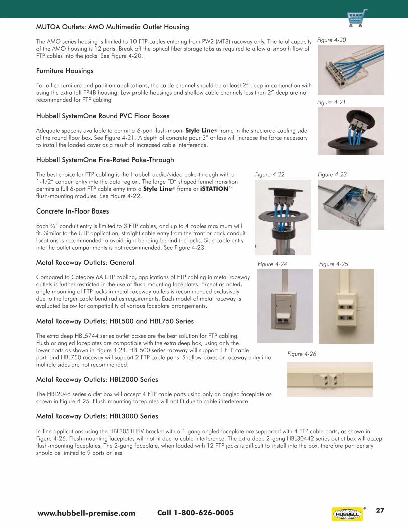
Call 1-800-626-0005www.hubbell-premise.com 27
MUTOA Outlets: AMO Multimedia Outlet Housing
The AMO series housing is limited to 10 FTP cables entering from PW2 (MT8) raceway only. The total capacity of the AMO housing is 12 ports. Break off the optical fiber storage tabs as required to allow a smooth flow of FTP cables into the jacks. See Figure 4-20.
Furniture Housings
For office furniture and partition applications, the cable channel should be at least 2” deep in conjunction with using the extra tall FP4B housing. Low profile housings and shallow cable channels less than 2” deep are not recommended for FTP cabling.
Hubbell SystemOne Round PVC Floor Boxes
Adequate space is available to permit a 6-port flush-mount Style Line® frame in the structured cabling side of the round floor box. See Figure 4-21. A depth of concrete pour 3” or less will increase the force necessary to install the loaded cover as a result of increased cable interference.
Hubbell SystemOne Fire-Rated Poke-Through
The best choice for FTP cabling is the Hubbell audio/video poke-through with a 1-1/2” conduit entry into the data region. The large “D” shaped funnel transition permits a full 6-port FTP cable entry into a Style Line® frame or iSTATION™flush-mounting modules. See Figure 4-22.
Concrete In-Floor Boxes
Each ¾” conduit entry is limited to 3 FTP cables, and up to 4 cables maximum will fit. Similar to the UTP application, straight cable entry from the front or back conduit locations is recommended to avoid tight bending behind the jacks. Side cable entry into the outlet compartments is not recommended. See Figure 4-23.
Metal Raceway Outlets: General
Compared to Category 6A UTP cabling, applications of FTP cabling in metal raceway outlets is further restricted in the use of flush-mounting faceplates. Except as noted, angle mounting of FTP jacks in metal raceway outlets is recommended exclusively due to the larger cable bend radius requirements. Each model of metal raceway is evaluated below for compatibility of various faceplate arrangements.
Metal Raceway Outlets: HBL500 and HBL750 Series
The extra deep HBL5744 series outlet boxes are the best solution for FTP cabling. Flush or angled faceplates are compatible with the extra deep box, using only the lower ports as shown in Figure 4-24. HBL500 series raceway will support 1 FTP cable port, and HBL750 raceway will support 2 FTP cable ports. Shallow boxes or raceway entry into multiple sides are not recommended.
Metal Raceway Outlets: HBL2000 Series
The HBL2048 series outlet box will accept 4 FTP cable ports using only an angled faceplate as shown in Figure 4-25. Flush-mounting faceplates will not fit due to cable interference.
Metal Raceway Outlets: HBL3000 Series
In-line applications using the HBL3051LEIV bracket with a 1-gang angled faceplate are supported with 4 FTP cable ports, as shown in Figure 4-26. Flush-mounting faceplates will not fit due to cable interference. The extra deep 2-gang HBL30442 series outlet box will accept flush-mounting faceplates. The 2-gang faceplate, when loaded with 12 FTP jacks is difficult to install into the box, therefore port density should be limited to 9 ports or less.
Figure 4-26
Figure 4-20
Figure 4-21
Figure 4-22 Figure 4-23
Figure 4-24 Figure 4-25

Hubbell Premise Wiring • 14 Lord’s Hill Road • Stonington, CT 06378 • Tel: (860) 535-8326 • Fax: (860) 535-832828
Metal Raceway Outlets: HBL4750 and HBL6750 Series
The iSTATION™ angled connector modules are compatible Hubbell FTP jacks. Full in-line port density is achieved in the HBL4750 series with four 2-port angle modules as shown in Figure 4-27. Full in-line port density is achieved in the HBL6750 series with six 2-port angle modules as shown in Figure 4-28. Flush- mounting connector modules are not recommended.
Metal Raceway Outlets: HBLALU3800 and HBLALU4800 Series
Hubbell aluminum raceway applications use the same recommendations, using iSTATION™ angled connector modules only. The larger bend radius of FTP cabling does not allow the use of flush-mounting connector modules in the in-line outlet application. See Figure 4-29.
Non-Metallic Raceway Outlets: General
Applications of FTP cabling in non-metallic raceway outlets also have further restrictions. Deep outlet boxes that permit flush mounting are identified. Each model of non-metallic raceway is evaluated below for compatibility with various faceplate and outlet box options.
Non-Metallic Raceway Outlets: PT1 (MT3)
Using PT1 (MT3) raceway, 2 FTP cables maximum are permitted. Using the PT12DBA (MT34DBA) deep outlet box is recommended. Avoid using low profile boxes. Raceway should only enter from the top of the outlet box. The 2-port angle module must be used in the middle or bottom positions only. See Figure 4-30. Note: FTP jacks in the top plate position will interfere with the screw-mounting post. The 2-gang box PT12TGB (MT34TGB) having a 2-cable limit offers no advantage with single raceway entry. Using flush mounting modules, or raceway entry into multiple sides is not recommended.
Non-Metallic Raceway Outlets: PP1 (MT6)
PP1 (MT6) raceway is also limited to 2 FTP cables. Avoid using low profile boxes. The standard PDB12S (MT678SB) box and PDB12D (MT678DB) deep box are suitable using angled modules only in the middle or bottom positions. See Figure 4-31. Note: FTP jacks in the top plate position will interfere with the screw-mounting post. Using flush mounting modules, or raceway entry into multiple sides is not recom-mended. Use PL1 (MT7) raceway for 4-port capacity.
Non-Metallic Raceway Outlets: PL1 (MT7)
PL1 (MT7) raceway has a capacity of 6 FTP cables, and will support a maximum of 4 FTP jacks using the PDB12D (MT678DB) deep box, as shown in Figure 4-32. Note: to reduce cable interference, trim the web off one side of the screw post with a utility knife as shown in Figure 4-33. The 2-gang PT12TGB (MT678CTGB) box is not recommended due to cable interference with the plate mounting posts.
Non-Metallic Raceway Outlets: PW2 (MT8)
PW2 (MT8) raceway has a total capacity of 10 FTP cables, and will support 4 FTP jacks using the PDB12D (MT678DB) deep box. See Figure 4-34. Trimming the web off the screw post per Figure 4-33 also provides more space for the cables to flow out of the outlet. For larger port densities, the AMO housing provides 12-port capacity as shown in Figure 4-20.
Non-Metallic Raceway Outlets: PB3 (MT9)
PB3 (MT9) raceway has a capacity of 11 FTP cables in channels A or C, and 12 FTP cables in the middle channel B. The full capacity in-line device boxes PB3FCIB (MT9FCIB) series are more restrictive using FTP cabling. Note: in the full capacity device box, FTP cables will not route into the outer channels due to interference and multiple bend angles. Only 2 ports from each plate are permitted from the middle channel only, as shown in Figures 4-35 and 4-36.
Figure 4-29 Figure 4-30
Figure 4-32Figure 4-31
Figure 4-33
Figure 4-34 Figure 4-35
Figure 4-36
Figure 4-27 Figure 4-28

Call 1-800-626-0005www.hubbell-premise.com 29
To increase port density, use the PB3FCIB (MT9INDB2) 3-gang flush in-line box. Up to 6 ports are permitted in each channel as shown in Figure 4-37. When routing the cables into the box, carefully form the cables into a radius to prevent kinking during faceplate attachment. Straddle the plate mounting posts on each side with the cables. Also, be sure the wire ties on the jacks are facing inward to avoid interference with the plate opening. The flush PB3IND (MT9IN-DB1) 1-gang in-line box is not recommended due to interference of cables with the plate mounting posts.
Non-Metallic Raceway Outlets: PS3 (MT10) Series
PS3 (MT10) raceway has the largest cable capacity with 21 FTP cables in channel A or C, and 23 FTP cables in channel B. The 3-gang PS3FCIB3G (MT10INDB3) in-line device box will support 4 FTP angle ports per channel as shown in 4-37. Flush-mount plates are not per-mitted. The 1-gang and 2-gang full capacity device boxes PS3FCIB (MT10FCIB) series will support 2 Style Line® flush-mount ports in the middle channel only as shown in Figure 4-38. Note: in the full capacity device box, FTP cables will not route into the outer channels due to interference and multiple bend angles.
RECOMMENDATIONS - Section 4-3
All of the UTP recommendations of Section 3 apply to FTP cabling also, with exceptions as noted below.
Avoid kinking the cable behind the jacks while installing the faceplate.
Use the hand-forming technique as illustrated in Figure 4-6 and 4-15 to pre-bend cables to aid faceplate installation. Note: do not use excessive force to install faceplates with either FTP or UTP jacks.
Adhere to the faceplate recommendations and specific wall outlet restrictions as described above.
In general, due to a larger minimum bend radius requirement, FTP cabling is best deployed to the wall outlet as direct and straight as possible.
Avoid outlet designs that force the cable into tight bends or multiple bend angles.
Employ the proper grounding and bonding practices as described on page 25.
SUMMARY AND CLOSING COMMENTS
The guidelines and recommendations provided in this document serve as a general baseline to designers, installers and end users. Understanding the capacity constraints, restrictions, and special considerations required for Category 6A and FTP cable deployment is extremely important in all phases of a structured cabling project. As described in this document, new installations and cabling retro-fit projects are significantly impacted by the physical constraints of Category 6A and FTP cabling. Continued development by cable manufacturers is focused on reduction of cable diameter and increasing cable flexibility. Future cable designs may alleviate some of the restrictions encountered in this study. Therefore the results obtained in this document serve as a worst-case scenario with current cable designs.
Figure 4-38Figure 4-37

www.hubbell-premise.comWant to learn more? Hubbell puts information at your fingertips.For more complete information on Hubbell Premise Wiring's Connectivity Solutions and Fiber System products and services, our website offers:
Online e-Catalog Press Releases Product Spec Sheets Distributors Case Studies Sales Contacts New Products MISSION CRITICAL® Warranty Cabling Standards Consultants' Corner Application Guides Contractors
or download a copy of HPW's newest brochures:
Access our website at www.hubbell-premise.comor contact our Inside Sales Group for more information at 1-800-626-0005.
10-Gigabit EthernetSolutionsPrepare your infrastructure for what lies ahead.
10GbE SystemsNEXTSPEED® Ascent 10GbE systems have been extensively tested to support existing PoE applications.
10GbE Fiber SystemA cost-effective 10GbE solution for the fiber industry.
B-C6A 8/07
Hubbell Premise WiringHUBBELL INCORPORATED (Delaware)14 Lord’s Hill Road • Stonington, CT 06378-0901 • (860) 535-8326 • 800-626-0005 Fax: (860) 535-8328 • Internet site: http://www.hubbell-premise.com
Hubbell Premise Wiring, Latin America 305-408-4501 Fax: 305-408-8201Hubbell de Mexico, S.A. de C.V. (5255) 9151-9999 Fax: (5255) 9151-9989Hubbell Premise Wiring, Middle East 971-4-393-4192 Fax: 971-4-393-4194Hubbell Premise Wiring, Puerto Rico 787-855-1075 Fax: 787-855-3265Hubbell-Taian Co., Ltd., Taiwan 886-2-2522-1862 Fax: 886-2-2522-1872Hubbell Premise Wiring, Venezuela 58-212-5156482 Fax: 58-212-6627258
Worldwide LocationsHubbell Premise Wiring, Asia Pacific 852-2836-7131 Fax: 852-2836-7132Hubbell Canada Inc. 905-839-1138 Fax: 905-839-9108Hubbell Premise Wiring, Central America 506-309-4158 Fax: 506-260-1616Hubbell Premise Wiring, China 86-21-6374 2660 Fax: 86-21-6374 2799Hubbell Premise Wiring, Europe 44-01283 500500 Fax: 44-01283 500400Hubbell Wiring Systems, India 91-80-4022-4089 Fax: 91-80-4022-4033Hubbell Int’l. Inc., Korea Branch (82 2) 2607 1363 Fax: (82 2) 2603 7386