AudioCodes Fax ATA Connector Service - FaxBack...
41
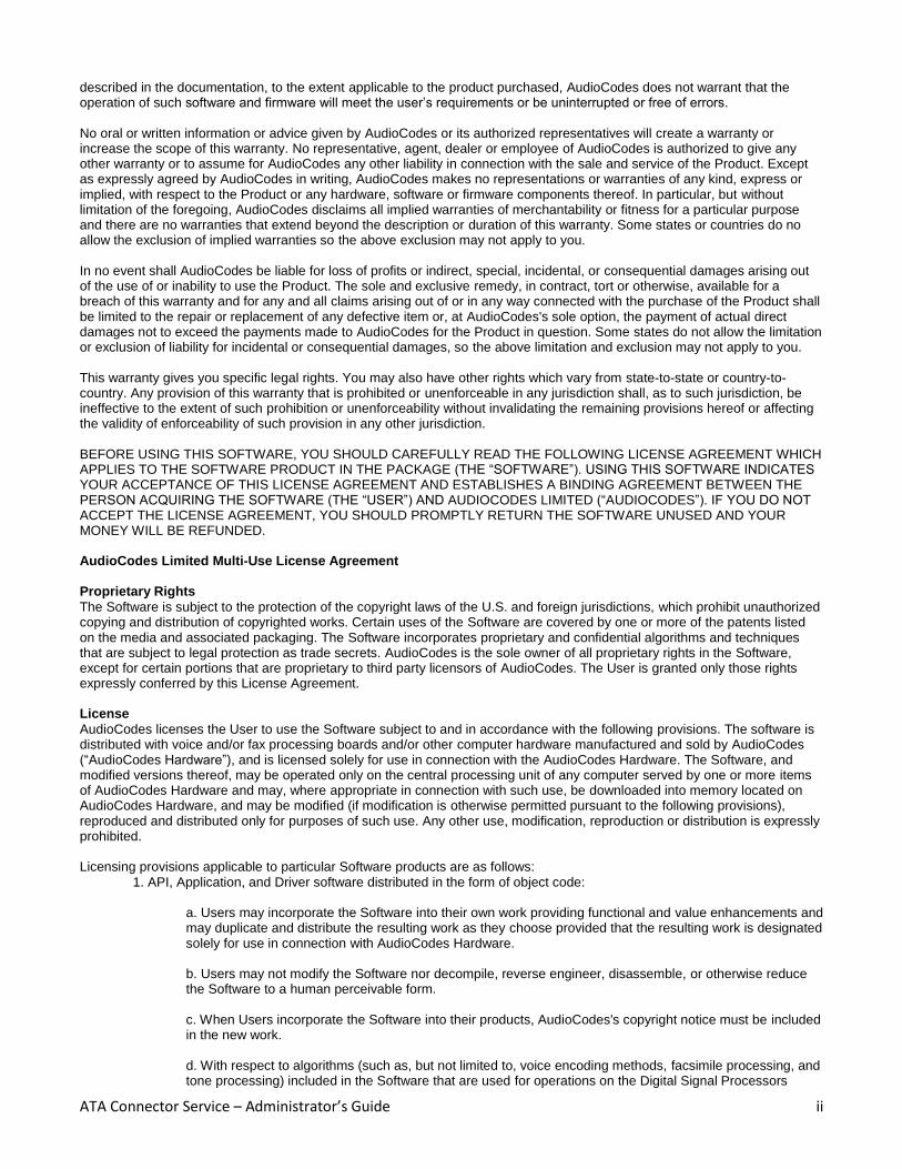
AudioCodes Fax ATA Connector Service Administrators Guide Carrier/Enterprise Edition July 16, 2011 Fax Solution Fax Machine AudioCodes MP-202B HTTPS Enabled Fax ATA PSTN AudioCodes Fax Connector Fax Server SMTP/POP3 (T.37) HTTPS HTTPS HTTPS Abstract This document contains all information required for a system administrator to install and maintain the AudioCodes ATA Connector Service for use with the HTTP(s) fax enabled AudioCodes MP202B HTTPS 2FXS ATA’s. This release of the ATA Connector specifically targets T.37 enabled Fax servers and services used in enterprise environments.
Transcript of AudioCodes Fax ATA Connector Service - FaxBack...

AudioCodes Fax ATA Connector Service
Administrators Guide
Carrier/Enterprise Edition
July 16, 2011
Fax Solution
Fax MachineAudioCodes
MP-202B
HTTPS EnabledFax ATA
PSTNAudioCodes
Fax ConnectorFax ServerSMTP/POP3
(T.37)HTTPS
HTTP
S
HTTPS
Abstract
This document contains all information required for a system administrator to install and maintain the
AudioCodes ATA Connector Service for use with the HTTP(s) fax enabled AudioCodes MP202B HTTPS 2FXS ATA’s.
This release of the ATA Connector specifically targets T.37 enabled Fax servers and services used in enterprise
environments.

ATA Connector Service – Administrator’s Guide i
D I S C L A I M E R
The software described within is copyrighted material and is supplied only under license agreement and is subject to nondisclosure. The software may be copied only in accordance with the terms as described in the software agreement. AudioCodes, LTD makes no warranties with respect to the contents or use of this manual and specifically disclaims any express or implied warranties of merchantability or fitness for any particular purpose. Further, Audio Codes, LTD reserves the right to revise this publication and to make changes to its contents at any time, without obligation to notify any person or entity of such revisions or changes. No part of this or any accompanying documentation may be reproduced., translated into another language, or transmitted in any form or by any means, electronic or mechanical, including photocopying, recording, or scanning, for any purpose without the express written permission of AudioCodes, LTD
T R A D E M A R K S
Microsoft, Windows XP / Vista / Windows 7 / 2003 / 2008 and Exchange are all registered trademarks of Microsoft Corporation.
All other trademarks are owned by their respective owners.
General Notices
Copyright© 2010, AudioCodes Limited.
All rights reserved.
This product may not, in whole or in part, be copied, photocopied, reproduced, translated, or reduced to any electronic medium or machine readable form without prior consent, in writing, from AudioCodes Limited.
AudioCodes Limited reserves the right to make improvements and/or changes in the products and programs described in this Installation Guide at any time without notice. Every attempt has been made to insure that the information contained in this document is accurate and complete. AudioCodes Limited will not be responsible for any inaccuracies or omissions in this or any of its other technical publications. Printed in the United States of America.
Trademarks AudioCodes, AudioCodes Limited, and MediaPack are registered trademarks of AudioCodes Limited.
Microsoft, Windows, the Windows logo, Windows Server 2003, and Windows 2000 are trademarks or registered trademarks of Microsoft Corporation in the United States and/or other countries. Pentium and Intel are registered trademarks of Intel Corporation. Other company or product names mentioned herein may be trademarks or registered trademarks of their respective companies. International Notice Due to differing national regulations and approval requirements, certain AudioCodes products are designed for use only in specific countries, and may not function properly in a country other than the country of designated use. As a user of these products, you are responsible for ensuring that the products are used only in the countries for which they were intended. For information on specific products, contact AudioCodes Limited.
27 World's Fair Drive Somerset, NJ 08873 Tel: +1-732-469-0880 Fax: +1-732-469-2298 www.audiocodes.com AudioCodes Technical Support
For AudioCodes Technical Support, see http://www.audiocodes.com/. Limited Warranty
AudioCodes Limited (“AudioCodes”) warrants the hardware component of the product described in this documentation (the “Product”) to be free from defects in materials and workmanship under normal and proper use for a period of five years from the date of purchase from AudioCodes. AudioCodes also warrants the disk on which software and firmware are recorded to be free from defects in materials and workmanship under normal and proper use for a period of 90 days from the date of purchase from AudioCodes. This warranty does not apply to the software and firmware themselves. This warranty also does not apply to any expendable components, any damage resulting from abuse of the Product, or normal wear and tear. In the event of a warranty claim, the item, if in the opinion of AudioCodes it is proved to be defective, will be repaired or replaced with a functionally equivalent item, at AudioCodes's sole option, upon delivery to AudioCodes of the defective item, together with a dated proof of purchase and specification of the problem. AudioCodes is not responsible for transportation and related charges in connection with shipment of items to AudioCodes for warranty service. AudioCodes reserves the right to charge for inspection at AudioCodes's then prevailing rates of returned items if it is determined that the items were not defective within the terms of the warranty. To obtain warranty service return the Product, contact AudioCodes Technical Support. With respect to software and firmware, it should be understood that these components are complex works which may contain undiscovered defects. Although the software and firmware provided with the Product contain substantially the features
ATA Connector Service – Administrator’s Guide ii
described in the documentation, to the extent applicable to the product purchased, AudioCodes does not warrant that the operation of such software and firmware will meet the user’s requirements or be uninterrupted or free of errors. No oral or written information or advice given by AudioCodes or its authorized representatives will create a warranty or increase the scope of this warranty. No representative, agent, dealer or employee of AudioCodes is authorized to give any other warranty or to assume for AudioCodes any other liability in connection with the sale and service of the Product. Except as expressly agreed by AudioCodes in writing, AudioCodes makes no representations or warranties of any kind, express or implied, with respect to the Product or any hardware, software or firmware components thereof. In particular, but without limitation of the foregoing, AudioCodes disclaims all implied warranties of merchantability or fitness for a particular purpose and there are no warranties that extend beyond the description or duration of this warranty. Some states or countries do no allow the exclusion of implied warranties so the above exclusion may not apply to you. In no event shall AudioCodes be liable for loss of profits or indirect, special, incidental, or consequential damages arising out of the use of or inability to use the Product. The sole and exclusive remedy, in contract, tort or otherwise, available for a breach of this warranty and for any and all claims arising out of or in any way connected with the purchase of the Product shall be limited to the repair or replacement of any defective item or, at AudioCodes's sole option, the payment of actual direct damages not to exceed the payments made to AudioCodes for the Product in question. Some states do not allow the limitation or exclusion of liability for incidental or consequential damages, so the above limitation and exclusion may not apply to you. This warranty gives you specific legal rights. You may also have other rights which vary from state-to-state or country-to-country. Any provision of this warranty that is prohibited or unenforceable in any jurisdiction shall, as to such jurisdiction, be ineffective to the extent of such prohibition or unenforceability without invalidating the remaining provisions hereof or affecting the validity of enforceability of such provision in any other jurisdiction. BEFORE USING THIS SOFTWARE, YOU SHOULD CAREFULLY READ THE FOLLOWING LICENSE AGREEMENT WHICH APPLIES TO THE SOFTWARE PRODUCT IN THE PACKAGE (THE “SOFTWARE”). USING THIS SOFTWARE INDICATES YOUR ACCEPTANCE OF THIS LICENSE AGREEMENT AND ESTABLISHES A BINDING AGREEMENT BETWEEN THE PERSON ACQUIRING THE SOFTWARE (THE “USER”) AND AUDIOCODES LIMITED (“AUDIOCODES”). IF YOU DO NOT ACCEPT THE LICENSE AGREEMENT, YOU SHOULD PROMPTLY RETURN THE SOFTWARE UNUSED AND YOUR MONEY WILL BE REFUNDED. AudioCodes Limited Multi-Use License Agreement
Proprietary Rights
The Software is subject to the protection of the copyright laws of the U.S. and foreign jurisdictions, which prohibit unauthorized copying and distribution of copyrighted works. Certain uses of the Software are covered by one or more of the patents listed on the media and associated packaging. The Software incorporates proprietary and confidential algorithms and techniques that are subject to legal protection as trade secrets. AudioCodes is the sole owner of all proprietary rights in the Software, except for certain portions that are proprietary to third party licensors of AudioCodes. The User is granted only those rights expressly conferred by this License Agreement. License
AudioCodes licenses the User to use the Software subject to and in accordance with the following provisions. The software is distributed with voice and/or fax processing boards and/or other computer hardware manufactured and sold by AudioCodes (“AudioCodes Hardware”), and is licensed solely for use in connection with the AudioCodes Hardware. The Software, and modified versions thereof, may be operated only on the central processing unit of any computer served by one or more items of AudioCodes Hardware and may, where appropriate in connection with such use, be downloaded into memory located on AudioCodes Hardware, and may be modified (if modification is otherwise permitted pursuant to the following provisions), reproduced and distributed only for purposes of such use. Any other use, modification, reproduction or distribution is expressly prohibited. Licensing provisions applicable to particular Software products are as follows:
1. API, Application, and Driver software distributed in the form of object code:
a. Users may incorporate the Software into their own work providing functional and value enhancements and may duplicate and distribute the resulting work as they choose provided that the resulting work is designated solely for use in connection with AudioCodes Hardware. b. Users may not modify the Software nor decompile, reverse engineer, disassemble, or otherwise reduce the Software to a human perceivable form. c. When Users incorporate the Software into their products, AudioCodes's copyright notice must be included in the new work. d. With respect to algorithms (such as, but not limited to, voice encoding methods, facsimile processing, and tone processing) included in the Software that are used for operations on the Digital Signal Processors

ATA Connector Service – Administrator’s Guide iii
(DSPs) of the AudioCodes Hardware, (i) Users may only use or incorporate such algorithms as components of the Software in the form originally supplied by AudioCodes, and may not extract any such algorithms from the Software or use them for any other purpose or permit any end user customer of the Users to have direct access to such algorithms for any purpose; and (ii) Users may only use or incorporate into their products those algorithms that have been licensed under a purchase agreement between the Users and AudioCodes in connection with the specific items of AudioCodes Hardware on which the Software containing such algorithms is to be distributed, and only to the extent of the quantity of AudioCodes Hardware having a total number of ports equal to the number of ports for which the licenses to such Software and the included algorithms have been paid.
2. API, Application, and Driver software distributed in the form of source code:
a. Users may modify the Software and must incorporate it into their own work to provide functional and value enhancements. Users may duplicate and distribute the resulting work in object code form only, provided that the resulting work is designated solely for use in connection with AudioCodes Hardware. Users may not distribute the Software in source form. b. The Software is confidential and proprietary to AudioCodes and Users must protect it in a manner similar to the protection they affords their own confidential and proprietary information. c. When Users incorporate the Software into their products, AudioCodes’s copyright notice must be included in the new work. d. With respect to algorithms (such as, but not limited to, voice encoding methods, facsimile processing, and tone processing) included in the Software that are used for operations on the Digital Signal Processors (DSPs) of the AudioCodes Hardware, (i) Users may only use or incorporate such algorithms as components of the Software in the form originally supplied by AudioCodes, and may not extract any such algorithms from the Software or use them for any other purpose or permit any end user customer of the Users to have direct access to such algorithms for any purpose; and (ii) Users may only use or incorporate into their products those algorithms that have been licensed under a purchase agreement between the Users and AudioCodes in connection with the specific items of AudioCodes Hardware on which the Software containing such algorithms is to be distributed, and only to the extent of the quantity of AudioCodes Hardware having a total number of ports equal to the number of ports for which the licenses to such Software and the included algorithms have been paid.
The reproduction, distribution, and modification rights provided above apply only to AudioCodes Software packaged herewith that bears the label “Multi-Use License Agreement applies.” All other Software distributed by AudioCodes is subject to additional restrictions on reproduction, distribution, and modification. Distribution
Any distribution of the Software (including modified versions) that is authorized hereby shall be made (a) in object form only; (b) only to purchasers of units of AudioCodes Hardware, or of products including AudioCodes Hardware, for which appropriate payment (including payment for the Software that has been distributed) has been made in accordance with the purchase agreement between the Users and AudioCodes and (c) only pursuant to license agreements containing, at a minimum, the following provisions: (i) express acknowledgement of AudioCodes’s and its licensors' proprietary rights in the Software, (ii) a license to use the Software only as installed on the units of AudioCodes Hardware purchased by the licensee, (iii) the express prohibition of any reproduction, modification, or distribution of the Software, (iv) a prohibition on reverse engineering of the Software equivalent to that set forth above, and (v) provisions regarding Termination, Disclaimer of Warranties, and Limitation of Liability, expressed for the benefit of AudioCodes, substantially in the form set forth below. Except as expressly permitted hereby, Users may not distribute the Software, or any copy, by transfer, lease, loan or any other means. Termination
A User's license to use the Software may be terminated by AudioCodes in the event of any failure to comply with the above restrictions or any other terms of this License Agreement. In the event of termination of the license, the User must destroy or return to AudioCodes all copies of the Software in his possession. Limited Warranty
AudioCodes warrants for a period of 90 days following delivery that the media on which the Software is recorded is free from defects in materials and workmanship. AudioCodes does not warrant that operation of the Software will be uninterrupted or error-free, or that it will satisfy the User's requirements. AUDIOCODES DISCLAIMS ALL OTHER WARRANTIES EXPRESSED OR IMPLIED, INCLUDING ANY IMPLIED WARRANTIES OF MERCHANTABILITY, FITNESS FOR A PARTICULAR PURPOSE, OR NON-INFRINGEMENT. Limitation of Liability

ATA Connector Service – Administrator’s Guide iv
AudioCodes's entire liability and the User's exclusive remedy in connection with the Software will be the replacement
of any media not meeting the above limited warranty upon return of the media to AudioCodes. In no event will
AudioCodes be liable for damages, including any lost profits or other incidental or consequential damages, arising
out of or related to the Software and its use, even if AudioCodes has been advised of the possibility of such
damages.
Contents
1 Overview .............................................................................................................................................................1
1.1 Fax Machine Usage .....................................................................................................................................2
1.2 Fax Machine Experience – Similarities and Differences .............................................................................3
1.3 Receiving Faxes and Notifications ..............................................................................................................3
2 ATA Connector System Requirements ...............................................................................................................3
2.1 Supported Fax Solutions .............................................................................................................................4
2.2 Database (SQL) ...........................................................................................................................................5
2.3 Email Systems .............................................................................................................................................5
2.4 Virtualization ..............................................................................................................................................5
2.5 ATAs (MP-202B HTTPS Fax Enabled) ..........................................................................................................5
3 Deployment Models ...........................................................................................................................................5
3.1 Fax Server & Service ...................................................................................................................................5
4 Installation Overview ..........................................................................................................................................6
4.1 ATA Connector Service Installation ............................................................................................................6
4.1.1 Operating system hooks and visibility ................................................................................................7
4.2 Fax Server or Service Configuration ...........................................................................................................8
4.3 Web Management ......................................................................................................................................8
4.4 ATA Usage ...................................................................................................................................................8
5 Configuration ......................................................................................................................................................9
5.1 Single Server (Default Installation) .......................................................................................................... 12
5.2 Advanced Server Configuration ............................................................................................................... 12
5.2.1 External Database Configuration ..................................................................................................... 12
5.2.2 Single Server with HTTP(s) Secure Proxy ......................................................................................... 14
5.2.3 Dual Server ...................................................................................................................................... 15
5.2.4 Multi-Server High Availability .......................................................................................................... 16
5.3 Service Security ....................................................................................................................................... 17
5.4 HTTP(s) Secure Proxy Configuration ........................................................................................................ 17
5.4.1 Configuring Internet Information Services 6 (IIS6) with the HTTP(s) Secure Proxy ........................ 18
5.4.2 Configuring Internet Information Services 7 (IIS7) with the HTTP(s) Secure Proxy ........................ 22
5.5 Call-Ahead Mode ..................................................................................................................................... 24
5.6 ATA: MP-202B Configuration................................................................................................................... 24
5.6.1 Basic ATA Setup ............................................................................................................................... 27
ATA Connector Service – Administrator’s Guide vi
5.6.2 Finding the ATAs IP Address ............................................................................................................ 27
5.6.3 Entering the PIN on the ATA ............................................................................................................ 27
5.7 Entering HTTP(s) Connection Information .............................................................................................. 28
5.8 Manual ATA Configuration ...................................................................................................................... 28
5.8.1 Automatic ATA Provisioning ............................................................................................................ 29
5.9 Web Administration ................................................................................................................................ 29
6 Maintenance Tasks .......................................................................................................................................... 31
6.1 Starting & Stopping ATA Connector ........................................................................................................ 31
7 Diagnostic’s and Trouble Shooting .................................................................................................................. 32
7.1 Windows Event Viewer ........................................................................................................................... 32
7.2 Log Viewer ............................................................................................................................................... 33
7.3 ATA Audio Error Messages ...................................................................................................................... 33
7.4 IPFS Manager ........................................................................................................................................... 33
7.5 Contacting Support .................................................................................................................................. 34
ATA Connector Service – Administrator’s Guide Page 1 of 34
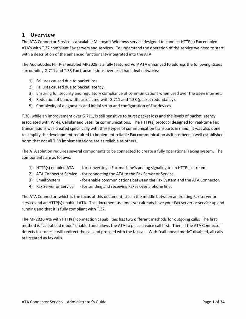
1 Overview The ATA Connector Service is a scalable Microsoft Windows service designed to connect HTTP(s) Fax enabled
ATA’s with T.37 compliant Fax servers and services. To understand the operation of the service we need to start
with a description of the enhanced functionality integrated into the ATA.
The AudioCodes HTTP(s) enabled MP202B is a fully featured VoIP ATA enhanced to address the following issues
surrounding G.711 and T.38 Fax transmissions over less than ideal networks:
1) Failures caused due to packet loss.
2) Failures caused due to packet latency.
3) Ensuring full security and regulatory compliance of communications when used over the open internet.
4) Reduction of bandwidth associated with G.711 and T.38 (packet redundancy).
5) Complexity of diagnostics and initial setup and configuration of Fax devices.
T.38, while an improvement over G.711, is still sensitive to burst packet loss and the levels of packet latency
associated with Wi-Fi, Cellular and Satellite communications. The HTTP(s) protocol designed for real-time Fax
transmissions was created specifically with these types of communication transports in mind. It was also done
to simplify the development required to implement reliable Fax communication as it has been a well established
norm that not all T.38 implementations are as reliable as others.
The ATA solution requires several components to be connected to create a fully operational Faxing system. The
components are as follows:
1) HTTP(s) enabled ATA - for converting a Fax machine’s analog signaling to an HTTP(s) stream.
2) ATA Connector Service - for connecting the ATA to the Fax Server or Service.
3) Email System - for enable communications between the Fax System and the ATA Connector.
4) Fax Server or Service - for sending and receiving Faxes over a phone line.
The ATA Connector, which is the focus of this document, sits in the middle between an existing Fax server or
service and an HTTP(s) enabled ATA. This document assumes you already have your Fax server or service up and
running and that it is fully compliant with T.37.
The MP202B Ata with HTTP(s) connection capabilities has two different methods for outgoing calls. The first
method is “call-ahead mode” enabled and allows the ATA to place a voice call first. Then, if the ATA Connector
detects fax tones it will redirect the call and proceed with the fax call. With “call-ahead mode” disabled, all calls
are treated as fax calls.
ATA Connector Service – Administrator’s Guide Page 2 of 34
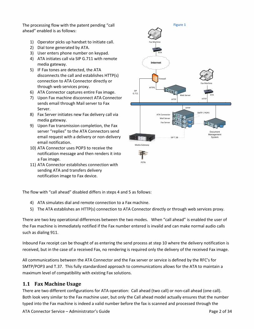
The processing flow with the patent pending “call ahead” enabled is as follows:
1) Operator picks up handset to initiate call. 2) Dial tone generated by ATA. 3) User enters phone number on keypad. 4) ATA initiates call via SIP G.711 with remote
media gateway. 5) IF Fax tones are detected, the ATA
disconnects the call and establishes HTTP(s) connection to ATA Connector directly or through web services proxy.
6) ATA Connector captures entire Fax image. 7) Upon Fax machine disconnect ATA Connector
sends email through Mail server to Fax Server.
8) Fax Server initiates new Fax delivery call via media gateway.
9) Upon Fax transmission completion, the Fax server “replies” to the ATA Connectors send email request with a delivery or non-delivery email notification.
10) ATA Connector uses POP3 to receive the notification message and then renders it into a Fax image.
11) ATA Connector establishes connection with sending ATA and transfers delivery notification image to Fax device.
Figure 1
PSTN
Media Gateway
Fax Machine
ATA
Internet
Firewall
Mail Server
ATA Connector
Fax Server
SMTP / POP3
Document
Management
System
Web Server
SIP T.38
HTTPS
HTTP
Fax Machine
ATA
HTTP
SIPG.711
HTTP
The flow with “call ahead” disabled differs in steps 4 and 5 as follows:
4) ATA simulates dial and remote connection to a Fax machine.
5) The ATA establishes an HTTP(s) connection to ATA Connector directly or through web services proxy.
There are two key operational differences between the two modes. When “call ahead” is enabled the user of
the Fax machine is immediately notified if the Fax number entered is invalid and can make normal audio calls
such as dialing 911.
Inbound Fax receipt can be thought of as entering the send process at step 10 where the delivery notification is
received, but in the case of a received Fax, no rendering is required only the delivery of the received Fax image.
All communications between the ATA Connector and the Fax server or service is defined by the RFC’s for
SMTP/POP3 and T.37. This fully standardized approach to communications allows for the ATA to maintain a
maximum level of compatibility with existing Fax solutions.
1.1 Fax Machine Usage There are two different configurations for ATA operation: Call ahead (two call) or non-call ahead (one call).
Both look very similar to the Fax machine user, but only the Call ahead model actually ensures that the number
typed into the Fax machine is indeed a valid number before the fax is scanned and processed through the
ATA Connector Service – Administrator’s Guide Page 3 of 34
system. When configured for “Call ahead” mode the ATA will dial the phone number entered similarly to any
other VoIP call. If Fax tones are detected, the “voice” call will be terminated and the fax will be scanned and
sent to connector service for sending the fax via the defined fax server or service. This mode ensures that
emergency services are still operational from the Fax machine and that a user will not type in an invalid fax
number and walk away assuming they are good to go.
1.2 Fax Machine Experience – Similarities and Differences The send fax experience is very similar from a dial and send perspective, the user walks up to the fax machine
puts the paper in the device, lifts the handset, dials a number, waits for fax tones and presses send. If the ATA is
configured for “Call ahead” mode, this operational segment is identical to normal fax machine operation. If the
ATA is not configured for “Call ahead” mode then the user will not have any immediate feedback for whether
the fax number entered was valid or not until the delivery notification comes in.
Once the fax image has been scanned and delivered to the Fax connector, the operation of the fax machine is
altered from what is conventional. The user does not know at the time the call hangs up if the fax will be
successfully delivered, all the user knows is that the fax was successfully delivered to the ATA Connector.
After submission of the fax to the Connector, the Connector will then submit the fax to the defined fax server or
service for actual fax transmission over a phone line. Depending whether or not the submitted fax is successful
or not, a delivery or non-delivery notification will be sent back to the fax machine. Because the ATA Connector
will be responsible for delivery and non-delivery notifications, the built in notification of the fax machine should
be disabled.
1.3 Receiving Faxes and Notifications The ATA Connector continuously polls a designated POP3 account for each connected ATA port. If a fax is
received in the mailbox, the fax image will be delivered and printed to the Fax machine identically to if it had
been received in real-time. The key differences between a “traditional” fax delivery and fax delivery through a
ATA Connector is that the CSID will be the ATA Connector default and the transfer time will be shortly delayed
from the original receipt timestamp.
If a delivery notification is received into the POP3 account is will be treated similarly to a received fax with one
significant distinction. In the case of the delivery notification, the email message body is rendered and delivered
to the fax machine not the attachment. It is presumed that any attachments included with a delivery
notification are the original fax which was sent and thus is not rendered to the fax machine again. This model of
operation puts the format of the delivery notification completely in the hands of the fax server or service being
used, including all transaction details.
2 ATA Connector System Requirements The ATA connector was designed with the assumption that it would often be installed in a shared resource
environment together with a Fax Server. When viewing the diagrams throughout this documentation please
note that there are no restrictions preventing all of the components from all running on the same machine.

ATA Connector Service – Administrator’s Guide Page 4 of 34
System Requirements:
Operating System
o Windows Server 2008 and 2008 R2 (all editions, releases and service packs)
o Windows Server 2003 (all editions, releases and service packs)
o Windows 7 (all editions, releases and service packs)
o Windows XP Professional SP2 and SP3
CPU 2.0 GHz or faster Intel or AMD processor
RAM 1 GB RAM (200M Available)
100M Hard drive space
Microsoft .NET 3.5
Windows PowerShell 2.0
2.1 Supported Fax Solutions The ATA Connector was designed to communicate generically via SMTP / POP3 with T.37 enabled fax servers
and services. The T.37 standard is very basic in its requirements. Fax servers and services must support faxing
via SMTP {phone number}@{email domain} and must be able to support TIF Class F Fax image attachments. All
servers and services compliant to these specifications should be able to work reliably with the connector.
For full featured operation of the ATA Connector, the connector must be able to:
1) Detect if a received email is a received fax or a delivery notification.
2) Detect if a received email is a success or failure notification.
3) Determine the called phone number associated with the notification.
The ATA Connector uses an open source PowerShell script to parse incoming emails, such that IT personnel will
be able to customize the processing for any non-natively supported servers or services. The currently certified
list is as follows:
Certified Fax Servers:
NET SatisFAXtion – FaxBack RightFax - Open Text XMedius - Sagem HylaFax - Linux Open Source Faxcore
Certified Fax Services:
FaxSIPit EasyLink eFax - j2 myFax - Protus Fax2Mail - Premiere Global
ATA Connector Service – Administrator’s Guide Page 5 of 34
2.2 Database (SQL) The ATA Connector is designed for use with Microsoft SQL CE and the full featured SQL server database engines.
A full featured SQL server is required for Enterprise full failover configuration but adds little value for non-
failover configurations due to the relatively small amount of data managed in the databases.
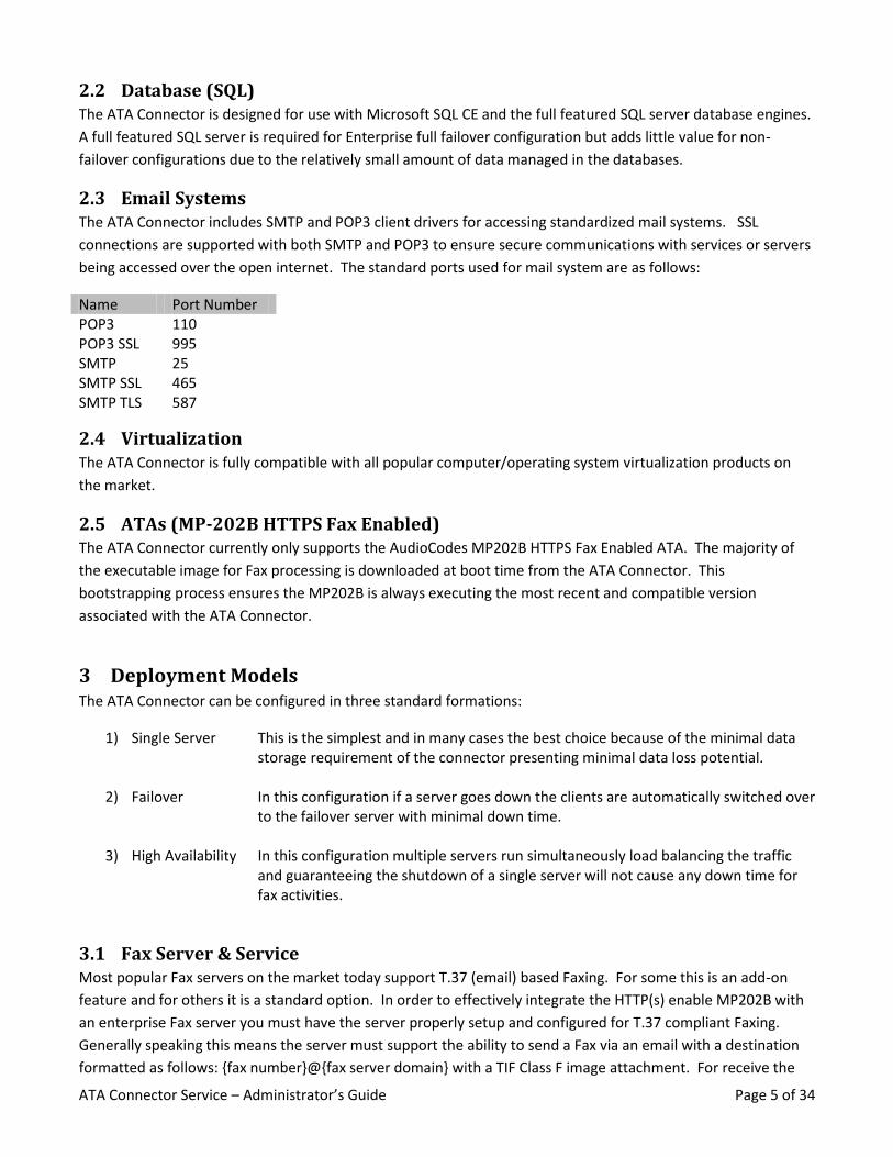
2.3 Email Systems The ATA Connector includes SMTP and POP3 client drivers for accessing standardized mail systems. SSL
connections are supported with both SMTP and POP3 to ensure secure communications with services or servers
being accessed over the open internet. The standard ports used for mail system are as follows:
Name Port Number POP3 110 POP3 SSL 995 SMTP 25 SMTP SSL SMTP TLS
465 587
2.4 Virtualization The ATA Connector is fully compatible with all popular computer/operating system virtualization products on
the market.
2.5 ATAs (MP-202B HTTPS Fax Enabled) The ATA Connector currently only supports the AudioCodes MP202B HTTPS Fax Enabled ATA. The majority of
the executable image for Fax processing is downloaded at boot time from the ATA Connector. This
bootstrapping process ensures the MP202B is always executing the most recent and compatible version
associated with the ATA Connector.
3 Deployment Models The ATA Connector can be configured in three standard formations:
1) Single Server This is the simplest and in many cases the best choice because of the minimal data storage requirement of the connector presenting minimal data loss potential.
2) Failover In this configuration if a server goes down the clients are automatically switched over to the failover server with minimal down time.
3) High Availability
In this configuration multiple servers run simultaneously load balancing the traffic and guaranteeing the shutdown of a single server will not cause any down time for fax activities.
3.1 Fax Server & Service Most popular Fax servers on the market today support T.37 (email) based Faxing. For some this is an add-on
feature and for others it is a standard option. In order to effectively integrate the HTTP(s) enable MP202B with
an enterprise Fax server you must have the server properly setup and configured for T.37 compliant Faxing.
Generally speaking this means the server must support the ability to send a Fax via an email with a destination
formatted as follows: {fax number}@{fax server domain} with a TIF Class F image attachment. For receive the
ATA Connector Service – Administrator’s Guide Page 6 of 34
Fax server must deliver TIF Class F image attachments to an email mailbox which can have mail retrieved via the
POP3 mail protocol.
If a Fax server does not support standardized T.37 Faxing a custom interfacing script can be created and may be
available. Please contact the Fax server vendor or the AudioCodes website for the most recent list of support
products.
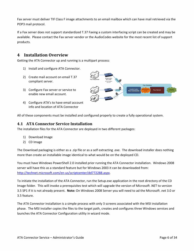
4 Installation Overview Getting the ATA Connector up and running is a multipart process:
1) Install and configure ATA Connector.
2) Create mail account on email T.37 compliant server.
3) Configure Fax server or service to enable new email account.
4) Configure ATA’s to have email account info and location of ATA Connector
Fax Solution
Fax MachineAudioCodes
MP-202B
HTTPS EnabledFax ATA
PSTNAudioCodes
Fax ConnectorFax ServerSMTP/POP3
(T.37)HTTPS
HTTP
S
HTTPS
All of these components must be installed and configured properly to create a fully operational system.
4.1 ATA Connector Service Installation The installation files for the ATA Connector are deployed in two different packages:
1) Download Image
2) CD Image
The Download packaging is either as a .zip file or as a self extracting .exe. The download installer does nothing
more than create an installable image identical to what would be on the deployed CD.
You must have Windows PowerShell 2.0 installed prior running the ATA Connector installation. Windows 2008
server will have this as a standard feature but for Windows 2003 it can be downloaded from:
http://technet.microsoft.com/en-us/scriptcenter/dd772288.aspx.
To initiate the installation of the ATA Connector, run the Setup.exe application in the root directory of the CD
Image folder. This will invoke a prerequisites test which will upgrade the version of Microsoft .NET to version
3.5 SP1 if it is not already present. Note: On Windows 2008 Server you will need to ad the Microsoft .net 3.0 or
3.5 feature.
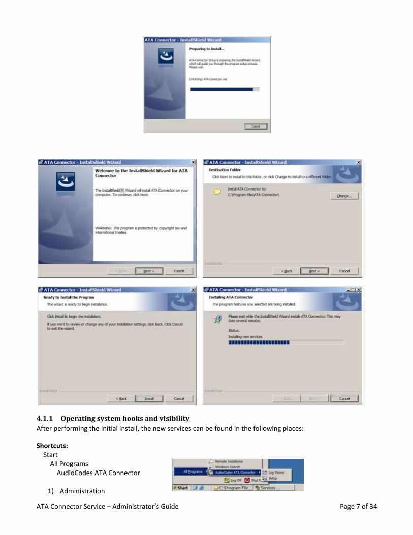
The ATA Connector installation is a simple process with only 3 screens associated with the MSI installation
phase. The MSI installer copies the files to the target path, creates and configures three Windows services and
launches the ATA Connector Configuration utility in wizard mode.
ATA Connector Service – Administrator’s Guide Page 7 of 34
4.1.1 Operating system hooks and visibility
After performing the initial install, the new services can be found in the following places:
Shortcuts: Start All Programs AudioCodes ATA Connector
1) Administration
ATA Connector Service – Administrator’s Guide Page 8 of 34
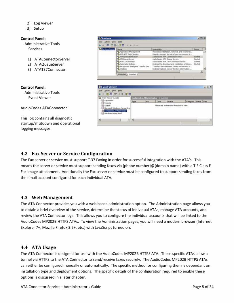
2) Log Viewer 3) Setup
Control Panel: Administrative Tools Services
1) ATAConnectorServer 2) ATAQueueServer 3) ATAT37Connector
Control Panel: Administrative Tools Event Viewer AudioCodes.ATAConnector This log contains all diagnostic startup/shutdown and operational logging messages.
4.2 Fax Server or Service Configuration The Fax server or service must support T.37 Faxing in order for successful integration with the ATA’s. This
means the server or service must support sending faxes via {phone number}@{domain name} with a TIF Class F
Fax image attachment. Additionally the Fax server or service must be configured to support sending faxes from
the email account configured for each individual ATA.
4.3 Web Management The ATA Connector provides you with a web based administration option. The Administration page allows you
to obtain a brief overview of the service, determine the status of individual ATAs, manage ATA accounts, and
review the ATA Connector logs. This allows you to configure the individual accounts that will be linked to the
AudioCodes MP202B HTTPS ATAs. To view the Administration pages, you will need a modern browser (Internet
Explorer 7+, Mozilla Firefox 3.5+, etc.) with JavaScript turned on.
4.4 ATA Usage The ATA Connector is designed for use with the AudioCodes MP202B HTTPS ATA. These specific ATAs allow a
tunnel via HTTPS to the ATA Connector to send/receive faxes securely. The AudioCodes MP202B HTTPS ATAs
can either be configured manually or automatically. The specific method for configuring them is dependant on
installation type and deployment options. The specific details of the configuration required to enable these
options is discussed in a later chapter.
ATA Connector Service – Administrator’s Guide Page 9 of 34
5 Configuration
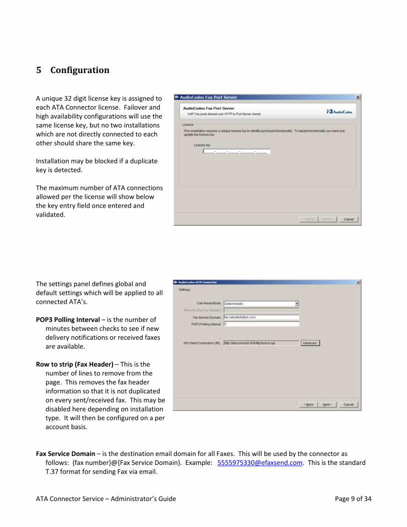
A unique 32 digit license key is assigned to each ATA Connector license. Failover and high availability configurations will use the same license key, but no two installations which are not directly connected to each other should share the same key. Installation may be blocked if a duplicate key is detected. The maximum number of ATA connections allowed per the license will show below the key entry field once entered and validated.
The settings panel defines global and default settings which will be applied to all connected ATA’s. POP3 Polling Interval – is the number of
minutes between checks to see if new delivery notifications or received faxes are available.
Row to strip (Fax Header) – This is the
number of lines to remove from the page. This removes the fax header information so that it is not duplicated on every sent/received fax. This may be disabled here depending on installation type. It will then be configured on a per account basis.
Fax Service Domain – is the destination email domain for all Faxes. This will be used by the connector as follows: {fax number}@{Fax Service Domain}. Example: [email protected]. This is the standard T.37 format for sending Fax via email.
ATA Connector Service – Administrator’s Guide Page 10 of 34
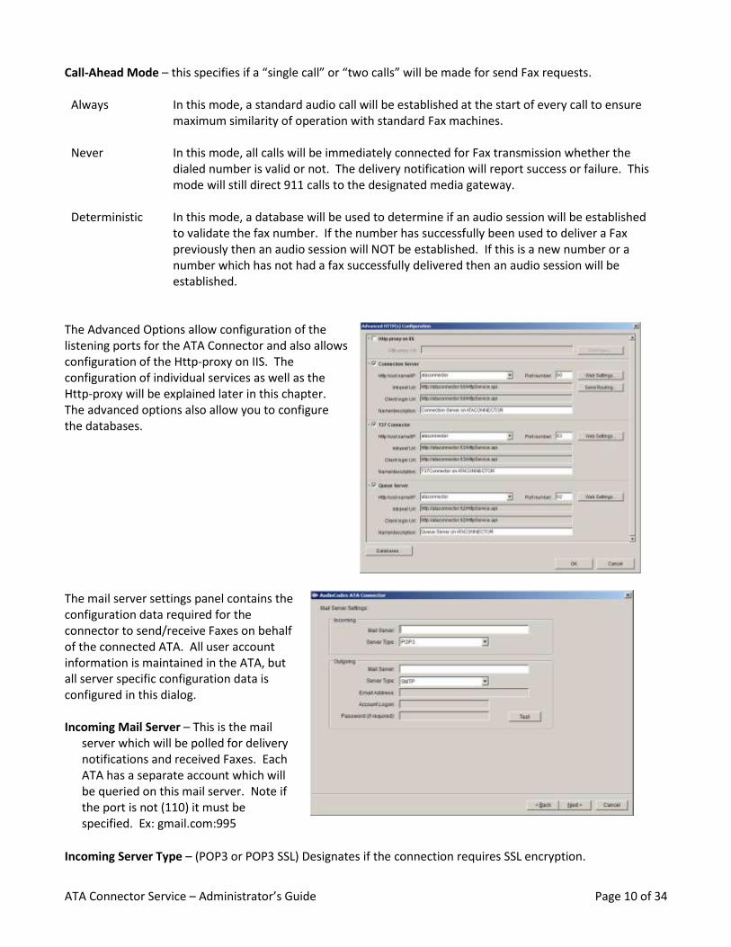
Call-Ahead Mode – this specifies if a “single call” or “two calls” will be made for send Fax requests.
Always In this mode, a standard audio call will be established at the start of every call to ensure maximum similarity of operation with standard Fax machines.
Never In this mode, all calls will be immediately connected for Fax transmission whether the dialed number is valid or not. The delivery notification will report success or failure. This mode will still direct 911 calls to the designated media gateway.
Deterministic
In this mode, a database will be used to determine if an audio session will be established to validate the fax number. If the number has successfully been used to deliver a Fax previously then an audio session will NOT be established. If this is a new number or a number which has not had a fax successfully delivered then an audio session will be established.
The Advanced Options allow configuration of the listening ports for the ATA Connector and also allows configuration of the Http-proxy on IIS. The configuration of individual services as well as the Http-proxy will be explained later in this chapter. The advanced options also allow you to configure the databases.
The mail server settings panel contains the configuration data required for the connector to send/receive Faxes on behalf of the connected ATA. All user account information is maintained in the ATA, but all server specific configuration data is configured in this dialog. Incoming Mail Server – This is the mail
server which will be polled for delivery notifications and received Faxes. Each ATA has a separate account which will be queried on this mail server. Note if the port is not (110) it must be specified. Ex: gmail.com:995
Incoming Server Type – (POP3 or POP3 SSL) Designates if the connection requires SSL encryption.
ATA Connector Service – Administrator’s Guide Page 11 of 34
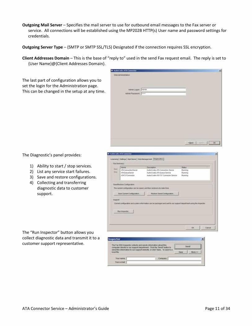
Outgoing Mail Server – Specifies the mail server to use for outbound email messages to the Fax server or service. All connections will be established using the MP202B HTTP(s) User name and password settings for credentials.
Outgoing Server Type – (SMTP or SMTP SSL/TLS) Designated if the connection requires SSL encryption. Client Addresses Domain – This is the base of “reply to” used in the send Fax request email. The reply is set to
{User Name}@{Client Addresses Domain}. The last part of configuration allows you to set the login for the Administration page. This can be changed in the setup at any time.
The Diagnostic’s panel provides:
1) Ability to start / stop services. 2) List any service start failures. 3) Save and restore configurations. 4) Collecting and transferring
diagnostic data to customer support.
The “Run Inspector” button allows you collect diagnostic data and transmit it to a customer support representative.

ATA Connector Service – Administrator’s Guide Page 12 of 34
5.1 Single Server (Default Installation) The simplest configuration model is what you get if the installation is clicked straight through without making any advanced configuration changes. In this model no user account data is managed by the ATA Connector, only cached and all other data stored in the SQL CE database is dynamically generated or a part of the default installation file set. This allows the simplest configuration to be completely reliable for enterprise environments with low numbers of Fax machines; 10 or less.
PSTN
Media Gateway
SIP T.38
Fax Machine
ATA
Mail Server
ATA Connector
Fax Server
SMTP / POP3
5.2 Advanced Server Configuration Selecting the “Advanced…” button on the Settings
tab of the setup will bring you into the advanced
configuration dialog which allows for:
1) Proxy Installation
2) Separation of Services to different
machines.
3) Customized ports and domain settings.
4) Selection of Database and database
connectivity options.
5.2.1 External Database Configuration
Clicking on the Databases allows you to get the
properties of any table and select what type of
database you connect to and the credentials used
to connect. This will allow you to use an external
SQL server. This is where you will configure the
external SQL server for dual and multiple server
configurations.
ATA Connector Service – Administrator’s Guide Page 13 of 34
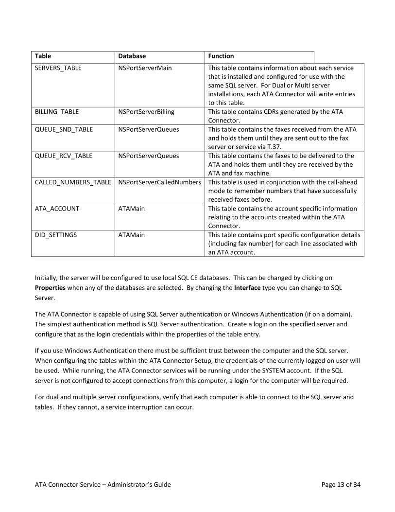
Table Database Function
SERVERS_TABLE NSPortServerMain This table contains information about each service that is installed and configured for use with the same SQL server. For Dual or Multi server installations, each ATA Connector will write entries to this table.
BILLING_TABLE NSPortServerBilling This table contains CDRs generated by the ATA Connector.
QUEUE_SND_TABLE NSPortServerQueues This table contains the faxes received from the ATA and holds them until they are sent out to the fax server or service via T.37.
QUEUE_RCV_TABLE NSPortServerQueues This table contains the faxes to be delivered to the ATA and holds them until they are received by the ATA and fax machine.
CALLED_NUMBERS_TABLE NSPortServerCalledNumbers This table is used in conjunction with the call-ahead mode to remember numbers that have successfully received faxes before.
ATA_ACCOUNT ATAMain This table contains the account specific information relating to the accounts created within the ATA Connector.
DID_SETTINGS ATAMain This table contains port specific configuration details (including fax number) for each line associated with an ATA account.
Initially, the server will be configured to use local SQL CE databases. This can be changed by clicking on
Properties when any of the databases are selected. By changing the Interface type you can change to SQL
Server.
The ATA Connector is capable of using SQL Server authentication or Windows Authentication (if on a domain).
The simplest authentication method is SQL Server authentication. Create a login on the specified server and
configure that as the login credentials within the properties of the table entry.
If you use Windows Authentication there must be sufficient trust between the computer and the SQL server.
When configuring the tables within the ATA Connector Setup, the credentials of the currently logged on user will
be used. While running, the ATA Connector services will be running under the SYSTEM account. If the SQL
server is not configured to accept connections from this computer, a login for the computer will be required.
For dual and multiple server configurations, verify that each computer is able to connect to the SQL server and
tables. If they cannot, a service interruption can occur.

ATA Connector Service – Administrator’s Guide Page 14 of 34
5.2.2 Single Server with HTTP(s) Secure Proxy
Refer to section 5.3 on installation and configuration of the HTTP(s) Secure Proxy. Either during or after you have installed the ATA Connector, you can go into Settings Advanced options and check the Http-proxy on IIS box. If it does not bring up the following automatically, click the configure button.
If you have changed the IIS host name/IP please update it within this screen. The Http Proxy Routing table lists the available targets. These are used to route to the individual services. If the IIS hosting the Http Proxy is on another server, select the dropdown and choose On another computer. Give the full URL for the proxy and click Get Routing Table From Host. This will fill out the Http Proxy Routing Table below. Click Ok. All of the Client login Url entries will have changed to be a target that exists on the proxy. For example, https://ataconnector/nsps/nsps.aspx?target=conserv is the new target for the Connection Server. Click Ok on the Advanced HTTP(s) Configuration when done. Please write down the new ATA Client Connection URL as you will need this for configuring the ATA.
PSTN
Media Gateway
Fax Machine
ATA
Internet
Firewall
Mail Server
ATA Connector
Fax Server
SMTP / POP3
Web Server
SIP T.38
HTTPS
HTTP
Fax Machine
ATA
HTTP
SIPG.711
HTTP
ATA Connector Service – Administrator’s Guide Page 15 of 34
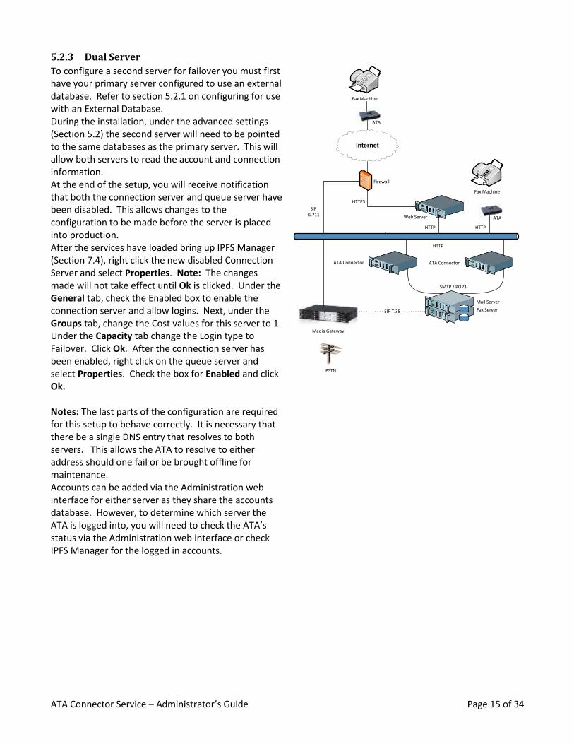
5.2.3 Dual Server
To configure a second server for failover you must first have your primary server configured to use an external database. Refer to section 5.2.1 on configuring for use with an External Database. During the installation, under the advanced settings (Section 5.2) the second server will need to be pointed to the same databases as the primary server. This will allow both servers to read the account and connection information. At the end of the setup, you will receive notification that both the connection server and queue server have been disabled. This allows changes to the configuration to be made before the server is placed into production. After the services have loaded bring up IPFS Manager (Section 7.4), right click the new disabled Connection Server and select Properties. Note: The changes made will not take effect until Ok is clicked. Under the General tab, check the Enabled box to enable the connection server and allow logins. Next, under the Groups tab, change the Cost values for this server to 1. Under the Capacity tab change the Login type to Failover. Click Ok. After the connection server has been enabled, right click on the queue server and select Properties. Check the box for Enabled and click Ok. Notes: The last parts of the configuration are required for this setup to behave correctly. It is necessary that there be a single DNS entry that resolves to both servers. This allows the ATA to resolve to either address should one fail or be brought offline for maintenance. Accounts can be added via the Administration web interface for either server as they share the accounts database. However, to determine which server the ATA is logged into, you will need to check the ATA’s status via the Administration web interface or check IPFS Manager for the logged in accounts.
PSTN
Media Gateway
Fax Machine
ATA
Internet
Firewall
ATA Connector
Web Server
SIP T.38
HTTPS
HTTP
Fax Machine
ATA
HTTP
SIPG.711
HTTP
Mail Server
ATA Connector
Fax Server
SMTP / POP3
ATA Connector Service – Administrator’s Guide Page 16 of 34
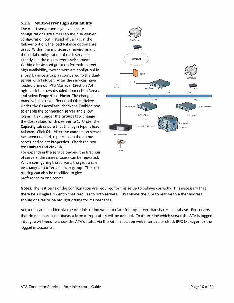
5.2.4 Multi-Server High Availability
The multi-server and high availability configurations are similar to the dual-server configuration but instead of using just the failover option, the load balance options are used. Within the multi-server environment the initial configuration of each server is exactly like the dual-server environment. Within a basic configuration for multi-server high availability, two servers are configured in a load balance group as compared to the dual-server with failover. After the services have loaded bring up IPFS Manager (Section 7.4), right click the new disabled Connection Server and select Properties. Note: The changes made will not take effect until Ok is clicked. Under the General tab, check the Enabled box to enable the connection server and allow logins. Next, under the Groups tab, change the Cost values for this server to 1. Under the Capacity tab ensure that the login type is load-balance. Click Ok. After the connection server has been enabled, right click on the queue server and select Properties. Check the box for Enabled and click Ok. For expanding the service beyond the first pair of servers, the same process can be repeated. When configuring the servers, the group can be changed to offer a failover group. The cost routing can also be modified to give preference to one server.
PSTN
Media Gateway
Fax Machine
ATA
Internet
Firewall
ATA Connector
Web Server
SIP T.38
HTTPS
HTTP
Fax Machine
ATA
HTTP
SIPG.711
HTTP
Mail Server
ATA Connector
Fax Server
SMTP POP3
SQL Server
SMTP POP3
HTTP
Notes: The last parts of the configuration are required for this setup to behave correctly. It is necessary that
there be a single DNS entry that resolves to both servers. This allows the ATA to resolve to either address
should one fail or be brought offline for maintenance.
Accounts can be added via the Administration web interface for any server that shares a database. For servers
that do not share a database, a form of replication will be needed. To determine which server the ATA is logged
into, you will need to check the ATA’s status via the Administration web interface or check IPFS Manager for the
logged in accounts.
ATA Connector Service – Administrator’s Guide Page 17 of 34
5.3 Service Security Once the server is installed and running it is recommended that you configure at least an administrative
password. On installation, the server has a random admin password. This is used when viewing the server via
IPFS Manager. Servers support one "admin password" and multiple "fax passwords". The communication
between servers does not involve the admin password, so it is safe to add an admin password because the
communication between the queue server and connection server does not rely on the admin password. The
admin password affects only administrative viewing functions.
In a dual or multi server environment, changing the "fax password" will definitely affect communication
between servers. However, servers that are configured to use the same database and SERVERS_TABLE
automatically know each other's fax password. It is only servers that access each other through a shortcut/link
that need to be manually configured with the correct fax password. Caution needs to be taken when setting the
fax password, to ensure that you don't inadvertently restrict a remote server that doesn't know about the new
password.
To configure the server passwords, open IPFS Manager and right click on the component you wish to change the
password on. Select Properties and on the General tab there is a button for Passwords. Clicking on that will
give you a tab for Admin Password and Fax Password. Configure the passwords as needed and then click Ok to
save the passwords and Ok again on the properties window to save the changes to the database.
5.4 HTTP(s) Secure Proxy Configuration The setup and configuration of the HTTP(s) Secure Proxy varies depending on the version of IIS you will be using.
The prerequisites for installing the HTTP(s) Secure Proxy are:
Microsoft Internet Information Services (IIS) version 6 or 7 with:
o World Wide Web Service
o ASP.NET Support
o An SSL Certificate for the site you will be using
IIS6 – ASP.NET 2.0 must be an allowed Web Service Extension
IIS7 – The Application Development role service must be installed
A “Site” must be configured to listen on port 443 with a valid SSL certificate
If you are installing the HTTP(s) Secure Proxy on a server that does not have the ATA Connector installed on it,
you may copy the Http Proxy directory from the directory that the ATA Connector is installed from and place it
on the machine hosting Internet Information Services. Please make note of the directory you place the Http
Proxy in as you will need change the references to match the correct directory.
This guide only goes over configuration of an Internet Information Services role that does not serve any other
sites. Please contact your Web administrator if you need assistance in configuring this for use with other sites.
ATA Connector Service – Administrator’s Guide Page 18 of 34
5.4.1 Configuring Internet Information Services 6 (IIS6) with the HTTP(s) Secure Proxy
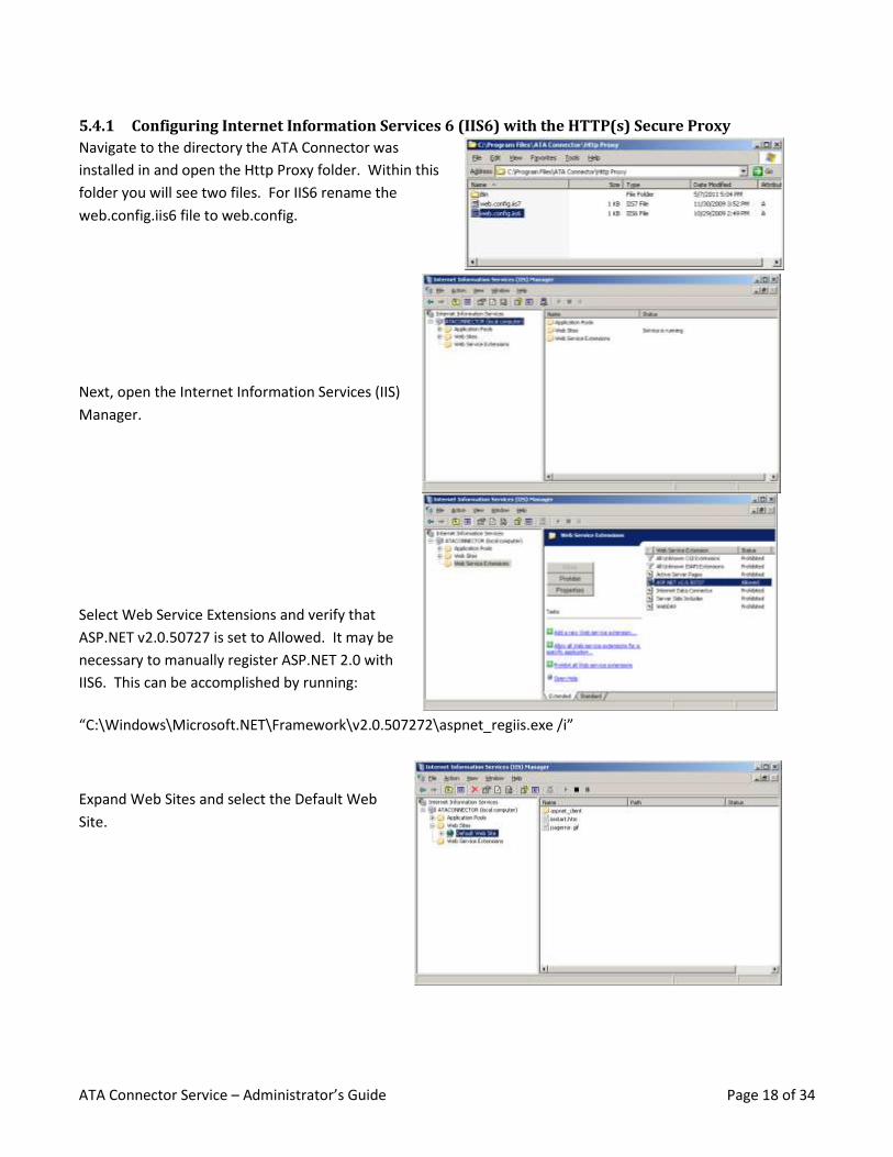
Navigate to the directory the ATA Connector was
installed in and open the Http Proxy folder. Within this
folder you will see two files. For IIS6 rename the
web.config.iis6 file to web.config.
Next, open the Internet Information Services (IIS)
Manager.
Select Web Service Extensions and verify that
ASP.NET v2.0.50727 is set to Allowed. It may be
necessary to manually register ASP.NET 2.0 with
IIS6. This can be accomplished by running:
“C:\Windows\Microsoft.NET\Framework\v2.0.507272\aspnet_regiis.exe /i”
Expand Web Sites and select the Default Web
Site.
ATA Connector Service – Administrator’s Guide Page 19 of 34
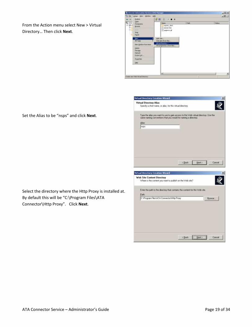
From the Action menu select New > Virtual
Directory… Then click Next.
Set the Alias to be “nsps” and click Next.
Select the directory where the Http Proxy is installed at.
By default this will be “C:\Program Files\ATA
Connector\Http Proxy”. Click Next.
ATA Connector Service – Administrator’s Guide Page 20 of 34
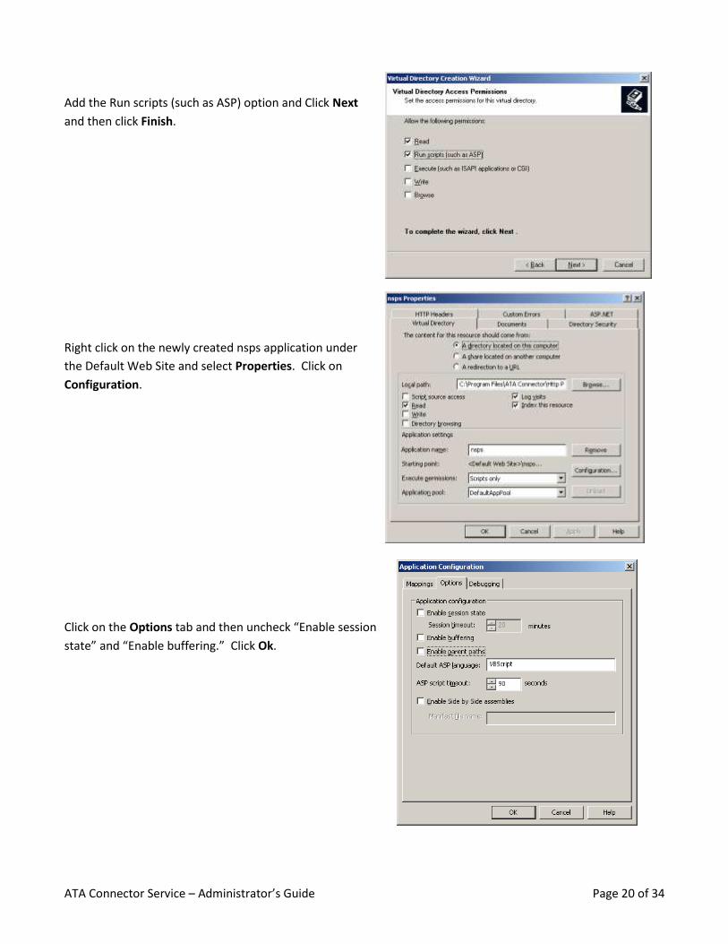
Add the Run scripts (such as ASP) option and Click Next
and then click Finish.
Right click on the newly created nsps application under
the Default Web Site and select Properties. Click on
Configuration.
Click on the Options tab and then uncheck “Enable session
state” and “Enable buffering.” Click Ok.
ATA Connector Service – Administrator’s Guide Page 21 of 34
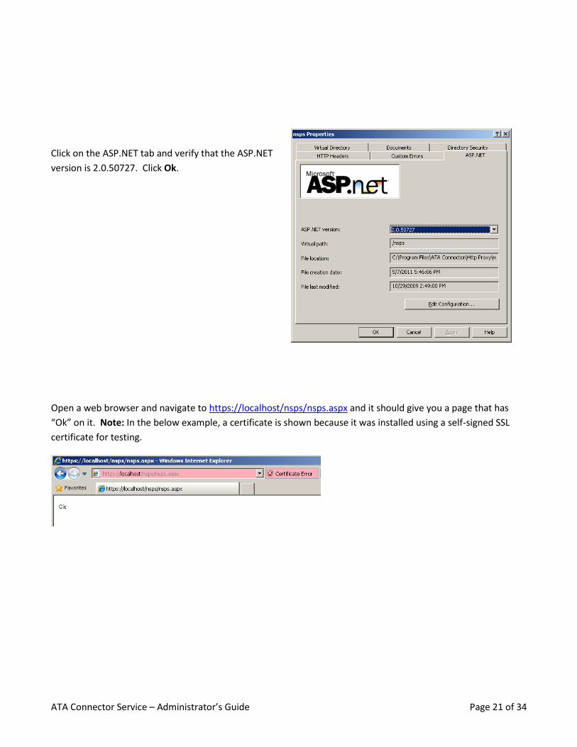
Click on the ASP.NET tab and verify that the ASP.NET
version is 2.0.50727. Click Ok.
Open a web browser and navigate to https://localhost/nsps/nsps.aspx and it should give you a page that has
“Ok” on it. Note: In the below example, a certificate is shown because it was installed using a self-signed SSL
certificate for testing.
ATA Connector Service – Administrator’s Guide Page 22 of 34
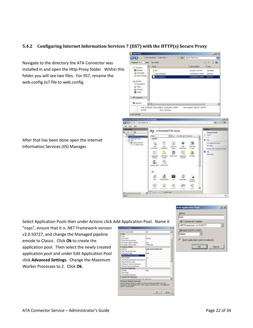
5.4.2 Configuring Internet Information Services 7 (IIS7) with the HTTP(s) Secure Proxy
Navigate to the directory the ATA Connector was
installed in and open the Http Proxy folder. Within this
folder you will see two files. For IIS7, rename the
web.config.iis7 file to web.config.
After that has been done open the Internet
Information Services (IIS) Manager.
Select Application Pools then under Actions click Add Application Pool. Name it
“nsps”, ensure that it is .NET Framework version
v2.0.50727, and change the Managed pipeline
emode to Classic. Click Ok to create the
application pool. Then select the newly created
application pool and under Edit Application Pool
click Advanced Settings. Change the Maximum
Worker Processes to 2. Click Ok.
ATA Connector Service – Administrator’s Guide Page 23 of 34
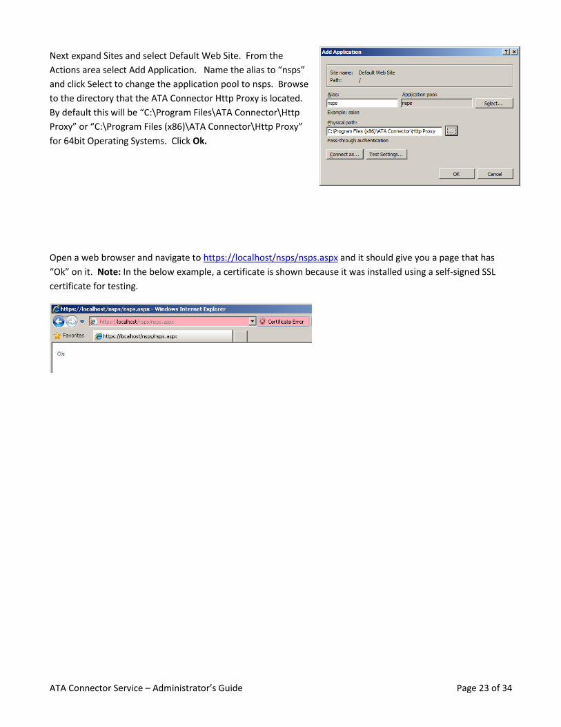
Next expand Sites and select Default Web Site. From the
Actions area select Add Application. Name the alias to “nsps”
and click Select to change the application pool to nsps. Browse
to the directory that the ATA Connector Http Proxy is located.
By default this will be “C:\Program Files\ATA Connector\Http
Proxy” or “C:\Program Files (x86)\ATA Connector\Http Proxy”
for 64bit Operating Systems. Click Ok.
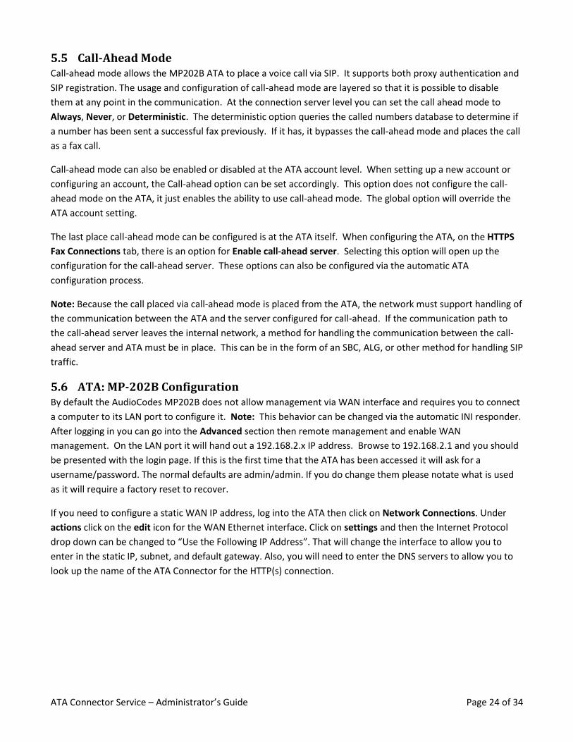
Open a web browser and navigate to https://localhost/nsps/nsps.aspx and it should give you a page that has
“Ok” on it. Note: In the below example, a certificate is shown because it was installed using a self-signed SSL
certificate for testing.
ATA Connector Service – Administrator’s Guide Page 24 of 34
5.5 Call-Ahead Mode Call-ahead mode allows the MP202B ATA to place a voice call via SIP. It supports both proxy authentication and
SIP registration. The usage and configuration of call-ahead mode are layered so that it is possible to disable
them at any point in the communication. At the connection server level you can set the call ahead mode to
Always, Never, or Deterministic. The deterministic option queries the called numbers database to determine if
a number has been sent a successful fax previously. If it has, it bypasses the call-ahead mode and places the call
as a fax call.
Call-ahead mode can also be enabled or disabled at the ATA account level. When setting up a new account or
configuring an account, the Call-ahead option can be set accordingly. This option does not configure the call-
ahead mode on the ATA, it just enables the ability to use call-ahead mode. The global option will override the
ATA account setting.
The last place call-ahead mode can be configured is at the ATA itself. When configuring the ATA, on the HTTPS
Fax Connections tab, there is an option for Enable call-ahead server. Selecting this option will open up the
configuration for the call-ahead server. These options can also be configured via the automatic ATA
configuration process.
Note: Because the call placed via call-ahead mode is placed from the ATA, the network must support handling of
the communication between the ATA and the server configured for call-ahead. If the communication path to
the call-ahead server leaves the internal network, a method for handling the communication between the call-
ahead server and ATA must be in place. This can be in the form of an SBC, ALG, or other method for handling SIP
traffic.
5.6 ATA: MP-202B Configuration By default the AudioCodes MP202B does not allow management via WAN interface and requires you to connect
a computer to its LAN port to configure it. Note: This behavior can be changed via the automatic INI responder.
After logging in you can go into the Advanced section then remote management and enable WAN
management. On the LAN port it will hand out a 192.168.2.x IP address. Browse to 192.168.2.1 and you should
be presented with the login page. If this is the first time that the ATA has been accessed it will ask for a
username/password. The normal defaults are admin/admin. If you do change them please notate what is used
as it will require a factory reset to recover.
If you need to configure a static WAN IP address, log into the ATA then click on Network Connections. Under
actions click on the edit icon for the WAN Ethernet interface. Click on settings and then the Internet Protocol
drop down can be changed to “Use the Following IP Address”. That will change the interface to allow you to
enter in the static IP, subnet, and default gateway. Also, you will need to enter the DNS servers to allow you to
look up the name of the ATA Connector for the HTTP(s) connection.
ATA Connector Service – Administrator’s Guide Page 25 of 34
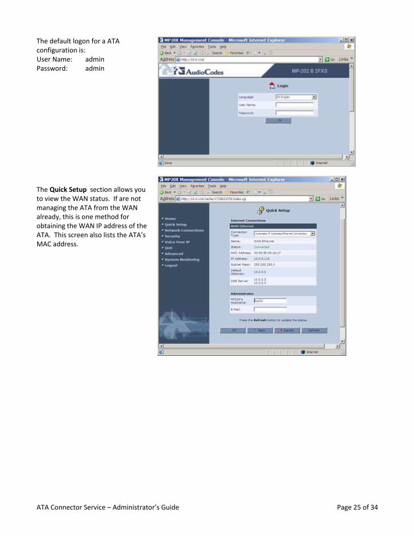
The default logon for a ATA configuration is: User Name: admin Password: admin
The Quick Setup section allows you to view the WAN status. If are not managing the ATA from the WAN already, this is one method for obtaining the WAN IP address of the ATA. This screen also lists the ATA’s MAC address.
ATA Connector Service – Administrator’s Guide Page 26 of 34
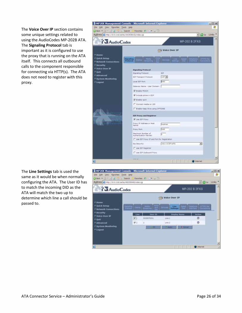
The Voice Over IP section contains some unique settings related to using the AudioCodes MP-202B ATA. The Signaling Protocol tab is important as it is configured to use the proxy that is running on the ATA itself. This connects all outbound calls to the component responsible for connecting via HTTP(s). The ATA does not need to register with this proxy.
The Line Settings tab is used the same as it would be when normally configuring the ATA. The User ID has to match the incoming DID as the ATA will match the two up to determine which line a call should be passed to.

ATA Connector Service – Administrator’s Guide Page 27 of 34
The main configuration for using an AudioCodes MP202B ATA with the ATA Connector is within the HTTPS Fax Connections tab. This is where you configure the User Name, Password, and Server logon url that are configured at the ATA Connector. The advanced options are for the embedded application and should not be changed unless you update other related settings. The Call ahead settings allow you to make voice calls on the same ATA that you use for fax calls. The exact configuration and what is required to exist for this to function correctly is discussed in the Call-Ahead Mode section of this manual.
5.6.1 Basic ATA Setup
For use with the ATA Connector, the MP202B with HTTP(s) support will only need to have a few settings
adjusted. The majority of these are contained on the HTTPS Fax Connections tab of the web configuration site.
5.6.2 Finding the ATAs IP Address
In order to manually configure an ATA, the administrator must be able to connect to the configuration interface
of the ATA, which requires finding its IP address on a network. The default behavior of the ATA is to obtain the
IP address information via DHCP.
There are three mechanisms for find the IP address of a specific ATA.
1) Lift the handset, dialing *2*#, and listening for voice prompt containing the IP address.
2) Connect another computer to the LAN port of the ATA and access IP: 192.168.2.1.
3) From the ATA Connector, list the Database records for connected ATA’s.
5.6.3 Entering the PIN on the ATA
There are two standard methods for configuring the password for an ATA account. It is important to understand
that this password is NOT the administrative password for accessing and configuring the ATA, but rather the
password which will be provided to the mail service provider for accessing the ATA’s designated mailbox.
ATA Connector Service – Administrator’s Guide Page 28 of 34
Methods for configuring fax account password:
1) Via HTTPS Fax Connections tab in ATA web configuration.
2) Via phone numeric keypad on the fax machine by dialing *1*{numeric password}#
5.7 Entering HTTP(s) Connection Information Log into the ATA, you can find the IP address by following the steps in Section 5.6.2, and click on Voice over IP
on the left. Select the HTTPS Fax Connections tab. Fill in the User Name, Password, and Server logon url. The
User Name and Password are configured within the web administration when the account is created or
modified. The Server logon url can be obtained from the Home screen within the web administration.
5.8 Manual ATA Configuration Log into the ATA, you can find the IP address by following the steps in Section 5.6.2 for logging into the ATA web
configuration, and click on Voice over IP on the left.
On the Signaling Protocol tab configure the following options:
Use SIP Proxy: Check
Proxy IP Address or Host Name: 127.0.0.1
Proxy Port: 5066
Use SIP Proxy IP and Port for Registration – Uncheck
Use SIP Registrar – Uncheck
All other options should be left at the defaults.
Within the Voice and Fax tab please ensure that the following options are configured:
Enable Silence Compression: Unchecked
Fax Transport Mode: T.38 Relay
Error Correction Mode: Checked
Switch To Fax Only By The Answering Side: Checked
On the Line Settings tab, enable or disable lines so that it matches the account configuration within the
AudioCodes ATA Connector. After that is configured, edit the line(s) and set the User ID to be the DID from the
account within the ATA Connector.
The last part to configure within the ATA is the HTTPS Fax Connections Tab. If this tab does not appear you may
have to telnet into the device (telnet 192.168.2.1) and enter the username/password (admin/admin by default).
After you are presented with the “Gateway>” prompt enter the following command:
rg_conf_set /voip/pfax/enabled 1
Then refresh the web interface and you should see the HTTPS Fax Connections tab. On this tab you will
configure the following options:
User Name: Account Name from the ATA Account within AudioCodes ATA connector
Password: Password from the ATA Account within AudioCodes ATA connector
Server logon url: This is the client login url from the ATA Connector Setup.
ATA Connector Service – Administrator’s Guide Page 29 of 34
5.8.1 Automatic ATA Provisioning
The MP202B is designed for fully automatic provisioning for enterprises which are large enough to justify tightly
controlling this process. Devices shipped from the factory are set to seek updates and default configuration
from https://faxata.com/{MAC Address}.
There are three models for controlling the provisioning process:
1) Registration of MAC Address with AudioCodes for redirection to desired provisioning site.
2) Private DNS override of provisioning site.
3) Manual ATA configuration change to corporate provisioning site.
Please reference the AudioCodes MP202B Fax Connector Technical Reference Guide for further details.
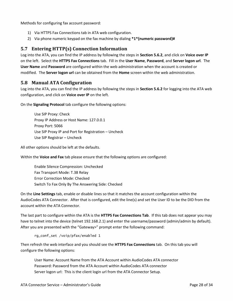
5.9 Web Administration This is the login screen of the AudioCodes Fax
ATA Connector. It can be accessed by going
to Start > Programs > ATA Connector >
Administration or by browsing to
http://<ataconnector>: 63/ where
<ataconnector> is the name of the server
that the ATA Connector is installed on. To log
in use the credentials entered during setup.
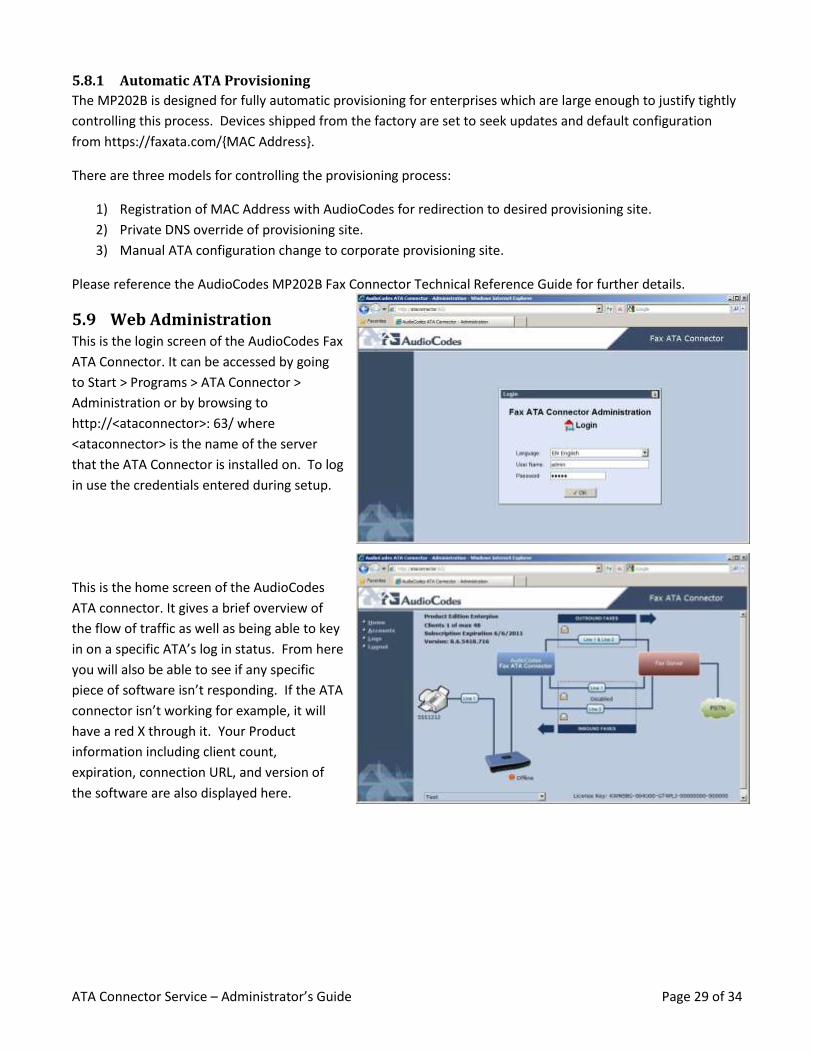
This is the home screen of the AudioCodes
ATA connector. It gives a brief overview of
the flow of traffic as well as being able to key
in on a specific ATA’s log in status. From here
you will also be able to see if any specific
piece of software isn’t responding. If the ATA
connector isn’t working for example, it will
have a red X through it. Your Product
information including client count,
expiration, connection URL, and version of
the software are also displayed here.
ATA Connector Service – Administrator’s Guide Page 30 of 34
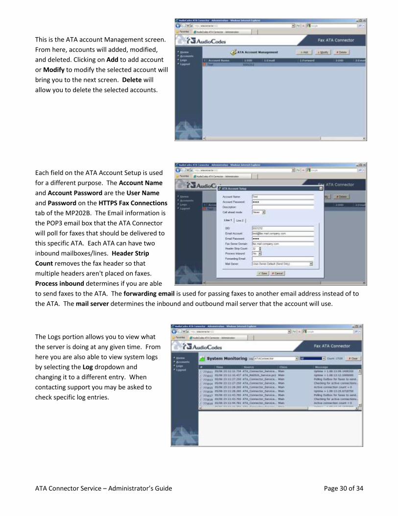
This is the ATA account Management screen.
From here, accounts will added, modified,
and deleted. Clicking on Add to add account
or Modify to modify the selected account will
bring you to the next screen. Delete will
allow you to delete the selected accounts.
Each field on the ATA Account Setup is used
for a different purpose. The Account Name
and Account Password are the User Name
and Password on the HTTPS Fax Connections
tab of the MP202B. The Email information is
the POP3 email box that the ATA Connector
will poll for faxes that should be delivered to
this specific ATA. Each ATA can have two
inbound mailboxes/lines. Header Strip
Count removes the fax header so that
multiple headers aren't placed on faxes.
Process inbound determines if you are able
to send faxes to the ATA. The forwarding email is used for passing faxes to another email address instead of to
the ATA. The mail server determines the inbound and outbound mail server that the account will use.
The Logs portion allows you to view what
the server is doing at any given time. From
here you are also able to view system logs
by selecting the Log dropdown and
changing it to a different entry. When
contacting support you may be asked to
check specific log entries.

ATA Connector Service – Administrator’s Guide Page 31 of 34
6 Maintenance Tasks The following maintenance tasks should be performed on a periodic basis.
1) Examine Windows Event Logs for warning or error messages which may indicate problems which might
otherwise go unreported.
2) If a significant number of add / removes has taken place for ATA accounts it is recommended that the
“real-time” ATA connector table be purged. This will eliminate accounts which are no longer active from
being polled for receive messages and notifications.
3) Manual configuration for Call-Ahead mode for a particular Fax destination.
4) Backup of the Call-Ahead Fax number database.
5) Backup of service configuration.
6) Checking for driver updates.
6.1 Starting & Stopping ATA Connector There are two ways to start or stop the ATA Connector services.
1) Via the Windows Services Control
2) Via the Configuration application.
The ATA Connector has three independent services:
ATAConnectionService
ATAQueueServer
ATAT37Connector
To start or stop ATA Connector services via the standard Windows Services control:
1) Via Start Menu, Select Control Panel
2) Select Administrative Tools
3) Select Services
4) Select the desired service.
ATA Connector Service – Administrator’s Guide Page 32 of 34
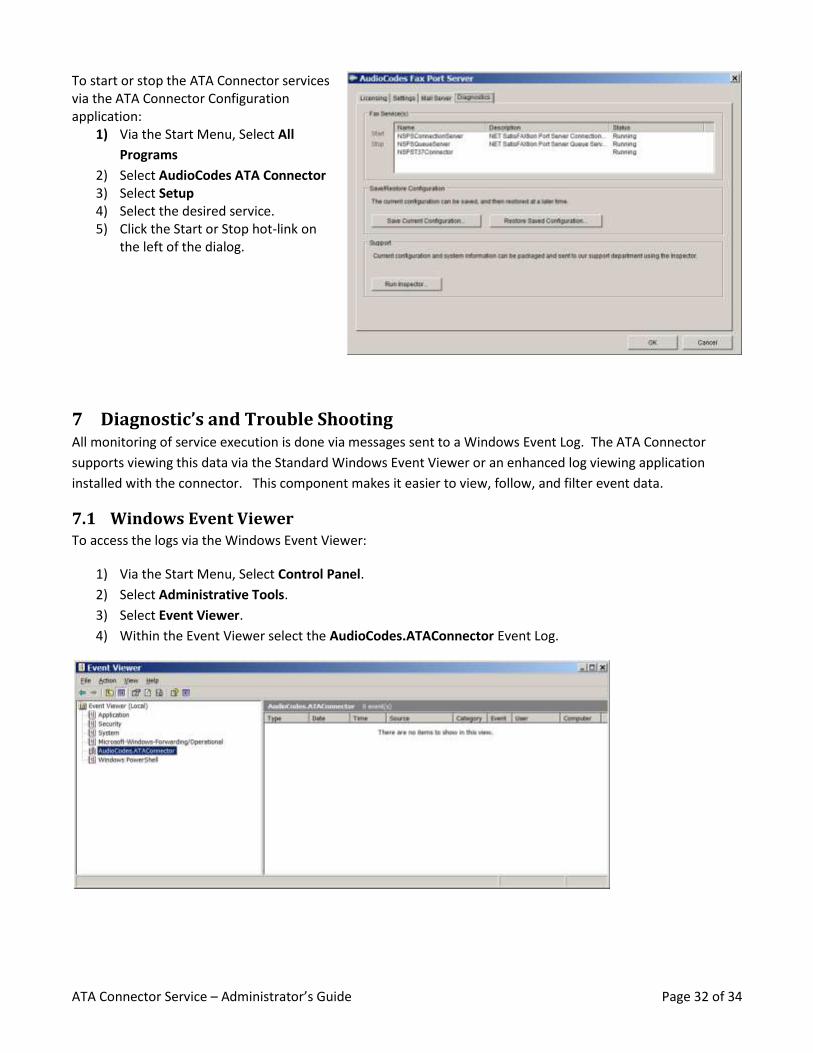
To start or stop the ATA Connector services via the ATA Connector Configuration application:
1) Via the Start Menu, Select All
Programs
2) Select AudioCodes ATA Connector 3) Select Setup 4) Select the desired service. 5) Click the Start or Stop hot-link on
the left of the dialog.
7 Diagnostic’s and Trouble Shooting All monitoring of service execution is done via messages sent to a Windows Event Log. The ATA Connector
supports viewing this data via the Standard Windows Event Viewer or an enhanced log viewing application
installed with the connector. This component makes it easier to view, follow, and filter event data.
7.1 Windows Event Viewer To access the logs via the Windows Event Viewer:
1) Via the Start Menu, Select Control Panel.
2) Select Administrative Tools.
3) Select Event Viewer.
4) Within the Event Viewer select the AudioCodes.ATAConnector Event Log.

ATA Connector Service – Administrator’s Guide Page 33 of 34
7.2 Log Viewer While the Windows Event log viewer is standardized and consistently available in all Windows operating
environments, the included Log Viewer provides easier viewing of more detailed information than is readily
available within the standard viewer.
To access the logs via the enhanced log viewer: 1) Via the Start Menu, Select All Programs. 2) Select AudioCodes ATA Connector. 3) Select Log Viewer 4) Select File Open Remote 5) Accept default host:
http://localhost:88/LoggingService
7.3 ATA Audio Error Messages These messages will be presented to the user as audio during the initial setup of the fax call. Each message will
also contain an error code that can be used to troubleshoot further.
1) Unable to contact server
2) Server busy or unavailable
3) Unable to login
4) Account suspected duplicate
5) Account send disabled
6) Dial number blocked
7) Dial number invalid
8) Send time expired
9) Your fax cannot be delivered.
7.4 IPFS Manager IPFS Manager is tool useful in troubleshooting. The individual components can be viewed and the status of each
evaluated. To open IPFS Manager, browse to the directory that the ATA Connector is installed in and run the
IPFSManager.exe program. Each component offers a right click menu that allows access to its sub items.
The Connection Server Allows you to see which ATAs are logged in under Manage Accounts. The Active Sessions
show you what send and receive sessions are currently active. The Activity Log will show you the login attempts
and other entries related to the function of the Connection Server. The Client Logs are how you access the logs
that the ATAs have uploaded to the server. The Called Numbers will show you which numbers have been called.
The Properties of the Connection Server are generally unused except if you are configuring one of the advanced
server setups.
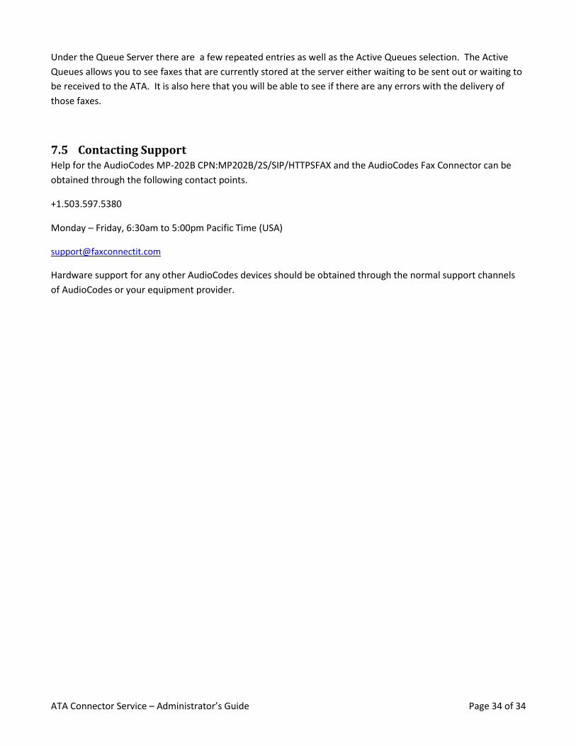
ATA Connector Service – Administrator’s Guide Page 34 of 34
Under the Queue Server there are a few repeated entries as well as the Active Queues selection. The Active
Queues allows you to see faxes that are currently stored at the server either waiting to be sent out or waiting to
be received to the ATA. It is also here that you will be able to see if there are any errors with the delivery of
those faxes.
7.5 Contacting Support Help for the AudioCodes MP-202B CPN:MP202B/2S/SIP/HTTPSFAX and the AudioCodes Fax Connector can be
obtained through the following contact points.
+1.503.597.5380
Monday – Friday, 6:30am to 5:00pm Pacific Time (USA)
Hardware support for any other AudioCodes devices should be obtained through the normal support channels
of AudioCodes or your equipment provider.