AUDIO VIDEO SURROUND RECEIVER KRF-V6090Dmanual.kenwood.com/files/B60-5532-00_En.pdf · LOGIC II...
36
ITALIANO DEUTSCH FRANÇAIS ENGLISH ESPAÑOL NEDERLANDS AUDIO VIDEO SURROUND RECEIVER KRF-V6090D KRF-V5090D INSTRUCTION MANUAL KENWOOD CORPORATION B60-5532-00 01 CS (E) 0409 About the supplied remote control Compared to standard remote controls, the remote control supplied with this model has several operation modes. These modes enable the remote control to control other KENWOOD DVD players. In order to effectively use the remote control it is important to read the operating instructions and obtain a proper understanding of the remote control and how to switch its operation modes (etc.). Using the remote control without completely understanding its design and how to switch the operation modes may result in incorrect operations. This instruction manual is for some models. Model availability and features (functions) may differ depending on the country and sales area.
Transcript of AUDIO VIDEO SURROUND RECEIVER KRF-V6090Dmanual.kenwood.com/files/B60-5532-00_En.pdf · LOGIC II...
ITA
LIA
NO
DE
UT
SC
HFR
AN
ÇA
ISE
NG
LIS
HE
SPA
ÑO
LN
ED
ER
LA
ND
S
AUDIO VIDEO SURROUND RECEIVER
KRF-V6090DKRF-V5090DINSTRUCTION MANUALKENWOOD CORPORATION
B60-5532-00 01 CS (E) 0409
About the supplied remote controlCompared to standard remote controls, the remote control supplied with this model has several operationmodes. These modes enable the remote control to control other KENWOOD DVD players. In order toeffectively use the remote control it is important to read the operating instructions and obtain a properunderstanding of the remote control and how to switch its operation modes (etc.).Using the remote control without completely understanding its design and how to switch the operationmodes may result in incorrect operations.
This instruction manual is for some models. Model availability and features
(functions) may differ depending on the country and sales area.
5532/01-06/EN 05.2.16, 9:47 AM1

2 EN
EN
GL
ISH
Before applying the power Caution : Read this page carefully to ensure safeoperation.
How to use this manualThis manual is divided into four sections, Preparations, Operations,Remote Control, and Additional Information.
PreparationsShows you how to connect your audio and video components to thismodel and prepare the surround processor.Since this model works with all of your audio and video components, wewill guide you in setting up your system to be as easy as possible.
OperationsShows you how to operate the various functions available on this model.
Remote ControlShows you how to operate other components using the remote control,as well as a detailed explanation of all remote control operations. Onceyou have setup the remote control, you’ll be able to operate both thismodel and your KENWOOD DVD player using the remote controlsupplied with this model.
Additional InformationShows you additional information such as “In case of difficulty”(troubleshooting) and “Specifications”.
Units are designed for operation as follows.
U.S.A. and Canada ........................................... AC 120 V only
Australia ........................................................... AC 240 V only
Europe and U.K. ............................................... AC 230 V only
China and Russia ............................................. AC 220 V only
Other countries ............ AC 110-120 / 220-240 V switchable
Maintenance of the unitWhen the front panel or case becomes dirty, wipe with a soft, drycloth. Do not use thinner, benzine, alcohol, etc. for these agents maycause discoloration.
In regard to contact cleanerDo not use contact cleaner because it could cause a malfunction. Bespecially careful not to use contact cleaners containing oil, for theymay deform the plastic component.
UnpackingUnpack the unit carefully and make sure that all accessories are
present.
FM indoor antenna (1) AM loop antenna (1)
Remote control unit (1) Batteries (R03/AAA) (2)RC-R0630E
If any accessories are missing, or if the unit is damaged or fails to operate,notify your dealer immediately. If your unit was shipped to you directly,notify your shipper immediately. Kenwood recommend that you retainthe original carton and packing materials in case you needs to move orship the unit in the future.Keep this manual handy for future reference.
Memory back up function
Please note that the following items will be deleted from the unit'smemory if the power cord is disconnected from the AC outlet forapproximately 1 day.• Power mode• Input selector settings• Picture output• Speaker ON/OFF• Volume level• BASS, TREBLE, INPUT level• TONE ON/OFF• LOUDNESS ON/OFF• ACTIVE EQ mode• Dimmer level
• MD/TAPE settings• Input mode setting• Speaker settings• Sound mode settings• Distance setting• Listen mode setting• Broadcast band• Frequency setting• Preset stations• Tuning mode
Safety precautions
WARNING :
TO PREVENT FIRE OR ELECTRIC SHOCK,DO NOT EXPOSE THIS APPLIANCE TORAIN OR MOISTURE.
CAUTIONRISK OF ELECTRIC SHOCK
DO NOT OPEN
CAUTION: TO REDUCE THE RISK OF ELECTRIC SHOCK, DO NOTREMOVE COVER (OR BACK). NO USER-SERVICEABLE PARTSINSIDE. REFER SERVICING TO QUALIFIED SERVICE PERSONNEL.
THE LIGHTNING FLASH WITH ARROWHEAD SYMBOL,WITHIN AN EQUILATERAL TRIANGLE, IS INTENDED TOALERT THE USER TO THE PRESENCE OF UNINSULATED“DANGEROUS VOLTAGE” WITHIN THE PRODUCT’SENCLOSURE THAT MAY BE OF SUFFICIENT MAGNITUDETO CONSTITUTE A RISK OF ELECTRIC SHOCK TOPERSONS.
THE EXCLAMATION POINT WITHIN AN EQUILATERALTRIANGLE IS INTENDED TO ALERT THE USER TO THEPRESENCE OF IMPORTANT OPERATING ANDMAINTENANCE (SERVICING) INSTRUCTIONS IN THELITERATURE ACCOMPANYING THE APPLIANCE.
*5532/01-06/EN 04.11.23, 12:592
3 EN
EN
GL
ISH
Before applying the power ...................................................... 2Safety precautions ..................................................................... 2Unpacking .................................................................................. 2Preparing the remote control ..................................................... 3Special features ......................................................................... 4
Names and functions of parts ................................................. 5Main Unit .................................................................................... 5Remote control unit ................................................................... 6
Setting up the system ........................................ 7Connecting a DVD player (6-channel input) ....... 8Connecting audio components .......................... 9Connecting video components ........................ 10Connecting video components (COMPONENTVIDEO) (KRF-V6090D only) .............................. 11Digital connections .......................................... 12Connecting the speakers ................................. 13Connecting the terminals ................................ 14Connecting the antennas ................................. 14
Preparing for surround sound ....................... 15Speaker settings .............................................. 15
Normal playback.............................................. 18Preparing for playback ..................................... 18Listening to a source component .................... 18Adjusting the sound ......................................... 19
Recording .......................................................... 20Recorning audio (analog sources) ................... 20Recording video ............................................... 20Recording audio (digital sources) .................... 20
Listening to radio broadcasts ....................... 21Tuning (non-RDS) radio stations ...................... 21Using RDS (Radio Data System) ..................... 21Presetting radio stations manually .................. 22Receiving preset stations ................................ 22Receiving preset stations in order (P.CALL) ... 23Using the RDS DISP. (Display) key ................. 23Presetting RDS stations(RDS AUTO MEMORY) ................................... 24Tuning by Program TYpe (PTY search) ............ 24
Ambience effects ............................................. 25Surround modes .............................................. 25Surround play ................................................... 27DVD 6-channel playback .................................. 28Convenient functions ....................................... 29
Basic remote control operations for KENWOODDVD players ...................................................... 31
DVD player operation keys .............................. 31
In case of difficulty .......................................... 33Specifications .................................................. 35
Contents
Caution : Read the pages marked carefully to ensuresafe operation.
Before applying the power
Preparations
Operations
AdditionalInformation
RemoteControl
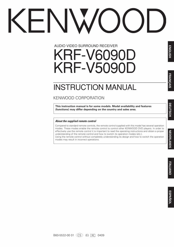
Operating range
(Approx.)Remote sensor
Infrared ray system
6 m
RECEIVER
Operation
When the STANDBY indicator is lit, the power turns ON when you pressthe RECEIVER key on the remote control unit. When the power comesON, press the key you want to operate.
• When pressing more than one remote control key successively,press the keys securely by leaving an interval of 1 second or morebetween keys.
Notes1. The supplied batteries may have shorter lives than ordinary batteries
due to use during operation checks.2. When the remote-controllable distance gets shorter than before,
replace both batteries with new ones.3. Placing the remote sensor in direct sunlight, or in direct light from a
high frequency fluorescent lamp may cause a malfunction.In such a case, change the location of the system installation toprevent malfunction.
Preparing the remote control
Loading the batteries1 Remove the cover. 2 Insert the batteries.
3 Close the cover.
• Insert two AAA-size (R03) batteries as indicated by the polaritymarkings.
*5532/01-06/EN 04.11.23, 12:593
4 EN
EN
GL
ISH
Before applying the power
Special features
True home theater soundThis model incorporates a wide variety of surround modes to bring youmaximum enjoyment from your video software. Select a surround modeaccording to your equipment or the software you are going to play andenjoy! ∞
Dolby Digital and Dolby Digital EXThe DOLBY DIGITAL mode lets you enjoy full digital surround fromsoftware processed in the Dolby Digital format. Dolby Digital provides upto 5.1 channels of independent digital audio for better sound quality andmore powerful presence than conventional Dolby Surround. As for DolbyDigital EX, it creates six full-bandwidth output channels from the 5.1channel sources. This is done using a matrix decoder that derives threesurround channels from the two in the original recording. For best result,Dolby Digital EX should be used with movie soundtracks recorded withDolby Digital Surround EX.
Dolby PRO LOGIC IIx and Dolby PRO LOGIC IIDOLBY PRO LOGIC II, whilst totally compatible with its predecessorPRO LOGIC, provides greater advantages in surround sound. It allowsuser to enjoy the conventional stereo or Dolby Surround with a convincing“5.1 like” presentation. PRO LOGIC II offers special features for controllingthe overall spatial, dimensionality and frontal sound field imaging. PROLOGIC II produces an impressive surround sound from video softwaremarked and three-dimensional space from music CD.When listening to music, you will be able to enjoy the experience of sheerSTEREO surround sound.DOLBY PRO LOGIC IIx enhanced DOLBY PRO LOGICII’s features.It creates 6.1 channel and 7.1 channel surround sound from stereo or 5.1channel signals. This feature provides you an astonishing ambienceeffect which makes you feel you are surrounded by natural sound.Especially 7.1 channel surround sound can produce real back sound fromSurround Back speakers.
DTS and DTS-ESDTS (Digital Theater System) is a 5.1 channel digital audio format thatprovides five full-spectrum channels and one low-frequency (subwoofer)channel for unprecedented clarity, optimum channel separation and a(wide) dynamic range.DTS-ES (Extended Surround) presents 6.1 channels surround systemwith additional Surround back channel which evolved from theconventional 5.1 channels surround system. DTS-ES format that wasrecorded in DVD, CD or LD comprises of two modes. DTS-ES Discrete6.1 produces the discrete surround back which is completely independentand DTS-ES Matrix 6.1 produces the surround back which synthesizedwithin the left and right surround channels using matrix technology. DTS-ES has perfect compatibility with the conventional 5.1 channels surroundsystem. 6.1 channels surround with an additional surround back presentsa more natural presence and surround effects by increasing the impressionof the sound image from back.
important:When a DTS disc is played on a CD, LD or DVD player, noise may beoutput from the analog output. It is recommended that you connect thedigital output of the player to the digital input of this unit.
Neo:6Neo:6 is a new technology which was developed by DTS. It can producehigh grade 6 channels surround with an astonishing fidelity from 2channels content. Neo:6 has 2 modes, “CINEMA” mode is for movieplayback and “MUSIC” mode is for music playback.
DSP surround modesThe DSP (Digital Signal Processor) used for this model incorporates avariety of high quality adjustable sound fields, like “ARENA”, “JAZZCLUB”, THEATER”, STADIUM” and “DISCO”. It is compatible withalmost any kind of program source.
DVD 6-channel inputIf you own a DVD player equipped with 6-channel output, this modelallows you to obtain the full surround sound impact of DVD sourcematerial featuring multi-channel encoding. Since the source signals aredigital and each channel is input independently, the resulting ambienceis far superior to what can be achieved with conventional surround soundsystems.
ACTIVE EQACTIVE EQ mode will produce a more dynamic sound quality in anycondition. You can enjoy a more impressive sound effect when ACTIVEEQ is turned on.
IR (InfraRed) remote controlIn addition to the basic receiver operations, this IR remote controlsupplied can also control KENWOOD DVD players directly without usingthe DVD Special features.
RDS (Radio Data System) tunerThis model is equipped with an RDS tuner that provides several convenienttuning functions: RDS Auto Memory, to automatically preset up to 40RDS stations broadcasting different programs; station name display, toshow you the name of the current broadcast station; and PTY search tolet you tune stations by program type.
PTY (Program TYpe) searchTune the stations by specifying the type of program you want to hear.
*5532/01-06/EN 04.11.23, 12:594
5 EN
EN
GL
ISH
Names and functions of parts
Main Unit
Standby mode
While the standby indicator is lit, a small amount of power is supplied tothe system to back-up the memory. This is called standby mode. Underthe condition, the system can be turned ON by the remote control unit.
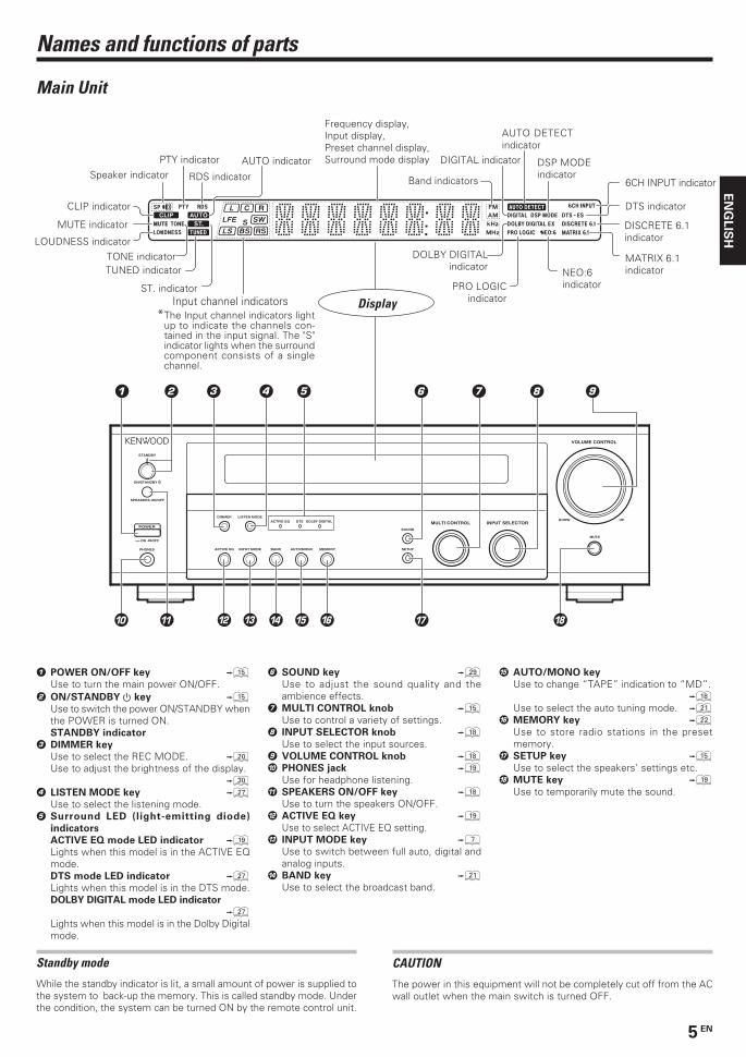
Display
Band indicators
Frequency display,Input display,Preset channel display,Surround mode display
Speaker indicator
PRO LOGICindicator
AUTO DETECTindicator
DOLBY DIGITALindicator
DTS indicatorCLIP indicator
ST. indicator
MUTE indicator
TONE indicatorLOUDNESS indicator
DSP MODEindicator
DIGITAL indicator
6CH INPUT indicatorRDS indicator
PTY indicator AUTO indicator
TUNED indicator
DISCRETE 6.1indicator
MATRIX 6.1indicatorNEO:6
indicator
CAUTION
The power in this equipment will not be completely cut off from the ACwall outlet when the main switch is turned OFF.
1 POWER ON/OFF key %Use to turn the main power ON/OFF.
2 ON/STANDBY key %Use to switch the power ON/STANDBY whenthe POWER is turned ON.STANDBY indicator
3 DIMMER key
Use to select the REC MODE. )Use to adjust the brightness of the display.
º4 LISTEN MODE key 
Use to select the listening mode.5 Surround LED (light-emitting diode)
indicators
ACTIVE EQ mode LED indicator (Lights when this model is in the ACTIVE EQmode.DTS mode LED indicator ¶Lights when this model is in the DTS mode.DOLBY DIGITAL mode LED indicator
¶Lights when this model is in the Dolby Digitalmode.
6 SOUND key ªUse to adjust the sound quality and theambience effects.
7 MULTI CONTROL knob %Use to control a variety of settings.
8 INPUT SELECTOR knob *Use to select the input sources.
9 VOLUME CONTROL knob *0 PHONES jack (
Use for headphone listening.! SPEAKERS ON/OFF key *
Use to turn the speakers ON/OFF.@ ACTIVE EQ key (
Use to select ACTIVE EQ setting.# INPUT MODE key 7
Use to switch between full auto, digital andanalog inputs.
$ BAND key ¡Use to select the broadcast band.
% AUTO/MONO key
Use to change “TAPE” indication to “MD”.*
Use to select the auto tuning mode. ¡^ MEMORY key ™
Use to store radio stations in the presetmemory.
& SETUP key %Use to select the speakers' settings etc.
* MUTE key (Use to temporarily mute the sound.
Input channel indicators*The Input channel indicators light
up to indicate the channels con-tained in the input signal. The "S"indicator lights when the surroundcomponent consists of a singlechannel.
ON OFF
POWER
PHONES
SPEAKERS ON/OFF
ON/STANDBY
STANDBY
ACTIVE EQ
ACTIVE EQ DTS DOLBY DIGITAL
INPUT MODE BAND AUTO/MONO MEMORY SETUP
MUTE
DOWN UPMULTI CONTROL INPUT SELECTOR
VOLUME CONTROL
SOUND
DIMMER LISTEN MODE
*5532/01-06/EN 04.11.23, 12:595

6 EN
EN
GL
ISH
Names and functions of parts
Remote control unit
CD/DVD MD/TAPE RECEIVER
DVD/6CHVIDEO 2VIDEO 1
DVD
SET UP
TONE
SOUNDDIMMER
MULTI CONTROLACTIVE EQLISTEN MODE
TOP MENU
RETURN ON SCREEN
MENU
ENTER
BAND
MUTE
BASS BOOST LOUDNESS DISC SEL. DISC SKIP
REPEATANGLESUBTITLEAUDIO
RDS DISP. PTY
1 Input Selector keys (TUNER, CD/DVD, MD/TAPE,
VIDEO 1, VIDEO 2, DVD/6CH, AUX) *Use to select the input sources.
2 Numeric keys
Use to operate the DVD player. ⁄Use to call up preset stations. ™
3 LISTEN MODE key ¶Use to select the listening mode.
4 ACTIVE EQ key (Use to select ACTIVE EQ setting.
5 %/fi/@/# keys
ENTER key
TOP MENU keyMENU keyRETURN keyON SCREEN key
Use to operate the DVD player. ⁄6 8 key ⁄
Use to operate the DVD player.BAND key ¡Use to select the broadcast band.6 key ⁄Use to operate the DVD player.AUTO/MONO key ¡Use to select the auto tuning mode.7 key ⁄Use to operate the DVD player.
7 P.CALL4/¢ keys
Use to call preset channel. £Use to operate the DVD player. ⁄
8 BASS BOOST key (Use to select the maximum adjustment setting forthe low frequency range.LOUDNESS key (Use to switch the status of LOUDNESS.
9 RECEIVER key %Use to turn this model on and off.
0 DVD key ⁄Use to turn on the DVD player on and off.
! SETUP key
Use to select the speakers’ settings etc. %Use to operate the DVD player. ⁄
@ TONE key (Use to switch the status of TONE control.
# SOUND key ªUse to adjust the sound quality and ambience effects.
$ DIMMER key
Use to adjust the brightness of the display. ªUse to operate the DVD player. ⁄
% MULTI CONTROL %/fi keys %Use to control a variety of settings.
^ VOLUME %/fi keys *Use to adjust volume setting.
& MUTE key (Use to temporarily mute the sound.
* TUNING 1/¡ keys
Use to select the radio station. ¡Use to operate the DVD player. ⁄
( RDS DISP. key £Use for RDS function.PTY key ¢Use for PTY search.DISC SEL. key
DISC SKIP key
AUDIO key
SUBTITLE key
ANGLE key
REPEAT key
Use to operate the DVD player. ⁄
• Some keys can be used for operating KENWOOD DVD players by pressing CD/DVD or DVD/6CH key beforehand. ⁄
5532/01-06/EN 05.2.16, 10:31 AM6
7 EN
EN
GL
ISH
Setting up the system
Make connections as shown in the following pages.
When connecting the related system components, be
sure to refer to the instruction manuals supplied with
the components you are connecting.
Do not connect the power cord to a wall outlet until all
connections are completed.
Notes1. Be sure to insert all connection cords securely. If their connections are
imperfect, the sound may not be produced or there will be noiseinterference.
2. Be sure to remove the power cord from the AC outlet before pluggingor unplugging any connection cords. Plugging/unplugging connectioncords without disconnecting the power cord can cause malfunctionsand may damage the unit.
3. Do not connect power cords from components whose powerconsumption is larger than what is indicated on the AC outlet at therear of this unit.
Analog connectionsAudio connections are made using RCA pin cords. These cables transferstereo audio signal in an “analog” form. This means the audio signalcorresponds to the actual audio of two channels. These cables usuallyhave 2 plugs at each end, red for the right channel and white for the leftchannel. These cables are usually packed together with the source unit,or are available at your local electronics retailer.
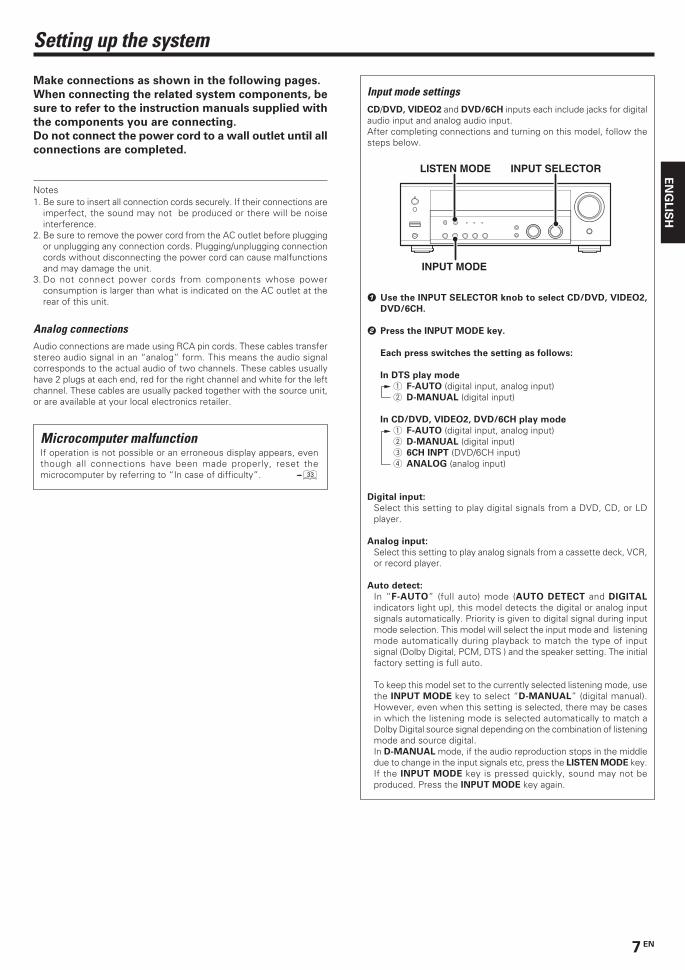
Input mode settingsCD/DVD, VIDEO2 and DVD/6CH inputs each include jacks for digitalaudio input and analog audio input.After completing connections and turning on this model, follow thesteps below.
1 Use the INPUT SELECTOR knob to select CD/DVD, VIDEO2,
DVD/6CH.
2 Press the INPUT MODE key.
Each press switches the setting as follows:
In DTS play mode
1 F-AUTO (digital input, analog input)2 D-MANUAL (digital input)
In CD/DVD, VIDEO2, DVD/6CH play mode
1 F-AUTO (digital input, analog input)2 D-MANUAL (digital input)3 6CH INPT (DVD/6CH input)4 ANALOG (analog input)
Digital input:
Select this setting to play digital signals from a DVD, CD, or LDplayer.
Analog input:
Select this setting to play analog signals from a cassette deck, VCR,or record player.
Auto detect:
In “F-AUTO” (full auto) mode (AUTO DETECT and DIGITAL
indicators light up), this model detects the digital or analog inputsignals automatically. Priority is given to digital signal during inputmode selection. This model will select the input mode and listeningmode automatically during playback to match the type of inputsignal (Dolby Digital, PCM, DTS ) and the speaker setting. The initialfactory setting is full auto.
To keep this model set to the currently selected listening mode, usethe INPUT MODE key to select “D-MANUAL” (digital manual).However, even when this setting is selected, there may be casesin which the listening mode is selected automatically to match aDolby Digital source signal depending on the combination of listeningmode and source digital.In D-MANUAL mode, if the audio reproduction stops in the middledue to change in the input signals etc, press the LISTEN MODE key.If the INPUT MODE key is pressed quickly, sound may not beproduced. Press the INPUT MODE key again.
INPUT MODE
INPUT SELECTORLISTEN MODE
Microcomputer malfunctionIf operation is not possible or an erroneous display appears, eventhough all connections have been made properly, reset themicrocomputer by referring to “In case of difficulty”. ‹
*5532/07-14/EN 04.11.25, 20:227
8 EN
EN
GL
ISH
CENTER
SUBWOOFER
SURROUNDFRONT
VIDEO 1OUT
VIDEO 1IN
VIDEO 2IN
DVDIN
MONITOROUT
VIDEO 2
DVD / 6CH
CD / DVDCOAXIAL OPTICALDVD / 6CH INPUTVIDEO
DIGITAL IN
DVDIN
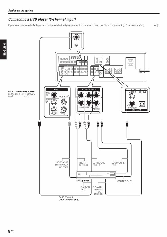
Setting up the system
Connecting a DVD player (6-channel input)If you have connected a DVD player to this model with digital connection, be sure to read the “Input mode settings” section carefully. 7
SURROUNDOUT L/R
VIDEO OUT(Yellow RCA
pin cord)
DVD player
SUBWOOFEROUT
CENTER OUT
FRONTOUT L/R
COAXIALDIGITAL
OUT(AUDIO)
S-VIDEOOUT
S-VIDEO cord(KRF-V6090D only)
For COMPONENT VIDEOconnection (KRF-V6090Donly) !
*5532/07-14/EN 04.11.25, 20:228
9 EN
EN
GL
ISH
Setting up the system
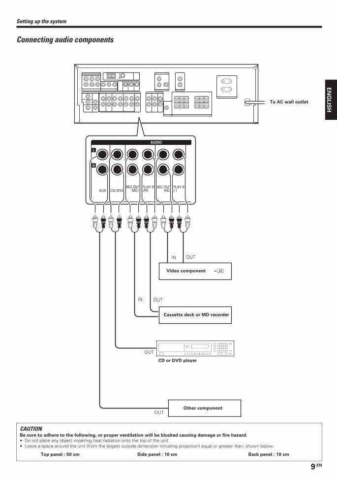
Connecting audio components
IN
OUTIN
OUT
OUT
OUT
To AC wall outlet
Cassette deck or MD recorder
CD or DVD player
Video component )
EUROPE
AUX CD/DVDREC OUT PLAY IN
VIDEO 1REC OUT PLAY IN
MD / TAPE
L
R
AUDIO
CAUTIONBe sure to adhere to the following, or proper ventilation will be blocked causing damage or fire hazard.
• Do not place any object impairing heat radiation onto the top of the unit.• Leave a space around the unit (from the largest outside dimension including projection) equal or greater than, shown below.
Top panel : 50 cm Side panel : 10 cm Back panel : 10 cm
Other component
*5532/07-14/EN 04.11.25, 20:229
10 EN
EN
GL
ISH
PLAY INVIDEO 2
REC OUT PLAY INVIDEO 1VIDEO 1
OUTVIDEO 1
IN
VIDEO 2IN
DVDIN MONITOR
OUT
VIDEO
AUDIO
VIDEO 2IN
DVDIN
MONITOROUT
S-VIDEO
Video deck
IN
Setting up the system
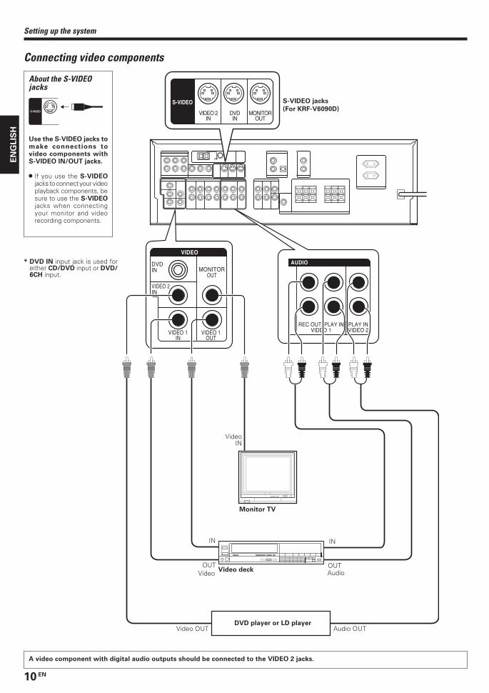
Connecting video components
A video component with digital audio outputs should be connected to the VIDEO 2 jacks.
Video AudioOUT OUT
Monitor TV
VideoIN
Video OUT
About the S-VIDEOjacks
S-VIDEO
Use the S-VIDEO jacks tomake connections tovideo components withS-VIDEO IN/OUT jacks.
• If you use the S-VIDEOjacks to connect your videoplayback components, besure to use the S-VIDEOjacks when connectingyour monitor and videorecording components.
Audio OUT
IN
S-VIDEO jacks
(For KRF-V6090D)
DVD player or LD player
* DVD IN input jack is used foreither CD/DVD input or DVD/6CH input.
*5532/07-14/EN 04.11.25, 20:2210

11 EN
EN
GL
ISH
PLAY INVIDEO 2
REC OUT PLAY INVIDEO 1
REC OUT PLAY INMD / TAPECD/DVD
AUDIO
MONITOR OUTY CB CR Y CB CR
DVD IN
COMPONENT VIDEOVIDEO 2 IN
DVD player
Setting up the system
Monitor TV
Video OUTAudio OUT
Video component
Video OUTAudio OUT
Connecting video components (COMPONENT VIDEO) (KRF-V6090D only)If you have connected the receiver to a video component with COMPONENT jacks, you can get a better picture quality than by connecting to the S-VIDEOjacks.
When connecting the TV to the COMPONENT jacks, be sure to connect all the other components to the COMPONENT jacks.
* DVD IN input jack is used foreither CD/DVD input or DVD/6CH input.
*5532/07-14/EN 04.11.25, 20:2211
12 EN
EN
GL
ISH
VIDEO 2
DVD / 6CH
CD / DVDCOAXIAL OPTICAL
DIGITAL IN
Setting up the system
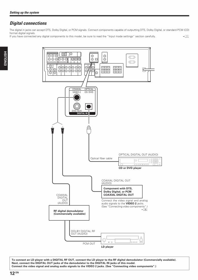
Digital connectionsThe digital in jacks can accept DTS, Dolby Digital, or PCM signals. Connect components capable of outputting DTS, Dolby Digital, or standard PCM (CD)format digital signals.If you have connected any digital components to this model, be sure to read the “Input mode settings” section carefully. 7
Component with DTS,
Dolby Digital, or PCM
COAXIAL DIGITAL OUTCOAXIALDIGITAL
OUT(AUDIO)
DOLBY DIGITAL RFOUT (AUDIO)
LD player
PCM OUT
RF digital demodulator(Commercially available)
CD or DVD player
OPTICAL DIGITAL OUT (AUDIO)Optical fiber cable
COAXIAL DIGITAL OUT(AUDIO)
Connect the video signal and analogaudio signals to the VIDEO 2 jacks.(See “Connecting video components”.)
0
To connect an LD player with a DIGITAL RF OUT, connect the LD player to the RF digital demodulator (Commercially available).
Next, connect the DIGITAL OUT jacks of the demodulator to the DIGITAL IN jacks of this model.
Connect the video signal and analog audio signals to the VIDEO 2 jacks. (See “Connecting video components”.)
*5532/07-14/EN 04.11.25, 20:2212
13 EN
EN
GL
ISH
CENTERFRONT
+
-
R L
RED WHITE GREEN
KRF-V5090D
SURROUND
+
-
R
GRAY
L
BLUE
SURROUNDBACKSURROUND
+
-
KRF-V6090D
R
GRAY
L
BLUE BROWN
SPEAKERS (6
SPEAKERS (6-16Ω)SPEAKERS (6-16Ω)
SUB WOOFER
PRE OUT
PRE OUT
SURR BACK L*
SURR BACK R PRE OUT
SURR BACK L/SURR BACK
SURR BACK R
KRF-V6090D
*KRF-V6090D:SURR BACK L/SURR BACK
Setting up the system
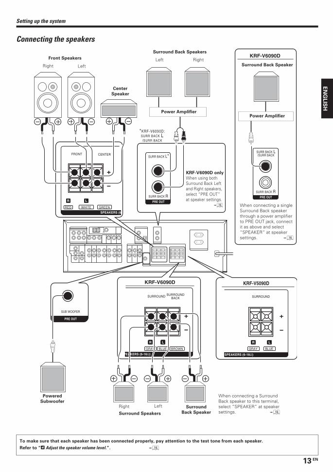
Connecting the speakers
Center
Speaker
Front Speakers
Right Left
Surround
Back Speaker
Powered
SubwooferRight Left
Surround Speakers
RightLeft
To make sure that each speaker has been connected properly, pay attention to the test tone from each speaker.
Refer to “4 Adjust the speaker volume level.”. ^
Power Amplifier
Surround Back Speakers
When connecting a SurroundBack speaker to this terminal,select “SPEAKER” at speakersettings. ^
Power Amplifier
Surround Back Speaker
When connecting a singleSurround Back speakerthrough a power amplifierto PRE OUT jack, connectit as above and select“SPEAKER” at speakersettings. ^
KRF-V6090D only
When using bothSurround Back Leftand Right speakers,select “PRE OUT”at speaker settings.
^
*5532/07-14/EN 04.11.25, 20:2213

14 EN
EN
GL
ISH
GNDAM FM75Ω
ANTENNA
Setting up the system
Connecting the antennasThe broadcast reception cannot be made unless the antennas areconnected. Connect the antennas correctly as instructed below.
AM loop antennaPlace the supplied loop antenna as far as possible from the receiver,TV set, speaker cords and power cord, and adjust the direction forbest reception.
FM indoor antennaThe supplied indoor antenna is for temporary use only. For stablesignal reception we recommend using an outdoor antenna. Disconnectthe indoor antenna when you connect one outdoors.
FM outdoor antennaLead the 75Ω coaxial cable connected to the FM outdoor antenna intothe room and connect it to the FM 75Ω terminal.
AM antenna terminal connections1 Push lever. 2 Insert cord. 3 Release lever.
FM antenna terminal connectionsInsert cord.
Use an antennaadapter(Commerciallyavailable)
Attach to thestand
AM loop antenna
FM indoor antenna
FM outdoor antenna
1 Strip coating. 2 Push the lever.
3 Insert the cord. 4 Return the lever.
Connecting the terminals
Speaker impedance
After confirming the speaker impedance indications printed on therear panel of this model, connect speakers with matching impedanceratings. Using speakers with a rated impedance other than thatindicated on the rear panel of this model could result in malfunctionsor damage to the speakers or this model.
• Never short circuit the + and – speaker cords.• If the left and right speakers are connected inversely or the speaker
cords are connected with reversed polarity, the sound will beunnatural with ambiguous acoustic imaging. Be sure to connect thespeakers correctly.
Speaker placement
*For Surround Back speaker, you may place either two SurroundBack speakers (Surround Back Left speaker and Surround BackRight speaker) for 7.1 channel surround sound system or oneSurround Back speaker for 6.1 channel surround sound system.
Front speakers : Place to the front left and right of the listeningposition. Front speakers are required for all surround modes.Center speaker : Place front and center. This speaker stabilizes thesound image and helps recreate sound motion. Required for surroundplayback.Surround speakers : Place to the direct left and right, or slightlybehind the listening position at even heights, approximately 1 meterabove the ears of the listeners. These speakers recreate soundmotion and atmosphere. Required for surround playback.Subwoofer : Reproduces powerful deep bass sounds.Surround Back speaker/s : Place the speaker/s directly at the rearof the listening position. The optimum position depends mainly on theroom condition.
• Although the ideal surround system consists of all the speakerslisted above, if you don't have a center speaker or a subwoofer, youcan divide those signals between the available speakers in thespeaker settings steps to obtain the best possible surroundreproduction from the speakers you have available. %
Frontspeaker
Subwoofer
Surroundspeaker
Center speaker
Listeningposition
*SurroundBack speaker
*SurroundBack Rightspeaker
*SurroundBack Leftspeaker
*5532/07-14/EN 04.11.26, 17:5714

15 EN
EN
GL
ISH
Preparing for surround sound
Speaker settingsTo enable you to obtain optimum enjoyment from this model’s listeningmodes, make sure to complete the speaker settings (Subwoofer, Front,Center, Surround and Surround Back speakers) as described below.
MULTI CONTROL
SETUP
SETUP
POWERON/OFF
ON/STANDBY
MULTI CONTROL
RECEIVER
1 Turn on the power to this model by pressing POWER ON/OFFand ON/STANDBY or RECEIVER key.If you want to use the remote control unit, press the TUNER, MD/
TAPE, VIDEO 1, VIDEO 2 or AUX key on the remote control unit
to set it to the receiver control mode.
2 Press the SETUP key to enter the SETUP mode and use theMULTI CONTROL knob or MULTI CONTROL %/ fi keys for thefollowing displays.
1 SP SETUP
2 TESTTONE
3 DISTANCE
4 LFE LVL
5 EXIT
The flow of the SETUP is as follows;
SP SETUP TESTTONE DISTANCE LFE LEVEL EXIT
Front Left
Center
Front Right
Surround Right
Surround Left
Surround Back Right
Surround Back Left
Subwoofer
SP System
LCR
RSRBLBLSSW
L
C
R
RS
RB
LB
LS
SW
MANUALAUTO
2Way 2SpeakerFull Range
2Way 3Speaker
Custom
Subwoofer
Front
Center
Surround
Surround Back
Subwoofer Re-mix
(KRF-V6090D only)
• If you have selected “SPEAKER” as the Surround Back setting,“RB”/ ”Surround Back Right” and “LB”/ ”Surround Back Left” arenot appeared but ”BS” / “Surround Back” is appeared on theDisplay.
3 Select a speaker system.
1 Select SP SETUP and press the SETUP key again so that the
speaker system indication “SP SYSTEM” scrolls across the
display.
2 Use the MULTI CONTROL knob or MULTI CONTROL %/fi keys
to select the speaker system setting.
1 CUSTOM : For general speakers.2 FULL RANGE : For selected KENWOOD speaker - for example,
KS-2200HT, KS-4200EX.3 2WAY 2SPKR : For selected KENWOOD speaker – for
example, KS-3200HT, KS-3200EX, KS-5200HT,KS-5200EX, KS-7200HT.
4 2WAY 3SPKR : For selected KENWOOD speaker – forexample, KS-8200HT, KS-8200EX.
• The selection of FULL RANGE, 2WAY 2SPKR or 2WAY 3SPKRshould only be used with 6 channels speaker system setting.
• When the setting FULL RANGE, 2WAY 2SPKR or 2WAY 3SPKRis selected, the procedure skips to step 4.
3 For general speaker setting, use the MULTI CONTROL knob
or MULTI CONTROL %/fi keys to select CUSTOM and press
the SETUP key again.
• The subwoofer setting indication “SUBW ON” appears.
4 Use the MULTI CONTROL knob or MULTI CONTROL %/fi
keys to select the appropriate subwoofer setting.
1 SUBW ON : Subwoofer setting mode to this model is ON.2 SUBW OFF : Subwoofer setting mode to this model is OFF.
• The initial setting is “SUBW ON”.• When the setting “SUBW OFF” is selected, the Front speakers
are automatically set to “FRNT LRG” and the procedure skips tostep 7.Before step 7, press the SETUP key to accept the setting.
• When Subwoofer output sound is required, select “FRNT NML”.
5 Press the SETUP key to accept the setting.
• The Front speakers setting indication “FRNT LRG” appears.
6 Use the MULTI CONTROL knob or MULTI CONTROL %/fi
keys to select the appropriate front speakers setting.
1 FRNT LRG (large) : Large Front speakers are connectedto this model.
2 FRNT NML (normal) : Average size Front speakers areconnected to this model.
• For “FRNT LRG” selection, no sound will be heard fromSubwoofer speaker even when it is set to ON. However, if youselect “SW RE-MIX ON” when Subwoofer is selected, you willbe able to hear sound from the Subwoofer.When in STEREO mode, the sound goes directly to Frontspeaker.
7 Press the SETUP key to accept the setting.
• The Center speaker setting indication “CNTR NML” appears.
Continued to next page
5532/15-24/EN 05.2.16, 10:02 AM15

16 EN
EN
GL
ISH
# Press the SETUP key again to accept the setting.
• The Subwoofer re-mix setting indication “SW RE-MIX” scrollsacross the display.
• If Subwoofer is turned OFF, Subwoofer re-mix setting is notvisible.
$ Use the MULTI CONTROL knob or MULTI CONTROL %/fi
keys to select the appropriate Subwoofer re-mix setting.
1 RMX ON : Subwoofer re-mix set mode to this model is ON.2 RMX OFF : Subwoofer re-mix set mode to this model is OFF.
% Press the SETUP key to accept the setting.
4 Adjust the speaker volume level.From your usual listening position, adjust the volume levels. Thevolume levels from each speaker should be the same.
• In step 4 and 5, indications appear only for the selected channelsof the speakers that require adjusting.
1 Press the SETUP key to begin TEST TONE.
• This model enters the speaker volume level adjustment mode.
The selection of AUTO/MANUAL TEST TONE is done by the
MULTI CONTROL knob or MULTI CONTROL %/fi keys.
1 AUTO
2 MANUAL
2 Press the SETUP key again to select either AUTO or MANUAL.
Use the MULTI CONTROL knob or MULTI CONTROL %/fi keys
to adjust the volume level of the test tone output from the
speaker channel to be adjusted.
For AUTO selection, the test tone is heard from the speakers
in the following sequence for 2 seconds each:
• If you change the volume level settings for the speakers whilelistening to music, the settings referred to on this page are alsochanged. ª
• If any of the speaker is set as OFF during SP SETUP, the TESTTONE adjustment for the speaker will be skipped.
(KRF-V6090D only)
• If you have selected “SPEAKER” as the Surround Back setting,“RB” and “LB” are not appeared but “BS” is appeared on theDisplay.
3 Press the SETUP key.
• The test tone is turned off. This model enters the mode forinputting the distance to the speakers.
4 For MANUAL selection, press the SETUP key each time to
select the speaker channel.
8 Use the MULTI CONTROL knob or MULTI CONTROL %/fi keys
to select the appropriate center speaker setting.
If you have selected “LRG” as the Front speakers setting,
1 CNTR NML (normal) : An average size Center speaker isconnected to this model.
2 CNTR LRG (large) : A large Center speaker is connected tothis model.
3 CNTR OFF : Center speaker setting mode to thismodel is OFF.
If you have selected “NML” as the Front speakers setting,
1 CNTR NML (normal) : An average size Center speaker isconnected to this model.
2 CNTR OFF : Center speaker setting mode to thismodel is OFF.
9 Press the SETUP key again to accept the setting.
•The Surround speaker setting indication “SURR NML” appears.
0 Use the MULTI CONTROL knob or MULTI CONTROL %/fi keys
to select the appropriate Surround speaker setting.
If you have selected “LRG” as the Center speaker setting,
1 SURR NML (normal) : Average size Surround speakers areconnected to this model.
2 SURR LRG (large) : Large Surround speakers are connectedto this model.
3 SURR OFF : Surround speaker setting mode to thismodel is OFF.
If you have selected other than “LRG” as the Center speaker
setting,
1 SURR NML (normal) : Average size Surround speakers areconnected to this model.
2 SURR OFF : Surround speaker setting mode to thismodel is OFF.
• When the setting “SURR OFF” is selected, the procedure skipsto step #.
! Press the SETUP key to accept the setting.
• The Surround Back speaker setting indication “BS” appears.
@ Use the MULTI CONTROL knob or MULTI CONTROL %/fi keys
to select the appropriate Surround Back speaker setting.
If you have selected “LRG” as the Surround speaker setting,
1 BS NML : Average size Surround Back speaker is connectedto this model.
2 BS LRG : Large Surround Back speaker is connected to thismodel.
3 BS OFF : Surround Back speaker setting mode to this modelis OFF.
If you have selected “NML” as the Surround speaker setting,
1 BS NML : Average size Surround Back speaker is connectedto this model.
2 BS OFF : Surround Back speaker setting mode to this modelis OFF.
(KRF-V6090D only)
If you have selected “NML” or “LRG” as the Surround Back
speaker setting,
1 SPEAKER : Surround Back signal will be output fromSURROUND BACK speaker terminal and SURRBACK L/SURR BACK PRE OUT terminal asmonaural.
2 PRE OUT : Surround Back signals will be out put from SURRBACK L/SURR BACK and SURR BACK R PRE OUTterminals as stereo.
Preparing for surround sound
*5532/15-24/EN 04.11.23, 13:0416
17 EN
EN
GL
ISH
Preparing for surround sound
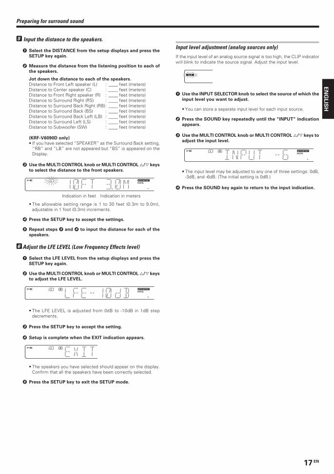
5 Input the distance to the speakers.
1 Select the DISTANCE from the setup displays and press the
SETUP key again.
2 Measure the distance from the listening position to each of
the speakers.
Jot down the distance to each of the speakers.
Distance to Front Left speaker (L) : ____ feet (meters)Distance to Center speaker (C) : ____ feet (meters)Distance to Front Right speaker (R) : ____ feet (meters)Distance to Surround Right (RS) : ____ feet (meters)Distance to Surround Back Right (RB): ____ feet (meters)Distance to Surround Back (BS) : ____ feet (meters)Distance to Surround Back Left (LB) : ____ feet (meters)Distance to Surround Left (LS) : ____ feet (meters)Distance to Subwoofer (SW) : ____ feet (meters)
(KRF-V6090D only)
• If you have selected “SPEAKER” as the Surround Back setting,“RB” and “LB” are not appeared but “BS” is appeared on theDisplay.
3 Use the MULTI CONTROL knob or MULTI CONTROL %/fi keys
to select the distance to the front speakers.
Indication in feet Indication in meters
• The allowable setting range is 1 to 30 feet (0.3m to 9.0m),adjustable in 1 foot (0.3m) increments.
4 Press the SETUP key to accept the settings.
5 Repeat steps 3 and 4 to input the distance for each of the
speakers.
6Adjust the LFE LEVEL (Low Frequency Effects level)
1 Select the LFE LEVEL from the setup displays and press the
SETUP key again.
2 Use the MULTI CONTROL knob or MULTI CONTROL %/fi keys
to adjust the LFE LEVEL.
• The LFE LEVEL is adjusted from 0dB to -10dB in 1dB stepdecrements.
3 Press the SETUP key to accept the setting.
4 Setup is complete when the EXIT indication appears.
• The speakers you have selected should appear on the display.Confirm that all the speakers have been correctly selected.
5 Press the SETUP key to exit the SETUP mode.
Input level adjustment (analog sources only)
If the input level of an analog source signal is too high, the CLIP indicatorwill blink to indicate the source signal. Adjust the input level.
1 Use the INPUT SELECTOR knob to select the source of which the
input level you want to adjust.
• You can store a separate input level for each input source.
2 Press the SOUND key repeatedly until the “INPUT” indication
appears.
3 Use the MULTI CONTROL knob or MULTI CONTROL %/fi keys to
adjust the input level.
• The input level may be adjusted to any one of three settings: 0dB,-3dB, and -6dB. (The initial setting is 0dB.)
4 Press the SOUND key again to return to the input indication.
*5532/15-24/EN 04.11.26, 18:0017
18 EN
EN
GL
ISH
Listening to a source component
Normal playback
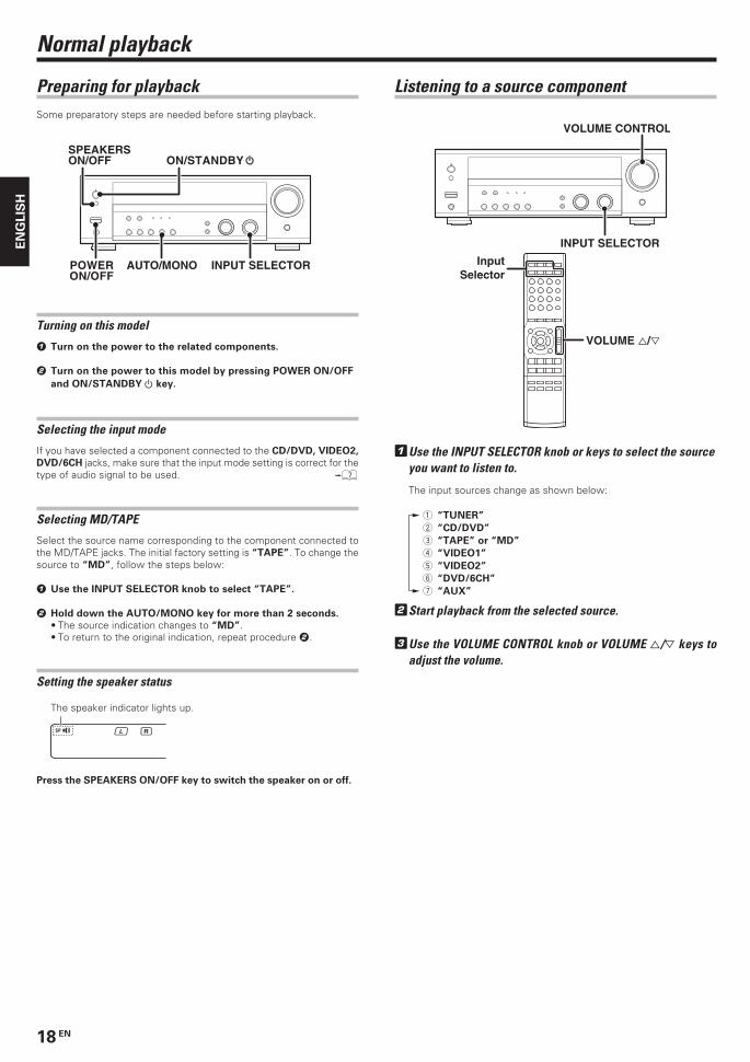
AUTO/MONO INPUT SELECTORPOWERON/OFF
SPEAKERS ON/OFF ON/STANDBY
INPUT SELECTOR
VOLUME CONTROL
InputSelector
VOLUME %/fi
The speaker indicator lights up.
1Use the INPUT SELECTOR knob or keys to select the sourceyou want to listen to.
The input sources change as shown below:
1 “TUNER”
2 “CD/DVD”
3 “TAPE” or “MD”
4 “VIDEO1”
5 “VIDEO2”
6 “DVD/6CH”
7 “AUX”
2Start playback from the selected source.
3Use the VOLUME CONTROL knob or VOLUME %/fi keys toadjust the volume.
Preparing for playbackSome preparatory steps are needed before starting playback.
Turning on this model
1 Turn on the power to the related components.
2 Turn on the power to this model by pressing POWER ON/OFF
and ON/STANDBY key.
Selecting the input mode
If you have selected a component connected to the CD/DVD, VIDEO2,
DVD/6CH jacks, make sure that the input mode setting is correct for thetype of audio signal to be used. 7
Selecting MD/TAPE
Select the source name corresponding to the component connected tothe MD/TAPE jacks. The initial factory setting is “TAPE”. To change thesource to “MD”, follow the steps below:
1 Use the INPUT SELECTOR knob to select “TAPE”.
2 Hold down the AUTO/MONO key for more than 2 seconds.
• The source indication changes to “MD”.• To return to the original indication, repeat procedure 2.
Setting the speaker status
Press the SPEAKERS ON/OFF key to switch the speaker on or off.
*5532/15-24/EN 04.11.23, 13:0418
19 EN
EN
GL
ISH
Normal playback
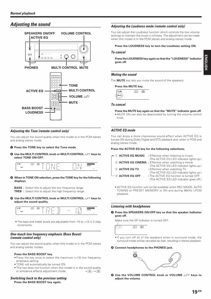
Adjusting the sound
Adjusting the Tone (remote control only)
You can adjust the sound quality when this model is in the PCM stereoand analog stereo mode.
1 Press the TONE key to select the Tone mode.
2 Use the MULTI CONTROL knob or MULTI CONTROL %/fi keys to
select TONE ON/OFF.
3 When in TONE ON selection, press the TONE key for the following
displays.
BASS : Select this to adjust the low frequency range.TREB : Select this to adjust the high frequency range.
4 Use the MULTI CONTROL knob or MULTI CONTROL %/fi keys to
adjust the sound quality.
• The bass and treble levels are adjustable from -10 to +10 in 2 stepincrements.
One-touch low frequency emphasis (Bass Boost)(remote control only)
You can adjust the sound quality when this model is in the PCM stereoand analog stereo modes.
Press the BASS BOOST key.
• Press the key once to select the maximum (+10) low frequencyemphasis setting.
• TONE will automatically be turned ON.• This key does not function when this model is in the sound quality
or ambience effects adjustment mode. ∞~º
Switching back to the previous settingPress the BASS BOOST key again.
ACTIVE EQVOLUME CONTROL
PHONES MULTI CONTROL
SPEAKERS ON/OFF
MUTE
LOUDNESS
TONE
BASS BOOST
ACTIVE EQ
MUTE
VOLUME %/fi
MULTI CONTROL
Adjusting the Loudness mode (remote control only)
You can adjust the Loudness function which controls the low volumesettings to maintain the music’s richness. The adjustment can be madewhen this model is in the PCM stereo and analog stereo mode.
Press the LOUDNESS key to turn the Loudness setting ON.
To cancel
Press the LOUDNESS key again so that the “LOUDNESS” indicator
goes off.
Muting the sound
The MUTE key lets you mute the sound of the speakers.
Press the MUTE key.
To cancel
Press the MUTE key again so that the “MUTE” indicator goes off.
• MUTE ON can also be deactivated by turning the volume controlknob.
ACTIVE EQ mode
You can enjoy a more impressive sound effect when ACTIVE EQ isturned ON during Dolby Digital and DTS playback and, when in PCM andanalog stereo mode.
Press the ACTIVE EQ key for the following selections;
1 ACTIVE EQ MUSIC : Effective when listening to music.(The ACTIVE EQ LED indicator lights up.)
2 ACTIVE EQ CINEMA : Effective when watching a movie.(The ACTIVE EQ LED indicator lights up.)
3 ACTIVE EQ TV : Effective when watching TV.(The ACTIVE EQ LED indicator lights up.)
4 ACTIVE EQ OFF : The ACTIVE EQ function is turned OFF.(The ACTIVE EQ LED indicator goes off.)
• ACTIVE EQ function will not be available when REC MODE, AUTOTUNING or PRESET MEMORY is ON and during 96kHz LPCMplayback.
Listening with headphones
1 Press the SPEAKERS ON/OFF key so that the speaker indicator
goes off.
• If you turn off all of the speakers when in surround mode, thesurround mode will be canceled as well, resulting in stereo playback.
2 Connect headphones to the PHONES jack.
PHONES
3 Use the VOLUME CONTROL knob or VOLUME %/fi keys to
adjust the volume.
Make sure the SP indicator is turned OFF.
*5532/15-24/EN 04.11.23, 13:0419
20 EN
EN
GL
ISH
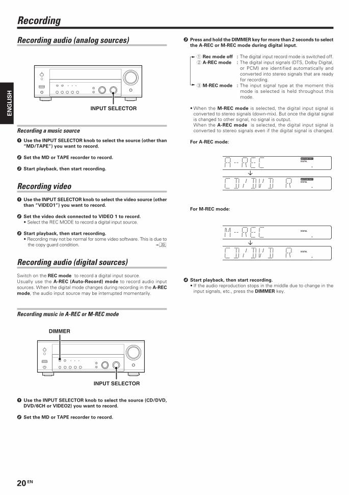
Recording audio (analog sources)
INPUT SELECTOR
Recording
3 Press and hold the DIMMER key for more than 2 seconds to select
the A-REC or M-REC mode during digital input.
1 Rec mode off : The digital input record mode is switched off.2 A-REC mode : The digital input signals (DTS, Dolby Digital,
or PCM) are identified automatically andconverted into stereo signals that are readyfor recording.
3 M-REC mode : The input signal type at the moment thismode is selected is held throughout thismode.
• When the M-REC mode is selected, the digital input signal isconverted to stereo signals (down-mix). But once the digital signalis changed to other signal, no signal is output.When the A-REC mode is selected, the digital input signal isconverted to stereo signals even if the digital signal is changed.
For A-REC mode:
For M-REC mode:
4 Start playback, then start recording.
• If the audio reproduction stops in the middle due to change in theinput signals, etc., press the DIMMER key.
Recording a music source
1 Use the INPUT SELECTOR knob to select the source (other than
“MD/TAPE”) you want to record.
2 Set the MD or TAPE recorder to record.
3 Start playback, then start recording.
Recording video1 Use the INPUT SELECTOR knob to select the video source (other
than “VIDEO1”) you want to record.
2 Set the video deck connected to VIDEO 1 to record.
• Select the REC MODE to record a digital input source.
3 Start playback, then start recording.
• Recording may not be normal for some video software. This is due tothe copy guard condition. ‹
Recording audio (digital sources)Switch on the REC mode to record a digital input source.Usually use the A-REC (Auto-Record) mode to record audio inputsources. When the digital mode changes during recording in the A-REC
mode, the audio input source may be interrupted momentarily.
Recording music in A-REC or M-REC mode
INPUT SELECTOR
DIMMER
1 Use the INPUT SELECTOR knob to select the source (CD/DVD,
DVD/6CH or VIDEO2) you want to record.
2 Set the MD or TAPE recorder to record.
*5532/15-24/EN 04.11.23, 13:0420

21 EN
EN
GL
ISH
Using RDS (Radio Data System)RDS is a system that transmits useful information (in the form of digitaldata) for FM broadcasts along with the broadcast signal. Tuners andreceivers designed for RDS reception can extract the information fromthe broadcast signal for use with various functions, such as automaticdisplay of the station name.
RDS functions:PTY (Program TYpe Identification) Search ¢Automatically tunes to a station that is currently broadcasting thespecified program type (genre).
PS (Program Service Name) Display
Automatically displays the station name transmitted by the RDSstation.
RDS AUTO MEMORY function ¢Automatically selects and stores up to 40 RDS stations in the presetmemory.If fewer than 40 RDS stations have been stored in the preset memory,regular FM stations will be stored in the remaining places.
Radio Text function
Displays the radio text data transmitted by some RDS stations whenyou press the RDS DISP. (Display) key. There is “NO RT” display if notext data is transmitted.
The “RDS” indicator lights up when an RDS broadcast (signal) isreceived.
NoteSome functions and function names may differ for certain countriesand areas.
Before using a function utilizing the RDS, be sure to perform the RDSAuto Memory operation by referring to the description in “PresettingRDS stations (RDS AUTO MEMORY)”. ¢
1Use the INPUT SELECTOR knob or TUNER key to select thetuner.
2Use the BAND key to select the desired broadcast band.
Each press switches the band
as follows:
1 FM
2 AM
3Use the AUTO/MONO key to select the desired tuning method.
Each press switches the tuning method as follows:
1 AUTO lit (auto tuning)2 AUTO not lit (manual tuning)
• Normally, set to “AUTO” (auto tuning). If the radio waves are weakand there is a lot of interference, switch to manual tuning. (Withmanual tuning, stereo broadcasts will be received in monaural.)
4Use the MULTI CONTROL knob or MULTI CONTROL %/ fi keys,or TUNING 1 / ¡ keys to select the station.
Auto tuning : The next station is tuned automatically.Manual tuning : Turn the knob (press the key) to select the desired
station.
Listening to radio broadcasts
This model can store up to 40 stations in the memory and recall them byone-touch operation.Radio stations can be classified into RDS (Radio Data System) stationsand other stations. To listen to or store RDS stations in the presetmemory see “Using RDS (Radio Data System)”.
Tuning (non-RDS) radio stations
“AM” or “FM” indicatorappears in the display
“AUTO” indicator lights up in the display.
Frequency display
“TUNED” is displayedwhen a station is received.
“ST.” lights when a broadcastis being received in stereo.
MULTI CONTROL
INPUT SELECTORBAND AUTO/MONO
TUNER
AUTO/MONOBAND
TUNING
MULTI CONTROL
*5532/15-24/EN 04.11.23, 13:0421
22 EN
EN
GL
ISH
Listening to radio broadcasts
Proceed to step 3 within 20 seconds.
(If more than 20 seconds elapse, press the MEMORY key again).
Blinks for 20 seconds
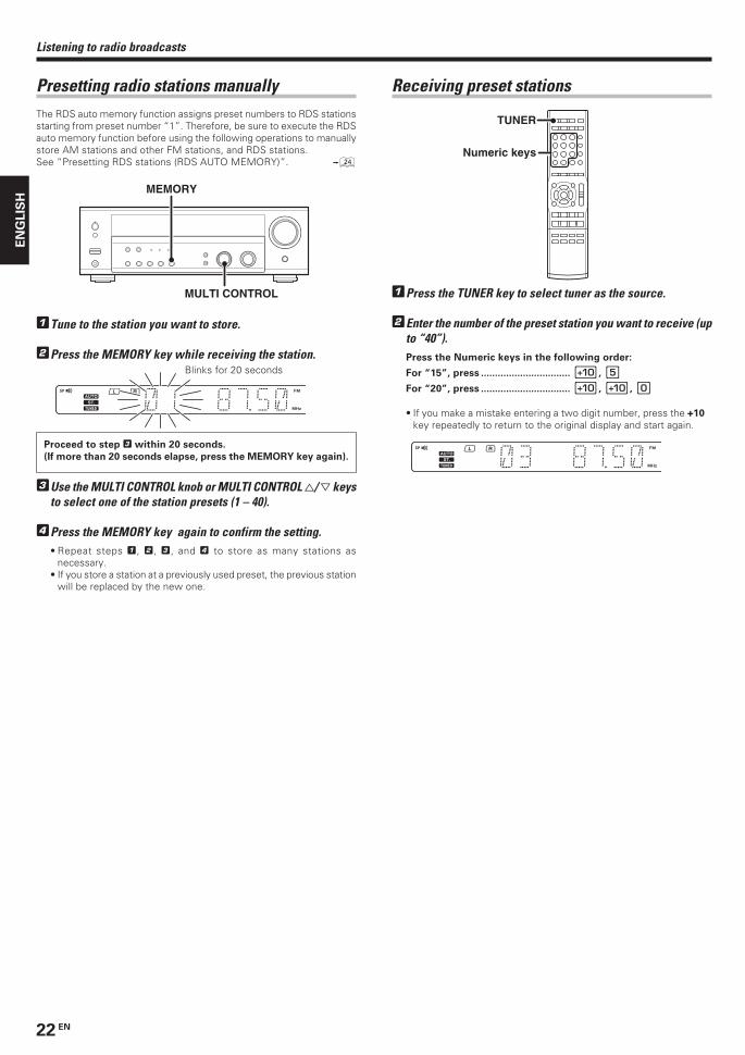
Presetting radio stations manuallyThe RDS auto memory function assigns preset numbers to RDS stationsstarting from preset number “1”. Therefore, be sure to execute the RDSauto memory function before using the following operations to manuallystore AM stations and other FM stations, and RDS stations.See “Presetting RDS stations (RDS AUTO MEMORY)”. ¢
MULTI CONTROL
MEMORY
1Tune to the station you want to store.
2Press the MEMORY key while receiving the station.
3Use the MULTI CONTROL knob or MULTI CONTROL %/ fi keysto select one of the station presets (1 – 40).
4Press the MEMORY key again to confirm the setting.• Repeat steps 1, 2, 3, and 4 to store as many stations as
necessary.• If you store a station at a previously used preset, the previous station
will be replaced by the new one.
Receiving preset stations
TUNER
Numeric keys
1Press the TUNER key to select tuner as the source.
2Enter the number of the preset station you want to receive (upto “40”).Press the Numeric keys in the following order:
For “15”, press ................................ 0, 5
For “20”, press ................................ 0, 0, )
• If you make a mistake entering a two digit number, press the +10
key repeatedly to return to the original display and start again.
*5532/15-24/EN 04.11.23, 13:0422
23 EN
EN
GL
ISH
Using the RDS DISP. (Display) key
RDS DISP.
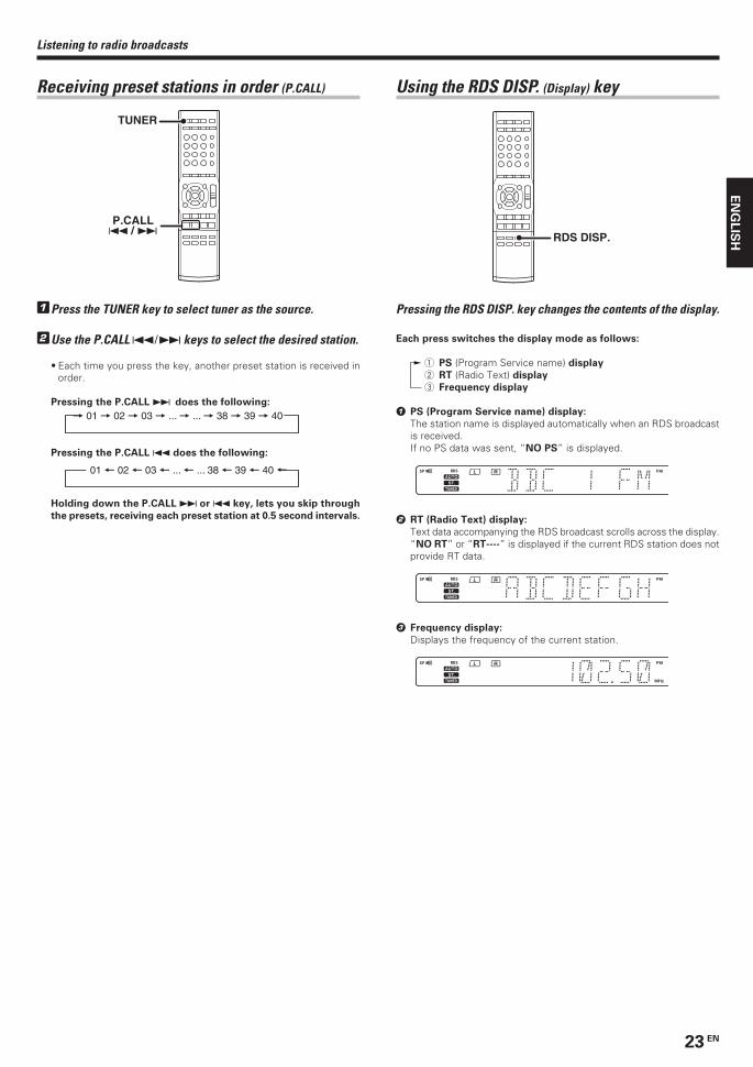
Pressing the RDS DISP. key changes the contents of the display.
Each press switches the display mode as follows:
1 PS (Program Service name) display
2 RT (Radio Text) display
3 Frequency display
1 PS (Program Service name) display:
The station name is displayed automatically when an RDS broadcastis received.If no PS data was sent, “NO PS” is displayed.
2 RT (Radio Text) display:
Text data accompanying the RDS broadcast scrolls across the display.“NO RT” or “RT----” is displayed if the current RDS station does notprovide RT data.
3 Frequency display:
Displays the frequency of the current station.
Listening to radio broadcasts
Receiving preset stations in order (P.CALL)
TUNER
P.CALL 4 / ¢
1Press the TUNER key to select tuner as the source.
2Use the P.CALL 4¥¢ keys to select the desired station.
• Each time you press the key, another preset station is received inorder.
Pressing the P.CALL ¢ does the following:
Pressing the P.CALL 4 does the following:
Holding down the P.CALL ¢ or 4 key, lets you skip through
the presets, receiving each preset station at 0.5 second intervals.
*5532/15-24/EN 04.11.23, 13:0423

24 EN
EN
GL
ISH
Listening to radio broadcasts
Presetting RDS stations (RDS AUTO MEMORY)
This function automatically stores up to 40 RDS stations in the presetmemory. In order to use the PTY function, the RDS stations must bestored in the preset memory using the RDS AUTO MEMORY function.
INPUT SELECTORBAND
MEMORY
1Use the INPUT SELECTOR knob to select the tuner.
2Use the BAND key to set the broadcast band to “FM”.
3Press and hold the MEMORY key for more than 2 seconds.
• After a few minutes, up to 40 RDS stations are preset in order fromchannel “01”.
• Stations already stored in the preset memory may be replaced byRDS stations. (i.e., If the RDS AUTO MEMORY function detects 15RDS stations, the stations currently preset at numbers 01~15 willbe replaced by the RDS stations.)
Under certain receiving conditions, it may take more than 1
minute to complete the search.
“NO PROG” is displayed if this operation is attempted before
performing the RDS Auto Memory operation.
Tuning by Program TYpe (PTY search)
This function lets you set the tuner to automatically search for stationswhich are currently broadcasting the type of program (genre) you wantto listen to.
PTYTUNING
MULTI CONTROL
Preparations
• Execute the RDS auto memory procedure.• Set the broadcast band to FM.• Tune to an RDS station.
Program type table
Program Type Name Display
Pop Music POP MRock Music ROCK MEasy Music EASY MLight Classical Music LIGHT MSerious Classical Music CLASSICSOther Music OTHER MNews NEWSCurrent Affairs AFFAIRSInformation INFOSport SPORTEducation EDUCATEDrama DRAMACulture CULTUREScience SCIENCEVaried Speech VARIED
Program Type Name Display
Weather WEATHERFinance FINANCEChildren’s Program CHILDRENSocial Affairs SOCIALReligion RELIGIONPhone In PHONE INTravel TRAVELLeisure LEISUREJazz Music JAZZCountry Music COUNTRYNational Music NATION MOldies Music OLDIESFolk Music FOLK MDocumentary DOCUMENT
1Press the PTY key to activate the PTY search mode.
When an RDS broadcast is received, the program type is shown onthe display. If no PTY data is available, or if the station is not an RDSstation, “NONE” is displayed.
2While the “PTY” indicator is lit, use the MULTI CONTROLknob or MULTI CONTROL %/ fi keys, or TUNING 1 / ¡keys to select the program type of your choice.
Goes out
3Press the PTY key to start searching.
EXAMPLE: Searching for a Rock Music broadcast.
Display while searching.
Blinks Program type name display
Display when a station is received.
Station name display
• No sound is heard while “PTY” is blinking.• If the desired program type cannot be found, “NO PROG” is
displayed, then after several seconds the display returns to theoriginal display.
To select another program typeRepeat steps 1, 2 and 3.
*5532/15-24/EN 04.11.23, 13:0424
25 EN
EN
GL
ISH
Ambience effects
Manufactured under license from Dolby Laboratories. “Dolby”, “ProLogic”, “Surround EX” and the double-D symbol are trademarks ofDolby Laboratories.
RSLS
CL RSW
TV / SCREEN
No Surround Back speaker With Surround Back speaker
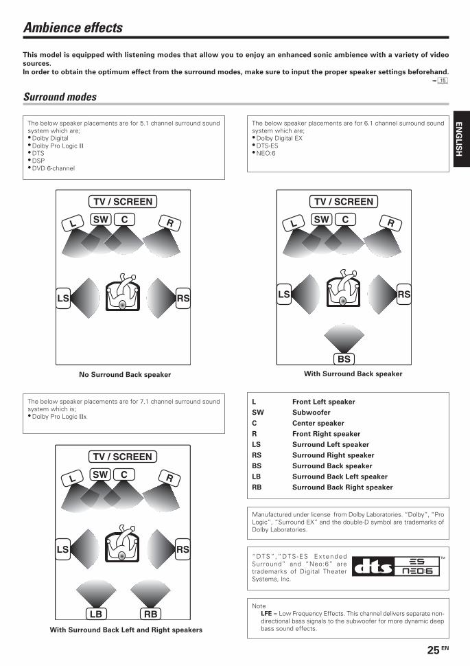
L Front Left speaker
SW Subwoofer
C Center speaker
R Front Right speaker
LS Surround Left speaker
RS Surround Right speaker
BS Surround Back speaker
LB Surround Back Left speaker
RB Surround Back Right speaker
The below speaker placements are for 5.1 channel surround soundsystem which are;• Dolby Digital• Dolby Pro Logic II• DTS• DSP• DVD 6-channel
The below speaker placements are for 6.1 channel surround soundsystem which are;• Dolby Digital EX• DTS-ES• NEO:6
BS
RSLS
CL RSW
TV / SCREEN
NoteLFE = Low Frequency Effects. This channel delivers separate non-directional bass signals to the subwoofer for more dynamic deepbass sound effects.
The below speaker placements are for 7.1 channel surround soundsystem which is;• Dolby Pro Logic IIx
RBLB
RSLS
CL RSW
TV / SCREEN
With Surround Back Left and Right speakers
This model is equipped with listening modes that allow you to enjoy an enhanced sonic ambience with a variety of video
sources.
In order to obtain the optimum effect from the surround modes, make sure to input the proper speaker settings beforehand.
%
Surround modes
“DTS” ,”DTS -ES Ex tendedSurround” and “Neo:6” aretrademarks of Digital TheaterSystems, Inc.
*5532/25-32/EN 04.11.25, 20:2325
26 EN
EN
GL
ISH
Dolby DigitalThe Dolby Digital surround format lets you enjoy up to 5.1 channelsof digital surround sound from Dolby Digital program sources (such
as Laserdisc or DVD software marked ). Compared withprevious Dolby surround, Dolby Digital provides even better soundquality, greater spatial accuracy, and improved dynamic range.
Although a full set of speakers (front left, right, and center, surroundleft and right, and a subwoofer) is required for true 5.1 channel DolbyDigital surround sound, this model lets you enjoy Dolby Digital (andDolby Surround) program sources, even if you connect only the frontspeakers.
Dolby Digital EXDolby Digital EX is an extension of Dolby Digital technology, DolbyDigital EX creates six full-bandwidth output channels from 6.1-channel sources. This is done using a matrix decoder that derivesthree surround channels from the two in the original recording.This is achieved by using three different surround signals, surroundleft, surround right, and surround back, each driving its own array ofspeakers. Think of it as adding a center channel for the rear speakers,which give more diffuse and natural surround effect, even if youwanted the ability to completely encircle the audience with sound,positioning sound effects exactly where they would be heard in reallife. For best results, Dolby Digital EX should be used with moviesoundtracks recorded with Dolby Digital Surround EX which containa digital flag that will automatically activate this feature. However, fortitles released prior to late 2001, this feature has to be activatedmanually.
Although a full set of speakers (front left, right, and center, surroundleft and right, surround back and a subwoofer) is required for true 6.1channel Dolby Digital Surround EX sound, this model lets you enjoyDolby Digital (and Dolby Surround) program sources, even if youconnect only the front speakers.
Although only Dolby Digital soundtracks incorporate a separate lowfrequency channel, connecting a subwoofer will also improve deepbass performance in the other surround modes.
Dolby Digital has a “.1” or LFE channel.The indication “LFE” appears in the display when a signal is beinginput for this channel. ∞
Dolby PRO LOGIC IIx and Dolby PRO LOGIC IIDolby Pro Logic II was designed specifically to provide a new senseof spatiality, directionality and articulation of sounds from DolbySurround encoded sources (such as video and Laserdisc softwaremarked ). This is achieved with an intelligent, built-infeedback logic design, a matrix surround decoding and the decodingof stereo, full bandwidth surround outputs.DOLBY PRO LOGIC IIx enhanced DOLBY PRO LOGIC II’s features.It creates 6.1 channel and 7.1 channel surround sound from stereo or5.1 channel signals. This feature provides you an astonishing ambienceeffect which makes you feel you are surrounded by natural sound.Especially 7.1 channel surround sound can produce real back soundfrom Surround Back speakers.
The PRO LOGIC IIx modes programmed into this model are “MOVIE”,“MUSIC” and “GAME”. The PRO LOGIC II modes programmed intothis model are “MOVIE”, “MUSIC”, “GAME” and “PRO LOGIC”.The “MOVIE” mode has preset characteristics to produce a calibrated,high-level surround sound playback while the “MUSIC” mode hasuser-adjustable characteristics to offer the three optional controls,like “Dimension”, “Center Width” and “Panorama” modes to allowoptimization of the soundfields as desired. The “Dimension” controlallows the user to gradually adjust the soundfield either towards thefront or towards the rear; the “Center Width” control allows variousadjustment of the left-center-right speakers’ balance; the “Panorama”mode extends the front stereo image to include the surround speakersfor an exciting “wraparound” effect with side wall imaging.The “GAME” mode provides surrounded and exciting sound whenyou enjoy game or TV. Especially in PRO LOGIC IIx “GAME” mode,base sound not only from Front and Center but also from Surroundchannel is added to Subwoofer. This provides even more dynamicsurround effects.
Ambience effects
DVD 6-channel modeUsing a DVD player or the like equipped with six (5.1) output channelsand this model, you can enjoy multi-channel encoded DVD sourcematerial in all its splendor. Since the source signals are digital andeach channel is input independently, the resulting sound quality,sense of spaciousness, and dynamic range are superb.
The indication “6CH INPUT” appears in the display during DVD 6-channel mode selection.
DSP modeThe DSP mode lets you add the atmosphere of a live concert or hallto almost any type of program source. These modes are particularlyeffective when used with stereo program sources, like CD, television,and FM radio. You might enjoy trying the ARENA, JAZZ CLUB,THEATER, STADIUM or DISCO mode the next time you watch aconcert or sporting event!
What's DSP?DSP stands for Digital Signal Processor.The way a sound is heard in an actual environment depends on avariety of different factors. One of the most important is reverberation(the act of decaying elements of sound echoing in various places).The DSP modes produce the feeling of presence by using the DSP tocreate reverberation, without spoiling the sound quality of the originalsignal.
DTSThe DTS multi-channel audio format is available on CD, LD and DVDsoftware. DTS is a strictly digital format and cannot be decodedinside most CD, LD or DVD players. For this reason, if you attemptto listen to DTS encoded software through the analog output of yournew CD, LD or DVD player, you will experience digital noise in mostcases. This noise can be quite loud if the analog output is connecteddirectly to a high power amplification system. Proper measures forplaying the digital output as described below should be taken toavoid this situation. To enjoy DTS Digital Surround playback, anexternal 5.1 channel DTS Digital Surround decoder system or anamplifier with a built-in DTS Digital Surround decoder must beconnected to the digital output (S/P DIF, AES/EBU or TosLink) of aCD, LD or DVD player.All models are incorporated with the DTS decoder.
DTS has a “.1” or LFE channel.The indication “LFE” appears in the display when a signal is beinginput for this channel. ∞
DTS-ESDTS-ES (Digital Theater System-Extended Surround) presents 6.1channels surround system with additional Surround Back channelwhich evolved from the conventional 5.1 channels surround system.DTS-ES format that was recorded in DVD, CD or LD comprises of twomodes. DTS-ES Discrete 6.1 produces the discrete surround backwhich is completely independent and DTS-ES Matrix 6.1 producesthe surround back which synthesised within the left and right surroundchannels using matrix technology. DTS-ES has perfect compatibilitywith the conventional 5.1 channels surround system. 6.1 channelssurround with an additional surround back presents a more naturalpresence and surround effects by increasing the impression of thesound image from back. Programs which are recorded using DTS-EStechnology consist of information flags which will be able to controlthe Discrete and Matrix mode. Thus, it can automatically select thebest matched mode.
Neo:6Neo:6 is a new technology which was developed by DTS. It canproduce high grade 6 channels surround with an astonishing fidelityfrom 2 channels content. Neo:6 has 2 modes, “CINEMA” mode is formovic playback and “MUSIC” mode is for music playback.
DTS has a “.1” or LFE channel.The indication “LFE” appears in the display when a signal is beinginput for this channel. ∞
*5532/25-32/EN 04.11.25, 20:2326

27 EN
EN
GL
ISH
Ambience effects
Continued to next page
When the DOLBY DIGITAL or DOLBY DIGITAL EX signal is input:(The DOLBY DIGITAL or PRO LOGIC indicator lights up.)
1 DOLBY DIGITAL : DOLBY DIGITAL surround.2 DOLBY DIGITAL EX : DOLBY DIGITAL EX surround.
(The DOLBY DIGITAL EX indicator lightsup.)
3 PL IIx MOVIE : PRO LOGIC IIx surround MOVIE mode.(The PRO LOGIC indicator lights up.)
4 PL IIx MUSIC : PRO LOGIC IIx surround MUSIC mode.(The PRO LOGIC indicator lights up.)
5 PL IIx GAME : PRO LOGIC IIx surround GAME mode.(The PRO LOGIC indicator lights up.)
6 PL II MOVIE : PRO LOGIC II surround MOVIE mode.(The PRO LOGIC indicator lights up.)
7 PL II MUSIC : PRO LOGIC II surround MUSIC mode.(The PRO LOGIC indicator lights up.)
8 PL II GAME : PRO LOGIC II surround GAME mode.(The PRO LOGIC indicator lights up.)
9 PRO LOGIC : PRO LOGIC II surround PRO LOGIC mode.(The PRO LOGIC indicator lights up.)
0 STEREO : Normal stereo playback.
When you select DOLBY DIGITAL
“DOLBY DIGITAL” will scroll from right to left.
When the DTS or DTS-ES (matrix, discrete or bitstream) signal isinput:(The DTS LED indicator lights up.)
1 DTS-ES MATRIX 6.1 : DTS - ES MATRIX 6.1 channel surround(The DTS-ES and MATRIX 6.1 indicatorslight up.)
2 DTS-ES DISCRETE 6.1 : DTS - ES DISCRETE 6.1channel surround(The DTS-ES and DISCRETE 6.1 indicatorslight up.)
3 DTS : DTS 5.1 channel surround(The DTS indicator lights up.)
4 DTS + NEO:6 CINEMA : DTS + NEO:6 surround CINEMA mode.(The DTS and NEO:6 indicators light up.)
5 STEREO : Normal stereo playback
When the analog signal or the digital signal (except for DOLBYDIGITAL or DTS signal) is input:1 PL IIx MOVIE : PRO LOGIC IIx surround MOVIE mode.
(The PRO LOGIC indicator lights up.)2 PL IIx MUSIC : PRO LOGIC IIx surround MUSIC mode.
(The PRO LOGIC indicator lights up.)3 PL IIx GAME : PRO LOGIC IIx surround GAME mode.
(The PRO LOGIC indicator lights up.)4 PL II MOVIE : PRO LOGIC II surround MOVIE mode.
(The PRO LOGIC indicator lights up.)5 PL II MUSIC : PRO LOGIC II surround MUSIC mode.
(The PRO LOGIC indicator lights up.)6 PL II GAME : PRO LOGIC II surround GAME mode.
(The PRO LOGIC indicator lights up.)7 PRO LOGIC : PRO LOGIC II surround PRO LOGIC mode.
(The PRO LOGIC indicator lights up.)8 NEO:6 CINEMA : NEO:6 surround CINEMA mode.
(The NEO:6 indicator lights up.)9 NEO:6 MUSIC : NEO:6 surround MUSIC mode.
(The NEO:6 indicator lights up.)0 ARENA : DSP Surround ARENA mode.
Surround playThe DTS compatible models can reproduce a CD, DVD, or LD carrying theDTS mark.DOLBY DIGITAL can be used when playing DVD or LD software bearingthe mark and DOLBY DIGITAL format digital broadcasts (etc.).DOLBY PRO LOGIC can be used when playing video, DVD, or LDsoftware bearing the mark.
INPUT SELECTORINPUT MODE
LISTEN MODE
InputSelector
LISTEN MODE
Preparations
• Turn ON related components.• Complete “Preparing for surround sound” (speaker settings).%• Use the INPUT SELECTOR knob or Input Selector keys to select
the component you wish to play back with surround sound.• Use the INPUT MODE key to select the input mode (analog or
digital) for the source you wish to playback. 7• Noise will be produced when a DTS source is played by selecting the
analog input.
1Start playing the video software.
2Press the LISTEN MODE key to select the listening mode.
The listening mode settings are stored separately for each input. If theinput mode is set to full auto (“AUTO DETECT” lights), this modelselects the optimal listening mode automatically based on the type ofinput signal and the speaker settings.
Each press of the LISTEN MODE key switches the setting as
listed.
The listening mode settings are different depending on the type
of input signal.
Dolby Digital Surround EX compliant disc :
Dolby Digital Surround EX compliant disc contains identificationsignals. When you choose FULL AUTO during “Input mode settings”(7), this amplifier detects the identification signals and change theListen mode to the DOLBY DIGITAL EX (Dolby Digital Surround EXmode) automatically.But sometimes we find some discs which are Dolby Digital SurroundEX compliant disc but it does not contain the identification signals. Ifyou find the notice like “Surround EX” on the label of disc or package,you can choose DOLBY DIGITAL EX, then you can enjoy DolbyDigital Surround EX sound.
*5532/25-32/EN 04.11.25, 20:2327
28 EN
EN
GL
ISH
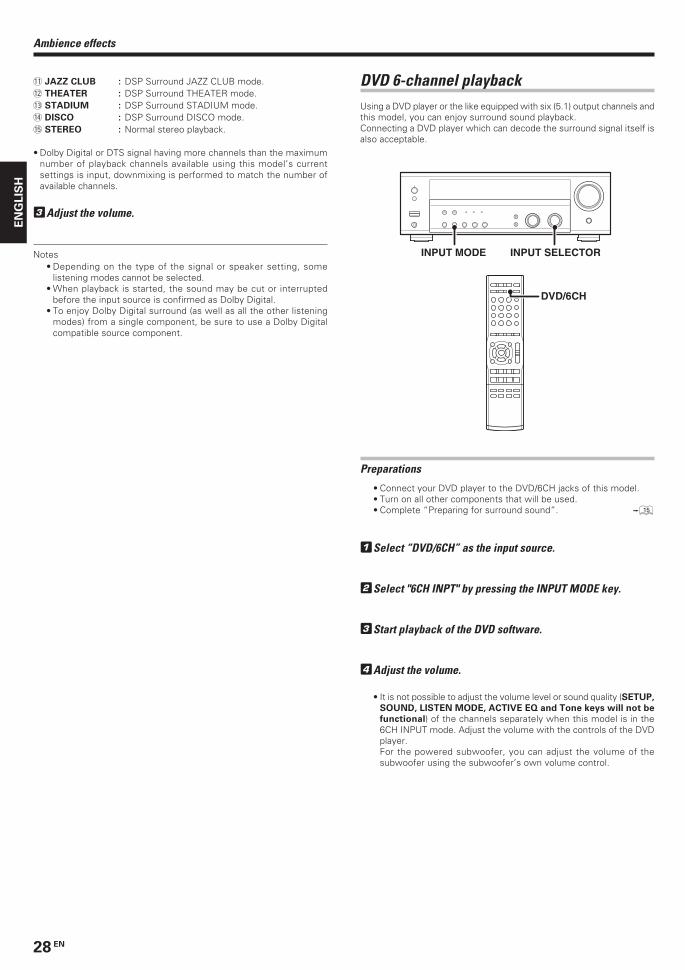
DVD 6-channel playbackUsing a DVD player or the like equipped with six (5.1) output channels andthis model, you can enjoy surround sound playback.Connecting a DVD player which can decode the surround signal itself isalso acceptable.
DVD/6CH
INPUT SELECTORINPUT MODE
Preparations
• Connect your DVD player to the DVD/6CH jacks of this model.• Turn on all other components that will be used.• Complete “Preparing for surround sound”. %
1Select “DVD/6CH” as the input source.
2Select "6CH INPT" by pressing the INPUT MODE key.
3Start playback of the DVD software.
4Adjust the volume.
• It is not possible to adjust the volume level or sound quality (SETUP,
SOUND, LISTEN MODE, ACTIVE EQ and Tone keys will not be
functional) of the channels separately when this model is in the6CH INPUT mode. Adjust the volume with the controls of the DVDplayer.For the powered subwoofer, you can adjust the volume of thesubwoofer using the subwoofer’s own volume control.
Ambience effects
- JAZZ CLUB : DSP Surround JAZZ CLUB mode.= THEATER : DSP Surround THEATER mode.~ STADIUM : DSP Surround STADIUM mode.! DISCO : DSP Surround DISCO mode.@ STEREO : Normal stereo playback.
• Dolby Digital or DTS signal having more channels than the maximumnumber of playback channels available using this model’s currentsettings is input, downmixing is performed to match the number ofavailable channels.
3Adjust the volume.
Notes• Depending on the type of the signal or speaker setting, some
listening modes cannot be selected.• When playback is started, the sound may be cut or interrupted
before the input source is confirmed as Dolby Digital.• To enjoy Dolby Digital surround (as well as all the other listening
modes) from a single component, be sure to use a Dolby Digitalcompatible source component.
*5532/25-32/EN 04.11.25, 20:2328
29 EN
EN
GL
ISH
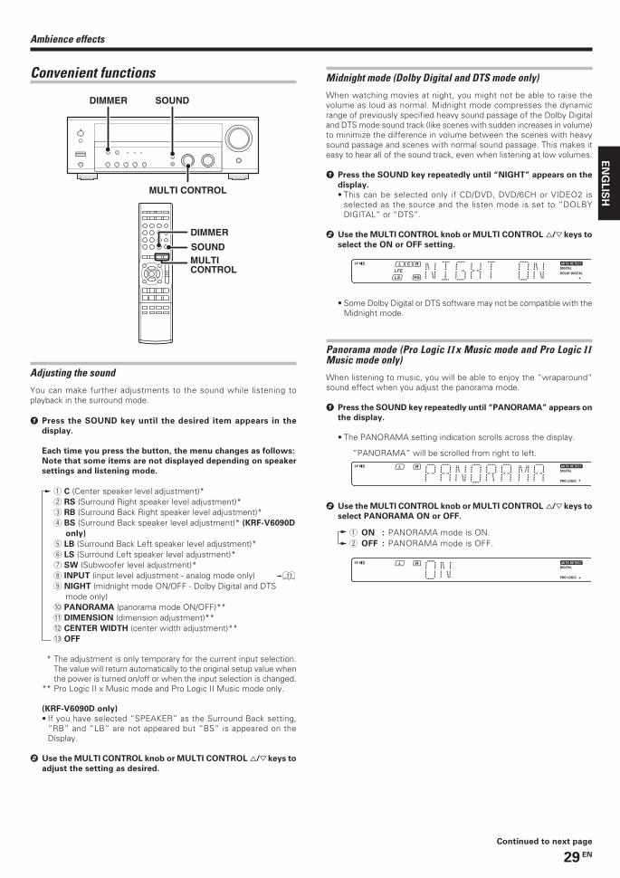
Convenient functions
MULTI CONTROL
DIMMER SOUND
SOUND
DIMMER
MULTI CONTROL
Ambience effects
Midnight mode (Dolby Digital and DTS mode only)
When watching movies at night, you might not be able to raise thevolume as loud as normal. Midnight mode compresses the dynamicrange of previously specified heavy sound passage of the Dolby Digitaland DTS mode sound track (like scenes with sudden increases in volume)to minimize the difference in volume between the scenes with heavysound passage and scenes with normal sound passage. This makes iteasy to hear all of the sound track, even when listening at low volumes.
1 Press the SOUND key repeatedly until “NIGHT” appears on the
display.
• This can be selected only if CD/DVD, DVD/6CH or VIDEO2 isselected as the source and the listen mode is set to “DOLBYDIGITAL” or “DTS”.
2 Use the MULTI CONTROL knob or MULTI CONTROL %/fi keys to
select the ON or OFF setting.
• Some Dolby Digital or DTS software may not be compatible with theMidnight mode.
Panorama mode (Pro Logic IIx Music mode and Pro Logic IIMusic mode only)
When listening to music, you will be able to enjoy the “wraparound”sound effect when you adjust the panorama mode.
1 Press the SOUND key repeatedly until “PANORAMA” appears on
the display.
• The PANORAMA setting indication scrolls across the display.
“PANORAMA” will be scrolled from right to left.
2 Use the MULTI CONTROL knob or MULTI CONTROL %/fi keys to
select PANORAMA ON or OFF.
1 ON : PANORAMA mode is ON.2 OFF : PANORAMA mode is OFF.
Continued to next page
Adjusting the sound
You can make further adjustments to the sound while listening toplayback in the surround mode.
1 Press the SOUND key until the desired item appears in the
display.
Each time you press the button, the menu changes as follows:
Note that some items are not displayed depending on speaker
settings and listening mode.
1 C (Center speaker level adjustment)*2 RS (Surround Right speaker level adjustment)*3 RB (Surround Back Right speaker level adjustment)*4 BS (Surround Back speaker level adjustment)* (KRF-V6090D
only)
5 LB (Surround Back Left speaker level adjustment)*6 LS (Surround Left speaker level adjustment)*7 SW (Subwoofer level adjustment)*8 INPUT (input level adjustment - analog mode only) &
9 NIGHT (midnight mode ON/OFF - Dolby Digital and DTSmode only)
0 PANORAMA (panorama mode ON/OFF)**- DIMENSION (dimension adjustment)**= CENTER WIDTH (center width adjustment)**~ OFF
* The adjustment is only temporary for the current input selection.The value will return automatically to the original setup value whenthe power is turned on/off or when the input selection is changed.
** Pro Logic II x Music mode and Pro Logic II Music mode only.
(KRF-V6090D only)
• If you have selected “SPEAKER” as the Surround Back setting,“RB” and “LB” are not appeared but “BS” is appeared on theDisplay.
2 Use the MULTI CONTROL knob or MULTI CONTROL %/fi keys to
adjust the setting as desired.
*5532/25-32/EN 04.11.25, 20:2429

30 EN
EN
GL
ISH
Ambience effects
Dimension mode (Pro Logic IIx Music mode and Pro Logic IIMusic mode only)
When listening to music with certain recordings, you will also be able toachieve a suitable balance from all the speakers by adjusting thedimension mode.
1 Press the SOUND key repeatedly until “DIMENSION” appears on
the display.
• The DIMENSION indication scrolls across the display.
2 Use the MULTI CONTROL knob or MULTI CONTROL %/fi keys to
adjust the soundfield towards the rear or the front.
Soundfield is adjusted towards the front.
Soundfield is in neutral position.
Soundfield is adjusted towards the rear.
Center Width mode (Pro Logic IIx Music mode and Pro Logic IIMusic mode only)
Center Width adjustment allows you to enjoy an enhanced sound whenlistening to music through center image from only center speaker, or leftand right speakers or various combinations adjustments.
1 Press the SOUND key repeatedly until “CENTER WIDTH” appears
on the display.
• The CENTER WIDTH indication scrolls across the display.• When the center speaker is switched OFF, this mode will not be
effective.
2 Use the MULTI CONTROL knob or MULTI CONTROL %/ fi keys to
adjust the left-center-right output.
Center image will be heard from center speaker only.
Center image will be heard from left and right speakers only.
• When in other positions, center image from center speaker, left andright speakers can be heard simultaneously with variouscombinations.
Display dimmer adjustment
The dimmer function lets you select the brightness of this model'sdisplay. You might find this useful if you darken your room to watchmovies or listen to music.
If you want to use the remote control unit, press the TUNER, MD/
TAPE, VIDEO 1, VIDEO 2 or AUX key on the remote control unit
to set it to the receiver control mode.
Each time you press the DIMMER key, the display brightness
changes among the three available settings. Select the brightness
level you find most pleasing.
96kHz LPCM playback
This model is compatible with the 96kHz LPCM playback. To play a 96kHzDVD, set the listen mode to “STEREO”.
• In F-AUTO input mode, the listen mode will automatically be STEREO.• When in D-MANUAL input mode (listen mode is not STEREO), “FS
96kHz” will appear in the display and no sound can be heard from thespeakers.Press the LISTEN MODE key (the listen mode changes to the STEREOmode) to output sound from the speakers.
5532/25-32/EN 05.2.16, 10:14 AM30
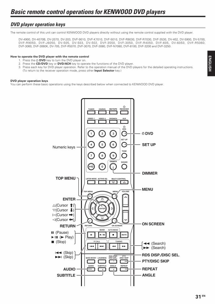
31 EN
EN
GL
ISH
DVD player operation keysThe remote control of this unit can control KENWOOD DVD players directly without using the remote control supplied with the DVD player.
DV-4900, DV-4070B, DV-2070, DV-203, DVF-9010, DVF-K7010, DVF-5010, DVF-R9030, DVF-R7030, DVF-3530, DV-402, DV-5900, DV-5700,DVF-R9050, DVF-J6050, DV-505, DV-503, DV-502, DVF-3550, DVF-3050, DVF-R4050, DVF-605, DV-6050, DVF-R5060,DVF-3060, DVF-3060K, DV-705, DVF-R5070 ,DVF-3070, DVF-3080, DVF-N7080, DVF-8100, DVF-3200 and DVF-3250.
How to operate the DVD player with the remote control
1. Press the DVD key to turn the DVD player on.2. Press the CD/DVD key or DVD/6CH key to operate the functions of the DVD player.3. Press each key for DVD player operation. Refer to the operation manual of the DVD players for the detailed operating instructions.
(To return to the receiver operation mode, press other Input Selector key.)
DVD player operation keys
You can perform these basic operations using the keys described below when connected to KENWOOD DVD player.
Basic remote control operations for KENWOOD DVD players
CD/DVD MD/TAPE RECEIVER
DVD/6CHVIDEO 2VIDEO 1
DVD
SET UP
TONE
SOUNDDIMMER
MULTI CONTROLACTIVE EQLISTEN MODE
TOP MENU
RETURN ON SCREEN
MENU
ENTER
BAND
MUTE
BASS BOOST LOUDNESS DISC SEL. DISC SKIP
REPEATANGLESUBTITLEAUDIO
RDS DISP. PTY
RETURN
AUDIO
MENU
1 (Search)¡ (Search)
Numeric keys
7 (Stop)6 (3 Play)8 (Pause)
ENTER
%(Cursor »)fi(Cursor «)#(Cursor \)@(Cursor |)
DVD
SET UP
DIMMERTOP MENU
ON SCREEN
PTY/DISC SKIP
REPEAT
ANGLE
RDS DISP./DISC SEL.
SUBTITLE
4 (Skip)¢ (Skip)
5532/25-32/EN 05.2.16, 10:14 AM31
32 EN
EN
GL
ISH
*5532/25-32/EN 04.11.25, 20:2432
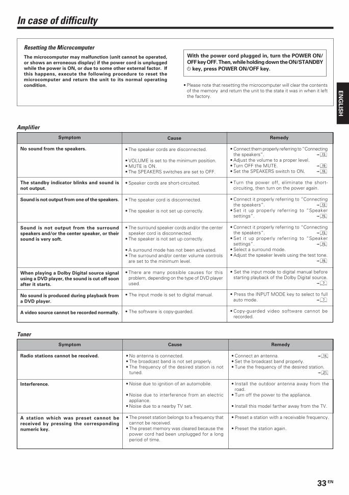
33 EN
EN
GL
ISH
Amplifier
Cause
• The speaker cords are disconnected.
• VOLUME is set to the minimum position.• MUTE is ON.• The SPEAKERS switches are set to OFF.
• Speaker cords are short-circuited.
• The speaker cord is disconnected.
• The speaker is not set up correctly.
• The surround speaker cords and/or the centerspeaker cord is disconnected.
• The speaker is not set up correctly.
• A surround mode has not been activated.• The surround and/or center volume controls
are set to the minimum level.
• There are many possible causes for thisproblem, depending on the type of DVD playerused.
• The input mode is set to digital manual.
• The software is copy-guarded.
Remedy
• Connect them properly referring to “Connectingthe speakers”. #
• Adjust the volume to a proper level.• Turn OFF the MUTE. (• Set the SPEAKERS switch to ON. *
• Turn the power off, eliminate the short-circuiting, then turn on the power again.
• Connect it properly referring to “Connectingthe speakers”. #
• Set it up properly referring to “Speakersettings”. %
• Connect it properly referring to “Connectingthe speakers”. #
• Set it up properly referring to “Speakersettings”. %
• Select a surround mode.• Adjust the speaker levels using the test tone.
^
• Set the input mode to digital manual beforestarting playback of the Dolby Digital source.
7
• Press the INPUT MODE key to select to fullauto mode. 7
• Copy-guarded video software cannot berecorded.
Symptom
No sound from the speakers.
The standby indicator blinks and sound is
not output.
Sound is not output from one of the speakers.
Sound is not output from the surround
speakers and/or the center speaker, or their
sound is very soft.
When playing a Dolby Digital source signal
using a DVD player, the sound is cut off soon
after it starts.
No sound is produced during playback from
a DVD player.
A video source cannot be recorded normally.
In case of difficulty
Resetting the MicrocomputerThe microcomputer may malfunction (unit cannot be operated,
or shows an erroneous display) if the power cord is unplugged
while the power is ON, or due to some other external factor. If
this happens, execute the following procedure to reset the
microcomputer and return the unit to its normal operating
condition.
With the power cord plugged in, turn the POWER ON/
OFF key OFF. Then, while holding down the ON/STANDBY
key, press POWER ON/OFF key.
Tuner
Cause
• No antenna is connected.• The broadcast band is not set properly.• The frequency of the desired station is not
tuned.
• Noise due to ignition of an automobile.
• Noise due to interference from an electricappliance.
• Noise due to a nearby TV set.
• The preset station belongs to a frequency thatcannot be received.
• The preset memory was cleared because thepower cord had been unplugged for a longperiod of time.
Remedy
• Connect an antenna. $• Set the broadcast band properly.• Tune the frequency of the desired station.
¡
• Install the outdoor antenna away from theroad.
• Turn off the power to the appliance.
• Install this model farther away from the TV.
• Preset a station with a receivable frequency.
• Preset the station again.
Symptom
Radio stations cannot be received.
Interference.
A station which was preset cannot be
received by pressing the corresponding
numeric key.
• Please note that resetting the microcomputer will clear the contentsof the memory and return the unit to the state it was in when it leftthe factory.
*5532/33-36/EN 04.11.25, 20:2433
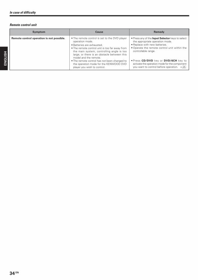
34 EN
EN
GL
ISH
In case of difficulty
Remote control unit
Cause
• The remote control is set to the DVD playeroperation mode.
• Batteries are exhausted.• The remote control unit is too far away from
the main system, controlling angle is toolarge, or there is an obstacle between thismodel and the remote.
• The remote control has not been changed tothe operation mode for the KENWOOD DVDplayer you wish to control.
Remedy
• Press any of the Input Selector keys to selectthe appropriate operation mode.
• Replace with new batteries.• Operate the remote control unit within the
controllable range.
• Press CD/DVD key or DVD/6CH key toactivate the operation mode for the componentyou want to control before operation. ⁄
Symptom
Remote control operation is not possible.
*5532/33-36/EN 04.11.25, 20:2434
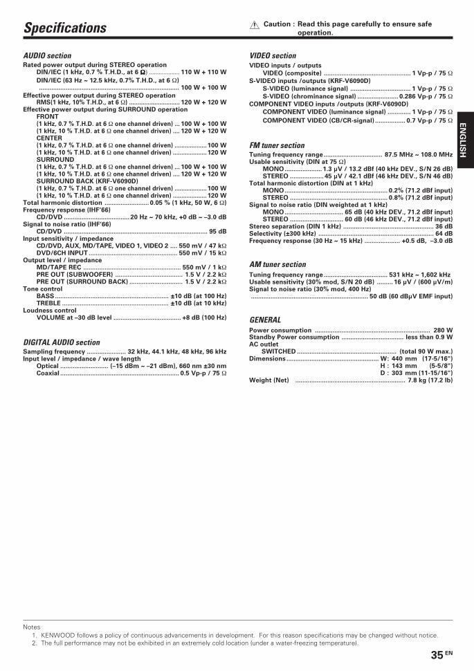
35 EN
EN
GL
ISH
Specifications Caution : Read this page carefully to ensure safe
operation.
AUDIO sectionRated power output during STEREO operation
DIN/IEC (1 kHz, 0.7 % T.H.D., at 6 ΩΩΩΩΩ) ................... 110 W + 110 W
DIN/IEC (63 Hz ~ 12.5 kHz, 0.7% T.H.D., at 6 Ω)............................................................................... 100 W + 100 W
Effective power output during STEREO operationRMS(1 kHz, 10% T.H.D., at 6 Ω) .............................. 120 W + 120 W
Effective power output during SURROUND operationFRONT(1 kHz, 0.7 % T.H.D. at 6 Ω one channel driven) ... 100 W + 100 W(1 kHz, 10 % T.H.D. at 6 Ω one channel driven) .... 120 W + 120 WCENTER(1 kHz, 0.7 % T.H.D. at 6 Ω one channel driven) ...................100 W(1 kHz, 10 % T.H.D. at 6 Ω one channel driven) .................... 120 WSURROUND(1 kHz, 0.7 % T.H.D. at 6 Ω one channel driven) ... 100 W + 100 W(1 kHz, 10 % T.H.D. at 6 Ω one channel driven) .... 120 W + 120 WSURROUND BACK (KRF-V6090D)(1 kHz, 0.7 % T.H.D. at 6 Ω one channel driven) ...................100 W(1 kHz, 10 % T.H.D. at 6 Ω one channel driven) .................... 120 W
Total harmonic distortion ......................... 0.05 % (1 kHz, 50 W, 6 Ω)Frequency response (IHF’66)
CD/DVD ..................................... 20 Hz ~ 70 kHz, +0 dB ~ –3.0 dBSignal to noise ratio (IHF’66)
CD/DVD ................................................................................. 95 dBInput sensitivity / impedance
CD/DVD, AUX, MD/TAPE, VIDEO 1, VIDEO 2 .... 550 mV / 47 kΩDVD/6CH INPUT .................................................. 550 mV / 15 kΩ
Output level / impedanceMD/TAPE REC ....................................................... 550 mV / 1 kΩPRE OUT (SUBWOOFER) ...................................... 1.5 V / 2.2 kΩPRE OUT (SURROUND BACK) .............................. 1.5 V / 2.2 kΩ
Tone controlBASS................................................................ ±10 dB (at 100 Hz)TREBLE ............................................................ ±10 dB (at 10 kHz)
Loudness controlVOLUME at –30 dB level ...................................... +8 dB (100 Hz)
DIGITAL AUDIO sectionSampling frequency ...................... 32 kHz, 44.1 kHz, 48 kHz, 96 kHzInput level / impedance / wave length
Optical ........................... (–15 dBm ~ –21 dBm), 660 nm ±30 nmCoaxial ................................................................... 0.5 Vp-p / 75 Ω
VIDEO sectionVIDEO inputs / outputs
VIDEO (composite) ................................................. 1 Vp-p / 75 ΩS-VIDEO inputs /outputs (KRF-V6090D)
S-VIDEO (luminance signal) .................................. 1 Vp-p / 75 ΩS-VIDEO (chrominance signal) ....................... 0.286 Vp-p / 75 Ω
COMPONENT VIDEO inputs /outputs (KRF-V6090D)
COMPONENT VIDEO (luminance signal) ............. 1 Vp-p / 75 ΩCOMPONENT VIDEO (CB/CR-signal) ................. 0.7 Vp-p / 75 Ω
FM tuner sectionTuning frequency range................................. 87.5 MHz ~ 108.0 MHzUsable sensitivity (DIN at 75 Ω)
MONO..................... 1.3 µV / 13.2 dBf (40 kHz DEV., S/N 26 dB)STEREO ................... 45 µV / 42.1 dBf (46 kHz DEV., S/N 46 dB)
Total harmonic distortion (DIN at 1 kHz)MONO.......................................................... 0.2% (71.2 dBf input)STEREO ....................................................... 0.8% (71.2 dBf input)
Signal to noise ratio (DIN weighted at 1 kHz)MONO................................. 65 dB (40 kHz DEV., 71.2 dBf input)STEREO .............................. 60 dB (46 kHz DEV., 71.2 dBf input)
Stereo separation (DIN 1 kHz) ................................................... 36 dBSelectivity (±300 kHz) ................................................................. 64 dBFrequency response (30 Hz ~ 15 kHz) .................... +0.5 dB, –3.0 dB
AM tuner sectionTuning frequency range.................................... 531 kHz ~ 1,602 kHzUsable sensitivity (30% mod, S/N 20 dB) ......... 16 µV / (600 µV/m)Signal to noise ratio (30% mod, 400 Hz).................................................................. 50 dB (60 dBµV EMF input)
GENERALPower consumption ................................................................. 280 WStandby Power consumption ................................... less than 0.9 WAC outlet
SWITCHED ........................................................ (total 90 W max.)Dimensions .................................................... W: 440 mm (17-5/16")
H : 143 mm (5-5/8")D : 303 mm (11-15/16")
Weight (Net) .............................................................. 7.8 kg (17.2 lb)
Notes1. KENWOOD follows a policy of continuous advancements in development. For this reason specifications may be changed without notice.2. The full performance may not be exhibited in an extremely cold location (under a water-freezing temperature).
*5532/33-36/EN 04.11.25, 20:2435

36 EN
EN
GL
ISH
For your recordsRecord the serial number, found on the back of the unit, in the spacesdesignated on the warranty card, and in the space provided below. Referto the model and serial numbers whenever you call upon your dealer forinformation or service on this product.
Model_____________________ Serial Number_____________________
*5532/33-36/EN 04.11.25, 20:2436