ATTICUS 5 PC FIREPLACE TOOLSET - GHP Group Inc. Manual.pdf · 1 Warming Y our Home . Warming Your...
15
Warming Your H o m e. Warming Your H e a r t. ATTICUS 5 PC FIREPLACE TOOLSET MODEL #FA617TL Questions, problems, missing parts? Before returning to your retailer, call our customer service department at 1-877-447-4768, 8:30 a.m.-4:30 p.m., CST, Monday-Friday or email us at [email protected]. Printed in China 40-10-236 6440 W. Howard St. Niles, IL 60714-3302 877-447-4768 Español p. 6 Français p. 11 1
Transcript of ATTICUS 5 PC FIREPLACE TOOLSET - GHP Group Inc. Manual.pdf · 1 Warming Y our Home . Warming Your...

1
W a r m i n g Y o u r H o m e. W a r m i n g Y o u r H e a r t.
ATTICUS 5 PC FIREPLACE TOOLSET
MODEL #FA617TL
Questions, problems, missing parts? Before returning to your retailer, call our customer service department at 1-877-447-4768, 8:30 a.m.-4:30 p.m., CST, Monday-Friday or email us at
[email protected] in China
40-10-236
6440 W. Howard St.Niles, IL 60714-3302
877-447-4768
Español p. 6
Français p. 11
1

2
PACKAGE CONTENTS
PART DESCRIPTION QUANTITYA Stand Base 1B Stand Frame 1C Tongs 1D Shovel 1E Poker 1F Brush 1G Stand Bracket 1H Stand Top 1
A
B
C
D
G
H
F
E

3
HARDWARE CONTENTS (shown actual size)
TOOLS REQUIRED FOR ASSEMBLY (not included)
PREPARATION
SAFETY INFORMATION
WARNING
Please read and understand this entire manual before attempting to assemble, operate or install the product.
Before beginning assembly of product, make sure all parts are present. Compare parts with package contents list and hardware contents list. If any part is missing or damaged, do not attempt toassemble the product.
Estimated Assembly Time: 10 minutes
• Do not allow children to play with or around toolset.• Do not attempt to clean tools while they are hot.• Hot particles may stick to surface of tools.• TOOL HANDLES AND TOOLS MAY BECOME HOT DURING AND AFTER USE.• USE HEAT-RESISTANT GLOVES TO HANDLE HOT TOOLS.
BoltM6 X 20mm
Qty. 1
Phillips screwdriver.
AA
4
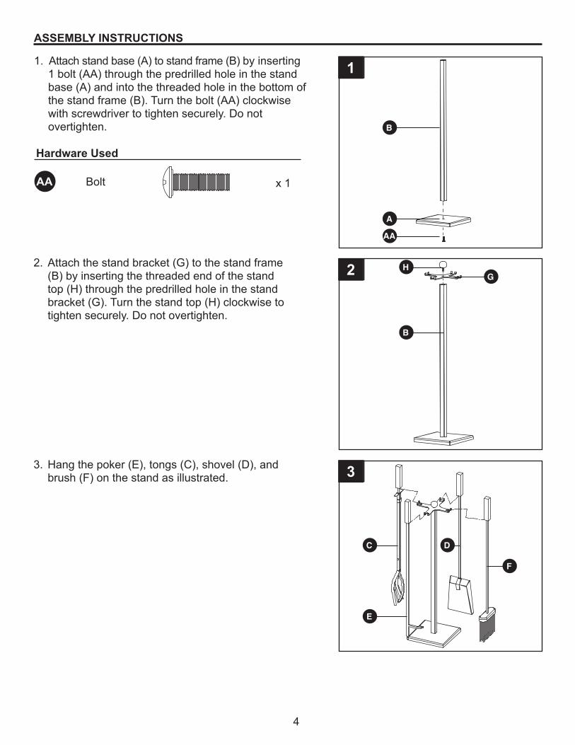
ASSEMBLY INSTRUCTIONS
Hardware Used
1. Attach stand base (A) to stand frame (B) by inserting 1 bolt (AA) through the predrilled hole in the stand base (A) and into the threaded hole in the bottom of the stand frame (B). Turn the bolt (AA) clockwise with screwdriver to tighten securely. Do not overtighten.
2. Attach the stand bracket (G) to the stand frame (B) by inserting the threaded end of the stand top (H) through the predrilled hole in the stand bracket (G). Turn the stand top (H) clockwise to tighten securely. Do not overtighten.
3. Hang the poker (E), tongs (C), shovel (D), and brush (F) on the stand as illustrated.
1
2
3
Bolt x 1AA
AA
A
B
C D
E
B
HG
F

5
CARE AND MAINTENANCE• Use a soft cloth to wipe tools and stand.• Do not attempt to clean tools while they are hot.• Store tools in a cool, clean, dry place.
WARRANTY
If within one year from the date of original purchase, this item fails due to a defect in material or workmanship, we will replace or repair at our option, free of charge. To order parts or to obtain war-ranty service, call 1-877-447-4768, 8:30 a.m.-4:30 p.m., CST, Monday - Friday. This warranty does not cover defects resulting from improper or abnormal use, misuse, accident, or alteration. Failure to follow all instructions in the owner’s manual will also void this warranty. The manufacturer will not be liable for incidental or consequential damages. Some states do not allow the exclusion or limitation of incidental or consequential damages, so the above limitation or exclusion of incidental or consequential damages may not apply to you. This warranty gives you specific legal rights, and you may also have other rights which vary from state to state.
REPLACEMENT PARTS LIST
For replacement parts, call our customer service department at 1-877-447-4768, 8:30 a.m.-4:30 p.m, CST, Monday - Friday.
PART DESCRIPTION PART NO.A Stand Base 40-01-676B Stand Frame 40-01-677C Tongs 40-01-678D Shovel 40-01-679E Poker 40-01-680F Brush 40-01-681G Stand Bracket 40-01-682H Stand Top 40-01-683I Brush Cap 40-01-684J Brush Head 40-01-685
AA Hardware Pack 40-09-502N/A Instruction Manual 40-10-236
A
B
C
AA
D
G
H
F
E
I
J

W a r m i n g Y o u r H o m e. W a r m i n g Y o u r H e a r t.
JUEGO DE 5 HERRAMIENTAS DE LA CHIMENEA ATTICUS
MODELO #FA617TL
¿Preguntas, problemas, piezas faltantes? Antes de volver a la tienda,llame a nuestro departamento de servicio al cliente al 1-877-447-4768,
de lunes a viernes de 8:30 a.m. a 4:30 p.m., hora central estándar oenvíenos un correo electrónico a [email protected].
Impreso en China40-10-236
6440 W. Howard St.Niles, IL 60714-3302
877-447-4768
English p. 1
Français p. 11
6

7
CONTENIDO DEL PAQUETE
PIEZA DESCRIPCIÓN CANTIDADA Base del soporte 1B Soporte 1C Tenazas 1D Pala 1E Atizador 1F Cepille 1G Corchete del soporte 1H Tapa del soporte 1
A
B
C
D
G
H
F
E

8
ADITAMENTOS (se muestran en tamaño real)
PREPARACIÓN
INFORMACIÓN DE SEGURIDAD
ADVERTENCIA
Lea y comprenda completamente este manual antes de intentar ensamblar, usar o instalar el producto.
Antes de comenzar a ensamblar el producto, asegúrese de tener todas las piezas. Compare las piezas con la lista del contenido del paquete y la lista de aditamentos. No intente ensamblar elproducto si falta alguna pieza o si estas están dañadas.
Tiempo estimado de ensamblaje: 10 minutos
• No permita que los niños jueguen con las herramientas o cerca de ellas.• No limpie las herramientas mientras estén calientes.• Las partículas calientes pueden adherirse a la superficie de las herramientas.• LAS MANIJAS DE LAS HERRAMIENTAS Y LAS HERRAMIENTAS SE PUEDEN CALENTAR DURANTE Y DESPUÉS DEL USO.• USE GUANTES RESISTENTES AL CALOR PARA MANIPULAR LAS HERRAMIENTAS CALIENTES.
PernoM6 X 20mm
Cant. 1
AA
HERRAMIENTAS REQUERIDAS PARA EL ENSAMBLAJE (no incluidas)
Destornillador Phillips.

9
INSTRUCCIONES DE ENSAMBLAJE
Aditamentos utilizados
1. File la base del soporte (A) al soporte (B) en un lado insertando 1 perno (AA) a través de los orificios tal adrados previamente en la base del soporte (A) y través del suporte (B). Gire el perno de las agujas del reloj (AA) con un destornillador para apretar firmemente. No apriete demasiado.
2. Fije el soporte de la base (G) al marco del soporte (B) insertando el extremo roscado del soporte de la parte superior (H) a través del agujero previamente taladrado en el soporte de la base (G). Gire hacia la derecha soporte superior (H) para apretar firmemente. No apriete demasiado.
3. Cuelgue el atizador (E), las tenazas (C), la pala (D) y el cepille (F) en el soporte, como se ilustra.
1
2
3
Perno x 1AA
AA
A
B
C D
E
B
HG
F

10
CUIDADO Y MANTENIMIENTO• Use un paño suave para limpiar las herramientas y el soporte.• No intente limpiar las herramientas cuando estén calientes.• Guarde las herramientas en un lugar frío, limpio y seco.
GARANTÍA
Si en el lapso de un año a partir de la fecha de compra original este artículo falla debido a un defecto en el material o la mano de obra, lo reemplazaremos o repararemos sin cargos a nuestra discreción. Para hacer un pedido de las piezas o para obtener el servicio de garantía, llame al 1-877-447-4768, de lunes a viernes de 8:30 a.m. a 4:30 p.m., hora central estándar. Esta garantía no cubre defectos que sean producto de un uso incorrecto o anormal, uso indebido, accidente o alter-ación. No seguir todas las instrucciones del manual del propietario también anulará· esta garantía. El fabricante no será· responsable de daños accidentales o resultantes. Algunos estados no per-miten la exclusión o limitación de los daños accidentales o resultantes, de modo que la exclusión o limitación de estos daños puede no aplicarse en su caso. Esta garantía le otorga derechos legales específicos, pero podría tener también otros derechos que varían según el estado.
LISTA DE PIEZAS DE REPUESTO
Para obtener piezas de repuesto, llame a nuestro Departamento de Servicio al Cliente al 1-877-447-4768, de lunes a viernes de 8:30 a.m. a 4:30 p.m., hora central estándar.
A
B
C
D
G
H
F
E
I
J
PIEZA DESCRIPCIÓN PIEZA #A Base del soporte 40-01-676B Soporte 40-01-677C Tenazas 40-01-678D Pala 40-01-679E Atizador 40-01-680F Cepille 40-01-681G Corchete del soporte 40-01-682H Tapa del soporte 40-01-683I Tapa del cepillo 40-01-684J Cabeza del cepillo 40-01-685
AA Paquete de hardware 40-09-502N/A Manual de la instrucción 40-10-236
AA
11
W a r m i n g Y o u r H o m e. W a r m i n g Y o u r H e a r t.
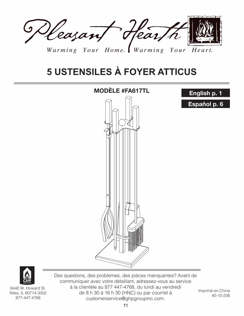
5 USTENSILES À FOYER ATTICUS
MODÈLE #FA617TL
Des questions, des problèmes, des pièces manquantes? Avant decommuniquer avec votre détaillant, adressez-vous au service
à la clientèle au 877 447-4768, du lundi au vendredide 8 h 30 à 16 h 30 (HNC) ou par courriel à
[email protected]é en China
40-10-236
6440 W. Howard St.Niles, IL 60714-3302
877-447-4768
English p. 1
Español p. 6

12
CONTENU DE L’EMBALLAGE
PIÈCE DESCRIPTION QUANTITÉA Tenez base 1B Cadre du porte-outils 1C Pinces 1D Pelle 1E Tisonnier 1F Brosse 1G Cintre 1H Partie supérieure 1
A
B
C
D
G
H
F
E

13
QUINCAILLERIE INCLUSE (grandeur réelle)
PRÉPARATION
CONSIGNES DE SÉCURITÉ
AVERTISSEMENT
Assurez-vous de lire et de comprendre l’intégralité du présent manuel avant de tenter d’assembler, d’installer ou d’utiliser l’article.
Avant de commencer l’assemblage du produit, assurez-vous d’avoir toutes les pièces. Comparez le contenu de l’emballage avec la liste des pièces et celle de la quincaillerie. S’il y a des piècesmanquantes ou endommagées, ne tentez pas d’assembler le produit.
Temps d’assemblage approximatif : 10 minutes
• Ne laissez pas les enfants jouer avec l’ensemble d’outils ou à proximité de celui-ci.• Ne tentez pas de nettoyer les outils lorsqu’ils sont chauds.• Il est possible que des particules brûlantes collent à la surface des outils.• LES OUTILS ET LEUR POIGNÉE PEUVENT ÊTRE BRÛLANTS DURANT ET APRÈS L’EMPLOI.• UTILISEZ DES GANTS RÉSISTANT À LA CHALEUR POUR MANIPULER LES OUTILS.
BoulonM6 X 20mm
Qté : 1
AA
OUTILS REQUIS POUR L’ASSEMBLAGE (non inclus)
Tournevis Phillips.

14
INSTRUCTIONS POUR L’ASSEMBLAGE
Quincaillerie utilisée
1. Pour fixer le tenez base (A) au cadre du porte-outilis (B) d’un côté, insérez un boulon (AA) dans les trous prépercés du tenez base (A) et dans le cadre du porte- outilis (B). Tourner dans le sens horaire boulon (AA) avec le tournevis pour serrer. Ne serrez pas trop.
2. Fixez le support de soutien (G) sur le cadre de support (B) en insérant l’extrémité filetée de la barre supérieure (H) à travers le trou percé dans le support de soutien (G). Tournez le support supérieur (H) dans le sens horaire pour serrer. Ne pas trop serrer et briser le support (H).
3. Accrochez le tisonnier (E), les pinces (C), la pelle (D), et la brosse (F) sur le porte-outils comme il est illustré.
1
2
3
Boulon x 1AA
AA
A
B
C D
E
B
HG
F

15
ENTRETIEN• Utilisez un linge doux pour essuyer les outils et le porte-outils.• Ne tentez pas de nettoyer les outils lorsqu’ils sont chauds.• Rangez les outils dans un endroit frais, propre et sec.GARANTIE
Si cet article présente des défauts de matériaux ou de fabrication au cours de la première année suivant la date d’achat initiale, nous le réparerons ou le remplacerons à notre discrétion, sans frais. Pour commander des pièces ou effectuer une réclamation au titre de la garantie, composez le 1-877-447-4768, entre 8 h et 20 h (HNC), du lundi au vendredi. Cette garantie ne couvre pas les défauts résultant d’un usage inadéquat, anormal ou inapproprié, d’un accident ou d’une modifica-tion. Si vous n’observez pas toutes les instructions contenues dans le guide d’utilisation, cette garan-tie sera invalide. Le fabricant n’est pas responsable des dommages accessoires ou consécutifs. Certains États ou certaines provinces ne permettent pas l’exclusion ou la limitation des dommages accessoires ou consécutifs, de sorte que la limitation ou l’exclusion des dommages accessoires ou consécutifs mentionnées ci-dessus peuvent ne pas s’appliquer à vous. Cette garantie vous confère des droits précis. Il est possible que vous disposiez également d’autres droits, qui varient d’un État ou d’une province à l’autre.LISTE DES PIÈCES DE RECHANGE
Pour obtenir des pièces de rechange, communiquez avec notre service à la clientèle au 1-877-447-4768, entre 8 h et 20 h (HNC), du lundi au vendredi.
A
B
C
D
G
H
F
E
I
J
PIÈCE DESCRIPTION NO DE PIÈCEA Tenez base 40-01-676B Cadre du porte-outils 40-01-677C Pinces 40-01-678D Pelle 40-01-679E Tisonnier 40-01-680F Brosse 40-01-681G Cintre 40-01-682H Partie supérieure 40-01-683I Capuchon de brosse 40-01-684J Tête de brosse 40-01-685
AA Paquet de Matériel 40-09-502N/A Manuel d’instructions 40-10-236
AA