| 'A ttach a resume of person's training and esperience as ...
EM163-PNCV-TD-203 0 PROJECTS & DEVELOPMENT INDIA LTD DOCUMENT NO REV
SHEET 1 OF 2
� � � � � � �� � � � � � �� � � � � � �
0� 17.11.2015� 17.11.2015� ISSUED�FOR�IMPLEMENTATION� RU/RRB� VP� RVV�REV REV DATE EFF DATE PURPOSE PPD REVWD APPD
FORM NO: 02-0000-0021F1 REV2 All rights reserved�
ATTACHMENT - X
SPECIFICATIONS AND SOR
FOR
CIVIL, STRUCTURAL & OTHER ALLIED WORKS
FOR
INSTALLATION OF MOUNDED BULLETS
AT
NUMALIGARH REFINERY LIMITED
CLIENT: NRL
CONSULTANT: PDIL

TENDER DOCUMENT FOR CIVIL, STRUCTURAL AND OTHER ALLIED WORKS FOR BALANCE
OF PLANT AT NRL, NUMALIGARH
EM163-PNCV-TD-203 0 DOCUMENT NO REV
SHEET 2 OF 2
FORM NO: 02-0000-0021F1 REV2 All rights reserved
CONTENT��
�������
SL. No. �
DESCRIPTION�
DOCUMENT NO.
1.0GENERAL SPECIFICATION FOR CIVIL, STRUCTURAL & OTHER ALLIED WORK
EM163-PNCV-GS-203
2.0TECHNICAL SPECIFICATION FORCIVIL, STRUCTURAL & OTHER ALLIED WORK
EM163-PNCV-TS-203
3.0TECHNICAL SPECIFICATION FORROAD WORK
EM163-PNCV-RD-203
4.0 PREAMBLE TO SOR FOR CIVIL, STRUCTURAL & OTHER ALLIED WORK
EM163-PNCV-PR-203
5.0 SCHEDULE OF RATES FOR CIVIL, STRUCTURAL & OTHER ALLIED WORK
EM163-PNCV-SOR-203

PRO
________FORM N
0REV
JECTS &
___________UMBER 02-0
CIV
17.11.15 DATE
& DEVEL
____________000-0021 F1
G
VIL, STR
INSTAL
FOR I
LOPMEN
____________REV 0
GENERA
RUCTUR
LLATIO
IMPLEMENPURPOS
T INDIA
____________
AL SPE
FO
RAL & O
FO
ON OF M
NTATIONSE
LTDEM
DOSh
___________
ECIFICA
OR
OTHER
OR
MOUNDE
RU/RPREPA
M163-PNCV-
OCUMENT. Nheet 1 of 5
____________
ATIONS
ALLIED
ED BUL
RRBARED R
-GS-203
NO.
____________All r
D WORK
LLETS
VPEVIEWED
0
REV
____________ights reserved
KS
RVVAPPROV
V
____d
VED

________FORM N
Sl
1 .
1.0
1.0
Sl
GENFO& O
___________UMBER 02-0
. No.
.00.0
02.00
02.1.1
. No.
1
2
3
NERAL SPOR CIVIL, SOTHER AL
____________000-0021 F2
GENE
SCOP
CIVIL,ALLIE
Boreh
Tende
Clause
PECIFICATSTRUCTULLIED WO
____________REV 0
D
ERAL
PE OF W
STRUCD WOR
A
ole Rec
er Drawi
e for Ste
TIONS URAL ORKS
____________
CONTE
Descript
WORK
CTURALRKS
ATTACH
ord
ngs
eel & Ce
EM163DOCUSheet
___________
ENTS
tion
L & OTH
HMENTS
Descrip
ement
3-PNCV-GS-MENT. NO.2 of 5
____________
HER
S
ption
-203
____________All r
She
0REV.
____________ights reserved
et Numb
3
3
4
____d
ber

________FORM N
1 . 00.01 . 01.1
1.01.2
1.01.3
1.01.4
1.02.001.02.01
1.02.02
GENFO& O
___________UMBER 02-0
0 GENER1 This se
Specifion ItemgroundBulletsIn the specificof the E
The Cosatisfy the fornecessand incontingUnder otherw
4 Works requireexistingany danegligeshall bOwnermeasufacilitie
0 SCOPE1 The Sc
Works INSTAwithin/oMound
2 The womateriaconstruincidennecessstrictly
NERAL SPOR CIVIL, SOTHER AL
____________000-0021 F2
RAL ection of thcations ne
m Rate bad level for cs as per the
event of ccations/ DoEngineer-inontractor shimself bem and natsary for sun general gencies anno circum
wise on the covered h
ed. The Cog equipmeamage ocence, ignobe made gr / Consultre, at his
es of the ex
E OF WORcope of Wlike pipe
ALLATIONoutside th
ded bullets ork to be pals exceptuction equntal items sary for su
in accord
PECIFICATSTRUCTULLIED WO
____________REV 0
he tender Deeded for tsis. The wcivil and ote items indconflict betocuments,n-Charge sshall inspeefore submture of theccessful c
shall himnd other cistances, epart of the
herein beloontractor sent, structuccurs duerance, acc
good by thtant. The Cown cost,
xisting plan
RKWork consis
rack, pumOF MOU
he battery is outside
performed t if indicauipment, to
though nccessful co
dance with
TIONS URAL ORKS
____________
Documentshe executi
work shall hther allied wdicated in thtween the the more shall prevaect and exmitting his be site, the qompletion mself obtarcumstanc
extra payme Contractoow may hashall have ures, facilite to the acidental ore ContracContractor to avoid a
nt.
sts of themp house,UNDED BU
limits ofthe purvieunder the
ated in Scools, tack
not indicatompletion the "Goo
EM163DOCUSheet
___________
s deals maion and cohave to beworks assohe "Schedrequireme
stringent rail. xamine thebid as to thquantum aof the wor
ain all neces which
ment conseor shall be ave to be to take allties and buactivities r any othector at his r shall havany harm/
execution, switch gULLETS A
plant. Thew of this c
Scope of Wchedule O
kles and pted or speof the wor
od for Con
3-PNCV-GS-MENT. NO.3 of 5
____________
ainly with onstruction e carried oociated witule of Rateents of tworequiremen
e site and he nature oand the narks and theecessary may influe
equent on aallowed. executed safety preuildings etof the Cor reasons own cost
ve to take injury to h
/ construcear room,
AT NRL, he construcontract. Work cons
Of Rates, plants, supecified, burk includingnstruction"
-203
____________All r
the Scopeof civil & s
out both beth Installates".o or morent as per th
its surrounof the grou
ature of woe means oinformation
ence or affany misun
also in opecaution toc. from daontractor whatsoeveto the satalso all nehis worker
ction of C etc assoNUMALIGuction of
sists of prosupervisio
pplies, traut reasonag ContractDrawings
0REV.
____________ights reserved
e and Techstructural welow and aion of Mou
e clauses ohe interpre
nding and und and suork and maof access tn as to fect his Tederstandin
perating plao protect aamage. In on accouer, the datisfaction oecessary srs and staf
ivil & Struociated witARH propmound fo
oviding all on, scaffo
ansportatioably implieor's supervto be sup
____d
hnical works above unded
of the tation
shall ubsoil, aterial o site risks,
ender. ngs or
ant, if all the case,
unt of mage of the safety ff and
ctural h the posed or the
labor, olding, n, all ed or vision pplied

________FORM N
1.02.0.
1.02.1.
1.02.1.
GENFO& O
___________UMBER 02-0
progresof RateequipmThe coas per gradingimportestruttinstructuearth/sexcavaconcreconstruany soincludeflooringproof tunservattacheperformprelimifinal Dr
.3 The scoreinforc
.0 The ciMOUN
.1 CIVIL,
TheneceskilleplantstrucINSTcarrieshallPreaenclobut n� S
NERAL SPOR CIVIL, SOTHER AL
____________000-0021 F2
ssively by es" of this
ment shall ontractor sh
BIS requig and leved selecteg, etc., excres and p
sand, cohated surplueting incluuction of reort of antices dismang, plasterinreatment w
viceable med with thmed undenary Drawrawings orope of wocements inivil work i
NDED BUL
, STRUCTscope of
essary enged and unts, tools actural workTALLATIONed out bot be carrie
amble to scosed with not limited Structure f
PECIFICATSTRUCTULLIED WO
____________REV 0
the Ownes Tender obe done ahall preferarements. Teling of th
ed good ecavation inplinth fillinesive nonus earth/ muding reineinforced ccorrosivetling and/ong, brick mworks incluaterials &
his specificer the scowings whichr show the ork also inncluding gencluded inLETS con
URAL ANf work ungineering sskilled labnd tackles
ks in balanN OF MOth below aed out strichedule of this documto, the follo
for Pipe ra
TIONS URAL ORKS
____________
er/ Consultaon Item R
as per relevably establThe naturehe site arearth unden trenches ng with avn-swelling materials, nforcementcement conpainting aor demolismasonry, rouding stacrebuilding
cation provope of thh are for bifull range
ncludes pretting themn this connsists of the
D OTHERnder this supervisionbor, etc. ans, equipmence of plan
OUNDED Band abovectly in accrates and
ment. The owings. ack
EM163DOCUSheet
___________
ant, "TechRate basis.vant clauslish a labo
e of work srea by excer desiredfor founda
vailable exsoil and
breaking ts and fncrete coluand/ or linshing of eolling shut
cking sepag as per revides a ghis Contradding purpof the workreparation
m Approvedntract fore following
R ALLIED Wincludes
n through nd mobilizent, machint for succBULLETS. ground lecordance "Schedulecivil works
3-PNCV-GS-MENT. NO.4 of 5
____________
hnical Spec. Samplinges of BIS ratory at sshall genercavation a compacti
ations, bacxcavated/
sand as/stripping formwork,
umns, slabsing on PC
existing PCtters, any rately servequiremeneneral ideact. The poses onlyk under theof Bar B
d from the the propo
gs:-
WORKSconstructioqualified
zation of aneries, etccessful comThe abov
evel. All thwith the "
e of Rates s for the P
-203
____________All r
cifications"g & testing& shall noite for all rerally involvand filling ion, dewak-filling aroimported
s specifie& forming
inserts, s, equipmeCC, RCC CC/RCC, ssort of roo
vice- able ts. The Te
ea about tenclosed
y and are be scope.
Bending ScEngineer-i
osed INST
on/ execuand techn
all relevantc., to carrympletion ove work shhe civil & s"Technical(EM163-P
Project con
0REV.
____________ights reserved
" and "Schg of mate
ot be paid eelevant sit
ve earth wowith avai
tering, shoound compselected
d, disposg of pile h
anchorent foundaThe work
structural ofing with wand disposender Drawthe work t
Drawingsby no mean
chedule foin-Charge.
TALLATION
ution, provnical persot and adeqy out all cof the prophall have structural w
SpecificaNCV-SOR
nsists of, m
____d
edule rial & extra. e test ork in lable/ oring, pleted good
sal of eads, bolts,
ations, k also steel, water sal of wings to be s are ns the
or the .N OF
viding onnel, quate civil & posed to be works
ations,R-203) mainly

________FORM N
1.02.1.
GENFO& O
___________UMBER 02-0
� S� R� F� P� R� M
.2 MATEMake/ braannexure
NERAL SPOR CIVIL, SOTHER AL
____________000-0021 F2
Structure fRCC FrameFoundationPavement Roads, DraMiscellane
ERIALS OFands of Ce of the ten
PECIFICATSTRUCTULLIED WO
____________REV 0
for Pump Hed buildinn for new
ains, cableeous civil w
F CONSTRement, Reider docum
TIONS URAL ORKS
____________
House ng (Single equipmen
e trench, pworks
RUCTIONnforcemen
ment.
*****
EM163DOCUSheet
___________
storey) nts and pu
pits
nt and Stru
************
3-PNCV-GS-MENT. NO.5 of 5
____________
umps
uctural stee
*
-203
____________All r
el shall be
0REV.
____________ights reserved
as per rel
____d
evant


EM163-PNCV-TS-203 1
PROJECTS & DEVELOPMENT INDIA LTD DOCUMENT NO REV
SHEET 1 OF 36
1 17.11.15 17.11.15 ISSUED FOR IMPLEMENTATION RU/RRB VP RVV 0 13.10.15 13.10.15 ISSUED FOR IMPLEMENTATION RU/RRB VP RVV
REV REV DATE EFF DATE PURPOSE PREPD REVWD APPD FORM NO: 02-0000-0021F1 REV2 All rights reserved�
TECHNICAL SPECIFICATIONS
FOR
CIVIL, STRUCTURAL & OTHER ALLIED WORKS

TECHNICAL SPECIFICATIONS EM163-PNCV-TS-203 1
FOR DOCUMENT NO REV
CIVIL & STRUCTURAL WORKS SHEET 2 OF 36
FORM NO: 02-0000-0021F2 REV1 All rights reserved�
CONTENTS
Sl. No. Description Sheet Number
1. GENERAL 3
2. REFERENCE CODES AND STANDARDS 3
3. EARTH WORK 4
4. PLAIN AND REINFORCED CONCRETE WORK 8
5. STEEL REINFORCEMENT 14
6. FORM WORK 15
7. BRICK WORK 17
8. WOOD WORK 19
9. STRUCTURAL STEEL WORK 19
10. PAINTING ON STRUCTURAL STEEL 24
11. M.S. GALVANISED GRATING 29
12. ALUMINIUM GRATING 29
13. STEEL/ALUMINIUM DOORS,WINDOWS AND VENTILATORS 30
14. NON-ASBESTOS SHEETS FOR ROOFING AND CLADDING.
30
15. FLOORING AND PAVING 30
16. PLASTERING 31
17. WHITE & COLOUR WASHING, CEMENT PAINTING 32
18. GLAZING 33
19. PROTECTIVE COATING AND LINING SYSTEM 34
20. CULVERT WORK 36
21. STORM WATER DRAIN 37

TECHNICAL SPECIFICATIONS EM163-PNCV-TS-203 1
FOR DOCUMENT NO REV
CIVIL & STRUCTURAL WORKS SHEET 3 OF 36
FORM NO: 02-0000-0021F2 REV1 All rights reserved�
1.0 GENERAL
1.1 Specifications of materials and workmanship shall be as described in the Central Public Works Department Specifications Vol. I to VI (latest) including latest amendments, unless otherwise specified. These CPWD Specifications shall be deemed to form part of this contract. The CONTRACTOR shall procure and maintain copies of the latest CPWD Specifications at site for reference.
1.2 These technical Specifications shall be supplementary to the specifications contained in the CPWD specifications, wherever at variance, these Particular Specifications shall take precedence over the provisions in the CPWD Specifications.
1.3 Site clearing - Site clearing means the cutting of trees, bushes, shrubs etc. and the pulling out of roots and stumps to effect a general cleaning of the site area. All these materials shall be removed from the site area at the CONTRACTOR's expenses and responsibility and shall be disposed off as directed by Engineer-in-Charge. Trees, bushes, roots, stumps and other materials shall not be disposed off by burning within the site boundaries..
2.0 REFERENCE CODES & STANDARDS
2.1 Wherever reference of BIS Specifications/ or BIS Codes of Practice are made in the Specifications/ Schedule of Rates or Preambles, reference shall be to the latest edition of BIS (Bureau of Indian Standards).
BIS - 383 Coarse & Fine aggregates from natural sources for concrete.
BIS - 432 Mild Steel & Medium tensile steel bars.
BIS - 456 Code of Practice for Plain and Reinforced Concrete.
BIS - 515 Natural and Manufactured aggregates for use in mass concrete
BIS - 1363 Hexagon head bolts, screws & nuts of product grade C : Part - I Hexagon head bolts ( size range M5 to M64)
BIS - 1367 Technical supply conditions for threaded steel fasteners
BIS - 1566 Hard - Drawn steel wire fabric for concrete reinforcement.
BIS - 1786 High strength deformed steel bars & wires for concrete reinforcement.
BIS - 2116 Sand for masonry mortars.
BIS - 2212 Code of practice for brickwork.
BIS - 2386 Methods of test for aggregates.
BIS - 4925 Concrete batching and mixing plant.
BIS - 10262 Recommended guidelines for concrete mix design. �

TECHNICAL SPECIFICATIONS EM163-PNCV-TS-203 1
FOR DOCUMENT NO REV
CIVIL & STRUCTURAL WORKS SHEET 4 OF 36
FORM NO: 02-0000-0021F2 REV1 All rights reserved�
3.0 EARTHWORK
3.1 EXCAVATION
3.1.1 Excavation shall be carried out in soil of any nature and consistency, in the presence of water or in the dry, met on the site to the lines, levels and contours shown on the detailed drawings and CONTRACTOR shall remove all excavated materials to soil heaps on site or transport for use in filling on the site or stack them for reuse as directed by the Engineer-in-Charge.
3.1.2 Surface dressing shall be carried out on the entire area occupied by the buildings including plinth protection as directed without any extra cost. The depths of excavation shown on the drawings are the depths after surface dressing.
3.1.3 The site around all buildings and structures to a width of 3 metres beyond the edge of plinth protection, ramps, steps, etc. shall be dressed and sloped away from the buildings.
3.1.4 Black cotton soil, and other expansive or unsuitable soils excavated shall not be used for filling in foundations, and plinths of buildings or in other structures including manholes, septic tanks etc. and shall be disposed off within the contract area marked on the drawings, as directed, leveled and neatly dressed.
3.1.5 In case of trenches exceeding 2 metres depth or where soil is soft or slushy, the sides of trenches shall be protected by timbering and shoring. The CONTRACTOR shall be responsible to take all necessary steps to prevent the sides of trenches from caving in or collapsing. The extent and type of timbering and shoring shall be as directed by the Engineer-in-Charge.
3.1.6 Where the excavation is to be carried out below the foundation level of adjacent structure, the precautions to be taken such as under pinning, shoring and strutting etc. shall be determined by Engineer-in-Charge. No excavation shall be done unless such precautionary measures are carried out as per directions of Engineer-in-Charge.
3.1.7 Specification for Earth work shall also apply to excavation in rock in general. The excavation in rock shall be done such that extra excavation beyond the required width and depth as shown in drawings is not made. If the excavation done in depth greater than required /ordered. The CONTRACTOR shall fill the extra excavation with concrete of mix 1:5:10 as the foundation concrete at his own cost.
3.1.8 CONTRACTOR shall make all necessary arrangements for dewatering / defiling as required to carry out proper excavation work by bailing or pumping out water, which may accumulate in the excavation pit from any cause/ source whatsoever.
3.1.9 CONTRACTOR shall provide suitable draining arrangements at his own cost to prevent surface water entering the foundation pits from any source.
3.1.10 The CONTRACTOR is forbidden to commence the construction of structures or to carry out concreting before Engineer-in-Charge has inspected, accepted and permitted the excavation bottom.

TECHNICAL SPECIFICATIONS EM163-PNCV-TS-203 1
FOR DOCUMENT NO REV
CIVIL & STRUCTURAL WORKS SHEET 5 OF 36
FORM NO: 02-0000-0021F2 REV1 All rights reserved�
3.1.11 Excavation in disintegrated rock means rock or Boulders including brickbats which may be quarried or split with crow bars. This will also include laterite and hard conglomerate.
3.1.12 Excavations in hard rock - means excavation made in hard rock to be done manually, or by blasting using only explosives and / or pneumatic hammers. In case of blasting, control blasting should be adopted depending on site conditions. For using explosives CONTRACTOR shall follow all provisions of Indian Explosives Act / Rules 1983, corrected / revised up to date.
3.1.13 In case of hard rock excavation to be carried out using explosives the, CONTRACTOR shall obtain the written approval in advance.
3.1.14 The measurements for excavations shall be restricted and limited to minimum excavation line as per drawing for payment purposes. Excavation beyond the edge of PCC marked in the drawing shall not be paid for.
3.1.15 Adequate protective measures shall be taken to see that the excavation does not affect or damage adjoining structures. The CONTRACTOR shall take all measures required for ensuring stability of the excavation and safety of property and people in the vicinity. The CONTRACTOR shall erect and maintain during progress of work, temporary fences around dangerous excavations at no extra cost.
3.1.16 Excavation in ordinary soil means excavation in ordinary hard soil including stiff heavy clay, hard shale, or compact murum, or any material, which can be removed by the ordinary application of spades, shovels, picks and pick axes. This shall also include removal of isolated boulders each having a volume not more than 0.50m³.
3.1.17 Excavation in soft rock includes limestone, sandstone, laterite, hard conglomerates, etc. or other rock which can be quarried or split with crowbars or wedges. This shall also include excavation of tarred pavements, masonry work and rock boulders each having a volume of not more than 0.25m³.
3.1.18 Excavation in hard rock includes any rock bound in ledges or masses in its original form or cement concrete for which in the opinion of the Engineer-in-Charge,requires the use of compressed air, equipment, sledge hammer and blasting or non-explosive materials viz. Acconex manufactured by A.C.C. Ltd. Specifications and instructions for use shall be as per manufacturer.
3.1.19 In case of any difficulty concerning the interpretation of type of soil as mentioned above, the Engineer-in-Charge shall decide whether the excavation in a particular material is in ordinary soil, soft rock or hard rock and his decision in this matter shall be final and binding on the CONTRACTOR and without appeal.
3.2 FILLING
3.2.1 Back filling of excavations in trenches, foundations and elsewhere shall consist of one of the following materials approved by Engineer-in-Charge.

TECHNICAL SPECIFICATIONS EM163-PNCV-TS-203 1
FOR DOCUMENT NO REV
CIVIL & STRUCTURAL WORKS SHEET 6 OF 36
FORM NO: 02-0000-0021F2 REV1 All rights reserved�
i. Soil
ii. Sand
iii. Moorum
iv. Hard-core
v. Stone/gravel
All back filling material shall be approved by the Engineer-in-Charge.
3.2.2 Soil filling - Soil material shall be free from rubbish, roots, hard lumps and any other foreign organic material. Filling shall be done in regular horizontal layers each not exceeding 20 Cm. depth.
3.2.3 Back filling around completed foundations, structures, trenches and in plinth shall be done to the lines and levels shown on the drawings.
3.2.4 Back filling around pipes in the trench shall be done after hydro testing is done.
3.2.5 Back filling around liquid retaining structures shall be done only after leakage testing is completed and approval of Engineer-in-Charge is obtained.
3.2.6 Sand used for filling under foundation concrete, around foundation and in plinth etc. shall be fine/ coarse, strong, clean, free from dust, organic and deleterious matter. The sand filling under foundation shall be rammed with Mech. compactor. Sand material shall be approved by Engineer-in-Charge.
3.2.7 Moorum for filling, where ordered, shall be obtained from approved pits and quarries which contain siliceous material and natural mixture of clay. Moorum shall not contain any admixture of ordinary earth. Size of moorum shall vary from dust to 10 mm.
3.2.8 Hard-core shall be of broken stone of 90 mm to 10 mm size suitable for providing a dense and compact sub grade. Stones shall be sound, free from flakes, dust and other impurities. Hard core filling shall be spread and leveled in layers, 15 cm thick, watered and well compacted with ramming or with mechanical / hand compacts including hand packing wherever required.
3.2.9 If any selected fill material is required to be borrowed, CONTRACTOR shall make arrangements and procure such material from outside borrow pits. The material of source shall be subject to prior approval of Engineer-in-Charge. CONTRACTORshall make necessary access roads to borrow areas and maintain the same, if such access roads do not exist, at no extra cost.
3.2.10 Plinth filling shall be carried out with approved material as described earlier, in layers not exceeding 150mm, watered and compacted with mechanical compaction machines. Engineer-in-Charge may however permit manual compaction by hand tampers in case he is satisfied that mechanical compaction is not possible. When filling reaches the finished level, the surface shall be flooded with water, unless otherwise directed, for at least 24 hours, allowed to dry and then the surface again compacted as specified above to avoid settlements at later stage. The finished

TECHNICAL SPECIFICATIONS EM163-PNCV-TS-203 1
FOR DOCUMENT NO REV
CIVIL & STRUCTURAL WORKS SHEET 7 OF 36
FORM NO: 02-0000-0021F2 REV1 All rights reserved�
level of the filling shall be trimmed to the level specified. Compacted surface shall have at least 95% of laboratory maximum dry density. A minimum of one test per 500 sq. meters of compacted area shall be done.
3.2.11 Whenever the fill material (earth or soil) is purchased, CONTRACTOR shall get the approval of Engineer-in-Charge. The CONTRACTOR shall arrange to determine the following properties of the soil and shall get the approval of Engineer-in-Charge.
Clay content : 15% to 20%
Laboratory dry density : Not less than 1600 kg/m³
Plasticity Index : Not more than 20.
3.2.12 The fill shall be compacted using a vibrating compactor of not less than 1.5 tonne. The fill shall be thoroughly compacted in layers as directed but not more than 200 mm thick. Adequate water shall be used for compaction and the density after compaction shall be not less than maximum dry density obtained in test of BIS: 2720 Part-8. Compacted surface shall have at least 90% of laboratory maximum dry density. A minimum of one test per 500 sq. meters of compacted area shall be done.
3.2.13 The Gravel fill shall be non plastic granular material, well graded, strong, with maximum particle size of 50 mm, with not more than 15% passing a 4.75 mm BIS sieve, free of all debris, vegetable matter and chemical impurities.
3.2.14 All clods, lumps etc. shall be broken before compaction.
3.2.15 In case of grading/banking successive layers of filling shall not be placed, until the layer below has been thoroughly compacted to satisfy the requirements laid down in this specification.
Prior to rolling, the moisture content of material shall be brought to within +/-2% of the optimum moisture content as described in BIS 2720 Part-7. The moisture content shall preferably be on the wet side for potentially expansive soil.
After adjusting the moisture content as described, the layers shall be thoroughly compacted by means approved by Engineer-in-Charge, till the specified maximum laboratory dry density is obtained.
General, fill shall be placed in layers not exceeding 300 mm thickness and shall be thoroughly compacted to achieve a compaction of at least 90% of laboratory maximum dry density up to a depth of 600 mm below finished grade. Final fill of 600 mm thickness shall consist of preferably natural material in, as dug condition except that stones larger than 100 mm shall be removed. It shall be placed in layers not exceeding 150 mm thickness and compacted to achieve of at least 95% of laboratory maximum dry density. Each layer shall be tested in field for density and accepted by Engineer-in-Charge, subject to achieving the required density before laying the next layer. A minimum of one test per 500 sq meters for each layer shall be conducted.

TECHNICAL SPECIFICATIONS EM163-PNCV-TS-203 1
FOR DOCUMENT NO REV
CIVIL & STRUCTURAL WORKS SHEET 8 OF 36
FORM NO: 02-0000-0021F2 REV1 All rights reserved�
If the layer fails to meet the required density, it shall be reworked or the material shall be replaced and method of construction altered as directed by Engineer-in-Charge to obtain the required density.
The filling shall be finished in conformity with the alignment, levels, cross-section and dimensions as shown in the drawing.
Extra material shall be removed and disposed off as directed by the Engineer-in-Charge.
4.0 PLAIN AND REINFORCED CONCRETE WORK
This specifications deals with cement concrete, plain or reinforced, for general use, and covers the requirements for concrete materials, their storage, grading, mix design, strength & quality requirements, pouring at all levels, reinforcements, protection, curing, form work, finishing, painting, admixtures, inserts and other miscellaneous works.
4.1 MATERIALS
4.1.1 Cement: Any of the following cements may be used as required.
BIS - 269 Ordinary Portland cement, 33 grade
BIS - 8041 Rapid hardening Portland cement
BIS - 455 Portland slag cement
BIS - 8112 43 Grade ordinary Portland cement
BIS - 12330 Sulphate resistant ordinary Portland cement
BIS - 12269 53 Grade ordinary port land cement
BIS - 6909 Specifications for super Sulphate cement
4.1.2 Water: Water used for mixing and curing concrete and mortar shall conform to the requirements as laid down in BIS: 456. Sea water shall not be used for concrete work.
4.1.3 Aggregates: Coarse and fine aggregates for cement concrete plain and reinforced shall conform to the requirements of BIS 383 and / or BIS 515. Before using, the aggregates shall be tested as per BIS: 2386.
Coarse aggregate: Coarse aggregate for all cement concrete work shall be broken or crushed hard stone, black trap stone obtained from approved Quarries or gravel.
Sand: Fine aggregate for concrete work shall be coarse sand from approved sources. Grading of coarse sand shall be within grading zones I, II or III laid down in BIS: 383, table 4. If required the aggregates (both fine and coarse) shall have to be thoroughly washed and graded as per direction of Engineer-in-Charge.

TECHNICAL SPECIFICATIONS EM163-PNCV-TS-203 1
FOR DOCUMENT NO REV
CIVIL & STRUCTURAL WORKS SHEET 9 OF 36
FORM NO: 02-0000-0021F2 REV1 All rights reserved�
4.2 MIXING
All cement concrete plain or reinforced shall be machine mixed. Mixing by hand may be employed where quantity of concrete involved is small, with the specific prior permission of the Engineer-in-Charge. 10% extra cement shall be added in case of hand mixing as stipulated in BIS-456.
For large and medium project sites the concrete shall be sourced from ready- mixed concrete plants or from on site or off site batching and mixing plants (BIS 4926)
4.3 WATER CEMENT RATIO
Once a mix, including its water-cement ratio, has been determined and specified for use by the Engineer-in-Charge, that water cement ratio shall be maintained.
4.4 LAYING
Concreting shall be commenced only after the Engineer-in-Charge has inspected and passed the sub-base / base or the centering, shuttering and reinforcement. Concrete in slab beams, columns, footings etc. shall be laid gently in layers not exceeding 15 cm and shall be properly consolidated by means of approved mechanical vibrators.
4.5 CURING
a. After the concrete has begun to harden, it shall be protected with moist gunny bags, sand or any other material approved by the Engineer-in-Charge against quick drying. After 24 hours of laying concrete, the surface shall be cured by flooding with water or by covering with wet absorbent materials for 7 days as per the direction of Engineer-in-Charge.
b. Approved curing compounds may be used in lieu of moist curing with the permission of the Engineer-in-Charge. Such compounds shall be applied to all exposed surfaces of the concrete as soon as possible after the concrete has set. No extra payment shall be made for the same.
4.6 GRADES OF CONCRETE
4.6.1 Grades of cement concrete shall be as given below:
Grade Specified Characteristic compressive strength at 28 days ( N/mm2)
i. M 7.5 7.5 ( 75 Kg/cm2 )
ii. M 10 10 ( 100 Kg/cm2 )
iii. M 15 15 (150 Kg/cm2 )
iv. M 20 20 ( 200 Kg/cm2 )

TECHNICAL SPECIFICATIONS EM163-PNCV-TS-203 1
FOR DOCUMENT NO REV
CIVIL & STRUCTURAL WORKS SHEET 10 OF 36
FORM NO: 02-0000-0021F2 REV1 All rights reserved�
v. M 25 25 (250 Kg/cm2 )
vi. M 30 30 ( 300 Kg/cm2 )
4.6.2 Grades lower than M 20 shall not be used in reinforced concrete.
4.6.3 M 7.5 grades of concrete may be used for lean concrete bases & M 10 for simple foundation of masonry walls.
4.6.4 A sieve analysis test of aggregates shall be carried out as and when the source of supply is changed without extra charge not withstanding the mandatory test required to be carried out as per CPWD specification.
4.6.5 All test in support of mix design shall be maintained as a part of records of the contract. Test cubes for mix design shall be prepared by the CONTRACTOR under his own arrangements and at his costs, but under the supervision of the Engineer-in-Charge
4.7 NOMINAL MIX CONCRETE
4.7.1 All concrete work (P.C.C / R.C.C.) shall be with nominal mix concrete unless specified otherwise. The proportions of materials used for concrete of grades M5, M 7.5, M10, M15 and M20 shall be as per following Table.
Proportions for Nominal Mix of Concrete
Grade of Concrete
Total Quantity of Dry Aggregate by Mass per 50 Kg of Cement (as sum
of Fine and coarse
aggregates), in Kg, Max.
Proportion of Fine Aggregate to coarse aggregate ( by Mass)
Quantity of water per 50 Kg of cement Maximum in
liters.
M 5 800
Generally 1:2 subject to an upper limit of
1 : 1.5 and a lower limit of 1 : 2.5
60
M 7.5 625 -do- 45
M 10 480 -do- 34
M 15 330 -do- 32
M 20 250 -do- 30
Notes:
TECHNICAL SPECIFICATIONS EM163-PNCV-TS-203 1
FOR DOCUMENT NO REV
CIVIL & STRUCTURAL WORKS SHEET 11 OF 36
FORM NO: 02-0000-0021F2 REV1 All rights reserved�
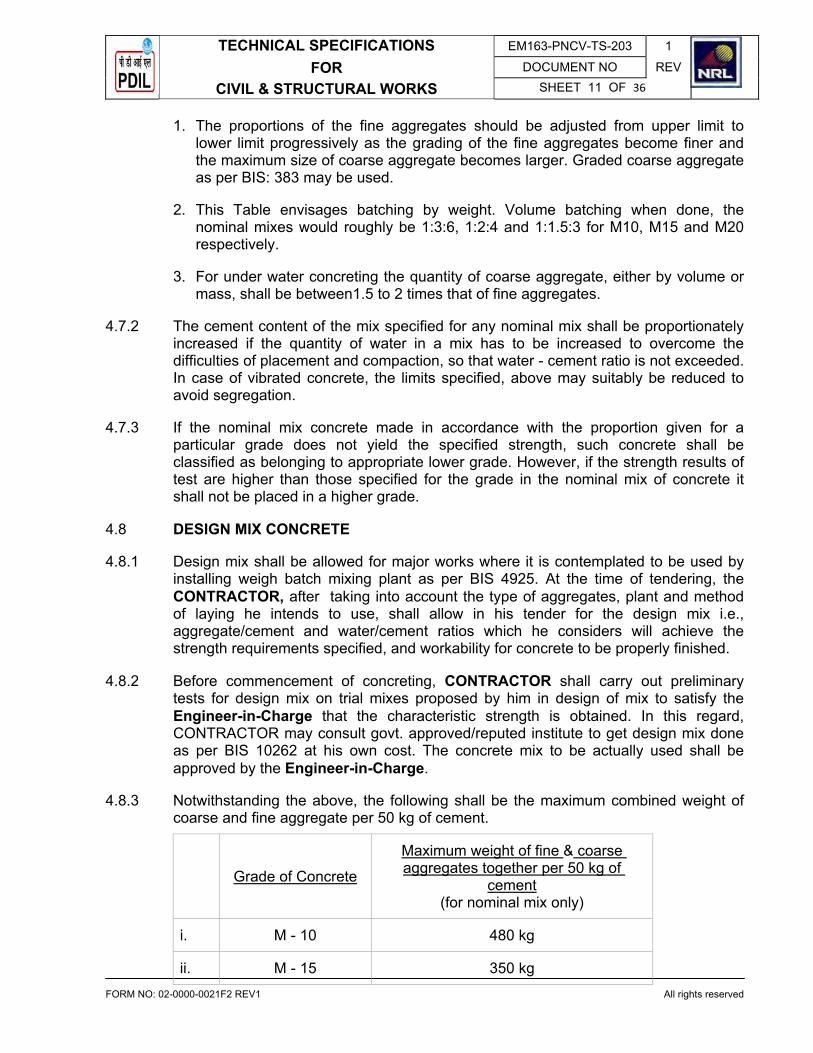
1. The proportions of the fine aggregates should be adjusted from upper limit to lower limit progressively as the grading of the fine aggregates become finer and the maximum size of coarse aggregate becomes larger. Graded coarse aggregate as per BIS: 383 may be used.
2. This Table envisages batching by weight. Volume batching when done, the nominal mixes would roughly be 1:3:6, 1:2:4 and 1:1.5:3 for M10, M15 and M20 respectively.
3. For under water concreting the quantity of coarse aggregate, either by volume or mass, shall be between1.5 to 2 times that of fine aggregates.
4.7.2 The cement content of the mix specified for any nominal mix shall be proportionately increased if the quantity of water in a mix has to be increased to overcome the difficulties of placement and compaction, so that water - cement ratio is not exceeded. In case of vibrated concrete, the limits specified, above may suitably be reduced to avoid segregation.
4.7.3 If the nominal mix concrete made in accordance with the proportion given for a particular grade does not yield the specified strength, such concrete shall be classified as belonging to appropriate lower grade. However, if the strength results of test are higher than those specified for the grade in the nominal mix of concrete it shall not be placed in a higher grade.
4.8 DESIGN MIX CONCRETE
4.8.1 Design mix shall be allowed for major works where it is contemplated to be used by installing weigh batch mixing plant as per BIS 4925. At the time of tendering, the CONTRACTOR, after taking into account the type of aggregates, plant and method of laying he intends to use, shall allow in his tender for the design mix i.e., aggregate/cement and water/cement ratios which he considers will achieve the strength requirements specified, and workability for concrete to be properly finished.
4.8.2 Before commencement of concreting, CONTRACTOR shall carry out preliminary tests for design mix on trial mixes proposed by him in design of mix to satisfy the Engineer-in-Charge that the characteristic strength is obtained. In this regard, CONTRACTOR may consult govt. approved/reputed institute to get design mix done as per BIS 10262 at his own cost. The concrete mix to be actually used shall be approved by the Engineer-in-Charge.
4.8.3 Notwithstanding the above, the following shall be the maximum combined weight of coarse and fine aggregate per 50 kg of cement.
Grade of Concrete
Maximum weight of fine & coarse aggregates together per 50 kg of
cement(for nominal mix only)
i. M - 10 480 kg
ii. M - 15 350 kg

TECHNICAL SPECIFICATIONS EM163-PNCV-TS-203 1
FOR DOCUMENT NO REV
CIVIL & STRUCTURAL WORKS SHEET 12 OF 36
FORM NO: 02-0000-0021F2 REV1 All rights reserved�
iii. M - 20 250 kg
4.8.4 The workability of concrete produced shall be adequate, so that the concrete can be properly placed and compacted. The slump shall be as per BIS 456.
4.8.5 The minimum consumption of the cement irrespective of design mix shall not be less than the following:
M 7.5 (1:4:8) 170 kg/cu m
M 10 (1:3:6) 220 kg/cu m
M 15 300 kg/cu m
M 20 350 kg/cu m
M 25 380 kg/cu m
M 30 400 kg/cu m
4.9 TESTING OF CONCRETE
4.9.1 Testing of concrete, sampling and acceptance criteria shall be in accordance with BIS 456.
4.9.2 A slump test shall be taken at each mixer at least once in every fifty batches mixed. Any batch for which a slump test is being made shall not be transferred to the place of laying until the slump test has been completed. Any batch which gives a slump in excess of that described at the time of preliminary tests shall be rejected and removed from the site.
4.9.3 At least six cubes shall be taken for every 30 cu. metres of concrete or part thereof deposited in the work on any day. Three cubes shall be tested for 28 days strength.
4.9.4 If a test for particular work does not meet the specified requirements, the Engineer-in-Charge, in his absolute discretion may accept the work at a correspondingly reduced rate provided the average strength at 28 days is not less than 85% of the specified strength.
4.9.5 If the results are poorer than 85% of the specified strength, the Engineer-in-Chargemay order further testing of any kind as may be deemed necessary in his opinion, including load tests. The load tests shall be carried on the portion of the structure involving concrete represented by the unsatisfactory works test and such other adjoining elements of a building as the Engineer-in-Charge may decide. If the results of the load tests are not satisfactory, the CONTRACTOR shall at his own cost undertake remedial measures including dismantling and reconstruction according to the directions and to the satisfaction of the Engineer-in-Charge. If the load test is successful, the Engineer-in-Charge may exercise his judgment before accepting or rejecting the work and shall still have the power to apply a reduction in rate as herein- stated before, in case the work in question is accepted.

TECHNICAL SPECIFICATIONS EM163-PNCV-TS-203 1
FOR DOCUMENT NO REV
CIVIL & STRUCTURAL WORKS SHEET 13 OF 36
FORM NO: 02-0000-0021F2 REV1 All rights reserved�
4.10 PROPORTIONING
Mixes of cement concrete shall be as ordered. Where the concrete is specified by grade, it shall be prepared by mixing cement, sand and coarse aggregate by weight as per mix design. In case the concrete is specified as volumetric mix, then dry
volume batching shall be done, making proper allowances for dampness in aggregates and bulking in sand. Equivalent volume batching for concrete specified by grade may however be allowed by the Engineer-in-Charge at his discretion.
4.11 PROTECTION OF CONCRETE
All concrete shall be protected from damage by rain or by workmen, equipment, overload or any other causes. All edges, corners and projections of concrete members likely to be damaged, shall be protected by means of wooden cover fillets.
4.12 CONSTRUCTION JOINTS
Construction joints shall be made only where shown on the drawings or as approved by the Engineer-in-Charge. The procedure given in clause 13.4 of BIS: 456 shall be followed for general guidance.
4.13 SEPARATION JOINT
Separation Joint shall be obtained by using an approved alkathene sheet struck on the surface against which concrete shall be placed. Adequate care should be taken to cause no damage to the sheet.
4.14 DAMP PROOF COURSES
Damp proof course shall consist of cement concrete of specified proportions and thickness. Surface of brick or stone masonry shall be leveled and prepared before laying the cement concrete.
4.15 SAMPLING OF CONCRETE
Sampling & strength Test of concrete, Acceptance criteria and Inspection & Testing of Structure : This shall be as per the requirements laid down in clause Nos: 14, 15 & 16 of BIS : 456.
5.0 STEEL REINFORCEMENT
5.1 Steel reinforcement shall comprise
i. Mild steel bars conforming to BIS : 432 Part-I.
ii. Cold twisted bars conforming to BIS: 1786
iii. CRS bars

TECHNICAL SPECIFICATIONS EM163-PNCV-TS-203 1
FOR DOCUMENT NO REV
CIVIL & STRUCTURAL WORKS SHEET 14 OF 36
FORM NO: 02-0000-0021F2 REV1 All rights reserved�
iv. TMT bars
v. Hard drawn steel wire fabric conforming to BIS: 1566
5.2 All joints in reinforcement shall be lapped adequately to develop the full strength of the reinforcement as per provision of BIS: 456 or as per instruction of Engineer-in-Charge.
As and when required, welded laps shall be provided as specified by Engineer-in-Charge. Following procedure shall be followed for welding of Tor steel reinforcement bars.
1. Welding of steel reinforcement bars shall be taken up only after specific approval by Engineer-in-Charge.
2. Lap welding with longitudinal beads shall only be adopted.
3. Welding shall be carried in accordance with BIS 2751 & 9417. Only qualified welders shall be permitted to carry out such welding.
4. For cold twisted reinforcement, welding operations shall be controlled to prevent a supply of large amount of heat, larger than can be disspated. The extreme non-twisted end portion shall be cut off before welding. Electrodes with rutile coating should be used.
5. Welding procedure shall be approved by Engineer-in-Charge and tests shall be made to prove the soundness of the welded connection
6. Stripper at closer spacing shall be provided in the lap welded joints as directed by Engineer-in-Charge.
5.3 M.S. round bars shall be hooked at ends as specified. Ribbed Tor-Steel shall be bent at right angles at ends as indicated or directed.
6.0 FORM WORK
6.1 The shuttering or form work shall conform to the shape, lines and dimensions as shown on the drawings and be so constructed as to remain sufficiently rigid during placing and compacting of the concrete and shall be sufficiently tight to prevent loss of liquid from the concrete. The surface that becomes exposed on the removal of forms shall be examined by Engineer-in-Charge or his authorized representative before any defects are made good. Work that has sagged or bulged out, or contains honey combing, shall be rejected. All shuttering shall be plywood or steel shuttering.
6.2 The CONTRACTOR shall be responsible for sufficiency and adequacy of all form work. Centering and form work shall be designed & detailed in accordance with BIS 14687 and approved by the Engineer-in-Charge, before placing of reinforcement and concreting.
6.3 STRIPPING TIME Forms shall not be struck until the concrete has reached a strength at least twice the
stress to which the concrete may be subjected at the time of removal of form work.

TECHNICAL SPECIFICATIONS EM163-PNCV-TS-203 1
FOR DOCUMENT NO REV
CIVIL & STRUCTURAL WORKS SHEET 15 OF 36
FORM NO: 02-0000-0021F2 REV1 All rights reserved�
The strength referred to shall be that of concrete using the same cement and aggregates, with the same proportions and cured under conditions of temperature and moisture similar to those existing on the work. Where possible, the form work shall be left longer as it would assist the curing.
Note 1 - In normal circumstances and where ordinary Portland Cement is used, forms may generally be removed after the expiry of the following periods:
a. Walls, columns and vertical faces of all structural members
24 to 48 hours as may be decided by the Engineer-in-Charge
b. Slabs (props left under) 3 days
c. Beam soffits (Props left under) 7 days
d. Removal of props under slabs
1. Spanning up to 4.5 m 7 days
2. Spanning over 4.5 m 14 days
e. Removal of props under beams and arches :
1. Spanning up to 6 m 14 days
2. Spanning over 6m 21 days �
7.0 BRICK WORK
This specification covers the construction of brick masonry in foundations, arches, walls, etc. at all elevations. The provision of BIS: 2212 shall be complied with unless permitted otherwise.
7.1 Bricks
Locally available first class bricks shall be used unless specified otherwise.
7.2 Mortar
7.2.1 Cement and water shall conform to the requirements laid down for cement concrete work.
7.2.2 Sand for masonry mortar shall be coarse sand conforming to BIS: 2116. Maximum quantities of clay, fine dust shall not be more than 5% by weight. Organic impurities shall not exceed the limits laid down in BIS: 2116.
7.2.3 Mix of mortar for building brick work shall be as specified in the item of work.
7.2.4 Mixing of mortar shall be done in a mechanical mixer. When quantity involved is small, hand mixing may be permitted by the Engineer-in-Charge. Any mortar remaining unused for more than 30 minutes after mixing shall be rejected.
TECHNICAL SPECIFICATIONS EM163-PNCV-TS-203 1
FOR DOCUMENT NO REV
CIVIL & STRUCTURAL WORKS SHEET 16 OF 36
FORM NO: 02-0000-0021F2 REV1 All rights reserved�
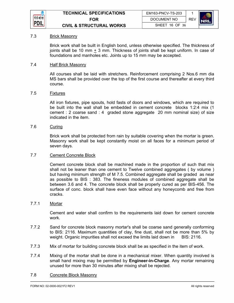
7.3 Brick Masonry
Brick work shall be built in English bond, unless otherwise specified. The thickness of joints shall be 10 mm + 3 mm. Thickness of joints shall be kept uniform. In case of foundations and manholes etc. Joints up to 15 mm may be accepted.
7.4 Half Brick Masonry
All courses shall be laid with stretchers. Reinforcement comprising 2 Nos.6 mm dia MS bars shall be provided over the top of the first course and thereafter at every third course.
7.5 Fixtures
All iron fixtures, pipe spouts, hold fasts of doors and windows, which are required to be built into the wall shall be embedded in cement concrete blocks 1:2:4 mix (1 cement : 2 coarse sand : 4 graded stone aggregate 20 mm nominal size) of size indicated in the item.
7.6 Curing
Brick work shall be protected from rain by suitable covering when the mortar is green. Masonry work shall be kept constantly moist on all faces for a minimum period of seven days.
7.7 Cement Concrete Block
Cement concrete block shall be machined made in the proportion of such that mix shall not be leaner than one cement to Twelve combined aggregates ( by volume ) but having minimum strength of M 7.5. Combined aggregate shall be graded as near as possible to BIS : 383. The fineness modules of combined aggregate shall be between 3.6 and 4. The concrete block shall be properly cured as per BIS-456. The surface of conc. block shall have even face without any honeycomb and free from cracks.
7.7.1 Mortar
Cement and water shall confirm to the requirements laid down for cement concrete work.
7.7.2 Sand for concrete block masonry mortar's shall be coarse sand generally conforming to BIS: 2116. Maximum quantities of clay, fine dust, shall not be more than 5% by weight. Organic impurities shall not exceed the limits laid down in BIS: 2116.
7.7.3 Mix of mortar for building concrete block shall be as specified in the item of work.
7.7.4 Mixing of the mortar shall be done in a mechanical mixer. When quantity involved is small hand mixing may be permitted by Engineer-in-Charge. Any mortar remaining unused for more than 30 minutes after mixing shall be rejected.
7.8 Concrete Block Masonry

TECHNICAL SPECIFICATIONS EM163-PNCV-TS-203 1
FOR DOCUMENT NO REV
CIVIL & STRUCTURAL WORKS SHEET 17 OF 36
FORM NO: 02-0000-0021F2 REV1 All rights reserved�
The thickness of joints shall be 10 mm +- 3mm. Thickness of joints shall be kept uniform. In case of foundation and manholes etc. joints up to 15 mm may be accepted.
7.9 Half Concrete Block
All courses shall be laid with stretchers. Reinforcement comprising 2 nos. 6 mm dia MS bars shall be provided over the top of the first course and thereafter at every fourth course.
7.10 Fixtures
All iron fixtures, pipes spouts, hold fasts of doors and windows which are required to be built into the wall shall be embedded in cement concrete blocks 1:2:4 mix (1 cement :2 coarse sand :4 graded stone aggregate. 20 mm nominal size) of size indicated in the item.
7.11 Curing
Concrete block masonry shall be protected from rain by suitable covering when mortar is green. Masonry work shall be kept constantly moist on all faces for a minimum period of seven days.
8.0 WOOD WORK
All materials workmanship for wood work shall conform to BIS : 883, it shall be good quality well seasoned second class Teak / Sal wood as approved by Engineer-in-Charge. The wood work shall conform to BIS: 4021.
9.0 STRUCTURAL STEEL WORK
This specification covers the technical requirements for the preparation of shop drawings, supply, fabrication, protective coating, painting and erection of all structural steel rolled sections, built up sections, plates and miscellaneous steel required for the completion of the work.
9.1 Steel
All structural steel used in construction within the purview of this contract shall, comply with one of the following Bureau of Indian Standard Specifications, whichever, is appropriate or as specified.
BIS – 2062 Hot rolled sections and plates
BIS – 1079 Cold formed light gauge sections
BIS – 1161 Tubular sections
BIS – 4923 Hollow sections (rectangular or square)
9.2 Smithy Works

TECHNICAL SPECIFICATIONS EM163-PNCV-TS-203 1
FOR DOCUMENT NO REV
CIVIL & STRUCTURAL WORKS SHEET 18 OF 36
FORM NO: 02-0000-0021F2 REV1 All rights reserved�
All smithy work shall be accurately made as shown on the drawings and shall be clean and sound. The metal shall not be burnt or injured in any way.
9.3 Fabrication
Fabrication of steel structure shall be carried out in conformity with the best modern practices and with due regard to speed with economy in fabrication and erection and shall conform to BIS-800. All members shall be so fabricated as to assemble the members accurately on site and erect them in correct positions. Before dispatch to site the components shall be assembled at shop and any defect found rectified. All members shall be free from kink, twist, buckle, bend, open joints etc. and shall be rectified before erecting in position. Failure in this respect will subject the defective members to rejection.
9.4 Fabrication Drawings
9.4.1 Fabrication and erection drawings shall be prepared by the CONTRACTOR on the basis of design issued to the CONTRACTOR in stages. These drawings shall be prepared by the CONTRACTOR or by an agency approved by the Engineer-in-Charge.
9.4.2 Fabrication drawings shall be thoroughly checked, stamped "checked" and signed by the CONTRACTOR's own responsible Engineer irrespective of the fact that such drawings are prepared by the CONTRACTOR or an approved agency, to ensure accuracy and correctness of the drawings. Unchecked or unsigned drawing shall not be submitted to Engineer-in-Charge for approval.
9.4.3 Fabrication drawings duly checked by the CONTRACTOR shall be submitted to the Engineer-in-Charge for checking & approval within 30 days from receipt of design drawings.
9.4.4 The approval accorded by Engineer-in-Charge on fabrication drawings shall not relieve the CONTRACTOR of the responsibility of fabricating and erecting safe and technically sound steel structures as per design drawings.
9.4.5 Fabrication drawings shall be drawn to a suitable scale large enough to convey the information clearly and shall include the following:
� Reference to design drawing number (along with revision number) based on which fabrication drawing has been prepared.
� Structural layout plans, elevations, & sections with distinct erections, & sections with distinct erection marking of all members.
� Framing plans, member sizes, orientations.
� Fabrication detail of each and every member.
� Details of Shop / field joints, connections and splices.
� Location, type and size of welds and bolts.

TECHNICAL SPECIFICATIONS EM163-PNCV-TS-203 1
FOR DOCUMENT NO REV
CIVIL & STRUCTURAL WORKS SHEET 19 OF 36
FORM NO: 02-0000-0021F2 REV1 All rights reserved�
� Shape and size of edge preparation for welding.
� Bill of material including bolts for connections.
9.4.6 The CONTRACTOR shall however ensure accuracy of the following and shall be solely responsible for the same.
i. Provision for erection and erection clearance.
ii. Marking of members.
iii. Cut length of members.
iv. Matching of joints and holes.
v. Provision kept in the members for other interconnected members.
vi. Bill of materials.
9.4.7 Connections, splices and other details where not shown on the design drawings shall be suitably designed and shown on the fabrication drawings based on good Engineering practice, developing full member strength.
9.4.8 The CONTRACTOR shall incorporate all the revisions in his fabrication drawings resulting from revision in design drawings during the course of execution of work at no extra cost.
9.4.9 The CONTRACTOR shall supply three (3) prints of each fabrication drawing submitted for checking to Engineer-in-Charge. After approval of fabrication drawings CONTRACTOR shall supply six (6) prints and two (2) reproducible of each approved fabrication drawing to Engineer-in-Charge. The rates quoted by the CONTRACTORshall include the same.
9.5 Welding
Welding shall be adopted in most of the cases for fabrication of steel structure. Welding work shall be carried out as shown in relevant drawings as per BIS-816 or as required and approved by the Engineer-in-Charge. Welding of joints shall be so arranged that the resulting tensile and compressive stresses produced by each part of weld tend to balance each other.
The step back method of welding shall be adopted for continuous runs. Members which offer greater resistance to compression shall be welded first. The work shall be securely held in position by means of tack weld, clamps or jig before commencing of welding work so as to prevent relative movement due to distortion or other cause. All welds with blow holes, slag-intrusion and other defects must be removed from each run before another run is super imposed and also from the final run. Any defects in the work shall be rectified by the CONTRACTOR at his own expense. Bends, twists or distortion caused in any member due to faulty workmanship and method adopted during welding or in transit will be rejected and will have to be replaced / rectified by

TECHNICAL SPECIFICATIONS EM163-PNCV-TS-203 1
FOR DOCUMENT NO REV
CIVIL & STRUCTURAL WORKS SHEET 20 OF 36
FORM NO: 02-0000-0021F2 REV1 All rights reserved�
the CONTRACTOR at his own expense. According to the size of electrodes used, the CONTRACTOR is expected to adjust the current rating in the welding generators.
9.6 The Engineer-in-Charge reserves the right to have test done at any time for any welding and the cost of the test shall be borne by the CONTRACTOR.
9.7 Wherever continuous plates are used in built up member such as girders, columns, etc. the continuity of such plates shall be first ensured by full strength butt joints before welding such plates with the main member to form part of the built-up member.
9.8 All connection / joints made in shop shall wherever possible be welded connections and connections / joints made at site shall be bolted connections / site welded connections, continuous welding shall be done for all box members even if it is not required from design point of view.
9.9 Electrodes
Electrodes used for welding shall comply with BIS-814 or BIS - 815 or any specification provided to the CONTRACTOR from time to time. No electrodes remaining in open containers for more than 72 hours shall be used.
9.10 No welder shall be employed to carry out welding in any position except those who are fully qualified to weld in that position as per BIS -7318, part-1 qualifying tests for metal arc welders. Welders employed shall be required both before commencing work and at intervals during the progress of work to make test pieces as laid down in BIS -817 and 7318, part-1 for the purpose of grading of welders and according to the said grading, welders will be employed on jobs. Welders are to be got approved by Engineer-in-Charge before engaging on work.
9.11 MS Black/High Strength Bolts and Nuts
M.S.Black or high strength bolts, nuts and washers etc. shall be as per BIS-800, BIS-1363 and BIS-1367. Manufacturer's test certificate shall be made available to theEngineer-in-Charge or his representative, when called for. For bolted joints, shanks and threaded bolts are to be used to ensure that threaded length do not encroach within the thickness of connected members of dimension beyond the following limit:-
a. 1.5 mm for connected members of thickness below 12 mm and
b. 2.5 mm for connected member of thickness 12 mm and above and that adequate shearing and bearing values required as per design are achieved.
9.12 Every portion work shall have its erection mark or number stenciled on the member for guidance in erection and bears all necessary marks of erections as directed by the Engineer-in-Charge.
9.13 No part of the work is to be oiled, painted (except contact surfaces) packed, bundled, crated or dispatched until it has been finally inspected and approved by the Engineer-in-Charge or his authorized representative. The whole steel work before being dispatched from the CONTRACTOR's shop shall be dry and after being thoroughly cleaned from dust, mills scale, rust etc., and shall be given two coats of primer and

TECHNICAL SPECIFICATIONS EM163-PNCV-TS-203 1
FOR DOCUMENT NO REV
CIVIL & STRUCTURAL WORKS SHEET 21 OF 36
FORM NO: 02-0000-0021F2 REV1 All rights reserved�
one coat of final paint as per painting specification attached in this enquiry. Unless otherwise specified, all surfaces inaccessible after welding shall be given two coats of primer and two coats of paints as per painting specification Annexure attached in this enquiry.
9.14 The Engineer-in-Charge or his authorized representative shall have free access at all reasonable time to all places where the work is being carried out, and shall be provided by the CONTRACTOR at his own expenses all necessary facilities for inspection during fabrication and erection. The Engineer-in-Charge or his authorized representative shall be at liberty to reject the work in whole or in part if the workmanship or materials do not conform to the terms of the specifications mentioned herein. The CONTRACTOR shall remove, replace or, alter any part of the work as ordered by the Engineer-in-Charge or his authorized representative.
9.15 Erection and Setting of Steel Structure
The erection of steel work shall be in accordance with Bureau of Indian Standard Specifications Nos. BIS-800 and BIS - 816.
9.16 The CONTRACTOR shall be responsible for the suitability, safety and capabilities of all plant and equipment used for erection.
9.17 Prior to starting erection of fabricated structure, defects if any shall be rectified. The CONTRACTOR shall give to the Engineer-in-Charge not less than 24 hours notice of his intention to set out or give levels for any part of works, in order that arrangements may be made for checking. The CONTRACTOR shall provide all necessary arrangements and assistance which the Engineer-in-Charge may require for checking the setting out.
9.18 The CONTRACTOR shall erect the structural steel members in position, to dimension, and levels, as in relevant drawings and shall take care to see that component parts are not interchanged. Girders, stanchions etc., must rest fairly on their beds and will not be taken as erected until completely plumbed, aligned leveled, bolted or welded and strengthened, in every respect. The camber, if any, is to be maintained as shown in relevant drawings.
9.19 Particular care should be taken to ensure free expansion and contraction wherever provided in the relevant design / drawings or so directed on site.
9.20 While erecting, the holes in different component parts of structure should be made concentric with the use of drifts before any service bolts are fitted. No drifting shall be allowed except for bringing together several parts forming a member but the drifts must not be driven with such force as to disturb or damage the metal above the holes. Hammering of bolts to make holes concentric shall in no case be allowed. No nuts should be allowed to become loose and no unfilled bolt holes are to be left in any part of the structure unless otherwise specified in the relevant drawings. Welding should be adopted wherever specified in the drawings. Wooden rams or mallets shall be used in forcing members to position, in order to protect metal from injury or shocks, chipped edges shall be finished off smooth and all concave surface rounded off.
TECHNICAL SPECIFICATIONS EM163-PNCV-TS-203 1
FOR DOCUMENT NO REV
CIVIL & STRUCTURAL WORKS SHEET 22 OF 36
FORM NO: 02-0000-0021F2 REV1 All rights reserved�
9.21 All erection tools and plants viz. derricks, cranes etc. will have to be provided by the CONTRACTOR as required in the erection work. All erection devices must be removed after the work is over, in such a way that no damage is done to the erected structures. Any damages, in this respect must be rectified by the CONTRACTOR at his own cost.
9.22 The maximum tolerance for line and level of the steel work shall be + 3.0 mm on any part of the structure. The structure shall not be out of plumb more than 3.5 mm on each 10 M. Section of height and not more than 7.0 mm per 30 metre section. These tolerances shall apply to all parts of the structure unless mentioned in the drawings issued for erection purposes.
9.23 Match Marking & Stamping
i. All materials shall be match marked to facilitate erection.
ii. All pieces shall be stamped on at least two sides with erection marks as per fabrication drawings to facilitate identification on receipt and assembly.
10.0 PAINTING ON STRUCTURAL STEEL
The following specification shall be used for painting of structural steel work.
10.1 SCOPE
This specification shall be used in non coastal area.
Surface Preparation
The surfaces to be painted shall be sand blasted to Sa - 2.5 as per Swedish Standard SIS 05-59-00. Air used for sand blasting must be dry and oil free. Sand used for sand blasting shall be good quality river sand suitable for achieving the required surface finish. For optimum results pressure of sand blasting gun should be maintained at around 7 kg/cm2 and maximum height of profile should be kept around 50 microns. Sand blasted surfaces must be coated with primer within 4 hrs in dry climate. Moreover it is not advisable to carry out sand blasting when humidity exceeds 85% (RH).
10.1.1 Painting system to be used are indicated below:
a. Epoxy Painting:
Primer P 1-2 coats + finish paint FP1 (2 coats) where P1 is epoxy polyamide cured zinc chromate primer having DFT of 35 micron per coat and FP1 is epoxy polyamide cured finish paint having DFT (Dry Film Thickness) of 35 micron per coat.
b. For chlorinated rubber paint.
Primer P2 - 2 coats - finish paint FP2 - 2 coats. Where P2 is high chlorinated zinc phosphate primer having DFT of 50 microns per coat and FP2 is chlorinated rubber based paint having DFT of 50 microns per coat.

TECHNICAL SPECIFICATIONS EM163-PNCV-TS-203 1
FOR DOCUMENT NO REV
CIVIL & STRUCTURAL WORKS SHEET 23 OF 36
FORM NO: 02-0000-0021F2 REV1 All rights reserved�
10.1.2 Equivalent product chart for approved paint manufactures for primer P1 and P2 finish paint FP1 and FP2 indicated above is enclosed.
10.1.3 All the surfaces must be sand blasted and 2 coats of primer plus 1 coat of finish paint applied in the shop before the same are shifted to site for erection. All the members must be suitably match marked for facilitating proper assembly.
After erection is over all surfaces shall be washed up as follows:
a. Washing with clean water (pressure 7 kg/cm2) using suitable nozzles. During washing broom corn brushes shall be used to remove foreign matters.
b. Solvent washing if required to remove traces of oil grease etc.
After washing the surface as indicated above, the surfaces shall be suitably touched up to the extent required so that all the damages to the premiered surfaces caused during erection are done up.
The surfaces affected by welding and / or gas cutting during erection shall also be suitably touched up. Before touch up is taken up surfaces shall be prepared by mechanical means such as grinding, power brushing etc. to achieve surface finish to ST-3.
After touch up work is over as indicated above, all the surfaces shall be given one coat of finish paint to the required specification.
10.1.4 The following points must be observed for painting work:
a. Primer and paint shall be compatible to each other and should be from the same manufacturer.
b. The recommendation of the paint manufacturer regarding mixing, matching and application must be followed meticulously.
c. Technical representative of paint manufacturer should be available at site as and when required by Engineer-in-Charge for their expert advice as well as to ensure that the painting work is executed as per the instruction of paint manufactures.
Paints and primers shall be supplied at site in original container with factory seal otherwise such paints and primers shall not be allowed to be used. Mode of application i.e. by spray, brush or roller shall be strictly as per recommendation of paint manufacturer.
Painting materials must be used before the expiry date indicated on the containers.
Number of coats and DFT per coat must be strictly followed as indicated above. If the desired DFT is not achieved for primer and finish paints in two coats (each),

TECHNICAL SPECIFICATIONS EM163-PNCV-TS-203 1
FOR DOCUMENT NO REV
CIVIL & STRUCTURAL WORKS SHEET 24 OF 36
FORM NO: 02-0000-0021F2 REV1 All rights reserved�
CONTRACTOR shall be required to apply extra coat (s) to achieve the desired DFT without any extra cost to Engineer-in-Charge.
Colour shade for each coat of primer and finish paint must be different to identify the coats without any ambiguity.
Shade for the final finish coat shall be decided by Engineer-in-Charge at site.
All painting materials must be accompanied by manufacturers test certificates. However, Engineer-in-Charge has any doubt regarding quality of materials, he shall have the right to direct CONTRACTOR to get the doubtful material tested or and provided (by CONTRACTOR) testing agencies for which no extra payment shall be made to the CONTRACTOR and the charges shall deemed to be covered in the unit rates quoted for fabrication and erection of structural work.
DFT for paint shall be measured at least 20 points and mean DFT shall not vary by more than 10% than specified in DFT.
Instrument for measurement of DFT shall be arranged and provided by CONTRACTOR at his cost.
Thickness of each coat shall also be checked regularly to ensure uniformity in DFT.
10.1.5 Measurement
For purpose of payment, structural work so painted shall be measured and paid on MT basis. The weight for this item shall be taken from any of the following documents in the following order of priority:
i. Weights mentioned on the approved drawings.
ii. Weights paid to fabrication CONTRACTOR for structural fabrication work.
10.1.6 Sand blasting and painting works, being a specialized job must be carried out through the approved agencies only.
10.1.7 EQUIVALENT CHART FOR VARIOUS PAINT MANUFACTURERS
� ASIAN G & N SHALIMAR J & N BERGER BOMBAY
P1APCODUR - Epoxy Zinc ChromePrimer
AMERCOAT-71
EPIGARD-4ZINCCHROMATEPRIMER
EPILAC ZINC CHROMATEPRIMER
EPILUX-4ZINCCHROMATEPRIMER
PENTADURPRIMER1532
P2ASIOCHLORHB ZINC PHOSPHATE PRIMER
NEROLACPHOSPHATE PRIMER
CHLOROKOTE ZINC PHOSPHATEPRIMER
JENSOLACCR PRIMER
LINOSOL HB ZINCPHOSPHATEPRIMER
KANGAROO HB ZINC PHOSPHATE OR HEMPATEX

TECHNICAL SPECIFICATIONS EM163-PNCV-TS-203 1
FOR DOCUMENT NO REV
CIVIL & STRUCTURAL WORKS SHEET 25 OF 36
FORM NO: 02-0000-0021F2 REV1 All rights reserved�
PRIMER1632
FP1 APCODURCF 692
NEROLACTWO COMP EPOXY
EPIGARD XL FINISH
EPILAC 974 ENAMEL
EPILUX-4ENAMEL
PENTADURENAMEL5534 GRAY
FP2 ASIOCHLORCF 625
NEROLACCR PAINT
CHLOROKOTE FINISH
JENSOLACCHLORINATD. RUBR. PAINT
LINSOLCHLORINATEDRUBR.PAINT
PENTACHLOR GP ENAMEL5638
10.2 SCOPE
This specification shall be used for the painting of structural steel in coastal area in saline atmosphere.
10.2.1 SURFACE PREPARATION
Surface preparation for all items to be painted shall be done by sand blasting to Sa 2.5 as per Swedish Specification SIS 05-59-00. Air used for sand blasting must be dry and oil free. Sand used for sand blasting must be of good quality river sand suitable for achieving required surface finish for optimum results. Pressure at sand blasting gun should be maintained at around 7 kg/cm2 and max. height of profile should be kept around 50 microns.
Sand blasted surfaces must be coated with primer within 2 hrs in dry climate. Moreover it is not advisable to carry out sand blasting when humidity exceeds 50% RH.
10.2.2 Painting systems to be used are as indicated below:-
a. FOR UNPAINTED SURFACES
i. P1-One coat of Ethyl silicate inorganic zinc primer having DFT of 70 microns per coat.
ii. IP1-One coat of Epoxy MIO having DFT of 70 microns per coat. iii. FP-1 One coat of finish epoxy paint using two pack Polyamide cured epoxy
having DFT of 40 microns per coat.
iv. FP-2 One coat of Aliphatic Acrylic Polyurethane paint having DFT of 40microns per coat.
10.2.3 The following points must be observed for painting work:-
a. Only the approved paints/primers as indicated in the equivalent product chart (attached herewith) are to be used.
b. All the surfaces must be sand blasted and one coat of primer including one coat of MIO are to be applied in the fabrication shop at project site before lifting the

TECHNICAL SPECIFICATIONS EM163-PNCV-TS-203 1
FOR DOCUMENT NO REV
CIVIL & STRUCTURAL WORKS SHEET 26 OF 36
FORM NO: 02-0000-0021F2 REV1 All rights reserved�
components for erection. After erection is over all the surfaces must be washed as indicated below:-
i. Wash with clean water (pressure approx. 7 kg/cm2) using suitable nozzles. During washing, broom corn brushes to be used to remove foreign matter, if any.
ii. Solvent washing if felt necessary to remove traces of oil, grease etc.
iii. After washing surfaces as indicated above, shall be suitably touched up to the extent required, so that all the damages to the primed surfaces caused during erection are taken care off.
c. Surfaces effected by welding and/or gas cutting or handling during erection shall also be suitably touched up after preparing the damaged surfaces by mechanical means such as grinding, power brushing etc. to achieve surface finish to ST-3.
d. Application of ethyl silicate inorganic zinc primer must be under taken by spray method. Other application methods such as brush/roller application are not permitted.
e. Primers and paints for a particular system must be purchased from same manufacturer for compatibility.
f. Recommendation of the paint manufacturer regarding mixing, maturing, application (except as indicated specially in this specification) must be followed meticulously.
g. Technical representative of the paint manufacturers at site must be made available as and when required by PDIL for their expert advise as well as to ensure that painting work is executed as per instructions of paint manufacturer.
h. All paints, primers must be supplied to site in original containers with factory seal.Otherwise paints, primers shall not be allowed to used.
i. Mode of application for other primers and paints except ethyl silicate inorganic zinc primer shall be strictly as per recommendation of paint manufacturer.
j. All painting materials should be consumed within expiry date indicated by manufacturers on the containers.
k. Number of coat and DFT per coat must be strictly followed as indicated in the specification above and if the desired DFT is not achieved in the specified number of coat, CONTRACTOR shall be required to apply extra coat(s) to achieve desired DFT without any additional cost to PDIL/owner. It may be noted here that multi coat is not allowed for ethyl silicate inorganic zinc primer and therefore extreme care is to be taken for assuring desired DFT in single coat.
Unless it is not practical to do so, colour shades for primer, intermediate coat and finish paints must be different to identify each coat without any ambiguity.

TECHNICAL SPECIFICATIONS EM163-PNCV-TS-203 1
FOR DOCUMENT NO REV
CIVIL & STRUCTURAL WORKS SHEET 27 OF 36
FORM NO: 02-0000-0021F2 REV1 All rights reserved�
l. All painting materials must be accompanied by manufacturers test certificate. However, if PDIL has any reasonable doubt regarding quality of the materials then, CONTRACTOR shall be required to get doubtful materials tested by PDIL approved testing agencies and nothing extra shall be paid for carrying out above testing and testing charges shall be deemed to be included in the rates quoted for painting work.
m. DFT for painting shall be measured at least 20 points and mean DFT shall not vary by more than 10% of the specified DFT.
Reliable and calibrated instrument for measurement of DFT shall be arranged and provided by CONTRACTOR at his cost at site.
n. Sand blasting, painting work being a specialized job must be carried out through approved agencies only. List of approved agencies is as indicated below:
10.2.4 EQUIVALENT CHART FOR VARIOUS PAINT MANUFACTURERS
CODE� ITEM�DFT Per
Coat(Microns)
ASIAN� G�&�N� SHALIMAR� J�&�N� BERGER� BOMBAY�
P1�
ETHYL�SILICATE�
INORGANIC�ZINC�
PRIMER�
70�APCOSIL�
601�DIMETCO
TE9
TUFFKOTE
ZILICATE�
J&N�INORGANIC�
ZINC�SILICATE�PRIMER�
ZINC�ANODE�
304�
HEAPEL’SGALVOSIL
1570�
IP1�EPOXY��MIO�
70�APCODUR�
MIO�AMERCO
T 385
EPIGUARD
HB�MIO�
EPILAC
HB�MIO�
EPILUX-4
HB�MIO�
PENTADUR
HB-MIO
4567�
FP1�
TWO�PACK�POLYAMIDE�CURED�EPOXY�
40�APCODUR�
CF�692�
NEROLAC�TWO�
COMP�EPOXY�
EPIGAURD
XL�EPILAC
974EPILUX�4�ENAMEL�
PENTADUR
ENAMEL5534
FP2�
ALILHATIC�ACRYLIC�
POLYURETHANE�PAINT�
40�
APCOTHANE
674�
AMERCOAT
450�GL�SHALITHANE�
JN 992 PU
FINISH
PAINT�
BERGATHANE�
ENAMEL�
PENTO-THANE
4513�
�
11.0 MS GALVANIZED GRATINGS
MS Galvanized gratings shall be made out of M.S.flats and Tor steel round bars of approved pattern and thickness. All joints are welded together to form a perfect mesh.
The details of gratings shall be as per specification.

TECHNICAL SPECIFICATIONS EM163-PNCV-TS-203 1
FOR DOCUMENT NO REV
CIVIL & STRUCTURAL WORKS SHEET 28 OF 36
FORM NO: 02-0000-0021F2 REV1 All rights reserved�
12.0 ALUMINIUM GRATING
12.1 Aluminium grating shall be made out of aluminium flats of approved pattern and thickness. All joints welded / reverted together to form a perfect mesh including necessary steel fasteners as required.
13.0 STEEL / ALUMINIUM DOORS, WINDOWS AND VENTILATORS
13.1 The Steel doors, windows, ventilators and sashes shall be of the size and type as shown on the drawings and/or of the approved make conforming to BIS-1361 and BIS-1038 Fixing and glazing shall be done as per BIS-1081 and as per manufacturers instructions. The putty of approved make such as special gold size or equivalent conforming to BIS-419 shall be used.
13.2 Aluminium doors, windows and ventilators shall be manufactured from wrought aluminium and aluminium alloy extruded round tube and / or hollow rectangular / square sections conforming to BIS: 1285 & BIS : 6477 or equivalent as approved by Engineer-in-Charge.
14.0 NON-ASBESTOS HIGH IMPACT POLYPROPYLENE REINFORCED CEMENT CORRUGATED SHEETS FOR ROOFING AND CLADDING
All non asbestos high impact polypropylene reinforced cement 6mm thick corrugated sheets shall be of the specified approved quality and shall be in accordance with IS-14871 and fixing accessories such as J-bolts, L-bolts, roofs washers, etc. shall conform to BIS-730. Laying and fixing of sheets used as covering for roofs and wall shall conform to BIS-3007 part-I. Holes for receiving the fixing accessories in the crown of corrugation must be drilled and not punched and diameter should be 3 mm greater than the diameter of the bolts to be used. Bolts and screws should be 8 mm or more in dia. and the nuts of the hook bolts, crank bolts should bear a gal vanished iron limpet washers. The screw or bolts should be tightened sufficiently only to seat the bitumen washer over the corrugations so that the natural movement in the substructure of the roof may not damage sheeting. It is essential that the bolt holes are made water tight by the use of bitumen washers in conjunction with suitable G.I.washer. These form essential accessories to good fixing work. A cracked sheet should never be used.
15.0 FLOORING AND PAVING
15.1 Sub Base of floor
15.1.1 The area to be paved shall be divided into suitable panels. Form work shall be provided. The boarding / battens shall be fixed in position with their toe at proper level, giving slope where required. Alternatively base concrete may be deposited in the whole area at a stretch.
15.1.2 Before placing the base concrete the sub-base shall be properly wetted and rammed. The concrete of the specified mix shall then be deposited between the forms where

TECHNICAL SPECIFICATIONS EM163-PNCV-TS-203 1
FOR DOCUMENT NO REV
CIVIL & STRUCTURAL WORKS SHEET 29 OF 36
FORM NO: 02-0000-0021F2 REV1 All rights reserved�
provided, thoroughly tamped and the surface finished level with the top edge of the forms. The surface of base concrete shall be spreader uniformly. The surface shall be finished rough to provide adequate bond for the topping. Two or three hours after concrete has been laid the surface shall be brushed with wire brush to remove any scum or Latinate and swept clean so that coarse aggregate is exposed.
15.2 Cement Concrete Floor Finish
15.2.1 The surface of base concrete shall be thoroughly cleaned by scrubbing with coir or steel wire brush. Before laying the toping, the surface shall be soaked with water at least for 12 hours and surplus water mopped up immediately before the toping is laid.
15.2.2 The forms shall be fixed over the base concrete dividing into suitable panels. Where glass dividing strips are provided, thickness of glass dividing strips shall be 4 or as indicated. Before placing the concrete toping, neat cement slurry at the rate of 2 kg/sq.m shall be then thoroughly brushed into the base concrete just ahead of the finish. The topping shall then be laid, thoroughly compacted by using screed board/plate vibrator. The surface floated with a wooden float to a fair and even surface shall be left for some time till moisture disappears from it. Junctions with skirting / dado or wall surfaces shall be rounded off using cement mortar 1:2 curing shall be carried out for a minimum of 7 days.
16.0 PLASTERING
16.1 Sand for plastering : shall be 50% fine sand and 50% coarse sand from approved sources.
16.2 Preparation of surface shall be done as per CPWD specifications.
16.3 Cement mortar shall be of the mix as indicated in the items and shall be mixed as specified in the CPWD specifications.
16.4 Joints in walls etc. shall be raked to a depth of 12 mm, brushed clean with wire brushes dusted and thoroughly washed before starting the plaster work.
16.5 The surface shall be thoroughly washed with water cleaned and kept wet to saturation point before plastering is commenced.
16.6 Cement mortar as indicated, shall be firmly applied to the masonry walls in a uniform layer to the thickness specified and will be pressed into the joints. On concrete surfaces rendering shall be dashed to the roughened surface to ensure adequate bond. The surface shall be finished even and smooth. Hectoring wherever required shall be done as per directions of Engineer-in-Charge. Nothing extra shall be paid on this account.
16.7 All plaster work shall be cured for at least 7 days.
16.8 Integral water proofing compound shall be mixed with cement in the proportion recommended by the manufacturer. Care shall be taken to ensure that the water

TECHNICAL SPECIFICATIONS EM163-PNCV-TS-203 1
FOR DOCUMENT NO REV
CIVIL & STRUCTURAL WORKS SHEET 30 OF 36
FORM NO: 02-0000-0021F2 REV1 All rights reserved�
proofing material gets well and integrally mixed with cement. All other operations are the same as for general plaster work.
16.9 For sand face plaster undercoat of cement plaster 1:4 (1 cement : 4 sand) of thickness not less than 12 mm shall be applied similar to one coat plaster work. Before the under coat hardens the surface shall be scared to provide for the top coat. The top coat also of cement mortar 1:4 shall be applied to a thickness not less than 8 mm and brought to an even surface with a wooden float. The surface shall then be tapped gently with a wooden float lined with cork to retain a coarse surface texture, care being taken that the tapping is even and uniform.
17.0 WHITE & COLOUR WASHING AND CEMENT PAINTING
17.1 White Washing
17.1.1 Where white wash is indicated, 3 coats of white wash shall be applied. The surface shall present a smooth and uniform finish.
17.1.2 White wash shall be prepared from lime slaked at site and mixed and stirred with 5 litres of water for one kg. of unsalted lime to make a thin cream. The cream shall be screened through a clean, coarse cloth and suitable adhesive such as DDL or equivalent as per manufacturer specification. About 1.3 kg of sodium chloride in hot water shall also be added for every 10 kg. of lime for making the coat hard and rule resistant. Indigo shall also be mixed @ 3 gm/Kg of lime. Each, coat shall be allowed to dry before next coat is applied. When dry, the wash should show no sign of cracking. One coat consists of application with brushes in horizontal stroke followed by vertical stroke.
17.2 Colour Washing
17.2.1 Where colour wash is indicated, one coat of white wash and two coats of colour of tints approved by the Engineer-in-Charge shall be applied. Dados and skirting shall not be white washed, colour washed or distempered or painted.
17.2.2 Only Colour stainer of approved brand not affected by lime, shall be added to colour wash. Indigo (Neel) shall, however, not be added in colour wash.
17.2.3� The colour wash shall be applied as described for white wash. After the surface has been prepared the first primary coat shall be of white wash. Minimum two coats of colour wash shall then be applied. The entire surface shall present a smooth and uniform finish of even tint or shade.
17.3 Distempering
17.3.1 Where distempering is indicated, two coats of distemper oil emulsion or dry distemper over a priming coat as specified in the item shall be applied. Each coat of distemper shall be approved by the Engineer-in-Charge before next coat is applied.
17.3.2 Distemper oil emulsion shall be as per BIS: 248 of approved brand and manufacture. The distemper shall be diluted with water or a prescribed thinner in the proportion of 4

TECHNICAL SPECIFICATIONS EM163-PNCV-TS-203 1
FOR DOCUMENT NO REV
CIVIL & STRUCTURAL WORKS SHEET 31 OF 36
FORM NO: 02-0000-0021F2 REV1 All rights reserved�
parts of paste by weight to one part of cold water or in the proportion specified by the manufacturer, which shall be invariably followed.
17.3.3 The surface to be distempered shall be cleaned of dust, dirt, chalking and other foreign matter. All cracks, holes and surface defects shall be repaired with gypsum to give a smooth surface, and papered and wiped clean. The surface shall then be rubbed down again with sand paper and made smooth. The surface thus prepared shall be given a coat of alkali resistant, priming paint conforming to BIS: 109 or any other primer as specified by the manufacturer and allowed to dry at least for 48 hours.
17.3.4 Dry distemper shall be of approved make and shade conforming to BIS 427 and shall be prepared as per manufacturer's specification. The surface to be distempered shall be cleaned of dust, dirt, chalking and other foreign matter. All cracks, holes and surface defects shall be repaired with gypsum to give a smooth surface, and papered and wiped clean. The surface shall then be rubbed down again with sand paper and made smooth. The surface thus prepared shall be given a coat of alkali resistant, priming paint conforming to BIS: 109 or any other primer as specified by the manufacturer and allowed to dry at least for 48 hours.
17.3.5 After the primer coat has dried for at least 48 hours, the surface shall be lightly sand papered to make it smooth for receiving the distemper, taking care not to rub cut the priming coat and then dusted off. Prepared distemper shall then be applied with brushes in horizontal strokes followed immediately by vertical ones which together constitute one coat.
17.3.6 Subsequent coats shall be applied in the same way, with time intervals of at least 24 hours between consecutive coats.
17.3.7 A uniform finished surface without patches, brush marks, or distemper drops shall be obtained.
17.4 Cement Painting
17.4.1 Cement paint: Cement paint shall comply with BIS: 5410 specification for cement paint, of colour as required.
17.4.2 Where shown on drawings for external surfaces of sand faced plaster, or any other surface, two coats of cement paint shall be applied of tint and shade as approved by the Engineer-in-Charge.
17.4.3 The surfaces shall be prepared as specified for white washing. Before applying cement paint the surface shall be thoroughly wetted to control surface suction. The surface shall be moist but not dripping wet, when the paint is applied. Not less than 24 hours shall be allowed between the two coats. In hot weather the first coat shall be slightly moistened before applying the second coat.
17.4.4 On external plastered surfaces, sand faced or plain plastered and concrete surfaces, cement paint shall be vigorously scrubbed on to work the paint into the voids and provide a continuous paint film free from pin holes and other openings. Curing shall be done between the coats and for at least 2 days following the final coat.
TECHNICAL SPECIFICATIONS EM163-PNCV-TS-203 1
FOR DOCUMENT NO REV
CIVIL & STRUCTURAL WORKS SHEET 32 OF 36
FORM NO: 02-0000-0021F2 REV1 All rights reserved�
18.0 GLAZING
18.1 Sheet glass glazing of doors, windows etc. shall be of selected quality glass conforming to BIS: 2835. Toughened splinter proof industrial safety glass shall confirm to BIS: 2553. No cracked chipped or disfigured glass shall be accepted Glass shall be in one piece for each pan.
18.2 Glazing shall be fixed with timber or steel / aluminium beading as called for. Glass shall be back puttied and fixed with beading for a water tight and rattle free installation. Sizes of timber/ steel / aluminium beading shall be as directed.
19.0 PROTECTIVE COATING AND LINING SYSTEM
19.1 Application of Brick Layers
For laying of bricks on horizontal surface, a bedding mortar of 5 mm thick k-based silicate cement must be laid in parallel strip of maximum 1 m width. Bricks must be laid down leaving space of about 5 mm. This has to be followed by 5 mm wide k-based silicate cement jointing for full depth of brick and to be finished by 20 mm deep pointing with phenolic based cement. For vertical surface lining, it is preferable to apply the mortar by trowel on backside of brick.
Setting of lining takes place in approximately 1-7 days and during this time it is necessary to keep the bricks undisturbed.
19.2 Acid proof Brick lining
25/40/65 mm thick acid resisting bricks shall be used.
19.3 Fire proofing of steel structure
This specification covers materials and methods of application for fireproofing of steel structures and equipment supports.
BIS 1566 -1982 : Hard drawn steel wire fabric for concrete reinforcement.
BIS 6433 - 1972 : Specification for guniting equipment.
BIS 9012 - 1978 : Recommended practice for shotcreting .
A minimum of 2 hours fire resistance, shall be applied, unless specified otherwise.
19.3.1 Fireproofing by guniting
Material, equipment and method of application shall be in accordance with BIS – 9012 and BIS – 6433. Placement shall be done only by skilled operators as approved by Engineer-in-Charge.
Hard drawn steel wire fabric of 2.5 mm dia, 50 x 50 mm mesh conforming to BIS –

TECHNICAL SPECIFICATIONS EM163-PNCV-TS-203 1
FOR DOCUMENT NO REV
CIVIL & STRUCTURAL WORKS SHEET 33 OF 36
FORM NO: 02-0000-0021F2 REV1 All rights reserved�
1566 shall be used as reinforcement. The fabric shall be secured by 18 SWG galvanized tie wire to studs or spacers. Spacers shall be 5 mm thick. Steel wire fabric reinforcement shall be placed, to maintain a clearance of not less than 20 mm from the face of the member. Adjacent sheets shall be lapped at least 75 mm and securely tied together.
Shooting strips shall be used to obtain proper thickness and true lines over flanges, angles and re-entrant corners. Strips shall be designed to permit escape of rebound.
The finish shall be wooden float or sponge trowelled sufficient to obtain a uniform appearance without attracting excessive laitance to the surface.
Immediately after final finishing, surfaces shall be given a one spray coat of an approved curing compound.
Brand name, name of manufacturer and test results shall be submitted for approval from the Engineer-in-Charge prior to procurement and use of curing compound.
Shotcrete thus applied shall develop not less than 24 N/mm² compressive strength in 28 days.
19.3.2 Fire proofing by in-situ concrete (Encasing)
Concrete for fire proofing shall be M20 grade. Mixing and placing shall be same as for concrete work
Minimum thickness of concrete coating over the steel shall be 50 mm.
Concrete shall be poured into forms properly oiled and made to correct dimensions. Concrete shall be vibrated as necessary to ensure smooth surface, free from voids and irregularities. Any defects, honey comb etc. shall be rectified by CONTRACTOR at his own cost.
19.3.3 Vermiculite cementitious coating
Design Specification
Vermiculite cementitious coating shall restricted the temperature of a vessel / structure below 427º C for vessel supports & skirts and 550º C for structural steel members, for a minimum time of 2 hours. The material shall not fail till the end of specified time period.
The coating shall be strong enough to withstand thermal shock and impingement of water from fire hoses and / or monitors.
The coating shall be asbestos free and shall be non corrosive to steel members and shall not be affected by environmental conditions, or from local leakages,

TECHNICAL SPECIFICATIONS EM163-PNCV-TS-203 1
FOR DOCUMENT NO REV
CIVIL & STRUCTURAL WORKS SHEET 34 OF 36
FORM NO: 02-0000-0021F2 REV1 All rights reserved�
spillage or pollution.
The coating material shall be easily repairable and shall be durable.
Application procedure of the coating shall be non hazardous, shall not interface with the working of adjoining areas and shall be easy.
The CONTRACTOR shall submit calculation for the thickness of coating for all structures to be fireproofing for approval from the Engineer-in-Charge for the particular branded product he is going to use, but in no case the coating shall be less than 40 mm.
APPLICATION
Vermiculite cementitious coating shall be mixed with water in a suitable mixer or on clean platform as per manufacturer’s specifications. Water cement ratio shall be adjusted so that vermiculite cementitious coating adheres properly to steel surface and does not sag or slide after applying.
Application of primer suitable with vermiculite cement coating as specified by manufacturer shall be applied over the steel surface after cleaning the shop primer, it required as per the manufacturer’s specifications.
Generally spray gun shall be used for the application of the mixed vermiculite cementitious coating, except for small or inaccessible locations, where application with hand tools shall be permitted. Mixed vermiculite shall be used within the pot life specified by manufacturer. Under no circumstances rebound material shall be used.
The full specified thickness shall be developed in three successive coats.
Initial Coat : Thickness between 8 mm to 12 mm.
Intermediate Coat : Thickness between 18 mm to 22 mm to give total thickness of 30 mm upto Intermediate coat.
Final Coat : Not less than 8 mm thick.
Each successive layer shall only be applied after the previous layer has developed its initial set and is also properly scratched with steel brush to roughen the surface to develop proper bond. If the application is interrupted and does not satisfy successive layers criteria, the coating shall be cut back to the steel surface proceeding layer with a trowel at an inclined angle. Exposed surface of this coating shall be thoroughly wetted before resuming the work.
Application of mixed vermiculite shall not be carried out if the air temperature is 4ºC or less. Provision shall be made for adequate ventilation during and after application, until the coating is dry.
���

TECHNICAL SPECIFICATIONS EM163-PNCV-TS-203 1
FOR DOCUMENT NO REV
CIVIL & STRUCTURAL WORKS SHEET 35 OF 36
FORM NO: 02-0000-0021F2 REV1 All rights reserved�
2 coats of micro-porous exterior top coat, compatible to cement surfaces, of approved make & colour conforming to BIS specification, should be applied, over the fire proof coating.
Sealing with minimum 10 mm thick bitumen mastic flashing, shall be carried out at all exposed joints between fire proofing material coating & steel.
20.00 CULVERT WORK
20.01 PIPE CULVERTS
20.1.1 Reinforced concrete pipes shall be provided between the drain pits of storm water drains to cross the roads. These pipes shall be non-pressure type conforming to BIS: 458 and class as specified in the nomenclature of the item. The pipes shall be laid between the drain pits with a uniform slope and with proper bedding, if required, as per approved drawings. The reinforced concrete pipes shall be manufactured by centrifugal process. All pipes shall be true to shape, perfectly straight, sound and free from cracks. The pipes shall be free from defects resulting from imperfect grading of the aggregate mixing or moulding.
20.1.2 Reinforced concrete pipes shall be laid, jointed and tested as per BIS: 783. Pipes shall be laid true to alignment and gradients over cement concrete bed of 1:2:4 mix and / or encased, if required, as per approved drawings or as directed by Engineer-in-Charge. No deviations from the lines, depths of cuttings or gradients shall be permitted without approval in writing by Engineer-in-Charge. The joint between concrete drain pit wall and concrete pipe shall be done properly to make it water-tight. The pipe joints shall be spigot and socket joint (rigid type) for pipes of 600 mm. diameter and below and collar joint (rigid type) for pipes over 600 mm. diameter. For both types of joints, the annular space shall be filled up with cement and sand mortar 1:2 mix which shall be rammed with caulking tools. After the day's work, any extraneous matter shall be removed from inside of the pipes. Joints shall be cured properly as per BIS: 783. Reinforced concrete pipes shall be tested hydraulically as per BIS: 783. Refilling of trenches shall not be commenced until the entire length of the pipe has been tested and approved. The excavation of earth in trenches for laying the concrete pipes and refilling shall be done as per BIS: 783.
20.02 BOX CULVERTS
20.2.1 The box-culverts are to be provided across the roads joining the storm water drains on both sides of the road. These box-culverts shall be of either complete reinforced cement concrete construction or brick masonry and reinforced cement concrete construction as specified in the schedule of items. The box-culvert construction shall be carried out as per the approved drawings.
21.00 STORM WATER DRAINS
21.01 The open storm water drains shall be of the size and laid to such gradients and in such locations as may be shown in the approved drawings or as directed by the Engineer-in-Charge. The sides and bottom of the drain or the sides and top of embankment, as the case may be, shall be brought to the required profile, slope and
TECHNICAL SPECIFICATIONS EM163-PNCV-TS-203 1
FOR DOCUMENT NO REV
CIVIL & STRUCTURAL WORKS SHEET 36 OF 36
FORM NO: 02-0000-0021F2 REV1 All rights reserved�
gradient and shall be compacted to a firm and even surface. If the situation demands, and where so required by the Engineer-in-Charge in consideration of the nature of the surface, the necessary back filling may be done with small broken stone, moorum, gravel or ballast well consolidated to proper profile. In case the soil is unreliable and if the nature of the work requires it a 75 mm. thick layer of gravel or ballast may be provided over the prepared surface and well consolidated. In the case of embankments of large heights, suitable design of pitching etc., should be worked out and special specifications framed in each case.
21.02 Bricks shall be of 7.5 class designation conforming to BIS: 1077 as described in nomenclature of the item. Pitching shall be half brick in depth or in multiples of half bricks, as specified. Profiles shall be put up by means of pegs and strings or by placing bricks at intervals not more than 15 metres. Bricks shall then be laid on bed width in parallel rows breaking bond and on sides in either parallel rows breaking bond or herring-bone bond pattern as directed. At the top, at the toe and at every 3 metres intervals, brick courses shall be laid with bricks on ends. All bricks shall be laid closely in position and firmly embedded, true to line, gradient and in uniform slope throughout.
�
�

EM163-PNCV-RD-203 0
PROJECTS & DEVELOPMENT INDIA LTD DOCUMENT NO REVSHEET 1 OF 13
� � 0� 13.10.2015� ISSUED�FOR�TENDER RU VP RVV
REV DATE PURPOSE PREPD REVWD APPD FORM NO: 02-0000-0021F1 REV2 All rights reserved�
TECHNICAL SPECIFICATIONS
FOR
ROAD WORKS
TECHNICAL SPECIFICATIONS FOR ROAD WORKS
EM163-PNCV-RD-203 0
DOCUMENT NO REV SHEET 2 OF 13
FORM NO: 02-0000-0021F2 REV1 All rights reserved�
CONTENTS
Sl. No. Description Sheet Number
1. SCOPE 3
2. APPLICABLE CODES & STANDARDS 3
3. GENERAL 4 & 5
4. ROAD WORK 6
5. MATERIALS 6 -9
6. COMPACTED EARTH 10
7. SUB-BASES 10-11
8. BASES 11-12
9. SURFACE COURSE 13
10. BRICK EDGING 13

TECHNICAL SPECIFICATIONS FOR ROAD WORKS
EM163-PNCV-RD-203 0
DOCUMENT NO REV SHEET 3 OF 13
FORM NO: 02-0000-0021F2 REV1 All rights reserved�
1.00 SCOPE
This specification covers the preparation of sub-grade, sub-base, base and bituminous surfacing .
2.00 APPLICABLE CODES & STANDARDS
Note: - Only latest Codes & Standards shall be followed.
The Codes applicable to this section shall include but not limited to the following :
IS 73 - 1992 : Specification for paving bitumen.
IS 215 - 1995 : Specification for road tar.
IS 217 - 1988 : Specification for cutback bitumen.
IS 1200(Part-I) 1992 : Method of measurement of building and civil engineering works: (Part-I Earthwork).
IS 1200(Part-17) 1985 : Method of measurement of building and civil engineering works:Part-17 Roadwork including air field pavements.
IS 2386(Part-I) 1963 : Methods of test for aggregate of concrete: Part-I: Particle size and shape.
IS 2386(Part-3) 1963 : Methods of test for aggregate of concrete:Part-3: Specific gravity, density, voids, absorption and bulking.
IS 2386(Part-4) 1963 : Methods of test for aggregate of concrete:Part-4: Mechanical properties.
IS 2430 - 1986 : Methods of sampling of aggregate for concrete.
IS 2720(Part-2) 1973 : Methods of test for soils: Part-2: Determination of moisture content.
IS 2720(Part-5) 1985 : Methods of test for soils:Part-5: Determination of liquid and plastic limit.
IS 2720(Part-8) 1983 : Methods of test for soils: Part-8: Determination of moisture content – dry density relation using heavy compaction.
IS 2720(Part-28) 1974 : Methods of test for soils:Part-28: Determination of dry density of soils, in place, by the sand Replacement Method.

TECHNICAL SPECIFICATIONS FOR ROAD WORKS
EM163-PNCV-RD-203 0
DOCUMENT NO REV SHEET 4 OF 13
FORM NO: 02-0000-0021F2 REV1 All rights reserved�
IS 2720(Part-29) 1975 : Methods of test for soils:Part-29: Determination of dry density of soils, in place by core cutter method.
IS 6241 - 1971 : Methods of test for determination of stripping value of road aggregate.
IS 6579 - 1981 : Specification for coarse aggregates for water bound macadam.
IRC 19 - 1977 : Standard specification & codes of practice for WBM.
3.00 G E N E R A L
3.01 All road shall be designed in accordance with latest relevant codes. For crossing of drains, pipes, cable trenches, etc., suitable culverts shall be provided.
3.02 The Owner shall furnish the Contractor with only reference points of the job at site and a level bench mark, and the Contractor shall at his own cost and initiative, set out the works to the satisfaction of the Engineer-in-Charge but shall solely be responsible for the accuracy of such setting up not withstanding satisfaction as aforesaid of the Engineer-in-Charge or any other assistance rendered by the Engineer-in-Charge for the purpose.
3.03 The Contractor shall provide, fix and be responsible for the maintenance of all stakes, templates, level marks, profiles and the like and shall take all precautions necessary to prevent their removal or disturbance, and shall be responsible for the consequence of such removal or disturbance and for their efficient and timely re-instatement. The contractor shall also be responsible for the maintenance of all survey marks, boundary marks, distance marks and centre line marks, whether existing or supplied / fixed by the Contractor.
3.04 Before commencing the work, the Contractor shall at his own cost and initiative provide all necessary reference and level posts, pegs, bamboos, flags, ranging rods, strings and other materials for proper layout of the work in accordance with the scheme for bench marks acceptable to the Engineer-in-Charge. The centre of longitudinal or face line and cross line shall be marked by means of small masonry pillars. Each pillar shall have a distinct mark at the centre to enable a theodolite to be set over it. No work shall be started until all these points are approved by the Engineer-in-Charge in writing, but such approval shall not relieve the Contractor of any of his responsibilities in respect of the adequacy or accuracy thereof. The Contractor shall also provide all labour, material and other facilities necessary for the proper checking or layout and inspection of the points during construction.
3.05 Pillars bearing geodetic marks located at the site / unit of works under construction should be protected and fenced by the Contractor.
3.06 On completion of works, the Contractor must submit to the Engineer-in-Charge the geodetic documents according to which the work was carried out.

TECHNICAL SPECIFICATIONS FOR ROAD WORKS
EM163-PNCV-RD-203 0
DOCUMENT NO REV SHEET 5 OF 13
FORM NO: 02-0000-0021F2 REV1 All rights reserved�
3.07 The contractor shall be exclusively responsible for the provision and maintenance of horizontal and vertical alignments and levels and for the correctness of every part of the work in accordance therewith and shall at his own cost rectify any errors or imperfections therein.
3.08 The Contractor shall at all times during the progress and continuance of the works be responsible for and effectually maintain and uphold in good, substantial, sound and perfect condition of all and every part of works and shall make good from time to time and at all times as often as the Engineer-in-Charge shall require any damage or defect that may during the above period arise in or be any way connected with works.
3.09 The portion which is under “HOLD" shown in the approved drawing or the portion which would be brought under "HOLD" during execution on account of coordinating different activities of other working agencies shall be taken up by the Contractor for execution only after the said "HOLD" is withdrawn. The Contractor on this account shall not be entitled to claim for any compensation.
3.10 Providing and operating necessary measurements and testing devices, materials and consumables are included in the scope of work and the rates quoted shall be deemed to include the cost of such tests which are required to ensure achievement of specified quality of work.
3.11 The Owner/ Consultant shall determine the suitability of materials to be used on the job and the Contractor shall get all materials approved by the Engineer-in-Charge. Any material procured and brought to site by the Contractor, found not to conform to the specifications and does not meet the approval of the Engineer-in-Charge, for use, will be rejected, and the Contractor shall remove and dispose off the same at his own cost and he shall not have any claim for compensation in this regard.
3.12 The contractor shall maintain adequate drainage facilities at the work site at all times during the execution of the work.
3.13 Adequate dewatering facilities like dewatering pumps, piping etc., will also be provided by the Contractor for this work and also for dewatering during excavation etc., at his own cost.

TECHNICAL SPECIFICATIONS FOR ROAD WORKS
EM163-PNCV-RD-203 0
DOCUMENT NO REV SHEET 6 OF 13
FORM NO: 02-0000-0021F2 REV1 All rights reserved�
4.00 ROAD WORK
4.01 Road Work shall be carried out generally in accordance with the provisions in relevant Indian codes.
5.00 MATERIALS
5.01 COARSE AGGREGATES: Coarse aggregates as specified in the items shall be either crushed or broken stone, crushed slag or one of the naturally occurring aggregates of suitable quality as stated hereinafter and approved by the Engineer-in-charge. The stone aggregate shall conform to the physical requirements set forth in Table No.- 1 below:
TABLE - 1 : PHYSICAL REQUIREMENTS OF COARSE AGGREGATES FOR WATER BOUND MACADAM
Sl.No. Type of Constn. Test**** Requirement
1 Sub-base Los Angeles Abrasion Value*
or
Aggregate Impact Value*
60% Max.
50% Max.
2 Base Course a) Los Angeles Abrasion Value* or
Aggregate Impact Value*
b)Flakiness Index**
50% Max.
* 40% Max.
3 Surface Course a) Los Angeles Abrasion Value* or
Aggregate Impact Value*
b)Flakiness Index**
40% Max.
30% Max.
* Aggregates may satisfy the requirements of either the Los Angeles test or the Aggregate Impact Value Test.
** The requirements of Flakiness Index shall be enforced only in case of crushed/broken stone and crushed slag.
*** Aggregates which get softened in presence of water, shall invariably be tested for Impact Value under wet conditions .
**** Samples for tests shall be representative of the materials to be used and collected .

TECHNICAL SPECIFICATIONS FOR ROAD WORKS
EM163-PNCV-RD-203 0
DOCUMENT NO REV SHEET 7 OF 13
FORM NO: 02-0000-0021F2 REV1 All rights reserved�
The coarse aggregate shall conform to one of the gradings given in Table No.- 2 as specified. For crushable type of aggregates grading shall not be regarded as very important, but the material should generally be within the specified range indicated below:-
TABLE 2 : SIZE AND GRADING REQUIREMENTS OF COARSE AGGREGATES FOR WATER BOUND MACADAM
GradingNos. Size Range Sieve Designation Percent By Weight
Passing the Sieve
1. 90 mm. to 45 mm. (Suitable for Sub base courses of compacted layer of not less than 90 mm thickness).
125 mm 90 mm 63 mm 45 mm 22.4 mm
10090 – 100 25 - 60 0 - 15 0 - 5
2. 63 mm to 45 mm 90 mm 63 mm 53 mm 45 mm 22.4 mm
10090 – 100 25 - 75 0 - 15 0 - 5
3 53 mm to 22.4 mm 63 mm 53 mm 45 mm 22.4 mm 11.2 mm
10095 – 100 65 - 90 0 - 10 0 - 5
5.02 FINE AGGREGATES: The fine aggregates shall be the fraction passing through 2.8 mm sieve and retained on 90 micron sieve. It shall consist of crusher run screenings, natural sand or a mixture of both. These shall be clean, hard, durable, uncoated, dry and free from injurious, soft or flaky pieces and organic or deleterious substances. The contents of organic and deleterious materials shall not exceed the limits specified in Table No - 3 below:
TABLE - 3
Uncrushed Crushed
Coal and lignite 1% 1%
Clay lumps 1% 1%
Materials passing through 75 microns (I.S.S.) Sieve 3% 3%
Shale 1% 1%
The sum of the percentages of all deleterious material shall not exceed 5 %. Tests for estimation of deleterious materials and organic impurities shall be done.
5.03 BINDING MATERIALS: Binding materials to prevent ravelling of water bound macadam construction shall consist of a fine grained material possessing plasticity index value of 4 to 9 when the water bound macadam is to be used as a wearing course, and 4 to 6 when W.B.M. is being adopted as a sub-base/ base course with bituminous surfacing on top of it. The plasticity index shall be determined.

TECHNICAL SPECIFICATIONS FOR ROAD WORKS
EM163-PNCV-RD-203 0
DOCUMENT NO REV SHEET 8 OF 13
FORM NO: 02-0000-0021F2 REV1 All rights reserved�
The quantity of binding material used in each layer will be as per direction of the Engineer-in-Charge. Application of binding material may be dispensed with the approval of Engineer-in-Charge, where screenings consist of crushable type material like moorum or gravel.
5.04 BITUMEN EMULSION: A liquid product in which a substantial amount of bitumen is suspended in a finely divided condition in an aqueous medium and stabilised by means of one or more suitable materials. For all types of bitumen and tar, approved grades shall be specified in the description of the item.
5.05 BITUMEN STRAIGHT RUN: A range of grades, from a very soft to a very hard consistency, can be produced by varying the temperature and the rate of flow during distilling process.
5.06 FILLER: The filler, where specified, shall be an inert material, the whole of which passes through a 710 micron sieve, at least 90 % passing through a 180 micron sieve and not less than 70 % passing through a 90 micron sieve. The filler shall be cement, stone dust, hydrated lime, lime stone dust or any other non-plastic mineral matter approved by the Engineer-in-Charge. Mineral aggregates, including mineral filler shall be so graded or combined as to conform to the gradings set-forth in Table- 4 below:
TABLE - 4 : AGGREGATE GRADATION INCLUDING FILLER
Sieve Designation Percent By Weight Passing the Sieve
For 25 mm Thickness For 20 mm Thickness
20.0 mm 12.5 mm 10.0 mm 4.75 mm 2.36 mm 600 micron 300 micron 150 micron 75 micron
10075 - 100 60 - 85 35 - 55 20 - 35 10 - 22 6 - 16 4 - 12 2 - 8
. . . 10075 - 100 35 - 55 20 - 35 10 - 22 6 - 16 4 - 12 2 - 8
5.07 SCREENINGS: Screening to fill voids in the coarse aggregate shall generally consists of the same material as the coarse aggregate. However, where permitted, predominantly non-plastic material such as moorum or gravel (other than river borne rounded material) may be used for this purpose provided liquid limit and plasticity index of such material is below 20 and 6 respectively and fraction passing 75 micron sieve does not exceed 10 percent. As far as possible screenings shall conform to the gradings set forth in Table- 5. Screenings of Type-A shall be used with coarse aggregate of Grade- 1 of Table- 2. Screenings of Type-A or B as specified, shall be used with coarse aggregates of Grade- 2. Type-B screenings shall be used with coarse aggregates of Grade- 3.

TECHNICAL SPECIFICATIONS FOR ROAD WORKS
EM163-PNCV-RD-203 0
DOCUMENT NO REV SHEET 9 OF 13
FORM NO: 02-0000-0021F2 REV1 All rights reserved�
TABLE - 5 : GRADING FOR SCREENINGS
GradingClassification.
Size of Screenings Sieve Designation Percent By Weight
Passing Sieve
Type - A 13.20 mm 13.20 mm 11.20 mm 5.60 mm 180micron
10095 - 100 15 - 35 0 - 10
Type - B 11.20 mm 11.20 mm 5.60 mm 180 micron
10090 - 100 15 - 35
5.08 SOIL: Soil having a plasticity index (PI) between 5 and 20 shall be suitable. At least one test for 200 cubic metre of soil for determining P.I. shall be conducted.
5.09 STONE CHIPPINGS: For surface dressing / painting the stone chipping shall consist of fairly cubical fragment of clean, hard, tough and durable rock of uniform quality throughout. These shall be obtained by crushing stone, river gravel or other approved materials. Rounded gravel shall be used only if specifically permitted by the Engineer-in-Charge. The chipping shall be free of elongated or flaky pieces, soft or disintegrated stone, salt, alkali, vegetable matter, dust and adherent coatings. They shall conform to the quality requirements of Table- 6 below:
TABLE - 6 : PHYSICAL REQUIREMENTS OF AGGREGATES FOR SURFACE DRESSING / ASPHALTIC CONCRETE
Sl. No. Tests Requirements
1. Los Angeles Abrasion Value 40% Max.
2. Aggregate Impact Value * 30% Max.
3. Flakiness Index 25% Max.
4. Stripping Value 25% Max.
5. Water Absorption 1% Max.
* Aggregates may satisfy requirements of either of the two tests.

TECHNICAL SPECIFICATIONS FOR ROAD WORKS
EM163-PNCV-RD-203 0
DOCUMENT NO REV SHEET 10 OF 13
FORM NO: 02-0000-0021F2 REV1 All rights reserved�
6.00 COMPACTED EARTH
6.01 Preparation & consolidation of compacted earth with power road roller of 8 to 12 tonne capacity after excavating earth to an average of 480mm depth & consolidating with road roller including making good the undulation etc.& re-rolling the earth to ensure properly compacted base.
7.00 SUB – BASES
7.01 Stone aggregate of size 90 mm to 45 mm shall be used. This is a standard sub-base and is used where stone aggregate is available at reasonable rates. This consists of clean crushed coarse aggregate mechanically interlocked by rolling, and voids thereof filled with screening and binding material with the assistance of water, laid on a prepared compacted earth.
a. Spreading Aggregate: The coarse aggregate shall be spread uniformly and evenly upon the prepared base in required quantities with a twisting motion to avoid segregation. In no case shall these be dumped in heaps directly on the area where these are to be laid nor shall their hauling over a partly completed base be permitted. The aggregates shall be spread uniformly to proper profile by using templates placed across the road six metres apart. Where specified, approved mechanical devices may be used to spread the aggregates uniformly. The levels along the longitudinal direction upto which the metal shall be laid, shall be first obtained at site to the satisfaction of Engineer- in-Charge, and these shall be adhered to. The surface of the aggregate spread shall be carefully trued up and all high or low spots remedied by removing or adding aggregate as may be required.
The sub-base shall be normally constructed in layers of 115 mm compacted thickness. No segregation of large or fine particles shall be allowed and the coarse aggregate as spread shall be of uniform gradation with no pockets of fine material. The coarse aggregate shall normally not be spread in lengths exceeding three days average work ahead of the rolling and blending of the proceeding section.
b. Rolling: Immediately following the spreading of the coarse aggregate, it shall be compacted to the full width by rolling with either a three-wheel-power-roller of 8 to 10 tonnes capacity or an equivalent vibratory roller. Initially, light rolling is to be done, which shall be discontinued when the aggregate is partially compacted with sufficient void space in them to permit application of screenings. The rolling shall begin from the edges with the roller running forward and backward and adding the screenings simultaneously until the edges have been firmly compacted. The roller shall then progress gradually from the edges to the centre, parallel to the centre line of the road and overlapping uniformly each preceding rear wheel track by one half width and shall continue until the entire area of the course has been rolled by the rear wheel. Rolling shall continue until the road metal is thoroughly keyed with no creeping of metal ahead of the roller. Only slight sprinkling of water may be done during rolling, if required. On super elevated curves, the rolling shall proceed from the lower edge and progress gradually continuing towards the upper edge of the pavement.

TECHNICAL SPECIFICATIONS FOR ROAD WORKS
EM163-PNCV-RD-203 0
DOCUMENT NO REV SHEET 11 OF 13
FORM NO: 02-0000-0021F2 REV1 All rights reserved�
When rolling develops irregularities that exceed 12 mm when tested with three metre straight edge, the irregular surface shall be loosened and then aggregate added to or removed from it as required and the area rolled until it gives a uniform surface conforming to the desired cross-section and grade. The surface shall also be checked transversely by template for camber and any irregularities corrected in the manner described above. In no case shall the use of screenings to make up depressions be permitted.
8.00 B A S E S
8.01 The base course shall consist of the following:-
8.02 Water Bound Macadam With Stone Aggregate
The stone aggregates of size 63 mm to 45 mm shall be used depending on the thickness of base courses to be provided. A water bound macadam base course consists of clean, crushed stone aggregate mechanically interlocked by rolling, and voids in the aggregate filled with screenings and binding materials with the assistance of water, laid on a prepared sub-base, as the case may be, in one or more layers.
a. Quantities Of Materials: Quantities of coarse aggregates and screenings required to be stacked for 75 mm. (approximate) compacted thickness of W.B.M. base course for 10 Sq.m. shall be as specified in Table-7 below:
TABLE – 7 QUANTITIES OF COARSE AGGREGATES AND SCREENINGS
Coarse Aggregates Stone Screenings
Classifications. SizeRange
Net Qty. (Cu.M.)
Grading/Classification &Size
For WBM Base
Course(Cu.M)
For WBM Base Course
(Cu.M)
Grading 1. 63 - 45 mm
0.91 to 0.96 Type – A 13.2 mm. 0.12 to 0.15 0.10 to 0.12
Grading 2. 63 - 45 mm
0.91 to 0.96 Type – B 11.2 mm
0.20 to 0.22 0.16 to 0.18
Grading 3. 50 - 22.4 mm
0.91 to 0.96 Type – B 11.2 mm
0.18 to 0.21 0.14 to 0.17
* ----> Net Quantity = The Quantity of Metal Measured in Stacks and Reduced by 7.5 % for Coarse aggregate.
The quantity of binding material required for 75 mm (approximate) compacted thickness will be 0.09 Cu.m./ 10 Sq.m. in the case of W.B.M. base course and 0.13 Cu.m./ 10 Sq.m. when the W.B.M. if to function as a surface course.

TECHNICAL SPECIFICATIONS FOR ROAD WORKS
EM163-PNCV-RD-203 0
DOCUMENT NO REV SHEET 12 OF 13
FORM NO: 02-0000-0021F2 REV1 All rights reserved�
b. Spreading of Coarse Aggregate shall be as specified ,except that the W.B.M. base course shall be normally constructed in layers of not more than 100 mm. compacted thickness.
c. Rolling, Application of Screenings, Sprinkling and Grouting shall be as specified earlier respectively.
d. Setting and Drying: After final compaction of the course, the road shall be allowed to cure overnight. The next morning, defective spots shall be filled with screenings or binding material, lightly sprinkled with water, if necessary and rolled. No traffic shall be allowed till the macadam sets.
e. Surface Evenness: The surface evenness of completed W.B.M. courses in the longitudinal and transverse directions shall be within the tolerance specified in Table below:
Size of Coarse Aggregates
Longitudinal Profile Measured with a
3 Metre Straight Edge Cross Profile
MaximumPermissible
Max.No. of Undulations Permitted in any 300 M Length Exceeding:12 mm 10 mm
Max. Permissible Undulation when Measured with a Camber Template
63 - 45 mm 12 mm. 30 8 mm.
The longitudinal profile shall be checked with a three metre straight edge at the middle of each traffic lane along a line parallel to the centre line of the road. The transverse profile shall be checked with adjustable templates at intervals of 10 metres.

TECHNICAL SPECIFICATIONS FOR ROAD WORKS
EM163-PNCV-RD-203 0
DOCUMENT NO REV SHEET 13 OF 13
FORM NO: 02-0000-0021F2 REV1 All rights reserved�
9.00 SURFACE COURSE
9.01 The main functions of surface course are:-
a. To provide a dust free wearing course over base course such as water-bound macadam, or bitumen macadam.
b. To provide a water-proof surface.
c. To protect water-bound macadam by preventing removal of binder between aggregate pieces.
d. To prevent disintegration of an old bitumen surface.
e. To provide a non-skid riding surface. This type of treatment is normally done for roads with medium density, rubber tyred traffic.
The surface course shall consists of the following:
1. 50 mm Premix carpet (Surface Base) over WBM consisting of bitumen of suitable penetration grade with coarse aggregate of size 50-20 mm graded @ 0.060 cum per 10 sqm key aggregate of size 12.5 mm graded @ 0.15 cum per 10 sqm. & rolling with road roller of minimum 8 to 10 tonne capacity.
2. 25 mm premix coat surfacing over 50 mm thk. Premix carpet with 3 cum of stone chipping 10 mm nominal size per 100 sqm & bitumen emulsion (medium setting min. 65% bitumen contents) using 96 kg per cum of chipping of road surface including consolidation with road roller.
3. Final 6 mm seal coat of premixed fine aggregate (passing 2.36mm & retained on 180 microns sieve) with bitumen using 128 kg of bitumen of grade 80/100 bitumen per cum of fine aggregate & 0.60 cum of fine aggregate per 100 sqm of road surface including rolling & finishing with power road roller.
10.00 BRICK EDGING
10.01 Edging: Trenches of specified width and depth shall first, be made along the edges of the wearing course of the road to receive the bricks. The bed of trenches shall be compacted to a firm and even surface and then the bricks shall be laid with its length at right angle or parallel to the side of the road depending upon the width of edging as specified in the item. The bricks shall be abutting against the wearing course, true to line, gradient and in camber with the finished road surface at the edge.
10.02 Finishing: Berms and road edges shall be restored with excavated earth and consolidated by hand packing. All surplus earth including rubbish etc., shall be disposed off as directed by the Engineer-in-Charge.

EM163-PNCV-PR-203 0
PROJECTS & DEVELOPMENT INDIA LTD DOCUMENT NO REV
SHEET 1 OF 14
� �
0� 17.11.15 17.11.15 ISSUED FOR IMPLEMENTATION RU/RRB VP RVV REV REV DATE EFF
DATEPURPOSE PREPD REVWD APPD
FORM NO: 02-0000-0021F1 REV2 All rights reserved�
PREAMBLE TO
SCHEDULE OF RATES
FOR
CIVIL, STRUCTURAL & OTHER ALLIED WORKS

PREAMBLE TO SCHEDULE OF RATES EM163-PNCV-PR-203 0
FOR DOCUMENT NO REV
CIVIL & STRUCTURAL WORKS SHEET 2 OF 14
FORM NO: 02-0000-0021F2 REV1 All rights reserved�
CONTENTS
SL. NO. DESCRIPTION SHEET NUMBER
1.00 GENERAL 3 to 6
2.00 DEFINITION OF PLINTH 6
3.00 MATERIALS 6 & 7
4.00 TESTS 7
5.00 EXECUTION OF WORK:
5.01 EARTH WORK 7 & 8
5.02 PLAIN & R.C.C. WORKS 9 & 10
5.03 REINFORCEMENT AND EMBEDMENTS 10
5.04 SHUTTERING 11
5.05 MASONRY 11 & 12
5.06 WOOD WORK & JOINERY 12
5.07 STRUCTURAL STEEL WORK 12 & 13
5.08 DOORS, WINDOWS & VENTILATORS 13
5.09 FLOORS AND BASES 13
5.10 FINISHING WORKS 13
5.11 MISCELLANEOUS 13

PREAMBLE TO SCHEDULE OF RATES EM163-PNCV-PR-203 0
FOR DOCUMENT NO REV
CIVIL & STRUCTURAL WORKS SHEET 3 OF 14
FORM NO: 02-0000-0021F2 REV1 All rights reserved�
1.00 GENERAL
1.01 The plans have been evolved tentatively based on information available with Owner / Consultant but the dimensions and details etc. are liable to changes. The Tenderers shall not be entitled to claim any higher rate or compensation on this account. The tender drawings are intended mainly to give an indication of the probable type of construction. The successful Tenderers will, however, be required to execute the work as per detailed approved drawings issued to them from time to time. Owner reserves the right to add / delete any of the building works mentioned in the N.I.T., during the currency of the contract.
1.02 The Tenderers shall note that the quantities of the different Items, as given in the "Schedule of Rates" are tentative based on tentative tender drawings and are subject to variation and they shall not be entitled to claim any higher rate or compensation on this account. Owner / Consultant reserve the right to change / modify the size and type of sections at any time. Owner / Consultant do not guarantee work under each item of the Schedule of Quantities. Quantum of individual item may vary to any extent.
1.03 The Tenderers shall be fully responsible for the correct setting out and execution of the work in accordance with approved drawings which will be supplied to them progressively. All tools, tackles, construction equipments etc., required for the successful execution / construction of the complete work, shall be responsibility of the Tenderers.
1.04 The quantities given in the "Schedule of Rates" are approximate and are given only for the guidance for quoting rates. Payments on bills shall, however, be made on actual measurements of quantities of work done as per approved drawings. Unless otherwise specified, measurements of quantities shall be taken as per Indian Standards IS: 1200.
1.05 The rates are be inclusive of the value of the work described under several items including all costs and expenses which may be required for the construction of the work described together with all taxes, general risks, liabilities and obligations such as temporary buildings / hutments, fencing, watching, lighting, insurance, labour regulations, indemnity, maintenance and the like. The prices shall be inclusive of all labours, materials, tools, plants, equipment, hoists, tackles, scaffoldings, the sundries, etc., as may be necessary for the completion of the work in all respects.
1.06 Concreting shall not be undertaken at site until detailed approved drawings have been issued by the Owner / Consultant in writing. Subsequent revision in the drawings which become necessary shall be incorporated and revised drawings issued to the Contractor who shall execute the work as per the latest revised drawings. Nothing extra will be paid on this account and no claim whatsoever will be entertained on this account. The Owner / Consultant reserves to themselves the right to modify / revise / alter etc. in any drawing supplied to the Contractor.
1.07 Any fabrication / construction done before final approval of the drawings shall be the Contractor's responsibility.

PREAMBLE TO SCHEDULE OF RATES EM163-PNCV-PR-203 0
FOR DOCUMENT NO REV
CIVIL & STRUCTURAL WORKS SHEET 4 OF 14
FORM NO: 02-0000-0021F2 REV1 All rights reserved�
1.08 In case of any discrepancy between the description of items given in the "Schedule of Rates" and Specifications, drawings and other documents, the decision of the Engineer-in-charge in writing shall be final, binding and conclusive for the purpose of this contract.
1.09 The term "Design and drawings" mentioned in the description of Items in the "Schedule of Rates" means the detailed approved design drawings marked "Good for Construction".
1.10 The work "As described", "As shown", "As directed" or "As approved", "As mentioned" in the description of Items shall mean as directed in design or detailed drawings and as directed by the Engineer-in-Charge.
1.11 The Contractor will be furnished only reference points of the job site and a level bench mark, and the Contractor shall at his own cost and initiative, set out the works to the satisfaction of the Engineer-in-Charge but shall solely be responsible for the accuracy of such setting up not withstanding satisfaction as aforesaid of the Engineer-in-Charge or any other assistance rendered by the Engineer-in-Charge for the purpose.
1.12 The Contractor shall provide, fix and be responsible for the maintenance of all stakes, templates, level marks, profiles and the like and shall take all precautions necessary to prevent their removal or disturbance, and shall be responsible for the consequence of such removal or disturbance and for their efficient and timely reinstatement. The Contractor shall also be responsible for the maintenance of all survey marks, boundary marks, distance marks and centre line marks, whether existing or supplied / fixed by the Contractor.
1.13 Before commencing the work, the Contractor shall at his own cost and initiative provide all necessary references, level posts, pegs, bamboos, flags, ranging rods, strings and other materials for proper layout of the work in accordance with the scheme for fixing bench marks acceptable to the Engineer-in-Charge. The centre of longitudinal or face line and cross line shall be marked by means of small masonry pillars. Each pillar shall have distinct mark at the center to enable a TOTAL STATION to be set over it. No work shall be started until all these points are approved by the Engineer-in-Charge in writing.
But such approval shall not relieve the Contractor of any of his responsibilities in respect of the adequacy or accuracy, thereof. The Contractor shall also provide all labour, material and other facilities necessary for the proper checking of layout and inspection of the points during construction.
1.14 Pillars bearing geodetic marks located at the site / unit of works under construction should be protected and fenced by the Contractor.
1.15 On completion of works, the Contractor must submit to the Engineer-in-Charge the geodetic documents according to which the work was carried out.
1.16 The Contractor shall be exclusively responsible for the provision and maintenance of horizontal and vertical alignments and levels and for the correctness of every part of

PREAMBLE TO SCHEDULE OF RATES EM163-PNCV-PR-203 0
FOR DOCUMENT NO REV
CIVIL & STRUCTURAL WORKS SHEET 5 OF 14
FORM NO: 02-0000-0021F2 REV1 All rights reserved�
the work in accordance there with and shall at his own cost rectify any errors or imperfections therein.
1.17 The Contractor shall at all times during the progress and continuance of the works be responsible for and effectively maintain and uphold in good, substantial, sound and perfect condition of all / and every part of works and shall make good from time to time and at all times as often as the Engineer-in-Charge shall require any damage or defect that may during the above period arise in or be any way connected with works.
1.18 The portion which is under HOLD shown in the approved drawing or the portion which would be brought under HOLD during execution on account of coordinating different activities of other working agencies shall be taken up by the Contractor to execution only after the said HOLD is withdrawn. The Contractor on this account shall not be entitled to claim for any compensation.
1.19 The Contractor shall maintain adequate drainage facilities at the work site at all times during the execution of the work.
1.20 No compensation shall be made by the Owner / Consultant for any damage done by rain or traffic during the execution of the work.
1.21 The Contractor shall afford all reasonable facilities such as scaffolding etc., and cooperation to the various other agencies and Contractors, for services not included in this contract, who may be working on the site simultaneously so that entire work can proceed smoothly and simultaneously to a successful completion. The Tenderer must take all the aforesaid factors into consideration while quoting his rates. Nothing extra shall be paid on any ground out of or relating to the aforesaid factors.
1.22 For details of works, materials and workmanship, attention is invited to the "Schedule of Rates", Scope Drawings, Special Conditions of Contract, Materials and Job Specifications, this section, etc. and the Tenderers must quote the rates keeping in full view the requirement of the said documents.
1.23 Except otherwise clearly stated, CPWD Specifications with Correction Slips ( latest) shall be followed in all Civil, Structural and other allied Works and in absence of CPWD Specifications for any work, relevant Indian Standard codes of practices (latest) shall be followed. Where there are no Specifications available for any work either in CPWD Specifications or in IS Codes of practices, the work shall be carried out as per the direction of Engineer-in-Charge.
1.24 The following notations have been used throughout the "Schedule of Rates" and Materials and job Specifications:
1. Cu.M Cubic Metre 2. Sq.M Square Metre 3. m. Metre4. mm Millimeter5. Cm. / Cms. Centimeter / Centimeters 6. No. / Nos. Number / Numbers

PREAMBLE TO SCHEDULE OF RATES EM163-PNCV-PR-203 0
FOR DOCUMENT NO REV
CIVIL & STRUCTURAL WORKS SHEET 6 OF 14
FORM NO: 02-0000-0021F2 REV1 All rights reserved�
7. Tonne / Te. Metric Tonne 8. Kg. Kilogram9. RCC Reinforced Cement Concrete 10. PCC Plain Cement Concrete
1.25 The quoted rates shall be applicable for all heights, depths etc. except otherwise clearly stated in the description of items and nothing extra shall be paid to the contractor on this account.
1.26 Description of items and mode of measurement for payment indicated herein shall override those given elsewhere if these are at variance.
1.27 Any materials / accessories / fittings etc. which may not be specifically mentioned in the description of items but which are normally used or necessary are to be provided by the contractor without any extra cost to Owner / Consultant and the work must be completed in all respects.
2.00 DEFINITION OF PLINTH
2.01 The portion of a structure between the surface of the finished ground and the surface of the floor immediately above the ground will be considered as plinth, which is generally 300 mm to 600 mm above finished ground level of the site area.
2.02 Plinth Level as shown in the drawing shall be treated as plinth level for the purpose of payment.
3.00 MATERIALS
3.01 The supply / procurement of all materials, required for the job, shall be the responsibility of the Contractor unless otherwise stated in the "Schedule of Rates" and elsewhere in the tender documents. The quality of the materials procured by the Contractor shall be subject to the approval of Engineer-in-Charge or his authorized representative before the materials are allowed to be used in the works. All the materials to be procured by the Contractor shall be in conformity with the CPWD Specifications with correction slips (latest) and in absence of which as laid down in the relevant Indian Standard Codes of practices (latest).
3.02 Transport of all materials shall be the Contractor's responsibility and it shall be at their own risk and cost.
3.03 The Engineer-in-Charge shall determine the suitability of materials to be used on the job and the Contractor shall get all materials approved by the Engineer-in-Charge. Any material procured and brought to site by the Contractor, found not to conform to the specifications and does not meet the approval of the Engineer-in-Charge, for use, will be rejected, and the Contractor shall remove and dispose off the same at his own cost and he shall not have any claim for compensation in this regard.

PREAMBLE TO SCHEDULE OF RATES EM163-PNCV-PR-203 0
FOR DOCUMENT NO REV
CIVIL & STRUCTURAL WORKS SHEET 7 OF 14
FORM NO: 02-0000-0021F2 REV1 All rights reserved�
4.00 TESTS
4.01 According to the nature and importance of works, Owner / Consultant will demand the conduct of tests on concrete and other building materials etc., in which case the Contractor shall get the same done at his own cost in a laboratory to be approved by the Owner / Consultant.
4.02 Providing and operating necessary measurements and testing devices, materials and consumables are included in the scope of work and the rates quoted shall be deemed to include the cost of such tests which are required to ensure achievement of specified quality of work.
5.00 EXECUTION OF WORK
5.01 EARTH WORK
a. The prices for all excavations shall include for removing and clearing away all shrubs, bushes, roots etc.
b. The prices for all excavations shall also include for all leveling and ramming foundation beds, trimming of sides and bottom, grading to proper level as required.
c. Removal and carrying shall include for all loading, unloading and handling as may be necessary and also all necessary means of transport (Mechanical or animal or manual) as required.
d. The prices are also to include removal of water caused by rain, seepage, spring due to water table or any other cause, either by pumping or by bailing, that may accumulate in the trenches, foundations, pits, etc. It is likely that the subsoil water may encounter during excavation. The Contractor shall be responsible to remove all water accumulated in trenches, foundations, pits, etc. due to subsoil seepage, rainwater or from any other sources. For the above reasons, if the Contractor is required to install some special type of dewatering system, the same shall be arranged by the Contractor at his own cost and nothing extra shall be payable. The Contractor shall be fully responsible for removal of all water from the working area including necessary shoring and strutting, etc., wherever required, in order to maintain safe working condition and good engineering practice at his own cost and nothing extra shall be paid on this account.
e. Where excavations are made in excess of the depth required the Contractor shall, at his own expenses, fill up to the desired level with lean concrete of nominal mix. 1:5:10 (1 cement: 5 coarse sand: 10 graded stone aggregate 40 mm nominal size).
f. In case of hard / dense soil, the last 150 mm depth of such depth specified in the drawing or decided by the Owner shall be excavated just prior to the laying of plain cement concrete bed.
g. In case surplus excavated materials are to be disposed off at different leads as per items in the "Schedule of Rates" the distance for such disposal shall be
PREAMBLE TO SCHEDULE OF RATES EM163-PNCV-PR-203 0
FOR DOCUMENT NO REV
CIVIL & STRUCTURAL WORKS SHEET 8 OF 14
FORM NO: 02-0000-0021F2 REV1 All rights reserved�
measured over the shortest practicable route as decided by Engineer-in-Charge and not necessarily the route actually taken by the Contractor for disposal. For the purpose of measurement of lead, the area excavated shall be divided into blocks (mutually agreed) and for each block the distance from center of the block to center of disposed material pertaining to this block shall be taken.
h. For payment of Earthwork in foundations / pits / trenches, etc., the excavation in earthwork volume shall be calculated by multiplying the base area as per the dimensions of mat (lean) concrete indicated in the drawing for different foundations by the specified depth of excavation considering vertical cut up to the bottom of mat concrete level from ground level. Extra excavation carried out by the Contractor with sloping sides or with larger base area or with extra deepening of trenches / pits / foundations, etc. for working convenience shall not be measured and paid for.
The payment for back filling and disposal of surplus excavated material shall also be made on the same basis as that for excavation. Therefore excavation, back filling and disposal of surplus earth resulting from the excavation over the mat concrete dimensions and for the depth beyond bottom level of mat concrete as indicated in the drawings shall not be paid for. However, for the cases where waterproofing / acid proofing is indicated as per drawings on outer sides, the mode of measurement shall be as per IS: 1200.
i. Nothing extra shall be paid for sorting / screening of the excavated materials to obtain good earth for filling.
j. Nothing extra shall be paid on account of any lift for disposal of excavated materials.
k. Proper precautions shall be taken during the excavations to prevent any damage to the existing structures, pipes, sewer lines etc. If such damage occurs, it shall be rectified by the Contractor at his own expense.
5.02 PLAIN AND REINFORCED CEMENT CONCRETE WORKS
a. The prices for concrete beds and slabs are to include for laying on any type of subgrade, laying to falls or camber and for preparing surface to receive concrete.
b. All concrete surfaces shall be finished to a fair face to give smooth and even surfaces and nothing extra shall be paid on this account.
c. The prices are to include leaving pockets, cutouts and holes and to provide wooden boxes or any other suitable arrangement in R.C.C for providing pockets for bolts as per approved working drawings and nothing extra shall be paid on this account.
d. All pockets / holes are to be properly covered by suitable means, so that dirt, rain water etc., should not enter the pockets / holes etc. No deduction in R.C.C quantity shall be made for pockets and nothing extra shall be paid for providing pockets as mentioned in para 5.02c above.

PREAMBLE TO SCHEDULE OF RATES EM163-PNCV-PR-203 0
FOR DOCUMENT NO REV
CIVIL & STRUCTURAL WORKS SHEET 9 OF 14
FORM NO: 02-0000-0021F2 REV1 All rights reserved�
e. For measurement of openings in plain concrete / R.C.C work, refer clause No. 4.13 of IS: 1200 (Part-3).
f. Threads of bolts etc., which have already been fixed in the pockets, are to be greased and properly covered with gunny bags or polythene sheet to protect it from damage from all sources and nothing extra shall be paid on this account.
g. The prices shall include for all rebating, throating, chamfering, weathering, moulding etc. to accord with the details shown in the approved working drawings.
h. Nothing extra shall be paid for any intricate work for foundation of equipments and machinery (Static / Dynamic) in R.C.C walls and other superstructure work or in concreting in small and thin sections in P.C.C or R.C.C work.
i. The prices for concrete are to include for hoisting and / or lowering to any heights and / or depth required and in any type of form work, packing around reinforcement wherever required and finishing the surfaces to fair and even surfaces.
j. The prices shall include for working up or hacking of concrete surface for providing keys for further concrete work and shall also include all plane, rebated or grooved construction and other joints.
k. All reinforced cement concrete used shall be of controlled concrete with designed mix and weigh batched conforming to IS : 456 unless otherwise specified. In all concrete and R.C.C work, broken graded coarse aggregate shall be used. The design mixes of concrete of different grades shall be established at the beginning of the work considering the required workability. However, if batching plant facility is not available, only nominal mix concrete is permissible.
l. Concrete admixtures for workability, if necessary, may be used in R.C.C., if decided by the Engineer-in-Charge. No extra payment for material or mixing etc. shall be made on this account.
m. Machine and equipment foundations shall mean all foundations including pedestals of vessels, towers, pumps, compressors, motors or any other equipment or machinery (both static and dynamic), pipe supports etc., and / or the like.
n. The prices shall include applying cement slurry on reinforced cement concrete surfaces, keys of construction joints etc. @ 2.75 Kg/Sq.m of surface area of receiving cement concrete including roughening and proper cleaning etc., complete as directed by Engineer-in-Charge.
o. The prices shall include for performing water tightness for all water retaining R.C.C structure as stipulated in IS: 3370 (Part-I), wherever specified in the drawing.
p. Cement to be used for plain & reinforced cement concrete and other works shall be of Ordinary Portland Cement conforming to IS : 269 unless otherwise stated in the "Schedule of Rates" and elsewhere in this Section of NIT.
PREAMBLE TO SCHEDULE OF RATES EM163-PNCV-PR-203 0
FOR DOCUMENT NO REV
CIVIL & STRUCTURAL WORKS SHEET 10 OF 14
FORM NO: 02-0000-0021F2 REV1 All rights reserved�
q. Any concrete having honeycomb is not acceptable and shall be rejected and redone at contractor's cost.
5.03 REINFORCEMENT AND EMBEDMENTS
a. Wastage in cutting will not be paid for. Steel actually fixed in position only will be paid by the linear measurement including hooks and laps. Lapping of bars will be allowed only where the required bar length exceeds the standard lengths available. All other laps provided, unless otherwise specified in the drawings, shall not be measured and paid for. Weight of binding wire shall not be measured for payment.
b. Nothing extra shall be paid for decoiling and straightening of the bars.
c. Reinforcement are to be tack welded in addition to binding by 18 S.W.G annealed wire wherever necessary to improve efficiency of the joint. Bars of 28 mm diameter and above shall be provided with stitch weld in addition to binding with 18 SWG annealed wire and nothing extra shall be paid for stitch welding. Welding of mild steel plain and deformed reinforcements shall conform to IS: 2751, 'Code of practice for welding of mild steel plain and deformed bars for reinforced concrete construction'.
d. The Contractor shall prepare the bar bending schedule for all reinforced cement concrete work as per the approved / "good for construction" drawings furnished by the Owner / Consultant and nothing extra shall be paid on this account.
5.04 SHUTTERING
a. The prices for shuttering shall include for providing splayed edges, notching, chamfering, allowances for overlaps and passing at angles, battens, strutting bolting, wedging, easing, striking and removing.
b. The concrete work should have ply wood / steel shuttering as not to require any plastering, after striking out the shuttering. Any concrete having honeycomb is not acceptable and is liable to be rejected and redone at Contractor's cost.
c. The prices are also to include for all necessary supports, struts, braces, etc., dressing with shuttering compound and / or other approved method to prevent adhesion between concrete and form work and all raking for circular cutting and waste.
d. The prices shall also include for all labour and materials necessary for providing form work at all heights and depths and including striking, dismantling the form work assembly etc. after the necessary stripping period of concreting is over and also making all the joints in shuttering fully leak-proof providing low density polythene sheets / bitumen paper.
e. The prices shall also include for forming detailed design required for the form work and / or all other sundry labour.
PREAMBLE TO SCHEDULE OF RATES EM163-PNCV-PR-203 0
FOR DOCUMENT NO REV
CIVIL & STRUCTURAL WORKS SHEET 11 OF 14
FORM NO: 02-0000-0021F2 REV1 All rights reserved�
f. All shuttering shall be either plywood or steel shuttering to produce plain, smooth and even surfaces, which will thus be integrally finished. If any impressions of the shuttering joints are noticed after the striking of the shuttering, the same should be treated by rubbing with Carborundum stones and nothing extra shall be paid on this account.
g. In case of dowel bars projecting out from R.C.C works such as columns, beams etc. nothing extra shall be paid for any special provision like making holes that may be required to be left in the form work.
5.05 MASONRY WORKS
The prices for brick work shall include the following:
a. Fair face of brick work with selected brick with class designation 35 or as specified in the description of relevant Items in the "Schedule of Rates" from the lot.
b. Raking out joints for plastering and pointing done as separate process of finishing joints, flush as the work proceeds.
c. All rough and / or fair cutting and waste unless specifically stated otherwise.
d. Plumbing to angles.
e. Providing holes left or formed for fixing pipes etc.
f. Forming reveals to the jambs, where fair cutting on exposed face is not involved.
g. All masonry work shall be done using mortar with coarse sand.
5.06 WOOD WORK AND JOINERY
a. All joiner's work shall include necessary nails and screws, and all other necessary materials.
b. The description includes all necessary keys, wedges, dowels, hard or bamboo pins, pined tenon joints and cleaning of nail heads.
c. Nothing extra will be paid for rebated and / or splayed meeting stiles of doors and Windows.
5.07 STRUCTURAL STEEL WORK
a. The weight of structural steel work for the sake of payment shall be calculated by linear measurements and unit weight taken from the relevant IS codes based on approved fabrication drawings assuming all members to be cut square without making any deduction for bolts, bevel ends or edges, beveling of plates. Gusset plates shall be paid for minimum rectangle enveloping their actual periphery.

PREAMBLE TO SCHEDULE OF RATES EM163-PNCV-PR-203 0
FOR DOCUMENT NO REV
CIVIL & STRUCTURAL WORKS SHEET 12 OF 14
FORM NO: 02-0000-0021F2 REV1 All rights reserved�
b. Welds, black-bolts, high tensile bolts, nuts, plain and tapered washers etc. shall not be measured and paid for. Rate for the structural steel work shall be deemed to include the same. Nothing extra shall be paid on this account.
c. Nothing extra shall be paid over the unit rates for structural members to be built up by butt or fillet welding as indicated in the approved fabrication drawings or as per the instruction of Engineer-in-Charge, from either:
i. Plates.
ii. Two or more rolled steel sections.
iii. One or more rolled steel sections and plates.
d. Nothing extra shall be paid over the unit rates for sealing the joints of box sections made out of channels or joists by continuous butt welding.
e. All paints and primers specified in various Items in the "Schedule of Rates" shall be best quality of approved brand and manufacturer such as M/s. Asian Paints, M/s. Berger Paints (India) Ltd., M/s. Johnson & Nicholson and / or other equivalent paint approved by the Engineer-in-Charge.
f. On box / compound sections, the painting shall be done before fabrication on all those surfaces which become inaccessible after fabrication.
g. Prior approval of the Engineer-in-Charge shall have to be obtained for changing the sections due to non-availability of certain sections and using built-up sections / compound sections and nothing extra shall be paid on this account.
h. The word "Fabrication" wherever used for the description of work herein shall include:
Straightening, cutting, notching, beveling, drilling or cutting holes, necessary welding, fastening, etc. to prepare the structural member as per fabrication drawings.
I. The word "Erection" wherever used for description of work shall include:
Hoisting, putting in position at all required heights, aligning and fixing with necessary welding, bolting and / or other fasteners as per approved drawings and technical specifications with all safety standards.
j. Preparation of "AS-BUILT" construction drawings incorporating all approved changes at site shall be in Contractor's scope of work and it shall be considered included in relevant Items of the "Schedule of Rates".
k. For sand blasting / painting by the specialised agency other than indicated in the NIT, if proposed by the Contractor, the same shall be got approved from the Engineer-in-Charge at site.

PREAMBLE TO SCHEDULE OF RATES EM163-PNCV-PR-203 0
FOR DOCUMENT NO REV
CIVIL & STRUCTURAL WORKS SHEET 13 OF 14
FORM NO: 02-0000-0021F2 REV1 All rights reserved�
l. The Contractor shall prepare design of joints and detailed fabrication and erection drawings in sequence of erection on the basis of detailed design drawings supplied by the Owner / Consultant from time to time. Nothing shall be paid extra on this account. The above fabrication drawings must show clearly all shop and site joints and connection with erection marks on each loose parts.
m. The Contractor shall submit his design calculations for the design of joints. All joints shall be designed for full strength of the members or otherwise as indicated in the design drawings.
n. The design calculations of joints and fabrication drawings will be checked and approved by the Owner / Consultant as per mutually agreed time schedule and the Contractor should strictly adhere to these approved drawings and specifications. Fabrication work shall be taken up only with the approved fabrication drawings.
5.08 STEEL AND ALUMINIUM DOORS, WINDOWS & VENTILATORS
a. The prices are to include for necessary hardware fittings and fixtures as specified and fixing to frames with necessary lugs etc., all necessary chases, holes, etc., grouting of holes and making good to match after doors, windows and ventilators, etc. are fixed. The price of steel doors / windows / ventilators is also to include application of required primer and paint of approved shade, make and manufacturer.
b. The prices shall also to include for providing good quality glass panes of required thickness as indicated in the "Schedule of Rates".
5.09 FLOORS AND BASES
a. The price for hard core shall include for all labour in laying to falls or camber, hand packing, edges of haunches forming splayed edges, watering and rolling with power driven roller and ramming wherever required to solid compaction.
b. The prices shall include also for works at all heights and depths.
5.10 FINISHING WORKS
a. The prices shall include for work at any height / depth and for all necessary scaffolding etc. as required.
b. The prices shall include for providing and laying of materials for all the Items of plaster and also raking to form key for plaster and for all work in narrow width, formed angles, chamfered external angles and for making good the faces.
5.11 MISCELLANEOUS
a. The Contractor may have to splice shorter length of structural steel members to obtain required length at site. If extra pieces of materials are required for splicing (say for lap jointing) then the same will be measured and paid for in the relevant

PREAMBLE TO SCHEDULE OF RATES EM163-PNCV-PR-203 0
FOR DOCUMENT NO REV
CIVIL & STRUCTURAL WORKS SHEET 14 OF 14
FORM NO: 02-0000-0021F2 REV1 All rights reserved�
structural steel items and nothing extra on any other account shall be paid to the Contractor for such splicing.
b. The Contractor should note that steel wedges, packing plates, shim plates, etc. used by them for leveling and alignment of structural members are to be considered erection devices and these should be taken out after proper alignment is over to the satisfaction of Engineer-in-Charge. Such erection devices shall neither be measured nor paid for.
c. Contractor shall install mini batching plant of suitable capacity within the plant premises at their own cost .The place for mini batching plant shall be provided by client.
**********************

�
SCH
EDU
LE O
F R
ATE
S FO
R C
IVIL
, ST
RU
CTU
AL
AN
D O
THER
ALL
IED
WO
RK
SN
RL,
NU
MA
LIG
AR
H
EM
163-
PN
CV
-SO
R-2
030
17.1
1.15
17.1
1.15
RU
V
P
RV
V
1 O
F 21
DO
CU
ME
NT
NO
R
EV
RE
V D
T E
FF D
T P
RE
PD
R
EV
WD
A
PP
D
SH
EE
T N
O
FOR
M N
O: 0
2-00
00-0
021
F4 R
EV
0
All
right
s re
serv
ed�
SCH
EDU
LE O
F R
ATE
S
FOR
CIV
IL, S
TRU
CTU
AL
& O
THER
ALL
IED
WO
RK
S
PRO
JEC
T: IN
STA
LLA
TIO
N O
F M
OU
ND
ED B
ULL
ETS
NR
L, N
UM
ALI
GA
RH
� �
��
��

SL.
NO
.D
ESC
RIP
TIO
N O
F IT
EMS
UN
IT
QTY
R
ATE
AM
OU
NT
(IN R
s.)
( In
Figu
re )
( In
Wor
ds )
�
SCH
EDU
LE O
F R
ATE
S FO
R C
IVIL
, STR
UC
TUA
L A
ND
O
THER
ALL
IED
WO
RK
S FO
R B
ALA
NC
E O
F PL
AN
T FO
R IN
STA
LLA
TIO
N O
F M
OU
ND
ED B
ULL
ET A
T N
RL
EM
163-
PN
CV
-S
OR
-203
0 17
.11.
15
17.1
1.15
R
U
VP
R
VV
2
of 2
1
DO
CU
ME
NT
NO
R
EV
R
EV
DT
EFF
DT
PR
EP
DR
EV
WD
A
PP
D
SH
EE
T N
O
FOR
M N
O: 0
2-00
00-0
021
F4 R
EV
0
All
right
s re
serv
ed�
�A
. EA
RTH
WO
RK
1.A
-01
Ear
thw
ork
in e
xcav
atio
n in
foun
datio
ns o
f bui
ldin
gs, f
ootin
gs,
colu
mns
, pl
inth
be
ams,
w
alls
, m
achi
ne/
equ
ipm
ent f
ound
atio
ns,
isol
ated
pi
ts,
pave
men
ts, t
renc
hes
for
pipe
lines
/cab
les,
pip
e sl
eepe
rs, d
rain
s, e
tc.,
to
the
requ
ired
leve
ls
and
grad
es
in
both
dry
and
wet
con
ditio
ns,
incl
udin
g d
ress
ing
of
side
s
and
ram
min
g of
bot
tom
s, g
ettin
g ou
t ex
cava
ted
earth
w
ith l
ift
up t
o 1
.5
M a
nd d
ispo
sal
of
surp
lus
ex
cava
ted
mat
eria
ls w
ithin
a le
ad o
f 50
M in
clud
ing
stac
king
, le
velli
ng
and
dr
essi
ng
etc.
, co
mpl
ete
as
per
dire
ctio
n of
E
ngin
eer-
in-
Cha
rge(
E.I.
C.)
in a
ll k
inds
of
soi
ls a
s de
fined
in I
S:
1200
in
clud
ing
pr
ovid
ing
tem
pora
ry
supp
orts
to
all
serv
ice
lines
suc
h a
s o
verh
ead
an
d un
derg
roun
d w
ater
, se
wag
e a
nd d
rain
pi
pes,
ca
bles
et
c.
and
shor
ing
and
stru
tting
incl
udin
g de
wat
erin
g w
here
ver n
eces
sary
, com
plet
e in
al
l res
pect
s as
per
dire
ctio
n of
Eng
inee
r-in
-Cha
rge.
Cum
.19
50
2.A
-02
Sam
e as
Item
No.
A-0
1, b
ut li
ft fro
m 1
.5 M
to 3
.0 M
.
Cum
. 14
0
3.A
-03
Sam
e as
Item
No.
A-0
1, b
ut li
ft fro
m 3
.0 M
to 4
.5 M
C
um.
50
4.A
-04
Rem
oval
and
car
riage
of
surp
lus
exc
avat
ed e
arth
, deb
ris,
etc.
, fro
m
the
site
of w
ork
to o
ther
are
as a
nyw
here
with
in th
e fa
ctor
y/pl
ant b
atte
ry
limits
bey
ond
the
initi
al l
ead
of 5
0 M
an
d sp
read
ing
and
leve
lling
the
sam
e in
la
yers
no
t ex
ceed
ing
20 c
m t
hick
ness
incl
udin
g lo
adin
g an
d un
load
ing
as p
er th
e di
rect
ion
of E
ngin
eer-
in-C
harg
e.
Cum
.12
00
5.A
-05
Rem
oval
and
car
riage
of
surp
lus
exc
avat
ed e
arth
, deb
ris,
etc.
, fro
m
the
site
of w
ork
to o
ther
are
as a
nyw
here
out
side
fac
tory
/pla
nt b
atte
ry
limits
bey
ond
the
initi
al l
ead
of 5
0 M
and
up
to 1
0 K
m. l
ead
incl
udin
g lo
adin
g an
d un
load
ing
as p
er th
e di
rect
ion
of E
ngin
eer-
in-C
harg
e.
Cum
.30
0

SL.
NO
.D
ESC
RIP
TIO
N O
F IT
EMS
UN
IT
QTY
R
ATE
AM
OU
NT
(IN R
s.)
( In
Figu
re )
( In
Wor
ds )
�
SCH
EDU
LE O
F R
ATE
S FO
R C
IVIL
, STR
UC
TUA
L A
ND
O
THER
ALL
IED
WO
RK
S FO
R B
ALA
NC
E O
F PL
AN
T FO
R IN
STA
LLA
TIO
N O
F M
OU
ND
ED B
ULL
ET A
T N
RL
EM
163-
PN
CV
-S
OR
-203
0 17
.11.
15
17.1
1.15
R
U
VP
R
VV
3
of 2
1
DO
CU
ME
NT
NO
R
EV
R
EV
DT
EFF
DT
PR
EP
DR
EV
WD
A
PP
D
SH
EE
T N
O
FOR
M N
O: 0
2-00
00-0
021
F4 R
EV
0
All
right
s re
serv
ed�
6.A
-06
Filli
ng w
ith a
vaila
ble
exca
vate
d go
od e
arth
(ex
clud
ing
rock
s / b
ould
ers)
, as
app
rove
d an
d di
rect
ed b
y E
ngin
eer-
in-C
harg
e, in
tre
nche
s, p
linth
, un
der
floor
s, s
ides
of
foun
datio
n et
c.,
at
all
dept
hs i
n la
yers
not
ex
ceed
ing
20 c
ms.
in
thic
knes
s in
clud
ing
cons
olid
atin
g a
nd d
ress
ing
each
dep
osite
d la
yer
by
ram
min
g a
nd w
ater
ing
with
le
ad u
pto
50
met
res,
com
plet
e in
all
resp
ects
.
Cum
.40
0
7.A
-07
Sup
plyi
ng a
nd f
illin
g w
ith s
elec
ted
good
ear
th
brou
ght
from
so
urce
ap
prov
ed
by
the
Eng
inee
r -in
-Cha
rge(
R
ate
shal
l in
clud
e R
oyal
ty,
Taxe
s, O
ctor
oi, e
tc.,
levi
ed b
y th
e lo
cal a
utho
ritie
s, a
ll tra
nspo
rtatio
n,
load
ing
and
unlo
adin
g, e
tc.,
and
noth
ing
extra
will
be
paid
on
this
ac
coun
t).
Cum
.50
8.A
-08
Sup
plyi
ng a
nd f
illin
g in
fou
ndat
ions
, tre
nche
s,
plin
th,
unde
r flo
ors
and
side
s of
fou
ndat
ions
, et
c.,
with
fin
e sa
nd
at a
ll de
pths
in
laye
rs n
ot
exce
edin
g 20
cm
s in
thi
ckne
ss
incl
udin
g c
onso
lidat
ing
and
dres
sing
ea
ch d
epos
ited
laye
r by
ram
min
g a
nd w
ater
ing,
et
c.,
com
plet
e in
all
resp
ects
as
per
dire
ctio
n o
f Eng
inee
r-in
-Cha
rge.
Cum
.15
0
�B
.
PLA
IN C
EMEN
T C
ON
CR
ETE
:
9.B
-01
Pro
vidi
ng a
nd l
ayin
g pl
ain
cem
ent
con
cret
e,
mac
hine
mix
ed
and
m
echa
nica
lly
vibr
ated
in
fo
unda
tions
,
plin
th,
un
der
floor
s,
et
c.,
incl
udin
g a
ll ne
cess
ary
cos
t of
cen
tring
and
shu
tterin
g :
(a)
1:5:
10 (
1 ce
men
t: 5
coar
se s
and:
10
grad
ed s
tone
agg
rega
te 2
0 m
m
nom
inal
siz
e).
Cum
. 5
(b)
1:4:
8 (1
cem
ent:
4 co
arse
san
d: 8
gra
ded
ston
e ag
greg
ate
20 m
m
nom
inal
siz
e).
Cum
. 15
0

SL.
NO
.D
ESC
RIP
TIO
N O
F IT
EMS
UN
IT
QTY
R
ATE
AM
OU
NT
(IN R
s.)
( In
Figu
re )
( In
Wor
ds )
�
SCH
EDU
LE O
F R
ATE
S FO
R C
IVIL
, STR
UC
TUA
L A
ND
O
THER
ALL
IED
WO
RK
S FO
R B
ALA
NC
E O
F PL
AN
T FO
R IN
STA
LLA
TIO
N O
F M
OU
ND
ED B
ULL
ET A
T N
RL
EM
163-
PN
CV
-S
OR
-203
0 17
.11.
15
17.1
1.15
R
U
VP
R
VV
4
of 2
1
DO
CU
ME
NT
NO
R
EV
R
EV
DT
EFF
DT
PR
EP
DR
EV
WD
A
PP
D
SH
EE
T N
O
FOR
M N
O: 0
2-00
00-0
021
F4 R
EV
0
All
right
s re
serv
ed�
(c)
1:3:
6 (1
cem
ent:
3 co
arse
san
d: 6
gra
ded
ston
e ag
greg
ate
20 m
m
nom
inal
siz
e).
Cum
.10
C.
R
EIN
FOR
CED
CEM
ENT
CO
NC
RET
E :
IN F
OU
ND
ATI
ON
AN
D P
LIN
TH
10.
C-0
1 P
rovi
ding
and
layi
ng r
einf
orce
d ce
men
t co
ncre
te o
f gr
ade
M
-25(
usin
g
20
mm
. n
omin
al
gaug
e g
rade
d
ston
e a
ggre
gate
) m
achi
ne m
ixed
an
d m
echa
nica
lly v
ibra
ted
and
fin
ishe
d to
a
fai
r f
ace
but
exc
ludi
ng
the
cos
t of
ce
ntrin
g, s
hutte
ring
and
rein
forc
emen
t in
fou
ndat
ion
and
plin
th,
for
rafts
, fo
otin
gs,
bas
es
of c
olum
ns,
pede
stal
s, b
eam
s,
wal
ls,
colu
mns
, sl
abs,
m
achi
ne
and
equ
ipm
ent
fou
ndat
ions
, p
ile
caps
, bo
x se
ctio
ns,
pip
e su
ppor
ts,
etc.
, co
mpl
ete
in a
ll re
spec
ts
as
per
dire
ctio
n of
Eng
inee
r-in
- Cha
rge.
Cum
.26
5
11.
C-0
2S
ame
as It
em N
o. C
- 01,
but
with
con
cret
e of
gra
de M
-30.
C
um.
10
12.
C-0
3P
rovi
ding
and
layi
ng r
einf
orce
d c
emen
t c
oncr
ete
of
gr
ade
M-2
0 in
pa
vem
ent
floor
s in
pla
nt a
reas
(usi
ng
20 m
m.
nom
inal
gau
ge g
rade
d
ston
e a
ggre
gate
) m
achi
ne m
ixed
and
mec
hani
cally
vib
rate
d a
nd
finis
hed
to
a fa
ir f
ace
but
exc
ludi
ng t
he c
ost
of
cent
ring,
sh
utte
ring
an
d re
info
rcem
ent
in s
labs
at g
roun
d flo
or le
vel.
Floo
rs a
re
to
be c
ast
in
the
pane
l of 3
met
re x
3 m
etre
w
ith b
room
fini
sh
and
pai
ntin
g si
de
surfa
ces
with
tw
o c
oats
of
bitu
men
pa
int
of a
ppro
ved
qual
ity,
com
plet
e in
all
resp
ects
as
per d
irect
ion
of E
ngin
eer-
in-C
harg
e.
Cum
.65
0
IN S
UPE
RST
RU
CTU
RE
13.
C-0
4
Pro
vidi
ng a
nd la
ying
rein
forc
ed c
emen
t co
ncre
te o
f gra
de M
-25
( usi
ng
20 m
m.
nom
inal
gau
ge g
rade
d st
one
agg
rega
te),
mac
hine
mix
ed,
mec
hani
cally
vib
rate
d an
d fin
ishe
d to
a fa
ir fa
ce b
ut e
xclu
ding
the
cost
of
cen
tring
, sh
utte
ring
and
rei
nfor
cem
ent
in
supe
rstru
ctur
e a
t al
l C
um.
80

SL.
NO
.D
ESC
RIP
TIO
N O
F IT
EMS
UN
IT
QTY
R
ATE
AM
OU
NT
(IN R
s.)
( In
Figu
re )
( In
Wor
ds )
�
SCH
EDU
LE O
F R
ATE
S FO
R C
IVIL
, STR
UC
TUA
L A
ND
O
THER
ALL
IED
WO
RK
S FO
R B
ALA
NC
E O
F PL
AN
T FO
R IN
STA
LLA
TIO
N O
F M
OU
ND
ED B
ULL
ET A
T N
RL
EM
163-
PN
CV
-S
OR
-203
0 17
.11.
15
17.1
1.15
R
U
VP
R
VV
5
of 2
1
DO
CU
ME
NT
NO
R
EV
R
EV
DT
EFF
DT
PR
EP
DR
EV
WD
A
PP
D
SH
EE
T N
O
FOR
M N
O: 0
2-00
00-0
021
F4 R
EV
0
All
right
s re
serv
ed�
heig
hts
for
colu
mns
, p
illar
s,
post
s, a
ttach
ed
pila
ster
s, p
orta
ls,
stru
ts,
incl
ined
pos
ts,
pede
stal
s fo
r e
quip
men
ts a
nd s
imila
r ve
rtica
l mem
bers
, et
c.,
com
plet
e in
all
resp
ects
as
per d
irect
ion
of E
ngin
eer-
in-C
harg
e.
14.
C-0
5 S
ame
as I
tem
No.
C-0
4, b
ut i
n w
alls
of
any
thic
knes
s, s
hape
or
size
in
clud
ing
atta
ched
but
tress
es, p
ilast
ers
and
thei
r cap
s an
d ba
ses.
C
um.
5
15.
C-0
6 S
ame
as It
em N
o. C
- 04
, but
in li
ntel
s, b
eam
s, p
orta
l bea
ms,
bra
cket
s,
gird
ers,
can
tilev
ers,
sus
pend
ed f
loor
s,
roof
s, s
tairc
ase
roo
fs a
nd t
heir
supp
orts
, ba
lcon
ies,
st
airc
ase
wai
st a
nd l
andi
ng s
labs
and
ste
ps
incl
udin
g pr
epar
atio
n o
f top
sur
face
and
fini
shin
g, n
osin
g, e
tc.
Cum
.5
16.
C-0
7 S
ame
as It
em N
o. C
- 04,
but
in c
hajja
, fin
s, r
oof g
utte
rs,
drop
wal
l not
ex
ceed
ing
15 C
m. i
n th
ickn
ess,
rai
ling,
par
apet
wal
l, w
indo
w s
ills,
etc
. C
um.
517
.C
-08
Pro
vidi
ng a
nd fi
in
posi
tion
pre
cast
re
info
rced
cem
ent c
oncr
ete
of
grad
e M
-25(
usi
ng 1
2.5
mm
. no
min
al g
auge
gra
ded
ston
e ag
greg
ate)
, m
achi
ne m
ixed
, m
echa
nica
lly
vibr
ated
an
d f
inis
hed
to a
fa
ir f
ace
in
clud
ing
cent
ring,
shu
tterin
g et
c. b
ut e
xclu
ding
the
cost
of r
einf
orce
men
t in
:
(a)
Tren
ch/ d
rain
cov
er s
labs
, in
foun
datio
n an
d pl
inth
. C
um.
40
18.
C-0
9 P
rovi
ding
and
gro
utin
g in
poc
kets
with
cem
ent c
oncr
ete
1:1:
2 ( 1
cem
ent:
1 co
arse
san
d: 2
sto
ne a
ggre
gate
10
mm
and
dow
n ga
uge)
in
clud
ing
nece
ssar
y fin
ishi
ng,
etc.
, c
ompl
ete
in
all r
espe
cts
as p
er d
irect
ion
of
Eng
inee
r-in
-Cha
rge.
Cum
.10

SL.
NO
.D
ESC
RIP
TIO
N O
F IT
EMS
UN
IT
QTY
R
ATE
AM
OU
NT
(IN R
s.)
( In
Figu
re )
( In
Wor
ds )
�
SCH
EDU
LE O
F R
ATE
S FO
R C
IVIL
, STR
UC
TUA
L A
ND
O
THER
ALL
IED
WO
RK
S FO
R B
ALA
NC
E O
F PL
AN
T FO
R IN
STA
LLA
TIO
N O
F M
OU
ND
ED B
ULL
ET A
T N
RL
EM
163-
PN
CV
-S
OR
-203
0 17
.11.
15
17.1
1.15
R
U
VP
R
VV
6
of 2
1
DO
CU
ME
NT
NO
R
EV
R
EV
DT
EFF
DT
PR
EP
DR
EV
WD
A
PP
D
SH
EE
T N
O
FOR
M N
O: 0
2-00
00-0
021
F4 R
EV
0
All
right
s re
serv
ed�
19.
C-1
0 P
rovi
ding
and
layi
ng u
nder
bas
e pl
ates
with
S
HR
INK
KO
MP
-10
or a
ny
othe
r equ
ival
ent a
nti-s
hrin
kage
gro
utin
g, c
ompl
ete
in a
ll re
spec
ts a
s pe
r di
rect
ion
of E
ngin
eer-
in-C
harg
e.C
um.
5
20.
C-1
1 P
rovi
ding
an
d la
ying
"S
HR
INK
KO
MP
- 20
" o
r a
ny
othe
r ap
prov
ed
equi
vale
nt a
nti -
shrin
kage
gro
utin
g in
poc
kets
and
bas
e pl
ates
of
light
dy
nam
ic
mac
hine
s s
uch
as
sm
all
pum
ps
and
com
pres
sors
as
per
man
ufac
ture
r's s
peci
ficat
ions
, com
plet
e in
all
resp
ects
as
per d
irect
ion
of
Eng
inee
r-in
-Cha
rge.
Cum
.2
21.
C-1
2 P
rovi
ding
and
fix
ing
in p
ositi
on
shal
itex
boa
rd
in e
xpan
sion
join
ts o
r ar
ound
mac
hine
fou
ndat
ions
or
in f
loor
s w
ith n
eces
sary
sh
alite
x
seal
ing
com
poun
d co
mpl
ete
in a
ll re
spec
ts a
s pe
r dire
ctio
n of
Eng
inee
r-in
-Cha
rge
: (a
) 25
mm
thic
k.
Sqm
. 5
DR
EIN
FOR
CEM
ENT
AN
D E
MB
EDM
ENTS
:
22.
D-0
1
Sup
plyi
ng, c
uttin
g, b
endi
ng,
hois
ting,
pla
cing
in
posi
tion
and
bin
ding
w
ith 1
8 S
WG
ann
eale
d w
ire,
mild
ste
el re
info
rcem
ents
for
all
R.C
.C.
wor
ks
incl
udin
g a
ll n
eces
sary
han
dlin
g at
all
heig
hts
and
dept
hs
com
plet
e in
al
l re
spec
ts
and
as
per
dire
ctio
n of
the
Eng
inee
r-in
C
harg
e.
Tonn
e1
23.
D-0
2
Sam
e as
Ite
m N
o D
- 01
but
with
hig
h yi
eld
stre
ngth
def
orm
ed b
ars
of
Gra
de F
e-50
0D.
Tonn
e 17
0
24.
D-0
3 S
uppl
ying
, fa
bric
atin
g an
d fix
ing
in
posi
tion
M.S
. hol
ding
do
wn
bolts
as
sem
bly
con
sist
ing
of b
olts
, hea
ds,
nuts
, was
hers
etc
., a
nd t
he l
ike
in
clud
ing
em
bedd
ing
in
cem
ent
conc
rete
/R.C
.C.
wor
ks
as
per
appr
oved
dra
win
gs c
ompl
ete
in
all
resp
ects
in
clud
ing
one
coa
t of
ap
prov
ed
qual
ity
anti-
corr
osiv
e pa
int
over
a
coat
of a
ppro
ved
qual
ity
Kg.
300

SL.
NO
.D
ESC
RIP
TIO
N O
F IT
EMS
UN
IT
QTY
R
ATE
AM
OU
NT
(IN R
s.)
( In
Figu
re )
( In
Wor
ds )
�
SCH
EDU
LE O
F R
ATE
S FO
R C
IVIL
, STR
UC
TUA
L A
ND
O
THER
ALL
IED
WO
RK
S FO
R B
ALA
NC
E O
F PL
AN
T FO
R IN
STA
LLA
TIO
N O
F M
OU
ND
ED B
ULL
ET A
T N
RL
EM
163-
PN
CV
-S
OR
-203
0 17
.11.
15
17.1
1.15
R
U
VP
R
VV
7
of 2
1
DO
CU
ME
NT
NO
R
EV
R
EV
DT
EFF
DT
PR
EP
DR
EV
WD
A
PP
D
SH
EE
T N
O
FOR
M N
O: 0
2-00
00-0
021
F4 R
EV
0
All
right
s re
serv
ed�
prim
er.
(All
mat
eria
ls s
uppl
y ar
e in
con
tract
or's
sco
pe.)
E
SHU
TTER
ING
:
25.
E-0
1 P
rovi
ding
, fa
bric
atin
g, e
rect
ing
and
fixin
g in
po
sitio
n w
ith
bol
ts
and
nu
ts,
nails
and
tie
s, e
tc.,
cent
ring
and
shu
tterin
g m
ater
ials
tru
e to
lin
e a
nd
leve
l,
incl
udin
g st
rutti
ng,
pro
ppin
g, s
tagi
ng e
tc.
with
ne
cess
ary
brac
ing
in
all
axes
to
giv
e a
stab
le a
ssem
bly
incl
udin
g ch
amfe
ring
the
cor
ners
of
colu
mns
and
bea
ms
etc.
, whe
reve
r req
uire
d
incl
udin
g m
akin
g jo
ints
i
n t
he
shut
terin
g f
ully
l
eak-
proo
f, i/c
. st
rikin
g,
dism
antli
ng
an
d re
mov
ing
the
afor
esai
d as
sem
bly
afte
r co
ncre
ting
is
over
, in
clud
ing
all l
abou
r an
d m
ater
ials
c
ompl
ete
in
all
resp
ects
and
as
per d
irect
ion
of E
ngin
eer-
in-C
harg
e :
a.IN
FO
UN
DA
TIO
N A
ND
PLI
NTH
(i)
Fo
unda
tion
and
plin
th i
n ra
fts,
foot
ings
, co
lum
ns,
pede
stal
s,
bea
ms,
w
alls
, s
labs
,
mac
hine
a
nd
equ
ipm
ent
foun
datio
ns,
pile
cap
s an
d pi
pe s
uppo
rt fo
unda
tions
, etc
. S
qm.
1100
b.IN
SU
PER
STR
UC
TUR
E (i)
C
olum
ns, p
illar
s, p
osts
, stru
ts, i
nclin
ed
post
s, a
ttach
ed p
ilast
ers,
por
tals
an
d si
mila
r ver
tical
mem
bers
. S
qm.
400
(ii)
Wal
ls o
f any
thic
knes
s, h
eigh
t and
sha
pe in
clud
ing
atta
ched
but
tress
es,
pila
ster
s,
and
thei
r cap
s an
d ba
ses,
etc
. S
qm.
20(ii
i) Li
ntel
s, b
eam
s, p
orta
l be
ams,
bra
cket
s, g
irder
s,
cant
ileve
r be
ams,
su
spen
ded
flo
ors,
ro
ofs,
st
airc
ase
roo
fs
and
th
eir
supp
orts
, ba
lcon
ies,
sta
ircas
e w
aist
and
land
ing
slab
s an
d st
eps,
etc
. S
qm.
100
(iv)
Cha
jja,
verti
cal
and
horiz
onta
l fin
s, r
oof
gut
ters
, d
rop
wal
ls,
raili
ng,
para
pet w
all,
win
dow
sill
s, e
tc.
Sqm
.10

SL.
NO
.D
ESC
RIP
TIO
N O
F IT
EMS
UN
IT
QTY
R
ATE
AM
OU
NT
(IN R
s.)
( In
Figu
re )
( In
Wor
ds )
�
SCH
EDU
LE O
F R
ATE
S FO
R C
IVIL
, STR
UC
TUA
L A
ND
O
THER
ALL
IED
WO
RK
S FO
R B
ALA
NC
E O
F PL
AN
T FO
R IN
STA
LLA
TIO
N O
F M
OU
ND
ED B
ULL
ET A
T N
RL
EM
163-
PN
CV
-S
OR
-203
0 17
.11.
15
17.1
1.15
R
U
VP
R
VV
8
of 2
1
DO
CU
ME
NT
NO
R
EV
R
EV
DT
EFF
DT
PR
EP
DR
EV
WD
A
PP
D
SH
EE
T N
O
FOR
M N
O: 0
2-00
00-0
021
F4 R
EV
0
All
right
s re
serv
ed�
FB
RIC
K W
OR
K :
26.
F-01
P
rovi
ding
and
con
stru
ctin
g br
ick
wor
k us
ing
loca
lly a
vaila
ble
best
qua
lity
bric
ks in
cem
ent
mor
tar 1
: 6
( 1 c
emen
t: 6
coa
rse
sand
) in
:
a.
Foun
datio
n an
d pl
inth
. C
um.
10
b.
Sup
erst
ruct
ure
at a
ll he
ight
s.
Cum
. 50
27.
F-02
P
rovi
ding
and
con
stru
ctin
g h
alf
bric
k m
ason
ry u
sing
loc
ally
ava
ilabl
e be
st q
ualit
y br
icks
in
cem
ent m
orta
r 1
:4
(1 c
emen
t: 4
co
arse
sa
nd)
with
tw
o nu
mbe
rs
6
mill
imet
re d
iam
eter
m
.s. r
einf
orce
men
t at e
very
th
ird c
ours
e em
bedd
ed
in c
emen
t m
orta
r i
n s
uper
stru
ctur
e at
all
heig
hts.
(The
rate
sha
ll in
clud
e th
e co
st o
f rei
nfor
cem
ent).
Sqm
.10
GST
RU
CTU
RA
L ST
EEL
28.
G-0
1 S
uppl
ying
, tra
nspo
rting
, de
-rus
ting,
fa
bric
atin
g, e
rect
ing,
hoi
stin
g an
d fix
ing
in p
ositi
on w
ith n
eces
sary
w
eldi
ng a
nd/o
r bo
lting
with
MS
bol
ts
conf
orm
ing
to p
rope
rty c
lass
4.6
of
IS
: 1
367
at a
ll he
ight
s as
per
ap
prov
ed f
abric
atio
n dr
awin
gs
of a
ll ty
pes
of s
truct
ural
ste
el w
ork
in
colu
mns
, por
tals
, gi
rder
s, la
ttice
gi
rder
s,
beam
s,
cran
e gi
rder
s,
M.S
ra
ils,
mon
orai
ls,
brac
ings
, tru
sses
, pu
rlins
, ra
fters
, si
de r
unne
rs,
sag
rods
, han
d ra
iling
s, s
tairc
ase
stri
nger
s an
d st
eps,
wal
kway
, to
e-pl
ates
, flo
or g
rids,
sag
rod
s w
ith M
.S. r
ound
s, s
ide
wal
ling,
con
veyo
r gan
tries
, tre
stle
for
pip
e an
d ca
ble
rack
s, g
usse
t pl
ates
, e
tc.,
eith
er
mad
e o
f ro
lled
stee
l joi
sts,
ch
anne
ls,
ang
les,
te
es,
flats
, p
late
s o
r b
uilt
up
from
pl
ates
an
d/or
ro
lled
ste
el s
ectio
ns in
clud
ing
nece
ssar
y si
te a
nd
shop
fas
tene
rs,
com
plet
e in
all
resp
ects
as
per
appr
oved
fab
ricat
ion
draw
ings
, sta
ndar
ds a
nd d
irect
ion
of E
ngin
eer-
in-C
harg
e :
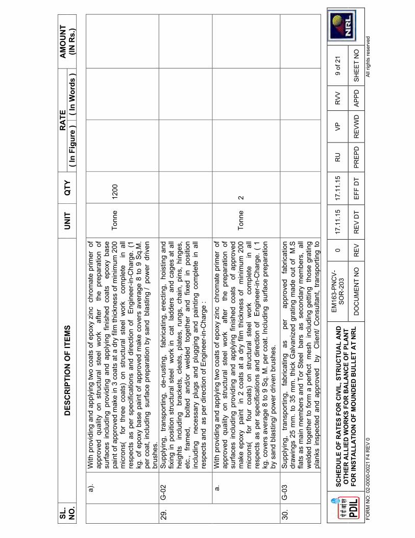
SL.
NO
.D
ESC
RIP
TIO
N O
F IT
EMS
UN
IT
QTY
R
ATE
AM
OU
NT
(IN R
s.)
( In
Figu
re )
( In
Wor
ds )
�
SCH
EDU
LE O
F R
ATE
S FO
R C
IVIL
, STR
UC
TUA
L A
ND
O
THER
ALL
IED
WO
RK
S FO
R B
ALA
NC
E O
F PL
AN
T FO
R IN
STA
LLA
TIO
N O
F M
OU
ND
ED B
ULL
ET A
T N
RL
EM
163-
PN
CV
-S
OR
-203
0 17
.11.
15
17.1
1.15
R
U
VP
R
VV
9
of 2
1
DO
CU
ME
NT
NO
R
EV
R
EV
DT
EFF
DT
PR
EP
DR
EV
WD
A
PP
D
SH
EE
T N
O
FOR
M N
O: 0
2-00
00-0
021
F4 R
EV
0
All
right
s re
serv
ed�
a).
With
pro
vidi
ng a
nd a
pply
ing
two
coat
s of
epo
xy z
inc
chr
omat
e pr
imer
of
appr
oved
qua
lity
on s
truct
ural
ste
el w
ork
afte
r t
he p
repa
ratio
n of
su
rface
s in
clud
ing
prov
idin
g an
d ap
plyi
ng f
inis
hed
coat
s e
poxy
bas
e
pain
t of a
ppro
ved
mak
e in
3 c
oats
at a
dry
film
thic
knes
s of
min
imum
200
m
icro
ns(
for
thr
ee c
oats
) on
stru
ctur
al s
teel
wor
k c
ompl
ete
in
all
resp
ects
as
per
spec
ifica
tions
and
dire
ctio
n of
E
ngin
eer-
in-C
harg
e. (
1 kg
. of e
poxy
bas
e pa
int o
f app
rove
d m
ake
cove
rs a
vera
ge 8
to 9
Sq.
M.
per c
oat,
incl
udin
g s
urfa
ce p
repa
ratio
n by
san
d b
last
ing
/ po
wer
driv
en
brus
hes.
Tonn
e12
00
29.
G-0
2 S
uppl
ying
, tra
nspo
rting
, de
-rus
ting,
fa
bric
atin
g, e
rect
ing,
hoi
stin
g an
d fix
ing
in p
ositi
on s
truct
ural
ste
el
wor
k in
ca
t la
dder
s a
nd c
ages
at a
ll
heig
hts
inc
ludi
ng
brac
kets
, cl
eats
, pl
ates
, ru
ngs,
cha
in,
pins
, hi
nges
, et
c.,
fram
ed,
bo
lted
and/
or
wel
ded
toge
ther
an
d fix
ed
in
posi
tion
incl
udin
g n
eces
sary
plu
gs a
nd p
lugg
ing
and
pain
ting
com
plet
e in
all
resp
ects
and
as
per d
irect
ion
of E
ngin
eer-
in-C
harg
e :
a.
With
pro
vidi
ng a
nd a
pply
ing
two
coat
s of
epo
xy z
inc
chr
omat
e pr
imer
of
appr
oved
qua
lity
on s
truct
ural
ste
el w
ork
afte
r t
he p
repa
ratio
n of
su
rface
s in
clud
ing
prov
idin
g an
d ap
plyi
ng f
inis
hed
coat
s o
f ap
prov
ed
mak
e ep
oxy
pai
nt
in 2
coa
ts a
t a
dry
film
thi
ckne
ss o
f m
inim
um 2
00
mic
rons
( f
or f
our
coat
s) o
n st
ruct
ural
ste
el w
ork
com
plet
e i
n al
l re
spec
ts a
s pe
r sp
ecifi
catio
ns a
nd d
irect
ion
of
Eng
inee
r-in
-Cha
rge.
( 1
kg
. cov
ers
aver
age
8 to
9 S
q. M
. per
coa
t. In
clud
ing
sur
face
pre
para
tion
by s
and
blas
ting/
pow
er d
riven
bru
shes
.
Tonn
e2
30.
G-0
3 S
uppl
ying
, tra
nspo
rting
, fa
bric
atin
g as
per
ap
prov
ed
fabr
icat
ion
draw
ings
25
mm
. to
35 m
m. t
hick
Gal
vani
zed
grat
ing
mad
e ou
t of
M.S
fla
ts a
s m
ain
mem
bers
and
Tor
Ste
el b
ars
as
sec
onda
ry m
embe
rs,
all
wel
ded
toge
ther
to fo
rm a
per
fect
mes
h in
clud
ing
getti
ng t
hose
gra
ting
plan
ks in
spec
ted
and
appr
oved
by
C
lient
/ C
onsu
ltant
, tra
nspo
rting
to
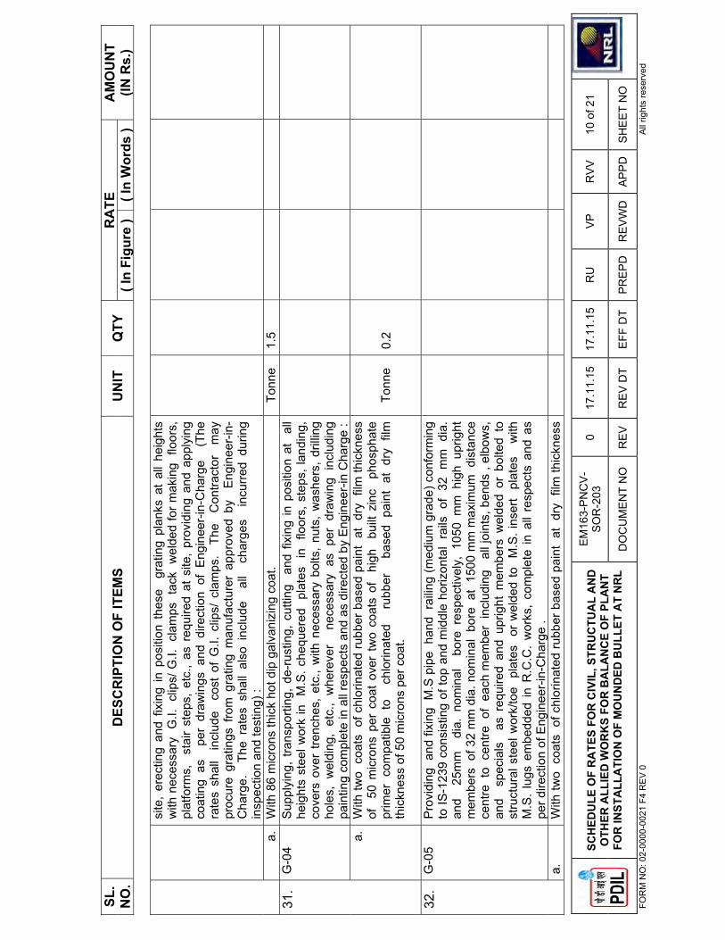
SL.
NO
.D
ESC
RIP
TIO
N O
F IT
EMS
UN
IT
QTY
R
ATE
AM
OU
NT
(IN R
s.)
( In
Figu
re )
( In
Wor
ds )
�
SCH
EDU
LE O
F R
ATE
S FO
R C
IVIL
, STR
UC
TUA
L A
ND
O
THER
ALL
IED
WO
RK
S FO
R B
ALA
NC
E O
F PL
AN
T FO
R IN
STA
LLA
TIO
N O
F M
OU
ND
ED B
ULL
ET A
T N
RL
EM
163-
PN
CV
-S
OR
-203
0 17
.11.
15
17.1
1.15
R
U
VP
R
VV
10
of 2
1
DO
CU
ME
NT
NO
R
EV
R
EV
DT
EFF
DT
PR
EP
DR
EV
WD
A
PP
D
SH
EE
T N
O
FOR
M N
O: 0
2-00
00-0
021
F4 R
EV
0
All
right
s re
serv
ed�
site
, er
ectin
g an
d fix
ing
in p
ositi
on t
hese
gr
atin
g pl
anks
at
all h
eigh
ts
with
nec
essa
ry G
.I. c
lips/
G.I.
cla
mps
tac
k w
elde
d fo
r mak
ing
floo
rs,
plat
form
s,
stai
r st
eps,
etc
., as
req
uire
d at
site
, pr
ovid
ing
and
appl
ying
co
atin
g as
pe
r dr
awin
gs a
nd d
irect
ion
of E
ngin
eer-
in-C
harg
e (
The
ra
tes
shal
l i
nclu
de
cost
of
G.I.
clip
s/ c
lam
ps.
The
C
ontra
ctor
m
ay
proc
ure
grat
ings
fro
m g
ratin
g m
anuf
actu
rer
appr
oved
by
Eng
inee
r-in
-C
harg
e.
The
rate
s sh
all
also
inc
lude
al
l c
harg
es
incu
rred
dur
ing
insp
ectio
n an
d te
stin
g) :
a.
With
86
mic
rons
thic
k ho
t dip
gal
vani
zing
coa
t.
Tonn
e 1.
5 31
.G
-04
Sup
plyi
ng,
trans
porti
ng,
de-r
ustin
g, c
uttin
g a
nd f
ixin
g in
pos
ition
at
all
heig
hts
stee
l wor
k in
M
.S. c
hequ
ered
pl
ates
in
flo
ors,
ste
ps, l
andi
ng,
cove
rs o
ver
trenc
hes,
etc
., w
ith n
eces
sary
bol
ts,
nuts
, w
ashe
rs,
drill
ing
hole
s, w
eldi
ng,
etc.
, w
here
ver
nec
essa
ry a
s pe
r dr
awin
g in
clud
ing
pain
ting
com
plet
e in
all
resp
ects
and
as
dire
cted
by
Eng
inee
r-in
Cha
rge
: a.
W
ith tw
o c
oats
of c
hlor
inat
ed ru
bber
bas
ed p
aint
at
dry
film
thic
knes
s
of
50 m
icro
ns p
er c
oat
over
tw
o co
ats
of
high
bu
ilt z
inc
pho
spha
te
prim
er c
ompa
tible
to
chl
orin
ated
ru
bber
ba
sed
pain
t at
dry
film
th
ickn
ess
of 5
0 m
icro
ns p
er c
oat.
Tonn
e0.
2
32.
G-0
5 P
rovi
ding
and
fixi
ng M
.S p
ipe
han
d ra
iling
(med
ium
gra
de) c
onfo
rmin
g to
IS-1
239
cons
istin
g of
top
and
mid
dle
horiz
onta
l ra
ils o
f 32
mm
dia
. an
d 2
5mm
di
a. n
omin
al
bore
res
pect
ivel
y, 1
050
mm
hig
h up
right
m
embe
rs o
f 32
mm
dia
. nom
inal
bor
e a
t 15
00 m
m m
axim
um d
ista
nce
ce
ntre
to
cen
tre o
f ea
ch m
embe
r in
clud
ing
all
join
ts, b
ends
, el
bow
s,
and
spe
cial
s a
s re
quire
d an
d up
right
mem
bers
wel
ded
or b
olte
d to
st
ruct
ural
ste
el w
ork/
toe
pla
tes
or
wel
ded
to
M.S
. ins
ert
plat
es
with
M
.S.
lugs
em
bedd
ed in
R.C
.C.
wor
ks,
com
plet
e in
all
resp
ects
and
as
per d
irect
ion
of E
ngin
eer-
in-C
harg
e .
a.
W
ith tw
o c
oats
of c
hlor
inat
ed ru
bber
bas
ed p
aint
at
dry
film
thic
knes
s

SL.
NO
.D
ESC
RIP
TIO
N O
F IT
EMS
UN
IT
QTY
R
ATE
AM
OU
NT
(IN R
s.)
( In
Figu
re )
( In
Wor
ds )
�
SCH
EDU
LE O
F R
ATE
S FO
R C
IVIL
, STR
UC
TUA
L A
ND
O
THER
ALL
IED
WO
RK
S FO
R B
ALA
NC
E O
F PL
AN
T FO
R IN
STA
LLA
TIO
N O
F M
OU
ND
ED B
ULL
ET A
T N
RL
EM
163-
PN
CV
-S
OR
-203
0 17
.11.
15
17.1
1.15
R
U
VP
R
VV
11
of 2
1
DO
CU
ME
NT
NO
R
EV
R
EV
DT
EFF
DT
PR
EP
DR
EV
WD
A
PP
D
SH
EE
T N
O
FOR
M N
O: 0
2-00
00-0
021
F4 R
EV
0
All
right
s re
serv
ed�
of
40 m
icro
ns p
er c
oat
over
tw
o co
ats
of
high
bu
ilt z
inc
pho
spha
te
prim
er c
ompa
tible
to
chl
orin
ated
ru
bber
ba
sed
pain
t at
dry
film
th
ickn
ess
of 2
5 m
icro
ns p
er c
oat.
Tonn
e1.
5
H.
ALU
MIN
IUM
DO
OR
S, W
IND
OW
S A
ND
VEN
TILA
TOR
S :
33.
H-0
1 P
rovi
ding
an
d f
ixin
g in
po
sitio
n a
t a
ll h
eigh
ts a
nodi
sed
alum
iniu
m
glaz
ed d
oors
and
gla
zing
of a
ppro
ved
sta
ndar
d tu
bula
r se
ctio
ns (
3 m
m
thic
k x
101.
5 x
44.5
mm
siz
e an
odis
ed w
ith 2
0 m
icro
n) in
clud
ing
fixin
g w
ith 1
6 x
3.15
mm
lugs
x
10 c
m lo
ng e
mbe
dded
in c
emen
t co
ncre
te
bloc
ks 1
5 cm
x 1
0 cm
x
10 c
m s
ize
of c
oncr
ete
nom
inal
mix
1:3
:6 (
1 ce
men
t: 3
coar
se s
and:
6 g
rade
d s
tone
agg
rega
te 2
0 m
m n
omin
al s
ize)
or
with
woo
den
plu
gs a
nd
scre
ws,
or
with
raw
al p
lugs
and
scr
ews
or
with
fix
ing
clip
s or
w
ith b
olts
and
nut
s or
fra
mes
fix
ed t
o a
djoi
ning
st
ruct
ural
ste
el m
embe
rs a
s pe
r de
sign
and
as
requ
ired,
inc
ludi
ng
prov
idin
g an
d fi
5
.5
mm
to
ughe
ned
glas
s
pane
s
with
sn
ap
on
anod
ised
alu
min
ium
be
adin
g a
nd P
VC
gas
ket
of a
ppro
ved
mak
e
with
m
atch
ing
scr
ews,
pr
ovid
ing
alu
min
ium
or
alu
min
ium
al
loy
fixtu
res
such
as
hing
es,
conc
eale
d bo
lts,
bas
e-tie
, l
ock
strik
e, l
ock
oper
able
fro
m i
nsid
e or
ou
tsid
e,
kiki
ng
plat
e a
t bo
ttom
, ha
ndle
s,
rubb
er b
uffe
rs,
etc.
, ap
plyi
ng a
co
at o
f l
acqu
er,
com
plet
e i
n a
ll re
spec
ts a
s p
er d
irect
ion
of E
ngin
eer-
in-C
harg
e (T
he r
ates
sha
ll b
e
incl
usiv
e o
f ce
men
t con
cret
e b
lock
s.
Ano
dise
d al
umin
ium
doo
rs m
ay
be o
f app
rove
d m
anuf
actu
rer
such
as
Ajit
Indi
a/ E
CIE
/ Al K
arm
a m
ake
or
its
app
rove
d eq
uiva
lent
).
Sqm
10
34.
H-0
2 P
rovi
ding
and
fix
ing
in p
ositi
on a
t al
l he
ight
s hy
drau
lic f
loor
spr
ings
w
ith d
oubl
e ac
tion
of E
CIE
or
Eve
rite
mak
e o
r eq
uiva
lent
I.S
.I. m
arke
d ap
prov
ed i
nclu
ding
fou
ndat
ion
box,
etc
. com
plet
e.E
ach
4
35.
H-0
3 P
rovi
ding
and
fix
ing
fully
gla
zed
anod
ised
al
umin
ium
win
dow
s an
d

SL.
NO
.D
ESC
RIP
TIO
N O
F IT
EMS
UN
IT
QTY
R
ATE
AM
OU
NT
(IN R
s.)
( In
Figu
re )
( In
Wor
ds )
�
SCH
EDU
LE O
F R
ATE
S FO
R C
IVIL
, STR
UC
TUA
L A
ND
O
THER
ALL
IED
WO
RK
S FO
R B
ALA
NC
E O
F PL
AN
T FO
R IN
STA
LLA
TIO
N O
F M
OU
ND
ED B
ULL
ET A
T N
RL
EM
163-
PN
CV
-S
OR
-203
0 17
.11.
15
17.1
1.15
R
U
VP
R
VV
12
of 2
1
DO
CU
ME
NT
NO
R
EV
R
EV
DT
EFF
DT
PR
EP
DR
EV
WD
A
PP
D
SH
EE
T N
O
FOR
M N
O: 0
2-00
00-0
021
F4 R
EV
0
All
right
s re
serv
ed�
vent
ilato
rs,
open
able
or
partl
y op
enab
le
of e
xtru
ded
hollo
w t
ubul
ar
sect
ions
sta
ndar
d IN
DA
L/H
IND
ALC
O/J
IND
AL
sect
ions
as
giv
en b
elow
, jo
ints
mitr
ed a
nd jo
inte
d w
ith a
lum
iniu
m
c
orne
r cl
eats
and
scr
ews
to m
atch
th
e s
ectio
n o
f fra
mes
in
clud
ing
pro
vidi
ng
and
fixi
ng
4mm
th
ick
plai
n s
heet
gla
ss c
onfo
rmin
g to
IS
:176
1, a
nodi
sing
sha
ll b
e 2
0 m
icro
ns o
f na
tura
l al
umin
ium
sh
ade
as
app
rove
d w
ith
snap
fit
alum
iniu
m b
eadi
ng a
nd h
igh
qua
lity
EP
DM
/NE
OP
RE
NE
wea
ther
pr
oof
gask
et
linin
g in
clud
ing
po
lysu
lphi
de
sea
lant
fi
lled
be
twee
n al
umin
ium
tu
be f
ram
e an
d w
all;
com
plet
e a
long
w
ith a
ll a
lum
iniu
m
fixtu
res
suc
h a
s h
andl
es,
proj
ecte
d hi
nges
, pe
g s
tays
, to
wer
bol
ts,
sprin
g ca
tch
all
com
plet
e a
s p
er d
raw
ings
and
tech
nica
l spe
cific
atio
n.S
EC
TIO
NS
TO
BE
US
ED
FO
R :-
Out
er fr
ame
- IN
DA
L 91
42 O
R E
quiv
alen
t of
HIN
DA
LCO
/JIN
DA
L S
hutte
r
-
IND
AL
9838
or E
quiv
alen
t
of H
IND
ALC
O/J
IND
AL
Mul
lion
- IN
DA
L 94
76 o
r Equ
ival
ent
of H
IND
ALC
O/J
IND
AL
Sna
p B
eadi
ng-
IND
AL
4122
,466
0 or
E
quiv
alen
t of
H
IND
ALC
O/
JIN
DA
L
��
(a)
Ope
nabl
e w
indo
ws
and
vent
ilato
rs (t
op h
ung
or c
entre
hun
g).
Sqm
10
(b)
Par
tly fi
xed
and
partl
y op
enab
le w
indo
ws
and
vent
ilato
rs.
Sqm
5
(c) F
ixed
type
win
dow
s an
d ve
ntila
tors
. S
qm
5 I.
RO
OFI
NG
: 36
I-1
Pro
vidi
ng a
nd f
ixin
g pr
e-co
ated
gal
vani
sed
iron
prof
ile s
heet
s (s
ize,
sh
ape
and
pitc
h of
cor
ruga
tion
as a
ppro
ved
by E
ngin
eer-
in-c
harg
e) 0
.50
mm
( +
0.05
%),
tota
l coa
ted
thic
knes
s w
ith z
inc
coat
ing
120
gm p
er s
qm
as p
er IS
:277
in 2
40 m
pa s
teel
gra
de, 5
-7 m
icro
ns e
poxy
prim
er o
n bo
th
side
of
the
shee
t an
d po
lyes
ter
top
coat
15-
18 m
icro
ns.
She
et s
houl
d ha
ve p
rote
ctiv
e gu
ard
film
of
25 m
icro
ns m
inim
um t
o av
oid
scra
tche
s
Sqm
40
0

SL.
NO
.D
ESC
RIP
TIO
N O
F IT
EMS
UN
IT
QTY
R
ATE
AM
OU
NT
(IN R
s.)
( In
Figu
re )
( In
Wor
ds )
�
SCH
EDU
LE O
F R
ATE
S FO
R C
IVIL
, STR
UC
TUA
L A
ND
O
THER
ALL
IED
WO
RK
S FO
R B
ALA
NC
E O
F PL
AN
T FO
R IN
STA
LLA
TIO
N O
F M
OU
ND
ED B
ULL
ET A
T N
RL
EM
163-
PN
CV
-S
OR
-203
0 17
.11.
15
17.1
1.15
R
U
VP
R
VV
13
of 2
1
DO
CU
ME
NT
NO
R
EV
R
EV
DT
EFF
DT
PR
EP
DR
EV
WD
A
PP
D
SH
EE
T N
O
FOR
M N
O: 0
2-00
00-0
021
F4 R
EV
0
All
right
s re
serv
ed�
durin
g tra
nspo
rtatio
n an
d sh
ould
be
supp
lied
in s
ingl
e le
ngth
upt
o 12
met
re o
r as
des
ired
by E
ngin
eer-
in-c
harg
e. T
he s
heet
sha
ll be
fix
ed
usin
g se
lf dr
illin
g /s
elf
tapp
ing
scre
ws
of s
ize
(5.5
x 55
mm
) w
ith E
PD
M
seal
, co
mpl
ete
up t
o an
y pi
tch
in h
oriz
onta
l/ ve
rtica
l or
curv
ed s
urfa
ces
excl
udin
g th
e co
st o
f pur
lins,
raf
ters
and
trus
ses
and
incl
udin
g cu
tting
to
size
and
sha
pe w
here
ver r
equi
red.
JW
ATE
R P
RO
OFI
NG
: 37
.J-
01
Pro
vidi
ng a
nd l
ayin
g in
situ
fiv
e co
urse
wat
er p
roof
ing
treat
men
t w
ith
AP
P (A
tact
ic P
olyp
ropy
lene
) mod
ified
Pol
ymer
ic m
embe
rane
ove
r roo
f co
nsis
ting
of fi
rst c
oat o
f bitu
men
prim
er @
0.4
0Kg
per s
qm, 2
nd &
4th
co
urse
s of
bon
ding
mat
eria
l @ 1
.20
kg/s
qm, w
hich
sha
ll co
nsis
t of b
low
n ty
pe b
itum
en o
f gra
de 8
5/25
con
form
ing
to IS
: 70
2, 3
rd la
yer
of r
oofin
g m
embr
ane
AP
P m
odifi
ed P
olym
eric
mem
bran
e 2.
0 m
m t
hick
of
3.00
K
g/sq
m w
eigh
t con
sist
ing
of fi
ve la
yers
pre
fabr
icat
ed w
ith c
entre
cor
e as
10
0 m
icro
n H
MH
DP
E fi
lm s
andw
iche
d on
bot
h si
des
with
pol
ymer
ic m
ix
and
the
poly
mer
ic m
ix is
pro
tect
ed o
n bo
th s
ide
with
20
mic
ron
HM
HD
PE
fil
m.
5th,
the
top
mos
t la
yer
shal
l be
fin
ishe
d w
ith b
rick
tiles
of
clas
s de
sign
atio
n 10
gro
uted
with
cem
ent m
orta
r 1:
3 (1
cem
ent :
3 fi
ne s
and)
m
ixed
with
2%
int
egra
l w
ater
pro
ofin
g co
mpo
und
by w
eigh
t of
cem
ent
over
a 1
2 m
m la
yer
of c
emen
t mor
tar
1:3
(1 c
emen
t : 3
fine
san
d) a
nd
finis
hed
neat
.
Sqm
� � � � �
100
K
FLO
OR
S A
ND
BA
SES
: 38
.K
-01
Sup
plyi
ng
and
layi
ng
hard
co
re
unde
r flo
ors
in
clud
ing
wat
erin
g,
ram
min
g,
bl
indi
ng
and
wel
l co
nsol
idat
ing
w
ith
br
oken
st
one
ag
greg
ates
90
mm
to
40 m
m i
n la
yers
of
max
imum
co
mpa
cted
th
ickn
ess
of 1
00 m
m in
clud
ing
fillin
g th
e vo
ids
with
sm
alle
r st
one
chi
ps
and
with
blin
ding
mat
eria
ls fi
ne ri
ver s
and.
(Pay
men
t sh
all
be m
ade
for
finis
hed
thic
knes
s of
har
d co
re) :

SL.
NO
.D
ESC
RIP
TIO
N O
F IT
EMS
UN
IT
QTY
R
ATE
AM
OU
NT
(IN R
s.)
( In
Figu
re )
( In
Wor
ds )
�
SCH
EDU
LE O
F R
ATE
S FO
R C
IVIL
, STR
UC
TUA
L A
ND
O
THER
ALL
IED
WO
RK
S FO
R B
ALA
NC
E O
F PL
AN
T FO
R IN
STA
LLA
TIO
N O
F M
OU
ND
ED B
ULL
ET A
T N
RL
EM
163-
PN
CV
-S
OR
-203
0 17
.11.
15
17.1
1.15
R
U
VP
R
VV
14
of 2
1
DO
CU
ME
NT
NO
R
EV
R
EV
DT
EFF
DT
PR
EP
DR
EV
WD
A
PP
D
SH
EE
T N
O
FOR
M N
O: 0
2-00
00-0
021
F4 R
EV
0
All
right
s re
serv
ed�
a.C
onso
lidat
ion
by ro
ad ro
ller
Cum
. 13
00
b.C
onso
lidat
ion
by h
and/
mec
hani
cal r
amm
ers
Cum
. 70
39.
K-0
2 P
rovi
ding
and
layi
ng I
PS
flo
orin
g in
flo
ors
of b
uild
ings
, sh
eds
etc
in 1
2 m
m c
emen
t pla
ster
(1
cem
ent:
3 C
oars
e sa
nd)
with
floa
ting
coat
of n
eat
cem
ent.
Sqm
225
L
FIN
ISH
ING
: N
ote:
Rat
e sh
ould
incl
ude
prov
isio
n of
Chi
cken
wire
mes
h 20
0 w
ide
at
the
junc
tion
of b
rick
and
RC
C a
t all
loca
tions
( in
side
and
out
side
) 40
. L-
01
Pro
vidi
ng a
t al
l he
ight
s 12
mm
thi
ck c
emen
t pl
aste
r o
n br
ick
wor
k,
expo
sed
su
rface
s of
R
CC
lin
tels
, b
eam
s,
etc.
, co
mpl
ete
in a
ll re
spec
ts a
nd a
s di
rect
ed w
ith c
emen
t pla
ster
mix
: a.
1:4:
2 (1
cem
ent:
4 co
arse
san
d: 2
fine
san
d).
Sqm
20
0
41.
L-02
P
rovi
ding
at
all h
eigh
ts 1
5 m
m t
hick
cem
ent
plas
ter
on
roug
h s
ide
of
sing
le o
r ha
lf br
ick
wal
ls, e
tc.,
com
plet
e in
al
l res
pect
s an
d as
dire
cted
w
ith c
emen
t pla
ster
mix
:
a.
1:4
(1 c
emen
t: 4
coar
se s
and)
. S
qm
200
42.
L-03
Pro
vidi
ng a
t al
l hei
ghts
6 m
m t
hick
cem
ent
plas
ter
1:2
:2 (
1cem
ent
: 2
co
arse
san
d : 2
fine
san
d) t
o c
eilin
g, e
tc.,
as
dire
cted
. S
qm10
0
43.
L-04
P
rovi
ding
and
app
lyin
g oi
l bou
nd w
asha
ble
dist
empe
r of
app
rove
d br
and
and
man
ufac
ture
and
of r
equi
red
shad
e an
d co
lour
to
giv
e a
even
sha
de
over
and
inc
ludi
ng a
pr
imin
g c
oat
with
di
stem
per
prim
er
and
ne
cess
ary
sur
face
pre
para
tion
as
dire
cted
.
Sqm
20
0

SL.
NO
.D
ESC
RIP
TIO
N O
F IT
EMS
UN
IT
QTY
R
ATE
AM
OU
NT
(IN R
s.)
( In
Figu
re )
( In
Wor
ds )
�
SCH
EDU
LE O
F R
ATE
S FO
R C
IVIL
, STR
UC
TUA
L A
ND
O
THER
ALL
IED
WO
RK
S FO
R B
ALA
NC
E O
F PL
AN
T FO
R IN
STA
LLA
TIO
N O
F M
OU
ND
ED B
ULL
ET A
T N
RL
EM
163-
PN
CV
-S
OR
-203
0 17
.11.
15
17.1
1.15
R
U
VP
R
VV
15
of 2
1
DO
CU
ME
NT
NO
R
EV
R
EV
DT
EFF
DT
PR
EP
DR
EV
WD
A
PP
D
SH
EE
T N
O
FOR
M N
O: 0
2-00
00-0
021
F4 R
EV
0
All
right
s re
serv
ed�
44.
L-05
P
rovi
ding
and
app
lyin
g on
e co
at o
f cem
ent
prim
er
of a
ppro
ved
bra
nd
and
man
ufac
ture
on
R.C
.C
surfa
ces,
in
clud
ing
nece
ssar
y su
rface
pr
epar
atio
n et
c. a
s di
rect
ed.
Sqm
.20
0
45.
L-06
P
aint
ing
(APE
X / W
eath
er c
oat /
Wea
ther
shi
eld)
Sup
plyi
ng a
nd a
pply
ing
3 co
ats
of A
pex
pain
t of A
sian
pai
nts
/ Wea
ther
co
at o
f B
erge
r pa
ints
/ W
eath
er s
hiel
d of
IC
I pa
ints
on
exte
rnal
wal
ls
surfa
ces
in a
ppro
ved
colo
ur a
t al
l he
ight
s as
per
sco
pe o
f w
ork
and
reco
mm
enda
tions
of m
anuf
actu
rer
incl
udin
g su
rface
pre
para
tion,
prim
er
putty
etc
. de
taile
d co
nstru
ctio
n dr
awin
gs,
tech
nica
l sp
ecifi
catio
ns a
nd
dire
ctio
ns o
f the
Eng
inee
r-In
-Cha
rge.
[R
ate
to i
nclu
de p
rimin
g co
at o
f pu
tty,
scaf
fold
ing,
too
ls &
tac
kles
co
nsum
able
s et
c]
Sqm
200
MSA
NIT
AR
Y W
OR
K
46
M-0
1 P
rovi
ding
and
fix
ing
was
h ba
sin
with
C.I.
bra
cket
s, 1
5 m
m C
.P.
bras
s pi
llar
taps
, 32
mm
C.P
. br
ass
was
te o
f st
anda
rd p
atte
rn,
incl
udin
g pa
intin
g of
fitt
ings
and
bra
cket
s, c
uttin
g an
d m
akin
g go
od t
he w
alls
w
here
ver r
equi
red:
W
hite
Vitr
eous
Chi
na W
ash
basi
n si
ze 6
30x4
50 m
m w
ith a
pai
r of
15
mm
C.P
. bra
ss p
illar
taps
Eac
h 1
47
M-0
2 P
rovi
ding
and
fix
ing
whi
te v
itreo
us c
hina
ped
esta
l ty
pe w
ater
clo
set
(Eur
opea
n ty
pe W
.C. p
an)
with
ISI m
arke
d w
hite
sol
id p
last
ic s
eat a
nd
lid,
10 li
tre lo
w le
vel w
hite
P.V
.C.
flush
ing
cist
ern,
incl
udin
g flu
sh p
ipe,
w
ith m
anua
lly c
ontro
lled
devi
ce (
hand
le le
ver)
, con
form
ing
to IS
: 72
31,
with
all
fittin
gs a
nd fi
xtur
es c
ompl
ete,
incl
udin
g cu
tting
and
mak
ing
good
th
e w
alls
and
floo
rs w
here
ver r
equi
red
Eac
h 1
48.
M-0
3 P
rovi
ding
and
fixi
ng m
irror
of s
uper
ior g
lass
(of a
ppro
ved
qual
ity) a
nd o
f re
quire
d sh
ape
and
size
with
pla
stic
mou
lded
fram
e of
app
rove
d m
ake
Eac
h 1

SL.
NO
.D
ESC
RIP
TIO
N O
F IT
EMS
UN
IT
QTY
R
ATE
AM
OU
NT
(IN R
s.)
( In
Figu
re )
( In
Wor
ds )
�
SCH
EDU
LE O
F R
ATE
S FO
R C
IVIL
, STR
UC
TUA
L A
ND
O
THER
ALL
IED
WO
RK
S FO
R B
ALA
NC
E O
F PL
AN
T FO
R IN
STA
LLA
TIO
N O
F M
OU
ND
ED B
ULL
ET A
T N
RL
EM
163-
PN
CV
-S
OR
-203
0 17
.11.
15
17.1
1.15
R
U
VP
R
VV
16
of 2
1
DO
CU
ME
NT
NO
R
EV
R
EV
DT
EFF
DT
PR
EP
DR
EV
WD
A
PP
D
SH
EE
T N
O
FOR
M N
O: 0
2-00
00-0
021
F4 R
EV
0
All
right
s re
serv
ed�
and
shad
e w
ith 6
mm
thic
k ha
rd b
oard
bac
king
:
Rec
tang
ular
sha
pe, s
ize
450
mm
x61
0 m
m
49
M-0
4 P
rovi
ding
and
fix
ing
whi
te v
itreo
us c
hina
fla
t ba
ck o
r w
all
corn
er t
ype
lippe
d fro
nt u
rinal
bas
in o
f 43
0x26
0x35
0 m
m a
nd 3
40x4
10x2
65 m
m
size
s re
spec
tivel
y w
ith 5
litr
e w
hite
aut
omat
ic f
lush
ing
cist
ern
with
st
anda
rd fl
ush
pipe
and
C.P
. bra
ss s
prea
ders
with
bra
ss u
nion
s an
d G
.I cl
amps
com
plet
e, in
clud
ing
pain
ting
of fi
tting
s an
d br
acke
ts, c
uttin
g an
d m
akin
g go
od th
e w
alls
and
floo
rs w
here
ver r
equi
red.
Eac
h 1
50
M-0
5 P
rovi
ding
and
fixi
ng 1
5 m
m d
ia P
VC
pip
es.
M
10
51
M-0
6 P
rovi
ding
and
fixi
ng tr
ap o
f sel
f cle
ansi
ng d
esig
n w
ith s
crew
ed d
own
or
hing
ed g
ratin
g w
ith o
r w
ithou
t ve
nt a
rm c
ompl
ete,
inc
ludi
ng c
ost
of
cutti
ng a
nd m
akin
g go
od t
he w
alls
and
flo
ors
(San
d ca
st ir
on S
&S
as
per I
S: 3
989)
Eac
h 3
52
M-0
7 P
rovi
ding
and
fixi
ng s
oil,
was
te a
nd v
ent p
ipes
(San
d ca
st ir
on S
&S
pip
e as
per
IS: 1
729)
(a)
100
mm
dia
M
10
(b
) 75
mm
dia
M
10
53
M-0
8 P
rovi
ding
and
fix
ing
C.P
. br
ass
bib
cock
(of
15
mm
nom
inal
bor
e) o
f ap
prov
ed q
ualit
y co
nfor
min
g to
IS:8
931
: E
ach
2
54
M-0
9 P
rovi
ding
and
fix
ing
C.P
. br
ass
stop
coc
k (c
once
aled
) of
sta
ndar
d de
sign
and
of a
ppro
ved
mak
e co
nfor
min
g to
IS:8
931.
E
ach
2
55
M-1
0 P
rovi
ding
and
fixi
ng C
.P. b
rass
ang
le v
alve
of a
ppro
ved
qual
ity (
15 m
m
nom
inal
bor
e)
Eac
h 2

SL.
NO
.D
ESC
RIP
TIO
N O
F IT
EMS
UN
IT
QTY
R
ATE
AM
OU
NT
(IN R
s.)
( In
Figu
re )
( In
Wor
ds )
�
SCH
EDU
LE O
F R
ATE
S FO
R C
IVIL
, STR
UC
TUA
L A
ND
O
THER
ALL
IED
WO
RK
S FO
R B
ALA
NC
E O
F PL
AN
T FO
R IN
STA
LLA
TIO
N O
F M
OU
ND
ED B
ULL
ET A
T N
RL
EM
163-
PN
CV
-S
OR
-203
0 17
.11.
15
17.1
1.15
R
U
VP
R
VV
17
of 2
1
DO
CU
ME
NT
NO
R
EV
R
EV
DT
EFF
DT
PR
EP
DR
EV
WD
A
PP
D
SH
EE
T N
O
FOR
M N
O: 0
2-00
00-0
021
F4 R
EV
0
All
right
s re
serv
ed�
NM
ISC
ELLA
NEO
US
: 56
.N
-01
Pro
vidi
ng a
nd fi
in p
ositi
on a
t all
hei
ghts
G.I.
pip
e fo
r cab
le e
ntry
in
RC
C/
cem
ent
conc
rete
/ br
ick
mas
onry
inc
ludi
ng m
akin
g go
od t
he w
all
etc.
Com
plet
e in
all
resp
ects
and
as
dire
cted
. (
All
mat
eria
ls a
re i
n co
ntra
ctor
’s s
cope
of s
uppl
y )
A.
G .I
. Pip
e
a.50
mm
dia
met
er.
Met
er
10
b.75
mm
dia
met
er.
M
eter
10
c.10
0 m
m d
iam
eter
.M
eter
10
d.15
0 m
m d
iam
eter
.M
eter
10
57.
N-0
2
Dem
olis
hing
of e
xist
ing
RC
C/P
CC
/Cem
ent C
oncr
ete
floor
/bou
lder
sol
ing
wor
k (in
clud
ing
cutti
ng
and
stac
king
of
st
eel
rein
forc
emen
ts)
and
disp
osal
of
unse
rvic
eabl
e m
ater
ials
fro
m s
ite o
f w
ork
to o
ther
are
a,
hand
ing
over
rei
nfor
cem
ents
to
the
Ow
ner's
/Con
sulta
nt's
sto
re a
t si
te,
com
plet
e
as
dire
cted
b
y
Eng
inee
r-in
-Cha
rge.
a)
. W
ithin
a le
ad o
f 50
met
res
Cum
10
58
N-0
3 D
ispo
sal
of
all
type
de
bris
of
di
sman
tled
item
s (P
CC
,RC
C,B
rick
wor
k,B
ould
er s
olin
g et
c.)
any
whe
re o
utsi
de fa
ctor
y / p
lant
bat
tery
lim
it,
com
plet
e as
d
irect
ed
by
E
ngin
eer-
in-C
harg
e.
beyo
nd in
itial
lead
of
50 m
upt
o 10
km
.
Cum
10
59.
N-0
4S
tripp
ing
the
conc
rete
of t
op p
ortio
n of
pile
from
the
strip
ping
leve
l to
the
cut-o
ff le
vel o
r as
dire
cted
. a)
Fo
r 450
dia
. Pile
M
etre
20

SL.
NO
.D
ESC
RIP
TIO
N O
F IT
EMS
UN
IT
QTY
R
ATE
AM
OU
NT
(IN R
s.)
( In
Figu
re )
( In
Wor
ds )
�
SCH
EDU
LE O
F R
ATE
S FO
R C
IVIL
, STR
UC
TUA
L A
ND
O
THER
ALL
IED
WO
RK
S FO
R B
ALA
NC
E O
F PL
AN
T FO
R IN
STA
LLA
TIO
N O
F M
OU
ND
ED B
ULL
ET A
T N
RL
EM
163-
PN
CV
-S
OR
-203
0 17
.11.
15
17.1
1.15
R
U
VP
R
VV
18
of 2
1
DO
CU
ME
NT
NO
R
EV
R
EV
DT
EFF
DT
PR
EP
DR
EV
WD
A
PP
D
SH
EE
T N
O
FOR
M N
O: 0
2-00
00-0
021
F4 R
EV
0
All
right
s re
serv
ed�
60.
� � � � �
N-0
5P
rovi
ding
and
fix
ing
rolli
ng s
hutte
rs o
f ap
prov
ed m
ake
mad
e of
80
mm
w
ide
MS
lath
s an
d in
terlo
cked
tog
ethe
r th
roug
h th
eir
entir
e le
ngth
and
jo
inte
d to
geth
er a
t the
end
s by
end
lock
s, m
ount
ed o
n sp
ecia
lly d
esig
ned
pipe
sha
ft w
ith b
rack
et p
late
s, g
uide
cha
nnel
s an
d ar
rang
emen
t fo
r in
side
and
out
side
loc
king
with
mec
hani
cally
gea
r op
erat
ed o
pera
tion
com
plet
e in
clud
ing
cost
of
wire
spr
ing
and
hood
cov
er f
or t
he s
hutte
rs,
(Mea
sure
men
t sha
ll be
don
e on
the
open
ing
only
).
Kg
400
RD
RO
AD
S�
Not
e :�
1.
The
Te
nder
er s
hall
note
tha
t th
e su
pply
of
man
pow
er,
arra
ngin
g pr
ecis
e in
stru
men
ts, c
uttin
g of
wild
bus
hes,
etc
. req
uire
d fo
r pro
per e
xecu
tion
of th
e w
ork,
sha
ll be
thei
r res
pons
ibilit
y.
��
��
�
��
��
��
��
�2.
The
Ten
dere
r sha
ll no
te th
at th
e su
pply
/ pr
ocur
emen
t of a
llth
e m
ater
ials
, req
uire
d fo
r the
job,
sha
ll be
thei
r res
pons
ibilit
y.
��
��
�
��
��
��
�61
�R
D –
01
Pre
para
tion
of S
ub B
ase
by e
xcav
atin
g ea
rth to
an
aver
age
of30
0 m
m d
epth
, dre
ssin
g to
cam
ber a
nd c
onso
lidat
ing
with
pow
erro
ad ro
ller i
nclu
ding
mak
ing
good
the
undu
latio
ns e
tc. a
nddi
spos
al o
f sur
plus
ear
th w
ithin
the
fact
ory
batte
ry li
mits
are
aco
mpl
ete
in a
ll re
spec
ts a
nd a
s di
rect
ed :
�� �
��
�
a). I
n S
oft /
Loo
se /
Har
d / D
ense
Soi
l S
q.M
2100
��
��
��
��
62R
D –
R
emov
al a
nd c
arria
ge o
f su
rplu
s ex
cava
ted
earth
, de
bris
, et
c.,
Cu.
M
625�
��
�

SL.
NO
.D
ESC
RIP
TIO
N O
F IT
EMS
UN
IT
QTY
R
ATE
AM
OU
NT
(IN R
s.)
( In
Figu
re )
( In
Wor
ds )
�
SCH
EDU
LE O
F R
ATE
S FO
R C
IVIL
, STR
UC
TUA
L A
ND
O
THER
ALL
IED
WO
RK
S FO
R B
ALA
NC
E O
F PL
AN
T FO
R IN
STA
LLA
TIO
N O
F M
OU
ND
ED B
ULL
ET A
T N
RL
EM
163-
PN
CV
-S
OR
-203
0 17
.11.
15
17.1
1.15
R
U
VP
R
VV
19
of 2
1
DO
CU
ME
NT
NO
R
EV
R
EV
DT
EFF
DT
PR
EP
DR
EV
WD
A
PP
D
SH
EE
T N
O
FOR
M N
O: 0
2-00
00-0
021
F4 R
EV
0
All
right
s re
serv
ed�
02m
anua
lly o
r m
echa
nica
lly in
clud
ing
load
ing,
unl
oadi
ng,
spre
adin
g an
d le
velin
g th
e sa
me
in l
ayer
s up
to
a le
ad o
f 50
0 M
bey
ond
fact
ory
batte
ry li
mits
are
a, c
ompl
ete
in a
ll re
spec
ts a
s pe
r dire
ctio
n of
Eng
inee
r-in
-Cha
rge.
�
��
�63
RD
- 03
Sam
e as
Ite
m N
o. R
- 0
2, b
ut f
or a
dditi
onal
lea
d of
1,0
00 M
be
yond
fact
ory
batte
ry li
mits
are
a.C
u.M
25�
��
�
��
��
64R
D -
04S
uppl
ying
, sta
ckin
g, la
ying
& r
ollin
g as
per
Tec
hnic
al S
peci
ficat
ion
to f
orm
sub
bas
e of
230
mm
thk
. In
tw
o la
yers
of
grad
ed s
tone
ag
greg
ates
at s
ite o
f siz
e ra
nges
90
mm
to 4
5 m
m
Cu.
M50
0��
��
�
��
��
65
RD
- 05
Layi
ng w
ater
bou
nd m
acad
am o
f 20
0 m
m t
hk.
in t
wo
laye
rs w
ith
spec
ified
sto
ne a
ggre
gate
s of
siz
e 63
mm
to 4
5 m
m to
form
bas
e ,
ston
e sc
reen
ings
and
blin
ding
mat
eria
l inc
ludi
ng s
uppl
y, s
tack
ing,
sc
reen
ing,
sor
ting,
spr
eadi
ng t
o te
mpl
ate
and
cons
olid
atio
n w
ith
pow
er ro
ad ro
ller o
f 8 to
10
Tonn
e ca
paci
ty e
tc. c
ompl
ete.
Cu.
M45
0��
��
�
��
�66
R
D -
06P
rovi
ding
and
lay
ing
50 m
m t
hick
bitu
min
ous
conc
rete
sur
face
co
urse
usi
ng m
iner
al a
ggre
gate
sat
isfy
ing
the
grad
atio
n se
t out
in
the
spec
ifica
tions
with
6%
bin
der
cont
ent 8
0 / 1
00 o
r eq
uiva
lent
(
By
wei
ght
of t
otal
mix
) w
ith t
he a
id o
f ho
t m
ix p
lant
and
pav
e in
clud
ing
rollin
g w
ith ro
ad ro
ller t
o ac
hiev
e th
e re
quire
d co
mpa
ctio
n an
d de
nsity
.
Cu.
M12
5��
��
�
��
�

SL.
NO
.D
ESC
RIP
TIO
N O
F IT
EMS
UN
IT
QTY
R
ATE
AM
OU
NT
(IN R
s.)
( In
Figu
re )
( In
Wor
ds )
�
SCH
EDU
LE O
F R
ATE
S FO
R C
IVIL
, STR
UC
TUA
L A
ND
O
THER
ALL
IED
WO
RK
S FO
R B
ALA
NC
E O
F PL
AN
T FO
R IN
STA
LLA
TIO
N O
F M
OU
ND
ED B
ULL
ET A
T N
RL
EM
163-
PN
CV
-S
OR
-203
0 17
.11.
15
17.1
1.15
R
U
VP
R
VV
20
of 2
1
DO
CU
ME
NT
NO
R
EV
R
EV
DT
EFF
DT
PR
EP
DR
EV
WD
A
PP
D
SH
EE
T N
O
FOR
M N
O: 0
2-00
00-0
021
F4 R
EV
0
All
right
s re
serv
ed�
67
RD
- 07
Pro
vidi
ng
and
layi
ng
25
mm
th
ick
com
pact
ed
prem
ix
carp
et
surfa
cing
with
3 C
u.M
of s
tone
chi
ppin
gs 1
0 m
m n
omin
al s
ize
per
100
Sq.
M a
nd 6
4 K
g. o
f bi
tum
en p
avin
g as
phal
t gra
de 8
0 / 1
00 o
f ap
prov
ed q
ualit
y pe
r Cu.
M o
f sto
ne c
hipp
ing
incl
udin
g a
tack
coa
t w
ith b
itum
en a
spha
lt gr
ade
80 /
100
of a
ppro
ved
qual
ity 1
Kg.
per
S
q.M
of
ro
ad
surfa
ce
and
cons
olid
atio
n w
ith
road
ro
ller
etc.
co
mpl
ete
in a
ll re
spec
ts a
nd a
s di
rect
ed.
Sq.
M21
00�
��
��
�
��
�68
R
D -
08P
rovi
ding
and
layi
ng 6
mm
sea
l coa
t of
pre
mix
ed f
ine
aggr
egat
e (p
assi
ng 2
.36
mm
and
ret
aine
d on
180
mic
ron
siev
e) u
sing
0.6
0 C
u.M
of f
ine
aggr
egat
epe
r 100
Sq.
M o
f roa
d su
rface
with
bitu
men
us
ing
128
Kg
of b
itum
en g
rade
80
/ 10
0 of
app
rove
d qu
ality
per
cu
m o
f fin
e ag
greg
ate
incl
udin
g ro
lling
and
finis
hing
with
road
rolle
r in
clud
ing
spre
adin
g dr
y cl
ean
coar
se s
and
@ 0
.6 c
u.m
/ 10
0 S
q.m
fo
r flu
shin
g ov
er t
he f
inal
sur
face
com
plet
e in
all
resp
ects
and
as
dire
cted
.
Sq.
M21
00�
��
�
�
��
�69
R
D -
09D
ress
ing
the
grou
nd &
fixi
ng o
f pav
ers
bloc
k fo
r be
rms
incl
udin
g ea
rthw
ork
in e
xcav
atio
n, w
ater
ing,
rol
ling
with
roa
d ro
ller
and
disp
osal
of
surp
lus
earth
with
in t
he f
acto
ry b
atte
ry l
imits
are
a co
mpl
ete
in a
ll re
spec
ts a
nd a
s di
rect
ed.
Sq.
M50
0��
��
�
��
�70
RD
- 10
Pro
vidi
ng a
nd la
ying
ker
b st
one
incl
udin
g ea
rthw
ork
in e
xcav
atio
n,
refil
ling
and
disp
osal
of
surp
lus
earth
with
in f
acto
ry b
atte
ry l
imit
area
com
plet
e in
all
resp
ects
and
as
dire
cted
.
Met
re36
0��
��

SL.
NO
.D
ESC
RIP
TIO
N O
F IT
EMS
UN
IT
QTY
R
ATE
AM
OU
NT
(IN R
s.)
( In
Figu
re )
( In
Wor
ds )
�
SCH
EDU
LE O
F R
ATE
S FO
R C
IVIL
, STR
UC
TUA
L A
ND
O
THER
ALL
IED
WO
RK
S FO
R B
ALA
NC
E O
F PL
AN
T FO
R IN
STA
LLA
TIO
N O
F M
OU
ND
ED B
ULL
ET A
T N
RL
EM
163-
PN
CV
-S
OR
-203
0 17
.11.
15
17.1
1.15
R
U
VP
R
VV
21
of 2
1
DO
CU
ME
NT
NO
R
EV
R
EV
DT
EFF
DT
PR
EP
DR
EV
WD
A
PP
D
SH
EE
T N
O
FOR
M N
O: 0
2-00
00-0
021
F4 R
EV
0
All
right
s re
serv
ed�
TOTA
L:-
Am
ount
in W
ords
: R
s……
……
……
……
……
……
……
……
……
……
……
….
Dis
coun
t
:
Rs…
……
……
……
……
……
……
……
……
……
……
……
.
Tota
l Am
ount
:
Rs…
……
……
……
……
……
……
……
……
……
……
……
.
Nam
e
:……
……
……
……
……
……
……
……
……
……
……
……
…
Sig
natu
re o
f Ten
dere
r :…
……
……
……
……
……
……
……
……
……
……
……
……
Pla
ce /
Dat
e
:…
……
……
……
……
……
……
……
……
……
……
……
……