ADVANCING SUBSTATION INFRASTRUCTURE - … SUBSTATION INFRASTRUCTURE - elp.com

Attachment Collector Substation
for
2021 Request for Proposals
for Build-Own-Transfer
Solar Photovoltaic Resources
Entergy Louisiana, LLC
March 10, 2021 DRAFT
CONFIDENTIAL

Table of Contents
1.0 Introduction .............................................................................................................................................. 4
1.1 Purpose ......................................................................................................................................................... 4
1.2 Scope ............................................................................................................................................................ 4
1.3 General Data ................................................................................................................................................ 4
1.4 HV Collector Substation Work .................................................................................................................... 5
1.5 Changes in this Revision .............................................................................................................................. 5
1.6 Deviations. . ................................................................................................................................................ 5
2.0 Definitions, Terminology and Acronyms ................................................................................................ 5
3.0 Applicable Codes and Standards ............................................................................................................. 7
4.0 Safety ....................................................................................................................................................... 8
5.0 General Requirements .............................................................................................................................. 8
5.1 Site Environmental Characteristics .............................................................................................................. 8
6.0 Substation Current, Voltages and Clearances .......................................................................................... 8
6.1 Current Ratings ............................................................................................................................................ 8
6.2 Voltage Ratings ............................................................................................................................................ 8
6.3 Clearances and Spacing ............................................................................................................................... 9
7.0 Substation Equipment ............................................................................................................................ 11
7.1 Approved Manufacturers ........................................................................................................................... 11
7.2 HV Cables .................................................................................................................................................. 11
7.3 Substation Bus/Conductors ........................................................................................................................ 11
7.4 Insulators .................................................................................................................................................... 11
7.5 Surge Arresters........................................................................................................................................... 12
7.6 Disconnect Switches .................................................................................................................................. 14
7.7 Line Tuners ................................................................................................................................................ 17
7.8 Metering Devices ....................................................................................................................................... 17
7.9 Circuit Breakers ......................................................................................................................................... 21
7.10 Generator Step-up Unit (GSU) / Main Power Transformer (MPT) ........................................................... 23
7.11 Neutral Grounding Reactor (NGR) ............................................................................................................ 36
7.12 Station Service Transformer (Auxiliary Loads) ........................................................................................ 36
7.13 Reactive Equipment ................................................................................................................................... 37
7.14 Control House ............................................................................................................................................ 38
8.0 Substation Civil/Structural Design Criteria ........................................................................................... 40
8.1 Siting and Civil .......................................................................................................................................... 40
8.2 Structures and Foundations ........................................................................................................................ 45
8.3 Fence & Signage ........................................................................................................................................ 60
9.0 Substation Physical Design Criteria....................................................................................................... 60
9.1 Substation Bus System ............................................................................................................................... 60
9.2 Grounding System ..................................................................................................................................... 62
9.3 Conduit System .......................................................................................................................................... 64
9.4 Lightning System ....................................................................................................................................... 65
9.5 Lighting System ......................................................................................................................................... 66
9.6 Substation Security/Safety (CODE) .......................................................................................................... 67
9.7 Animal Deterrents ...................................................................................................................................... 67

10.0 Substation Protection & Control Design Criteria .................................................................................. 68
10.1 Protection and Control Requirements ........................................................................................................ 68
10.2 Relay Calculations and Setting Requirements ........................................................................................... 71
10.3 Control House ............................................................................................................................................ 72
10.4 DC System ................................................................................................................................................. 73
10.5 AC System ................................................................................................................................................. 73
10.6 Metering Requirements .............................................................................................................................. 74
10.7 SCADA ...................................................................................................................................................... 74
10.8 Communications ........................................................................................................................................ 75
10.9 Digital Fault Recorder (DFR) .................................................................................................................... 75
10.10 Low Voltage Cable (Wiring)................................................................................................................... 76
11.0 Physical and Electronic Security ........................................................................................................... 76
12.0 Deliverables ........................................................................................................................................... 77
13.0 Attachments ........................................................................................................................................... 78
1. Attachment 1: Approved Manufacturer List* ........................................................................................ 78
2. Attachment 2: Site Environmental Characteristics ................................................................................ 78
Site Environmental Characteristics ...................................................................................................................... 85
1.0 Introduction
1.1 Purpose This Attachment to the Scope Book (“this Attachment”) provides design requirements and reference material for the design of renewable energy (solar, wind, battery storage) collector substations (the “Collector Substations”) that will be built in or connected to the Project. This Attachment is intended to provide to Seller and others acting at Seller’s request requirements, recommendations, and guidance in the planning, design, construction, asset management, use, and operation of the Collector Substations.
1.2 Scope This Attachment applies to all new Collector Substations. This Attachment primarily describes technical requirements, both performance-based and prescriptive for the design and installation of Collector Substations. Refer to the Scope Book and other parts of the Agreement for information regarding project sequencing and milestones, the project execution plan, project schedule and schedule management, project controls reporting, health and safety information, factory acceptance tests, training, required submittals, design reviews, equipment records, specified deliverables, project documentation, and other relevant matters not covered by this Attachment.
1.3 General Data1 This Attachment addresses aspects of the Work relating to Collector Substations. It is not intended to be, and shall not be construed to be, a comprehensive list of each and every element or other requirement applicable to the Work and shall in no way limit Seller’s obligations under the Agreement or any Ancillary Agreement. Without limiting the other terms of the Agreement or any Ancillary Agreement, in performing the Work relating to Collector Substations, Seller shall comply with, any cause its Contractors and Subcontractors to comply with, the terms of this Attachment, the Scope Book, all Laws (including codes) and applicable Permits, and the other elements of the Performance Standard. This Attachment provides the minimum functional specification (MFS) for the Collector Substations, including scope and design requirements. In addition to the requirements set forth in the Agreement (including the Scope Book), the Collector Substations shall comply with all requirements specified in the GIA or any other Required Deliverability Arrangement. This Attachment is part of the Scope Book.
Article, Section, Table, Figure, and Attachment references in this Attachment are to this Attachment unless otherwise provided or the context otherwise requires.
1 The document remains subject in all respects to Buyer’s continued due diligence and internal review (including by Buyer’s subject
matter experts). On occasion, this draft includes certain provisions on the basis that the drafters were unaware of information that might
cause those provisions to be drafted in a materially different way or eliminated altogether. This draft may need to be revised to reflect certain
matters included or not addressed in the Agreement or the RFP or that have been reconsidered. ELL reserves the right to issue an updated
version of this document at a later date.

1.4 HV Collector Substation Work The Work includes the supply, assembly, and installation of the following components:
• HV switchgear, if applicable
• MV switchgear, if applicable
• MV/HV transformer(s)
• Switchyard buses
• Revenue metering
• Circuit breakers
• Disconnect switches
• Overhead line
• Backup power supply/emergency generator
• UPS, if applicable
• HVAC
• Grounding
• Lightning protection system, if applicable
• Conduits and cable trays
• Cables
• Relay Protection
• Lighting systems (including emergency lighting)
• I&C system (including fire alarm system), if applicable
• Earthwork
• Structures
• Fencing
1.5 Changes in this Revision
• Document created. 01.20.2021
1.6 Deviations. Any deviations from the MFS for the Collector Substations or the terms of this Attachment shall require Buyer’s prior approval and will be subject to the terms of the Agreement.
2.0 Definitions, Terminology and Acronyms Terms with initial capital letters used but not defined in this document shall have the meanings ascribed to such terms in the Agreement, unless the context otherwise requires. For the avoidance of doubt, the rules of interpretation set forth in the main body of the Agreement shall apply to this document.

Equipment support structures: Generally, refers to all structures within the Collector Substation other than the control house. System Voltage: The root-mean-square (rms) phase-to-phase voltage of a portion of an alternating-current electric system. Each system voltage pertains to a portion of the system that is bounded by transformers or utilization equipment. (All voltages are rms phase to-phase or phase-to-neutral voltages.) (ANSI C84.1) Nominal System Voltage: The voltage by which a portion of the system is designated, and to which certain operating characteristics of the system are related. Each nominal system voltage pertains to a portion of the system bounded by transformers or utilization equipment. (ANSI C84.1) Maximum System Voltage: The highest system voltage that occurs under normal operating conditions, and the highest system voltage for which equipment and other components are designed for satisfactory continuous operation without derating of any kind. In defining maximum system voltage, voltage transients and temporary overvoltages caused by abnormal system conditions such as faults, load rejection, and the like are excluded. However, voltage transients and temporary overvoltages may affect equipment operating performance and are considered in equipment application. (ANSI C84.1) Low Voltage (LV): Nominal system voltage less than 1000 volts. This term is also used as an adjective to designate the low voltage winding of a power transformer and for referring to the low voltage side of a distribution substation. Medium Voltage (MV): Nominal system voltage above 1 kV and up to 38 kV. (Note that ANSI C84.1 defines medium voltage as nominal system voltage above 1 kV and below 100 kV). High Voltage (HV): Nominal system voltages 69 kV and higher up to 230 kV. (Note that ANSI C84.1 defines high voltage as nominal system voltage between 100 kV and 230 kV). This term is also used as an adjective to designate the high voltage winding of a power transformer and for referring to the high voltage side of a distribution substation. Extra High Voltage (EHV): Nominal system voltage 345 kV and above. Ampacity: The current-carrying capacity, expressed in amperes, of an electric conductor under stated thermal conditions. Distribution Substation: A substation whose combination of switching equipment and step- down power transformers are arranged to reduce incoming transmission and distribution voltages, from Transmission up to 230 kV, to Distribution at 34.5 kV and below, for distribution of power to rural, residential, commercial, and industrial loads. It may or may not contain transmission breakers. Distribution substations may also be a combination of switching equipment and step-down transformers arranged to reduce distribution voltages to lower distribution voltages. Switching Station: A substation that connects three or more transmission lines 69 kV or above without power transformers. A switching station does not serve distribution load.

Transmission Substation: A substation, 69 kV or above, containing switches, circuit breakers, busses, and transformers for switching power circuits and to transform power from one voltage to another or from one system to another. Note: the terms switching station and substation are commonly used as interchangeable. Finished Grade (or Subgrade): Design site elevation, after site grading. Substation Designer: For the purposes of this guide, any person, regardless of business unit or contractor or employment status, who makes decisions pertaining to the equipment to be used in a substation, or the manner in which it will be used. Generally, the term “Substation Designer” includes substation layout and relay designers. Base flood means the flood level having a one percent chance of being equaled or exceeded in any given year. Base flood is also known as 100-year flood. Note that a 100-year flood does not mean that such a flood occurs once every 100 years; instead, it means that there is a one in one-hundred (or 1%) chance of such a flood occurring in a given year. There is approximately a 63.4% chance of one or more 100-year floods occurring in any 100-year period.
3.0 Applicable Codes and Standards The Collector Substations shall be designed and constructed in accordance with all applicable and up to date codes, ordinances and standard industry practices including, without limitation, ANSI, IEEE, NEMA, standards and FERC, NERC and OSHA regulations. This includes, without limitation, the standards and guidelines for substation design established by the following sources:
• American National Standards Institute (ANSI)
• Institute of Electrical and Electronics Engineers (IEEE)
• Insulated Cable Engineers Association (ICEA)
• American Society of Mechanical Engineers (ASME)
• National Electrical Code (NEC)
• National Electrical Safety Code (NESC)
• National Electrical Manufacturers Association (NEMA)
• North American Electric Reliability Corporation (NERC)
• National Fire Protection Association (NFPA)
• Uniform Plumbing Code (UPC)
• Underwriters Laboratories (UL)
• American Concrete Institute (ACI)
• American Iron and Steel Institute (AISI)
• Federal Occupational Safety and Health Administration (OSHA)
• Avian Power Line Interaction Committee (APLIC)
• ANSI/TIA-568-C.0-2009 Generic Telecommunications Cabling for Customer Premises
• NECA/FOA 301-2009 Installing and Testing Fiber Optics
• RUS Bulletin 1724-200 Rural Utilities Service Design Manual for High Voltage Transmission Lines Electrical System Requirements

• RUS Bulletin 1724-300 Rural Utilities Service Design Guide for Rural Substations
• Underwriters Laboratories, Inc. (UL)
The latest issued Standards and Codes at the issuance of the effective date of the Agreement shall be used. Earlier editions are not allowed unless specifically identified in this Attachment. If a revision to a standard or code is issued, it is not required to be implemented unless the Authority Have Jurisdiction (AHJ) has adopted it, in which case, the Seller is obligated to any increased compliance above what is required by the Standards and Codes at the effective date of the Agreement. This risk is to be borne by the Seller.
4.0 Safety
The Substation Designer shall incorporate safe work practices into the design of the collector substation. The Collector Substations design and construction shall allow safe operation and maintenance under all foreseeable operating conditions. The design shall ensure that maintenance can be carried out without a significant effect on the Collector Substations operation and will allow adequate working space to maintain minimum approach distances as specified in the Section 6.3, Table 3.
Other aspects such as fire hazard and fire suppression and environmental aspects, such as site drainage and oil containment, shall be considered and incorporated in the design. The Substation Designer is responsible for ensuring that the Collector Substations are designed in compliance with the National Electrical Safety Code, OSHA, and other regulations. See Section 9.0for further details.
5.0 General Requirements
5.1 Site Environmental Characteristics In order to clarify the criteria to be used for the design of the Collector Substations, Seller shall determine the site environmental characteristics in “Attachment 2 Site Environmental Characteristics” and supply this information to Buyer with the bid. Additional pertinent criteria shall be provided as needed.
6.0 Substation Current, Voltages and Clearances
6.1 Current Ratings The Collector Substation bus systems, jumpers and equipment which is part of the bus shall be designed to serve the maximum equipment ratings. Equipment attached to buses, but not a part of the bus system, shall be designed to service the equipment maximum capabilities. Any current calculation performed shall take into consideration ambient temperature, temperature rise, conductor maximum operating temperature and coefficient of emissivity. Typical and acceptable ambient temperature value for continuous ampacity shall be 40°C. Size, variety, and types of conductors used in the Collector Substation shall be kept as minimal as practical.
6.2 Voltage Ratings The Collector Substation equipment and bus systems shall be designed for the voltage ratings in accordance with Table 1. Any project‐specific voltage requirements shall be considered, such as high voltage or contamination will dictate increased Basic Impulse levels (“BIL”) for a

specific design. This shall be coordinated and agreed upon by Seller and Buyer during project planning phases.
Table 1: Equipment Voltage Ratings
Nominal
Voltage
Rated
Voltage
BIL BSL Remarks
13.8 kV 15.5 kV 110 kV Bus, and Disconnects shall be rated 34.5 kV, 200
kV BIL
24 kV 25.8 kV 150 kV Bus, and Disconnects shall be rated 34.5 kV 200 kV BIL
34.5 kV 38 kV 200 kV
69 kV 72.5 kV 350 kV
115 kV 121 kV 550 kV Circuit breakers and instrument current
transformers shall be rated 145 kV and 650 kV BIL. 138 kV 145 kV 650 kV
161 kV 169 kV 750 kV
230 kV 242 kV 900 kV Instrument current transformers shall be rated 242
kV, and 1050 kV BIL 345 kV 362 kV 1300 kV 825 kV
500 kV 550 kV 1800 kV 1175 kV
6.3 Clearances and Spacing All Collector Substation equipment shall be designed to maintain minimum substation clearances and spacing in Table 2, Table 3, Table 4, and Table 5. The below clearances are the minimum allowable clearances for common collector substation HV and MV voltages. Values listed are for altitudes of 1000 meters (3300 feet) or less. See IEEE 1427 for altitude adjustments (if required).
Table 2: Substation Minimum Clearances
Minimum electrical clearances between the conductors, and conductors to ground, shall be as tabulated below.
Nominal Voltage
BIL (BSL) Minimum Clearance to Ground for Rigid Parts,
Minimum Clearance Between Phases (or Live Parts) for Rigid Parts,
Metal to Metal
7.5 kV 95 kV 7 inches 8 inches
15 kV 110 kV 8 inches 9 inches
25 kV 150 kV 11 inches 12 inches
34.5 kV 200 kV 15 inches 16 inches
69 kV 350 kV 26 inches 29 inches
115 kV 550 kV 41 inches 45 inches
138 kV 650 kV 49 inches 54 inches
161 kV 750 kV 56 inches 62 inches

230 kV 900 kV 67 inches 74 inches
345 kV 1300 (975) kV 97 (100) inches 105 (140) inches
500 kV 1800 (1300) kV 135 (150) inches 150 (215) inches
Table 3: Substation Minimum Safety Clearances
Minimum horizontal and vertical clearances to live parts for worker safety shall be as tabulated below. These clearances are intended to prevent unintentional encroachment by a worker into the guard zone.
Nominal Voltage
BIL (BSL) Vertical Clearance
Horizontal Clearance
7.5 kV 95 kV 8 ft 10 in 3 ft 4 in
15 kV 110 kV 9 ft 3 ft 6 in
25 kV 150 kV 9 ft 3 in 3 ft 9 in
34.5 kV 200 kV 9 ft 6 in 4 ft
69 kV 350 kV 10 ft 5 in 4 ft 11 in
115 kV 550 kV 11 ft 7 in 6 ft 1 in
138 kV 650 kV 12 ft 2 in 6 ft 8 in
161 kV 750 kV 12 ft 10 in 7 ft 4 in
230 kV 900 kV 13 ft 9 in 8 ft 3 in
345 kV 1300 (828) kV 18 ft 11 in 13 ft 5 in
500 kV 1800 (1167) kV 27 ft 21 ft 6 in
Table 4: Substation Minimum Vertical Clearances above Ground
Maximum System Voltage
Pedestrian Traffic
Roadways
7.5 kV 14 ft 6 in 18 ft 6 in
15 kV 14 ft 6 in 18 ft 6 in
25 kV 14 ft 6 in 18 ft 6 in
38 kV 14 ft 6 in 18 ft 6 in
72.5 kV 15 ft 2 in 19 ft 2 in
121 kV 16 ft 1 in 20 ft 1 in
145 kV 16 ft 7 in 20 ft 7 in
169 kV 17 ft 21 ft
245 kV 18 ft 6 in 22 ft 6 in
362 kV 20 ft 9 in 24 ft 9 in
550 kV 24 ft 4 in 28 ft 4 in
Note: These clearances shall be maintained under the maximum conductor operating temperatures

Table 5: Substation Minimum Horizontal Clearance to Fence
Nominal Voltage
BIL Clearance to Fence
7.5 kV 95 kV 10 ft
15 kV 110 kV 10 ft 1 in
25 kV 150 kV 10 ft 4 in
34.5 kV 200 kV 10 ft 7 in
69 kV 350 kV 11 ft 7 in
115 kV 550 kV 13 ft
138 kV 650 kV 13 ft 8 in
161 kV 750 kV 14 ft 4 in
230 kV 900 kV 15 ft 5 in
345 kV 1300 kV 18 ft 4 in
500 kV 1800 kV 21 ft 6 in
7.0 Substation Equipment
7.1 Approved Manufacturers An Approved Manufacturer List is included in Attachment 1. The Approved Manufacturer List includes a column with applicable Entergy purchase specifications. Approved Manufacturers should already be familiar with the applicable Entergy specifications and be able to provide equipment conforming to these specifications. Seller shall procure items from manufacturers listed in the Approved Manufacturer List in accordance with the applicable Entergy purchase specification and in accordance with this specification.
7.2 HV Cables Seller shall comply with the requirements of the GIA for the design, manufacturing, installation, and testing of all HV cables.
7.3 Substation Bus/Conductors Cable connections between the tube bus and equipment shall be ACSR (aluminum conductor steel reinforced), AAAC (all aluminum alloy cable) or AAC (all aluminum cable). Bus connectors shall be aluminum alloy for aluminum-to-aluminum connections and tinned bronze for aluminum-to-copper connections. Hardware connectors shall be welded onto the cable or tube. Aeolian cable shall be installed in the switchyard tubing to limit bus vibration.
7.4 Insulators All insulators for the rigid bus system and disconnect switches shall be porcelain station post and shall be ANSI 70 gray in color. High strength or extra‐high strength insulators may be required based on detailed analysis. See Section 7.4.1. Polymer station post insulators shall be used for jumper standoff support. Insulators shall conform to ANSI C29 standards. Insulators shall be specified to satisfy mechanical and electrical requirements including creepage based on the project contamination criteria. If contamination criteria is not available, medium (35mm/kV) shall be used.

Insulator Strength The determination of the required cantilever strength of the insulator shall be performed in accordance with ANSI/IEEE Standard 605. The determination of the required effective bus span length due to insulator strength shall be determined for the insulator chosen and the external forces applied.
Load Combinations: Case 1 – Extreme Wind: 2.5 D + 2.5 W IFW + 1.0 SC Case 2 – Ice with Concurrent Wind: 2.5 D + 2.5 IWIFI + 2.5 WIIFI + 1.0 SC Case 3 – Seismic: 2.5 D + 2.5 E (or EFS)IFE + 1.0 SC
Refer to ASCE 113 for definitions of the load components within the load cases above. Design values for these load cases shall be as defined in Section 8.2.2.1. IEEE 605-2008 recommends a safety factor of 0.4 be applied to insulator strengths for loads other than short circuit loading and 1.0 for short circuit loading. As detailed in IEEE 605-2008, Section 12.4.2, when different load types are combined, the loads must be calibrated by the appropriate safety factor. As such, the 2.5 Load Factors on loads other than short circuit loading shown above are used to account for the safety factor on the insulator strength.
7.5 Surge Arresters The surge arresters shall be station class, metal‐oxide (MOV) type. Surge arresters shall be in accordance with ANSI‐C62.11. The arrester housing shall be made of polymeric silicone and shall be gray in color. Arresters up to a rated duty cycle voltage of 60 kV shall be of single unit construction, and not more than 2 pieces up through 120 kV. Arresters shall not be used as rigid bus supports. Arresters shall be installed on all incoming line terminals and at transformer terminals. Arresters shall be installed as close as possible to the equipment being protected. Ratings for surge arresters shall be as shown in Table 6 and dimensions shall be as shown in Table 7. Table 6: Station Class Surge Arrester Ratings
Nominal System Voltage
(kV)
System Type
Rated Duty-Cycle
Voltage (kV)
Rated MCOV
(kV)
2.4
Effectively Grounded, wye connected system 3 2.55
Ungrounded or Impedance Grounded, Delta connected system
3 2.55
Distribution Networks (Note) 3 2.55
4.16
Effectively Grounded, wye connected system 6 5.1
Ungrounded or Impedance Grounded, Delta connected system
6 5.1
Distribution Networks (Note) 9 7.65
12.47-14.4 Effectively Grounded, wye connected system 12 10.2

Ungrounded or Impedance Grounded, Delta connected system
18 15.3
Distribution Networks (Note) 21 17
23
Effectively Grounded, wye connected system 21 17 Ungrounded or Impedance Grounded, Delta connected system
36 29
Distribution Networks (Note) 36 29
34.5
Effectively Grounded, wye connected system 30 24.4
Ungrounded or Impedance Grounded, Delta connected system
48 39
Distribution Networks (Note) 48 39
69 Effectively Grounded, wye connected system 60 48
115 Effectively Grounded, wye connected system 96 76
138 Effectively Grounded, wye connected system 120 98
161 Effectively Grounded, wye connected system 132 106
230 Effectively Grounded, wye connected system 192 152
345 Effectively Grounded, wye connected system 276 220
500 Effectively Grounded, wye connected system 420 335
Note: Ungrounded Distribution Network and Systems where an accidental ground can exist for
long periods of time.
Table 7: Arrester Housing Dimensions by Rating
Rated Duty- Cycle
Voltage
Creepage Distance
Height
3 kV 15” 8”
6 kV 20” 10”
12 kV 25” 13”
18 kV 34” 14”
21 kV 38” 16”
30 kV 45” 19”
36 kV 55” 23”
48 kV 55” 23”
60 kV 69” 25”
96 kV 115” 45”
120 kV 138” 50”
132 kV 161” 65”
192 kV 230” 92”
276 kV 345” 110”

420 kV 500” 175”
7.6 Disconnect Switches GSU high-side main disconnect switches are not required when there is only a single transformer configuration. The HV line disconnect shall provide isolation to HV circuit breaker and transformer without compromising safety or operations. When a dual transformer configuration is in place, the high side transformer circuit breaker shall include disconnect switches. The GSU shall include a low side disconnect switch to allow isolation of the entire transformer zone without the need of opening feeder circuit breaker hooksticks. The disconnect switches shall be three‐pole, group operated, single‐throw complete with station post insulators, switch blades, contacts, operating mechanisms and include all necessary hardware for the assembly and mounting to steel structures. All disconnect switches shall conform to IEEE Standard C37.30.1 for HV switches. Ratings for disconnect switches shall be as shown in Table 8 and Table 9. Standard practice is to orient the vertical and side break switches so that the blade shall be dead when the switch is in the open position, i.e. the hinge shall be towards the closest circuit breaker. All disconnect switches shall be provided with arcing horns which will interrupt charging or magnetizing currents to prevent any arcing at the main switch contacts. Grounding switches will be required for HV line disconnect switches. The line disconnect switch and associated ground switch shall be mechanically interlocked to avoid mis-operation, i.e. closing the line disconnect switch when the ground switch is closed and vice versa.
Table 8: HV Disconnect Switch Ratings
Nominal Operating
Voltage (phase‐to‐
phase)
230kV 161 kV 138kV 115kV 69kV 34.5 kV
Maximum Voltage
(phase‐to‐phase) See Table 1
Basic Impulse Level
(BIL)
Maximum Continuous
Current (amperes)
To be determined after study results
Short Time Withstand
(symmetrical) Current
To be determined after study results
Preferred
Configuration Type
Vertical Break/ Double End Break/ Center
Break
Vertical Break/
Double End
Break/ Center
Break
Vertical Break/
Center Break/
Hookstick

Table 9: EHV Disconnect Switch Ratings
Nominal Operating Voltage (phase‐to‐ phase) 345kV 500kV
Rated Voltage 362 kV 550 kV
Lightning Impulse Withstand Voltage 1300 kV 1800 kV
Switching Impulse Withstand Voltage 885 kV to ground
1120 kV across open gap
1150 kV to ground
1450 kV across open gap
Rated Continuous Current: 2000 A, or 3000 A
(To be determined after study
results)
2000 A, or 3000 A
(To be determined after study
results)
Rated Short Time Withstand 63 kA rms, 164 kA peak 63 kA rms, 164 kA peak
Short-time Current Withstand
Duration
3 seconds 3 seconds
Motor operated switches shall be monitored by the RTU or SCADA system. All disconnect switches whether motorized or not will have auxiliary contacts for system monitoring. Auxiliary contacts on motorized switches will not be actuated by the motor cam but will be triggered based on the physical switch position. Electrical interlocks shall be installed to prevent opening of motor operated disconnects and/or grounding switches when the station main breaker is in the closed position. The complete switch assembly shall have a rated ice breaking ability to open and close with a ¾” thick coating of ice. Gradient control rings shall be provided for switches at 230kV and higher voltages on both the hinge end and the jaw end to fully shield the live mechanism parts including the terminal pads. Flexible braids are not acceptable as by-pass shunts. Flexible laminated current carrying components are acceptable only when welded connections are made on each end. Bolted connections are not acceptable on laminated components. All moving contact surfaces for current transfer shall be silver or silver alloy. Aluminum or plated aluminum is not acceptable. The switches shall be free of visible corona at 110% rated voltage. The Radio Influence Voltage (RIV) shall not exceed 300 microvolts. All fastenings, nuts, bolts and washers utilized in the non-live parts area shall be of hot-dipped galvanized steel. Plated fastenings are not acceptable. All bearings shall be heavy duty with stainless steel balls and races. Aluminum or its alloys are not acceptable as a material for bearing raceways or bushing surfaces. Bearings shall be maintenance free and not located in the current carrying path. Switch bearings shall be lubricated and sealed and shall not require further field lubrication. Dry type, non-lubricated type bearings will be preferred. Lubricant shall be non-deteriorating with a projected shelf life in excess of ten years. All bearing assemblies shall be weatherproofed with

corrosion-free seals. All switches supplied with manual operating mechanism shall be readily convertible to motor operation. Maintenance ground studs shall be supplied on both hinge and jaw sides of the switch for attachment of portable ground cables. Design of the ground stud attachment shall be such that presence or absence of the ground studs will not change the switch height from its base to the top of the switch terminal pads. Ground studs shall be capable of being added to a switch in the field without undue switch dismantling. The ground studs shall be corona free, and shall be fully shielded where necessary. The ground studs material shall be the same as that of the switch contacts. The ground stud length shall be at least 6” for attaching the portable ground cable clamps, and have sufficient strength to support a 50 feet length of a 4/0 copper portable ground cable.
Operating Mechanism Hookstick operated switches may be used for equipment or circuit isolation, and regulator bypass applications up to 34.5 kV. Hookstick operated disconnect shall be located to provide switch operator space to allow 45 degree switch stick angle, for opening or closing, without operator or switch stick bumping into adjacent equipment, structures or foundations. Escape paths shall be considered in layout to deal with arcing or equipment failure that might occur during switching any switch or local breaker operation. Switches shall be supplied with a manual three-phase group operated mechanism. The operating mechanism shall be designed such that the complete three phase switch assembly can be operated to full open and closed positions by one person with a force of not more than 35 lbs applied to the actuating handle. The vertical operating pipe operation for switches up to and including 145 kV shall be torsion operated by a swing handle. The swing handle shall be galvanized steel pipe not less than 3 feet in length. The switch design, where operation with a swing handle would require a force greater than 35 lbs, shall utilize a worm gear operator. The vertical operating pipe operation for 170 kV and 230 kV switches shall be torsional operated by a worm gear in lieu of swing handle. For 363 kV and 550 kV switches, the switch shall be supplied preferably with a three-phase torsional gear drive mechanism with a gearbox for each pole. The operating mechanism shall be designed such that the complete three-phase switch assembly, can be operated to full open and closed positions with a force of not more than 35 lbs. applied to a manual actuating handle. The worm gear operator, when supplied, shall be in a sealed housing, corrosion and maintenance free. The gear operator shall be self-locking and prevent back driving of the crank handle during operation. The operating crank handle shall be no more than 15 inches in length. Status indication of operator position is not required for manually operated switches, but is required for motor operated switches.
EHV Switches (345 kV & 500 kV) Additional Requirements The mounting location for the switch operating handle and/or the motor operator shall be the

center pole support column. The switch shall use porcelain station post insulators ANSI TR number 368, rated 1300 kV BIL for 362 kV switches and ANSI TR number 391, rated 1800 kV BIL for 550 kV switches.
7.7 Line Tuners Communication using carrier equipment (line traps and tuners) shall not be used.
7.8 Metering Devices
General Metering systems for the Project shall be designed and installed to monitor and record all energy traveling to and from the Project and to permit the evaluation of the functionality and efficiency of the overall Project. Shorting-type terminal blocks shall be provided for all current transformer circuits to allow meters to be removed without disrupting current transformer circuits. A set of metering current transformers on the GSU secondary shall be provided. Potential transformers shall be provided on the medium voltage buses for input to the meters. Shorting-type terminal blocks shall be provided to allow meters to be removed without disturbing current transformer circuits. All permanently installed electrical metering instrumentation, or a combination of temporary test and permanently installed instrumentation, that will be used for the Project Performance Tests shall comply with maximum allowable measurement uncertainties per ASME PTC 22. Except where more restrictive requirements apply, relaying class accuracy voltage and current transformers are acceptable for panel indication meter applications. ABB FT-1 type test switches shall be provided for the voltage and current inputs to each meter.
Revenue Metering The revenue metering system shall be included in the Work except for installation of the revenue meters, which shall be performed by Buyer. Seller shall purchase the revenue meter(s) from ELL Transmission during the design phase of the Project. Notwithstanding anything herein to the contrary, all revenue meters, installation and purchases thereof, and revenue metering shall be in accordance with the GIA or other applicable Required Deliverability Arrangement (to the extent applicable) and the other elements of the Performance Standard. All meters shall conform to ANSI Standards C12.20, C12.1, and C12.10. Seller shall provide and install high accuracy 0.15B1.8 extended range CTs and 0.15Z accuracy PTs for GSU high-side revenue metering. Seller shall provide the revenue meter cabinet(s) to Buyer’s specifications. Seller shall design and install all wiring needed for revenue metering. Buyer shall install the revenue meters and make the final connections to the meters. Seller’s schedule for the Work shall allow a reasonable period of time for Buyer to undertake, complete, and test such installation and final connections, and Seller shall use commercially reasonable efforts to cooperate with Buyer in connection with such installation and final connections.

Metering Locations Other than where included with standard equipment packages (e.g., inverters), indication metering shall be provided in the following locations:
• High side of each GSU (voltage, current, kW, and kVAR)
• Each medium voltage main breaker (voltage, current, kW, and kVAR)
CCVT’s & PT’s Voltage transformers and/or CCVTs are required to provide a low voltage supply to protective relays and metering equipment. Voltage transformers, CVTs and CCVTs are directly connected to the high voltage bus. Fuses shall not be used on the high side of the Voltage Transformer. Auxiliary transformers are not permitted. Refer to Table 10 and Table 11 for required CCVT and PT ratings, respectively.
Table 10: CCVT Ratings
Nominal
System
Voltage
Maximum
Line to
Ground
Voltage
BIL Performance
Reference
Voltage
Nameplate
Ratio
Nameplate
Secondary
Voltage
Accuracy
69 kV 42 kV 350 kV 40.25 kV 350 / 600:1 115 / 67.1 Volts 0.6 WXYZ
115 kV 70 kV 550 kV 69 kV 600 / 1000:1 115 / 69 Volts 0.6 WXYZ
138 kV 84 kV 650 kV 80.5 kV 700 / 1200:1 115 / 67.1 Volts 0.6 WXYZ
161 kV 98 kV 750 kV 92 kV 800 / 1400:1 115 / 65.7 Volts 0.6 WXYZ
230 kV 140 kV 1050 kV 138 kV 1200 / 2000:1 115 / 69 Volts 0.3 WXYZ, ZZ
345 kV 209 kV 1550 kV 209 kV 1800 / 3000:1 115 / 69 Volts 0.3 WXYZ, ZZ
500 kV 318 kV 1800 kV 287.5 kV 2500 / 4500:1 115 / 63.8 Volts 0.3 WXYZ, ZZ
Table 11: PT Ratings
System Voltage
BIL Primary Voltage
Marked Ratio
Secondary Voltage (each
winding)
Accuracy/ Burden
Minimum Thermal Burden
15 kV 110kV 7.2 kV/12.47 kV Y 60 : 1 120 V 0.3Z 1000 VA
15 kV 110kV 8.4 kV/14.4 kV Y 70 : 1 120 V 0.3 Z 1000 VA
25 kV 150kV 14.4 kV/24.9 kV Grd Y
120/200 :1:1 120 / 72 V 0.3 Z 1000 VA
34.5 kV 200kV 20.125 kV/34.5 kV Grd Y
175/300:1:1 115 / 67.08 V 0.3 Z 1000 VA

69 kV 350kV 40.25 kV/69 kV Grd Y
350/600:1:1 115 / 67.08 V 0.3 ZZ 2000 VA
115 kV 550kV 69 kV/115 kV Grd Y 600/1000:1:1 115 / 69 V 0.3 ZZ 2000 VA
138 kV 650kV 80.5 kV/138 kV Grd Y
700/1200:1:1 115 / 67.08 V 0.3 ZZ 2000 VA
161 kV 750kV 92 kV/161 kV Grd Y 800/1400:1:1 115 / 65.71 V 0.3 ZZ 2000 VA
230 kV 1050kV 138 kV/230 kV Grd Y 1200/2000:1:1 115 / 69 V 0.3 ZZ 2000 VA
Free Standing CTs All current transformers shall be in accordance with ANSI‐C57.13 and shall meet the following requirements. Relaying: Bushing type, fully distributed winding, five lead multi‐ratio, C800 or as specified. (X and Y positions on a breaker bushing [69kV and higher]; X position on a breaker bushing [34.5kV only]) Metering: Bushing type, fully distributed winding, single‐ or dual‐ratio, 0.15% B‐0.9 and 0.30% B‐1.8 or as specified. To be installed at the Z position on a breaker bushing for 69kV and higher or on the Y position on a breaker bushing at 34.5kV. Free standing post type current transformers shall be designed to operate at an average ambient temperature of 30°C and with a winding temperature rise not to exceed 55°C. In the Buyer service area, the ambient temperature under full sun can reach as high as 45°C to 50°C. Buyer specifies 2.0 as the thermal rating factor in CT purchase specifications to get a margin of safety as the CT has historically been a weak link in substations and is critical for proper operation of protection schemes. If continuous load is going to be "X" amps, then the CT shall also be rated "X" amps. Before applying a lower rated CT to benefit from the rating factor the application shall be evaluated thoroughly, and it is generally acceptable only if the peak load is seldom expected and for a very short duration. Generally, the current transformer rated primary current shall be 10% to 40% above maximum load current when peak load information in unknown. Consideration shall also be given to short circuit levels. The maximum CT ratio shall be selected so that the maximum fault current is less than 20 times the maximum current tap, and so that the maximum secondary CT current is less than 100 amps under maximum fault conditions. An additional rating margin of not less than 25% shall be provided to accommodate future increased fault levels. Refer to Table 12 and Table 13 for required minimum CT ratios and CT accuracy, respectively.
Table 12: CT Ratios
Fault Current Minimum CT Ratio

48 – 64kA 4000/5
32 – 48kA 3000/5
20 – 32kA 2000/5
0 - 20kA 1200/5
Table 13: CT Accuracy
Metering Accuracy Class
Accuracy
At RF *100%
Rated Current
At 10% Rated Current
At 5% Rated Current
At ≤ 1% Rated Current (Note)
0.3 0.3% 0.6%
0.3S 0.3% 0.3%
0.15 0.15% 0.3%
0.15S 0.15% 0.15% 0.15%
The CT shall have the following primary current and minimum short-time thermal current rating, rms for one second. For bushing and slip-over CTs these ratings apply to the secondary winding only.
Table 14: CT Short-Time Thermal Current
Maximum System
Voltage
Primary Current Short – time Thermal Current
15.5 kV 1200 A 25 kA
2000 A 31.5 kA
3000 A 40 kA
25.5 kV 1200 kA 25 kA
2000 A 31.5 kA
36.5 kV 1200 A 25 kA
2000 A 31.5 kA
3000 A 40 kA
72.5 kV 2000 A 40 kA
3000 A 63 kA
123 kV 2000 A 40 kA
3000 A 63 kA
145 kV 2000 A 40 kA
3000 A 63 kA
170 kV 2000 A, 3000 A 40 kA
245 kV 2000 A 40 kA
3000 A 63 kA, 80 kA
362 kV 2000 A 40 kA
550 kV 3000 A 40 kA
CT/PT Combo Units CT/PT Combo units are not allowed. Exceptions to be approved by Buyer.
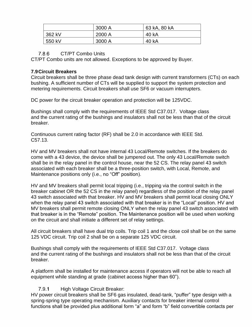
7.9 Circuit Breakers Circuit breakers shall be three phase dead tank design with current transformers (CTs) on each bushing. A sufficient number of CTs will be supplied to support the system protection and metering requirements. Circuit breakers shall use SF6 or vacuum interrupters. DC power for the circuit breaker operation and protection will be 125VDC. Bushings shall comply with the requirements of IEEE Std C37.017. Voltage class and the current rating of the bushings and insulators shall not be less than that of the circuit breaker. Continuous current rating factor (RF) shall be 2.0 in accordance with IEEE Std. C57.13. HV and MV breakers shall not have internal 43 Local/Remote switches. If the breakers do come with a 43 device, the device shall be jumpered out. The only 43 Local/Remote switch shall be in the relay panel in the control house, near the 52 CS. The relay panel 43 switch associated with each breaker shall be a three-position switch, with Local, Remote, and Maintenance positions only (i.e., no “Off” position). HV and MV breakers shall permit local tripping (i.e., tripping via the control switch in the breaker cabinet OR the 52 CS in the relay panel) regardless of the position of the relay panel 43 switch associated with that breaker. HV and MV breakers shall permit local closing ONLY when the relay panel 43 switch associated with that breaker is in the “Local” position. HV and MV breakers shall permit remote closing ONLY when the relay panel 43 switch associated with that breaker is in the “Remote” position. The Maintenance position will be used when working on the circuit and shall initiate a different set of relay settings. All circuit breakers shall have dual trip coils. Trip coil 1 and the close coil shall be on the same 125 VDC circuit. Trip coil 2 shall be on a separate 125 VDC circuit. Bushings shall comply with the requirements of IEEE Std C37.017. Voltage class and the current rating of the bushings and insulators shall not be less than that of the circuit breaker. A platform shall be installed for maintenance access if operators will not be able to reach all equipment while standing at grade (cabinet access higher than 60”).
High Voltage Circuit Breaker: HV power circuit breakers shall be SF6 gas insulated, dead‐tank, “puffer” type design with a spring‐spring type operating mechanism. Auxiliary contacts for breaker internal control functions shall be provided plus additional form “a” and form “b” field convertible contacts per

Table 15. Circuit breakers shall conform to IEEE C37. Circuit breaker ratings shall be as shown in Table 15.
Table 15: HV Circuit Breaker Ratings
Rated Maximum Voltage 72.5 kV 123 kV 145 kV 170 kV 242 kV
Rated Continuous Current (as specified)
1200 A 2000 A
2000 A 3000 A
2000 A 3000 A
2000 A 3000 A
2000 A 3000 A
Rated Short Circuit Current (to be determined after study results)
40 kA 40 kA 63kA
40 kA 63kA
40 kA 40 kA 63kA
Lightning Impulse Withstand Voltage 350 kV 650 kV 650 kV 750 kV 900 kV
Rated Interrupting Time 5 cycles 3 cycles 3 cycles 3 cycles 3 cycles Rated shunt Capacitor Switching current
630 A 315 A 315 A 400 A 400 A
Additional Auxiliary Contacts
Form “a” 12
Form “b” 12
SF6 Gas Breakers have an assortment of available alarms. These alarms shall be visible at an annunciator. All of the available alarms for HV breakers shall be inputs into the substation RTU and made available to the ERCC via the Ethernet switch. Communications cables shall be run between the substation RTU and the annunciator. The annunciator will be supplied by the breaker vendor. All HV circuit breakers shall have low SF6 pressure alarms and emergency operations for: Stage 1: Low gas pressure Stage 2: Auto‐trip of the Trip Coil 1 and Trip Coil 2 circuits and block close of the Close Coil circuit. Stage 3: Block‐trip of the Trip Coil 1 and Trip Coil 2 circuits and block close of the Close Coil circuit.
EHV Circuit Breakers (345 kV & 500 kV) Additional specific requirements pertaining to 345 kV & 500 kV circuit breakers will be provided under separate cover where applicable.
Medium Voltage: Collector Feeders and Reactive Breakers: MV Circuit breakers shall be rated for outdoor, three-poles, gang operated, dead tank, frame mounted vacuum type with motor charged operating mechanism in conform to IEEE C37. MV Circuit breaker ratings shall be as shown in Table 16.
Table 16: MV Circuit Breaker Ratings
Nominal Operating Voltage (phase‐to‐phase) 34.5 kV

Maximum Voltage (phase‐to‐phase) See Table 2
Basic Impulse Level (BIL)
Maximum Continuous Current (amperes) To be determined after
study results
Short Circuit Interrupting Current (kA) [40kA use conservativity. Final short circuit model shall dictate the final rating]
40kA with full back to back
switching capability; tested
and proven.
Interrupting Time (cycles) 3
Independent Pole (Phase) Operators N/A
Duty Cycle O‐0.3 sec – CO ‐3 min ‐ CO
Spring Motor Voltage 125VDC
AC Heaters and Receptacle Voltage 120/240VAC
Additional Auxiliary Contacts Forms “a” and “b”
7.10 Generator Step-up Unit (GSU) / Main Power Transformer (MPT) This section describes requirements for the Main Power Transformer (MPT) within the collector substation. This item is also referred to as the Generator Step-up Unit (GSU). The GSU connects the medium voltage collector system to the high voltage interconnecting transmission system. The GSU shall be built to ANSI/IEEE C57. The GSU shall be an outdoor, oil-filled power transformer, 65 degrees C temperature rise, and designed in accordance with the Project Site climactic conditions listed in Attachment 2. The GSU ratings shall be based on the project expected total generation and confirmed through software simulations. GSUs shall be purchased complete with bushing current transformers, tap changers, surge arresters, cooling equipment such as radiators & fans, and control/monitoring system equipment. Some specific functions for protection and control shall include:
a) Fault pressure relay circuits programmable as far as “trip” or “alarm” function.
b) Transformer Pressure Relief Devices (“PRD”) shall be wired to alarm only (no trip).
c) Transformer oil level shall be wired to alarm only (no trip).
d) Transformer temperature indication shall be wired to alarm only (no trip). Table 17 below provide some recommended transformer specifications to consider.
Table 17: Transformer Recommended Specifications
Project MW 270 250 200 150 100 20
Tra
nsfo
rmer
MV
A
ONAN 180 168 135 102 69 18
ONAF1 240 224 180 136 92 24
ONAF2 300 280 225 170 115
%Z (H‐X, Positive Sequence)
9.0%, 180 MVA
9.0%, 168 MVA
8.5%, 135 MVA
8.5%, 102 MVA
8.0%, 69 MVA
8.0%, 18MVA
X0 Neutral Reactor Yes Yes Yes Yes No No
Assumptions: 1. Power factor range required at point of interconnect is +/‐ 0.95
2. Inverters are capable of +/‐ 0.9 power factor
3. Substation is not close to synchronous generation switchyard
4. Transformers over 300 MVA not recommended due to 34.5 kV fault current 5. Based on transformer winding configuration: HV (wye‐gnd); XV (wye‐gnd); XV (delta‐buried)
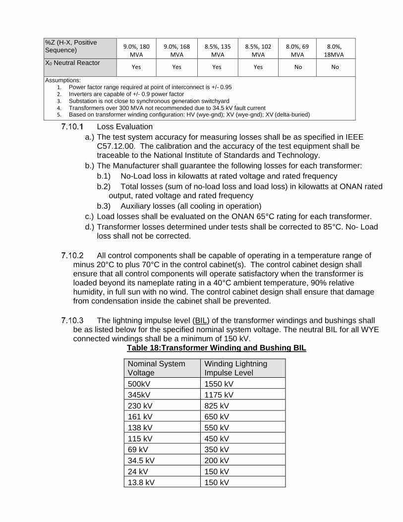
Loss Evaluation
a.) The test system accuracy for measuring losses shall be as specified in IEEE C57.12.00. The calibration and the accuracy of the test equipment shall be traceable to the National Institute of Standards and Technology.
b.) The Manufacturer shall guarantee the following losses for each transformer:
b.1) No-Load loss in kilowatts at rated voltage and rated frequency
b.2) Total losses (sum of no-load loss and load loss) in kilowatts at ONAN rated output, rated voltage and rated frequency
b.3) Auxiliary losses (all cooling in operation)
c.) Load losses shall be evaluated on the ONAN 65°C rating for each transformer.
d.) Transformer losses determined under tests shall be corrected to 85°C. No- Load loss shall not be corrected.
All control components shall be capable of operating in a temperature range of minus 20°C to plus 70°C in the control cabinet(s). The control cabinet design shall ensure that all control components will operate satisfactory when the transformer is loaded beyond its nameplate rating in a 40°C ambient temperature, 90% relative humidity, in full sun with no wind. The control cabinet design shall ensure that damage from condensation inside the cabinet shall be prevented.
The lightning impulse level (BIL) of the transformer windings and bushings shall be as listed below for the specified nominal system voltage. The neutral BIL for all WYE connected windings shall be a minimum of 150 kV.
Table 18:Transformer Winding and Bushing BIL
Nominal System Voltage
Winding Lightning Impulse Level
500kV 1550 kV
345kV 1175 kV
230 kV 825 kV
161 kV 650 kV
138 kV 550 kV
115 kV 450 kV
69 kV 350 kV
34.5 kV 200 kV
24 kV 150 kV
13.8 kV 150 kV

The transformer percent impedance at the self-cooled (ONAN) rating shall be as specified in Table 19 below (for 345 kV and 500 kV, requirements will be provided under separate cover);
Table 19: GSU Impedence
HV Winding Voltage
Impedance %
Without LTC With LTC
230 kV 10.0 10.5
161 kV 9.5 10.0
138kV 9.0 9.5
115kV 8.5 9.0
69 kV 8.0 8.5
34.5 kV 7.25 7.5
24 kV 6.75 7.0
13.8 kV 6.75 7.0
The maximum average winding temperature rise shall be 65°C. The maximum hottest-spot temperature rise of the winding shall not exceed 80°C. The maximum hottest-spot temperature rise of any metal components in the transformer core and tank whether in contact or not in contact with the paper insulation, shall not exceed 80°C at an ambient temperature of 40°C.
The calculated maximum temperature rise of any lead or connection shall not exceed the calculated maximum winding hottest spot temperature rise.
The temperature of any serviceable metal parts, gauges, switch handles, etc., located in the control cabinet that may be touched by an operator under normal operation shall not be affected by the transformer and shall not exceed the ambient temperature by more than 10°C at maximum rated load.
Winding hottest-spot calculations shall be made for each winding using the maximum localized losses including the eddy current losses, the insulation thickness at the points of maximum localized losses, and the oil rise in the winding. If the Seller is not able to measure the oil rise in the windings, an allowance will be made for the added rise at the design review. These results shall be used in calibrating the hot-spot temperature indicator.
The use of metal oxide varistor (MOV) or other internal devices to control voltage transients is not preferred. When used, their location shall be shown on the nameplate winding schematic. If internal arresters are used, they must be accessible form the top of the transformer without draining of the oil.

The calculated maximum temperature rise of any lead or connection shall not exceed the calculated maximum winding hottest spot temperature rise.
The sound pressure level of transformers with an equivalent two-winding rating of more than 25 MVA (ONAN) shall be 6 dB below the levels specified in the NEMA TR-1.
The inter-winding insulation system for windings shall be designed for a BIL impulse to one minute 60 Hz. withstand level ratio of 2.5 or less, using maximum voltage stress and with a safety margin of 20% for the oil space stresses. Weidmann oil gap curves shall be used to determine the field stresses.
Ancillary equipment such as bushings, tap changer, winding leads, etc., shall not restrict the transformer loading to levels below those permitted by the winding conductor. The transformer shall be capable of carrying loads above its nameplate rating in accordance with IEEE C57.91.
Short Circuit Capability
7.10.14.1 The transformer shall be designed and constructed to withstand, without damage, the effects of both three-phase and line-to-ground through-faults at either of the transformer HV, LV, or TV terminals. The windings shall not exceed the IEEE thermal limits for the duration of 2 seconds. The pre-fault operating voltage on the non-faulted terminals shall be 1.05 per unit rated voltage.
7.10.14.2 All windings shall be designed for an infinite bus condition i.e. system impedance shall not be used in the calculation of the fault currents. The inner windings shall be designed to withstand maximum short circuit forces in an unsupported buckling mode (free buckling), assuming no radial mechanical support from the core. The windings shall also be designed for forced or supported buckling.
a.) The transformer shall be designed according to the requirements of IEEE Std 693 Annex D. The transformer assembly shall be designed to withstand seismic loading as specified in IEEE 693..
b.) High temperature fiberglass or Nomex insulation or other Entergy approved high temperature material shall be used for the insulation between the tieplates and the core.
c.) The iron core shall be designed such that at full load and with 105% rated secondary voltage, the maximum core temperature (hotspot) shall not exceed 120°C (80°C rise at 40°C ambient), and the maximum tieplate or core surface temperature rise shall also not exceed 120°C (80°C rise at an ambient of 40°C).

Windings:
a.) All winding conductor material and all other current-carrying parts shall be copper or silver, or alloy(s) of copper and/or silver.
b.) The current density in the winding conductor under maximum rated power at 65°C temperature rise shall not exceed 4 A / mm2 (2580 amps per square inch).
c.) The winding conductor insulation shall be thermally upgraded paper meeting the life criteria as defined and verified in IEEE C57.100. The minimum nitrogen content of the upgraded paper when tested by ASTM standards shall not be less than 2%.
Tank
a.) All welding shall be in accordance with ANSI/AWS D1.1 / D1.1M, American Welding Society Steel Structural Welding Code.
b.) The transformer tank shall be of welded sheet steel construction, free from distortion.
c.) Shall withstand full vacuum without leakage or distortion. The transformer tank cover shall be welded on with at least a 20-inch diameter manhole.
The location of the "shipping" and "dressed" center of gravity shall be marked with raised letters and symbols on the transformer tank.
The oil preservation system shall be a sealed-tank system with a constant pressure inert gas-pressure or conservator/diaphragm system.
Bushings and Terminals
a.) All Bushings shall be in accordance with IEEE Std C57.19.01.
b.) The minimum BIL of the bushings shall be as tabulated below. Table 20: BIL ratings for GSU Bushings and Terminals
Nominal System Voltage
Rated Voltage of Bushing
Rated BIL of Bushing
500 kV 1675 kV
345 kV 1175 kV
230 kV 146 kV 900 kV
161 kV 102 kV 750 kV
138 kV 102 kV 650 kV
115 kV 88 kV 550 kV
69 kV 44 kV 350 kV
34.5 kV 22 kV 200 kV
24 kV 16 kV 150 kV,
13.8 kV 10 kV 150 kV,

c.) The rated current of the bushing shall be as specified in IEEE Std C57.19.01 but not less than 1.2 times the transformer load current corresponding to its maximum MVA rating with full cooling in operation. The bushing shall not restrict the transformer loading to levels below those permitted by the winding conductor. The rate of loss of life of bushing shall not be more than that for the transformer when the transformer is loaded beyond its nameplate rating in accordance with IEEE Std C57.91
d.) Bushing flange or (flange with adapter) sizes shall be such that the bushings and mountings supplied allow interchangeability with older IEEE standard bushings.
e.) All bushings including the neutral bushing shall be provided with test taps.
f.) All bushings shall be power factor tested. Values of “C1” and“ C2” shall be stamped on the bushing nameplates.
g.) The oil sight gauges or sight glass on cover-mounted bushings shall face “outward” so that the oil level sight glass in the bushing can be seen from ground level. All bushing nameplates are to face outward to allow reading of nameplates with spotting scope.
h.) All bushings shall be paper-oil condenser type
i.) Minimum clearance between the live parts of bushings and surge arresters to the components of the transformer that may be serviced (e.g. gas detector relay, valves, gauges, etc.) shall be in accordance with OSHA requirements. Bottom of the bushings shall be minimum 8.5 feet above ground including six inch foundation pad. Vertical clearance between the bushing terminal and the ground shall be in accordance with National Electrical Safety Code IEEE Std C2 requirements.
j.) Bushings shall have the following creepage distance in Table 21 Table 21: GSU Bushing Creepage Distance
System Voltage Creepage Distance
15 kV 15”
25 kV 25”
35 kV 35”
69 kV 69”
115 kV 115”
138 kV 138”
161 kV 161”
230 kV 230”
345 kV 345”
500 kV 415”

k.) The H2 and X2 bushings shall be located on the same centerline, and where practicable shall be on the main tank centerline.
l.) Minimum metal to metal clearance between the live parts of bushings in air shall be as tabulated below in Table 22
Table 22: GSU Bushing Minimum Clearance Between Live Parts
System Voltage (kV) Clearance (inches)
Up to 34.5 kV 24”
69 kV 32”
115 kV 48”
138 kV 60”
161kV 72”
230 kV 90”
345kV 120”
500kV 160”
Bushing Current Transformers
a.) Internal, multi-ratio, bushing-type current transformers (CT) shall be provided with all secondary terminals wired to shorting terminal blocks using ring type lugs.
b.) Typical CT Ratios are listed below in Table 23. For 345 kV and 500 kV, requirements will be provided under separate cover.
Table 23: GSU Bushing Typical CT Ratios
kV 600:5 1200:5 2000:5 3000:5 5000:5
13.8 12-14 MVA 19-28 MVA 28-47 MVA 47-71 MVA 71-100 MVA
14.4 12-14 MVA 19-29 MVA 29-49 MVA 49-74 MVA 74-100 MVA XFMR
24 12-24 MVA 33-49 MVA 49-83 MVA 83-100 MVA BUSHING WINDING 34.5 12-35 MVA 48-71 MVA 71-100 MVA VOLTAGE
(kV L–L)
MVA RATING:
3Ph @65C 69 12-71 MVA 95-100 MVA
115 12-100 MVA
138 12-100 MVA
161 12-100 MVA
230 12-100 MVA

c.) The continuous thermal current-rating factor RF for the bushing current transformers shall be 2.0 based on temperature rise in accordance with IEEE Std C57.13.
d.) All current transformers shall be multi-ratio with ratios in accordance with IEEE Std C57.13.
e.) Provision shall be made to remove and replace the CTs without removing the tank cover.

The manufacturer shall provide and include on the transformer(s) for the Project:
a.) Magnetic liquid level indicator with alarm contacts and threaded conduit hub, with two set points and two sets of alarm contacts per set point
b.) Liquid filling and filter press connection in the top and bottom of the tank
c.) Combination drain and bottom filter valve with sampler
d.) Dial-type liquid thermometer and temperature-indicating switch with alarm contacts, maximum read pointer, and threaded conduit hub, with two set points and two sets of alarm contacts per set point
e.) Vacuum pressure gauge with bleeder
f.) Lifting hooks on the tank, lifting eyes on the cover and provisions for jacking
g.) Stops shall be provided to prevent over-compression of gaskets; gaskets below oil level will be eliminated unless isolating valves are provided
h.) Pressure relief device with alarm contacts and threaded conduit hub
i.) A hot spot dial-type winding temperature indicator with alarm contacts shall be provided for each high voltage and low voltage winding, with a minimum of two (2) per transformer; each winding temperature indicator shall have two set points and two sets of alarm contacts per set point
j.) De-energized tap changer:
j.1) Conform to IEEE C57.12.10, Article 5.1.1.
j.2) Steps at +5%, +2.5%, 0%, -2.5%, and -5%.
j.3) Operable from ground level, with a single external lockable operating handle not more than five feet above ground level.
j.4) The tap setting indicator shall be visible from ground level.
j.5) Capable of withstanding without damage the short-circuit duty specified for the transformer.
k.) Load Tap Changer: A high-speed motor operated load tap changer with vacuum or resistance switching conforming to IEEE C57.12.10. Furnish as follows:
k.1) Range: plus-or-minus 10% in 32 - 5/8% steps with full MVA capacity on all taps above neutral position, and reduced MVA capacity on taps below neutral position. Preventive autotransformer (PA) if used shall be rated to maintain full capacity with the unequal steps.
k.2) Rated Current: not less than the maximum winding current at its rated maximum load (2 stages of supplemental cooling) even if provision only for cooling is initially supplied.
k.3) Tap position indicator: located where it can be readable and re-settable from the ground level and visible when manually operating the LTC. The position indicator shall have markings 16L – N - 16R to signify the Normal and the range extremes, and be in accordance with IEEE Std C57.12.10.
k.4) Each tap position indication shall provide a digital or analog output for indication in the substation control room and for SCADA indication.
k.5) Operation capability: Each contact shall be capable of 500,000 electrical and mechanical operations at the top MVA rating of the transformer before requiring contact replacement. The contacts shall be easily accessible.
k.6) The load tap changing equipment shall be contained in segment 2 in a compartment separate from the core and coils to prevent mixing of oil.
k.7) The hand crank for manual operation of the drive mechanism shall be operable while standing at the base of the transformer.

k.8) The automatic or manual operation of the LTC shall be blocked if the vacuum interrupter fails to interrupt and transfer the load current during a tap change operation.
k.9) LTC control relay. Wire to provide sequential or non-sequential operation.
k.10) LTC backup control relay
k.11) Latching relay for supervisory selection of AUTO or MANUAL REMOTE operation.
k.12) LTC Control devices: housed in the transformer control cabinet.
k.13) Switch for Manual-Off-Test-Auto control functions. A contact CLOSED when the selector switch is in either the “OFF” or “MANUAL” position shall be provided for the Purchaser's supervisory indication.
k.14) Switch for Local-Remote control.
k.15) Tap Position Indicator with Drag Hands.
k.16) Tap position indication sending unit
k.17) Operations Counter.
k.18) Raise/Lower Switch.
k.19) Automatic voltage control equipment.
k.20) Terminal blocks for cable connection.
k.21) Heaters for anti-condensation
l.) Stainless steel nameplates and tap changer warning/instruction plates; nameplates shall not be attached to the radiators
m.) Fans:
m.1) Three-phase and wired to an auxiliary cooling equipment control panel for power connection, individually fused or otherwise thermally protected, controlled by the winding hot spot temperature.
m.2) Shall not be located on top of the radiators nor directly mounted on radiator fins. Separate, removable mounting support for fans shall be supplied and bolted to the transformer tank.
m.3) Fan guards shall be hot-dipped galvanized, totally enclose the fan blades, and meet OSHA safety requirements.
n.) The radiators shall be equipped with bolted flanges and valves to permit the removal of any radiator without draining the oil from the transformer or any other radiator; lifting eyes shall be provided on each radiator/cooler group
o.) Connection provisions shall be made in the cooling equipment controls circuit to allow external interlocking with the transformer protective relaying scheme, such that operation of normally closed contacts of the transformer protection lockout relay (86T) will shut down the cooling equipment in the event of an internal transformer fault
p.) Copper grounding pads shall be provided at opposite corners of the tank base. A NEMA 4-hole compression type lug for connection of a 500 kcmil ground cable to the station ground grid shall be provided for each ground pad and for the transformer neutral bushing ground connection which shall be bussed to the tank base.

q.) Insulating Oil: Seller shall ensure the manufacturer fills the tank with oil and the transformer shall be provided with the necessary amount of high-grade insulating oil that contains no detectable PCBs; the oil shall be manufactured and tested in accordance with the requirements of ASTM D3487; identification of non-PCB liquid shall be placed on outside of tank.
r.) Bushing mounted, station-type lightning arresters. Arrester ratings shall be as follows:
Table 24: GSU Arrester Ratings
System Voltage
Surge Arrester Rated Voltage
Surge Arrester MCOV
500 kV 420 kV 335 kV
345 kV 276 kV 220 kV
230 kV 192 kV 152 kV
161 kV 132 kV 106 kV
138kV 120 kV 98 kV
115kV 96 kV 76 kV
69 kV 60 kV 48 kV
34.5 kV 30 kV 24.4 kV
24 kV 21 kV 17 kV
14.4 kV 12 kV 10.2 kV
13.8 kV 12 kV 10.2 kV
13.2 kV 12 kV 10.2 kV
4.16 kV 6 kV 5.1 kV
2.4 kV 3 kV 2.55 kV

The height, from base to the terminal, of the arresters up to 34.5 kV shall be the same as that of the associated LV bushing to reduce probability of flash cause by wildlife. Spacers should be added at the base of the arresters if necessary.
s.) All control wiring shall be 600-volt, 90 degrees C, and XLPE insulation, with stranded copper wire, No. 12 AWG (minimum) for power, No. 14 AWG (minimum) for controls, and No. 10 AWG (minimum) for current transformers
t.) Terminal blocks shall be rated for 600 volts and accept conductors sized #18 through # 8 AWG; an additional 20% spare or extra terminal blocks shall be provided; heat shrink wire markers are required
u.) A core grounding strap shall be provided and accessible from a tank top man-way.
v.) Radiators
v.1) Radiators shall be detachable from the main tank and shall preferably be interchangeable.
v.2) Studs welded to the tank or headers for mounting of the radiators are not acceptable.
v.3) Radiator shut-off valves (butterfly type) shall be provided for each detachable radiator or header, at both top and bottom openings to the main transformer tank. It shall be possible to remove individual radiators for maintenance without the loss of cooling from other radiator banks. The open and closed positions on the radiator shut-off valves shall be clearly and marked
v.4) Radiators shall be heavy hot-dip galvanized in accordance with ASTM A123. As measured in accordance with ASTM A386, minimum zinc-coating thickness shall be 3 mils or
v.5) 1.8 oz/ft2. If any repair of the galvanizing coating is necessary, Supplier shall make such repairs in accordance with ASTM 780.
v.6) Radiator banks shall have lifting eyes.
w.) Cooling Equipment Control
w.1) Winding temperature indicators/sensors shall be calibrated to simulate the winding(s) actual hottest spot temperature and shall actuate automatic control of the fans.
w.2) An alarm relay shall be provided for each stage for cooling failure.
w.3) A two-position “Fan Transfer Switch” shall be provided to allow selection of either bank of cooling equipment to operate on either stage of cooling.
w.4) A three position switch shall be provided to allow manual or automatic operation of cooling equipment. Switch positions shall be marked Auto-Off-Manual.
w.5) Each bank of cooling equipment shall be fed separately from and protected by a two pole breaker of adequate rating, 20 kA interrupting capacity minimum.
w.6) Means shall be provided to turn off the cooling system with a remote contact.
x.) Control Cabinets
x.1) Shall comply with the requirements of IEEE C37.21.

x.2) The inside pocket on the door shall contain one copy of the instruction manual. Cabinets wider than four (4) feet shall have two approximately equal sized doors.
x.3) All control, power, CT, cooling system and alarm wiring shall be terminated in the control cabinet. The control cabinet shall be insulated from transformer so that the "vibrations and heat" are not transmitted to devices within the cabinet.
x.4) Sufficient space and clearances shall be provided at the bottom of the cabinet to facilitate cable entry and termination.
x.5) Heaters: The heaters shall be rated to operate at 120 V ac and each heater shall be on its own circuit, protected by an appropriate 20 kA interrupting capacity circuit breaker. The heaters shall be PTC (Positive Temperature Coefficient for temperature limiting) heater(s) of sufficient size to prevent moisture condensation. Fan-less PTC heaters, where used, shall be oriented to facilitate convective air flow over their fins to maximize heat transfer.
x.6) A 120 volt 15 Amp weatherproof convenience duplex receptacle with ground fault protection shall be provided on the exterior of the control cabinet. A circuit breaker for this receptacle shall be provided inside the cabinet.
x.7) Lighting: Shall have a switched convenience light. Large cabinets shall have two switched convenience lights.
x.8) The cabinet shall be provided with a grounding bar for individually grounding current transformers, control cable shields, etc.
y.) Auxiliary cooling equipment control cabinet:
y.1) loss of auxiliary cooling power alarm (fans not running)
y.2) Components shall be mounted in a weatherproof enclosure of NEMA 4X design or better
y.3) Terminal block enclosures will be provided with space heater(s) and internal illumination by standard lamps(s), 120-VAC, with a door-activated on-off switch and guard for the lamp(s).
z.) Provisions for a fall protection system
aa.) All standard accessories and maintenance devices as applicable and described in IEEE Std C57.12.10
bb.) The oil preservation system of transformer with a conservator shall be equipped with an automatically self-regenerating, maintenance-free dehydrating breather to prevent outside air from having direct contact with the desiccant. A separate unit shall be supplied for the LTC gas space (if applicable). Separate tap-changer compartments shall be equipped with separate dehydrating breathers. Top of the breathers shall be within approximately five feet of the transformer base.
See Section 10.1.4 for additional requirements
Generator Step-Up Transformer Warranty The GSU transformer(s) shall be provided with an original equipment manufacturer’s warranty that the GSU transformer(s) shall be free from defects in material, manufacture, workmanship, and design for a minimum period of five (5) years from the date of such GSU transformer’s energization; provided that, if such GSU transformer has not been energized within six (6)

months after delivery thereof to the Project Site, the warranty period shall be at least five (5) years commencing six (6) months after the date of delivery to the Project Site. The GSU transformer manufacturer shall be required to repair or replace at its cost any GSU transformer (or component thereof) in breach of such warranty. The warranty shall cover the cost of removal from the Project Site, transportation to and from the repair facility, reinstallation after repairs, and any and all other “in and out” work.
7.11 Neutral Grounding Reactor (NGR) The neutral grounding reactor shall be used to limit the fault current magnitude on the 34.5kV. The rating of the NGR shall be based on underground collection design, short circuit analysis and ampacity calculation design criteria. Table 9 shows typical MPT MVA where the X0 Neutral Grounding Reactor is required. The requirement of the NGR shall be evaluated during planning phases.
7.12 Station Service Transformer (Auxiliary Loads) All HV substations, and other major and strategic substations, shall be provided with two independent AC station service sources with automatic transfer from one source to the other for redundancy. Recommended station service ac voltage ratings is as follow:
• 240/120 V AC 60Hz, single phase, 3 wire. The AC station service capacity shall be sufficient to supply all loads for the following as applicable:
a) Control house lighting, heating, and air conditioning,
b) Power transformer cooling fans, pumps, LTC and control cabinet space heaters,
c) Circuit breaker control cabinet heaters, and operating mechanism charging motors,
d) Substation lighting,
e) Battery chargers.
f) Maintenance equipment, including gas cart, and oil filter truck if feasible
g) Future Loads Approved sources of ac station service include the following:
a) Distribution line(s) area feeder
b) Distribution transformer connected to a substation bus
c) Station Service voltage transformers (SSVT) up to 230 kV (suitably rated for this service, but not less than 50 kVA)
The normal primary station service source is from a MV source in the substation (power transformer load side or on MV bus) with the backup station service from an independent MV source within the station or from an area feeder. SSVTs are used as the primary station service source in critical substations or in substations up to 230 kV without a MV source. The backup station service in such substations shall be from a nearby area distribution feeder based on economics and station importance. If a distribution feeder is not available, then a second SSVT shall be used as a backup. The SSVTs shall have

sufficient kVA rating to be able to supply all substation loads including maintenance equipment. SSVTs are typically connected to the substation bus or a transmission line and are within the associated primary protection zones. Surge protection shall be required on the HV side of the SSVT unless arresters protecting other equipment are close enough to protect the SSVT. Alternate sources of AC station service, including but not limited to the following, are to be used only in special circumstances and require Buyer approval.
a) Inverter system
b) Solar panels
c) Autotransformer tertiary
d) SSVTs above 230kV
An engine generator shall not be acceptable for providing AC station service source. See IEEE Std. 1818; Guide for the Design of Low-Voltage Auxiliary Systems for Electric Power Substations for additional guidance.
7.13 Reactive Equipment Reactive equipment used to provide power quality and reliability to the electrical system (where required) shall be done through capacitor banks and reactors at the 34.5 kV level. To protect and control the reactive equipment, a circuit/reactor switcher shall be used. The MV circuit breaker (See Section 7.9.2) shall be used to protect for external faults of the reactive zone of protection (bus differential, etc.)
Circuit Switcher Circuit switchers may be used for the switching of power transformers and shunt capacitor banks with Buyer approval. For switching of the shunt capacitor banks rated up to and including 170 kV, the circuit switchers shall be equipped with pre-insertion resistors for suppression of transients. Applications where a fully rated dead tank circuit breaker is not justifiable and circuit switcher with a desired fault interrupting rating is not available, a live tank circuit breaker without post type instrument current transformers may be considered in lieu of circuit switcher with Buyer approval. Circuit switchers are typically rated to interrupt lower fault currents than circuit breakers. As the circuit switchers are normally installed to protect shunt capacitor banks, they are assigned to be rated to the expected capacitive switching current as mentioned in the IEEE standards. The circuit switcher application shall ensure that these ratings are not exceeded.
Shunt Reactors Air core reactors present unique design and safety considerations because they produce very high magnetic fields during normal operation. Space to adjacent iron and steel structures and apparatus must be sufficient to prevent induction heating. Personnel safety must be considered. Safety fencing with Reactor Safety Signage is normally needed to prevent personnel from getting too close to a set of reactors. A worker approaching too close could experience overheating of ferrous items he is carrying. There is danger that implanted medical

electronic devices such as pacemakers, insulin pumps, or hearing aids will malfunction or fail, causing injury or death. The manufacturer’s documentation shall include minimum phase spacing and magnetic clearance requirements for perimeter fencing and these requirements shall be adhered to in the design of the substation. The Substation Designer shall consult with the manufacturer of the reactors with any additional questions including clear instructions for reactor grounding. To protect personnel working near the reactors the Substation Designer shall also request the manufacturer to supply magnetic field plots, needed to determine the perimeter fence spacing. The ratings of the shunt reactors shall be provided during detail analysis (project specific not required in all projects).
Shunt Capacitor Banks Shunt capacitor banks may be installed in ungrounded wye configuration up to 115 kV, and shall be grounded wye for 138 kV and above. Fuseless capacitor units shall be installed in capacitor banks. Seller must obtain Buyer approval for any exception. The ratings of the shunt capacitor banks shall be provided during detail analysis (project specific not required in all projects).
7.14 Control House
General There shall be no wood framing or trim. Eave height is to be manufacturer's standard to accommodate a clear interior height of 10'-0" (minimum) including specified insulation. See Section 8.2.5 for control house structural design information.
Roof All roof panels in all locations shall have a U.L. wind uplift classification of class 90 (minimum).
Ceiling Insulation shall be R-19 minimum and shall have a U.L. Flame Spread Rating of 25 (minimum).
Walls For metal buildings, the exterior building walls shall be constructed with a minimum of 16-gauge aluminized steel (or a zinc-aluminum finish), flat or corrugated surface, with a factory baked on light reflecting finish including a minimum ten-year guarantee. For concrete buildings, the exterior building walls shall be solid concrete design with 6” walls and steel rebar reinforced high strength concrete. The building walls shall be insulated with a non-combustible blanket type insulator with a glued-on vapor barrier facing material rated at R-11 (minimum) and a U.L. Flame Spread Rating of 25 (minimum).
Doors Substation control house doors shall be level 3 full flush doors (Level 3 - 16 gauge per
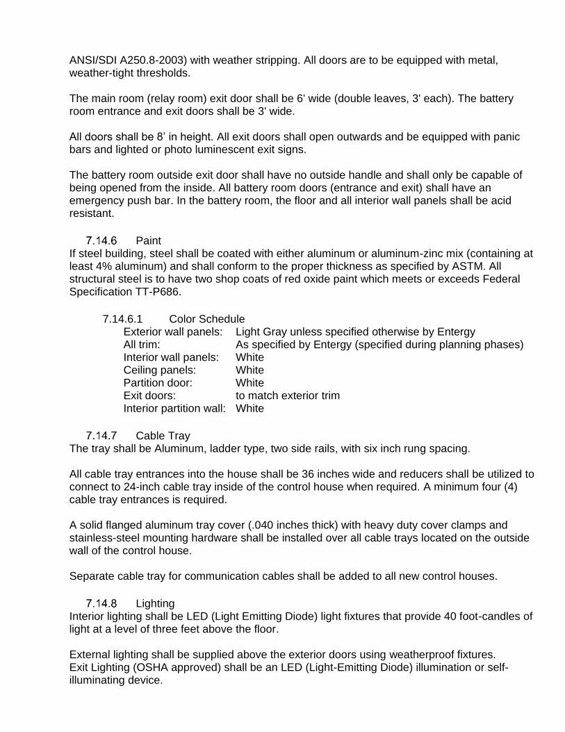
ANSI/SDI A250.8-2003) with weather stripping. All doors are to be equipped with metal, weather-tight thresholds.
The main room (relay room) exit door shall be 6' wide (double leaves, 3' each). The battery room entrance and exit doors shall be 3' wide. All doors shall be 8’ in height. All exit doors shall open outwards and be equipped with panic bars and lighted or photo luminescent exit signs. The battery room outside exit door shall have no outside handle and shall only be capable of being opened from the inside. All battery room doors (entrance and exit) shall have an emergency push bar. In the battery room, the floor and all interior wall panels shall be acid resistant.
Paint If steel building, steel shall be coated with either aluminum or aluminum-zinc mix (containing at least 4% aluminum) and shall conform to the proper thickness as specified by ASTM. All structural steel is to have two shop coats of red oxide paint which meets or exceeds Federal Specification TT-P686.
7.14.6.1 Color Schedule Exterior wall panels: Light Gray unless specified otherwise by Entergy All trim: As specified by Entergy (specified during planning phases) Interior wall panels: White Ceiling panels: White Partition door: White Exit doors: to match exterior trim Interior partition wall: White
Cable Tray The tray shall be Aluminum, ladder type, two side rails, with six inch rung spacing. All cable tray entrances into the house shall be 36 inches wide and reducers shall be utilized to connect to 24-inch cable tray inside of the control house when required. A minimum four (4) cable tray entrances is required. A solid flanged aluminum tray cover (.040 inches thick) with heavy duty cover clamps and stainless-steel mounting hardware shall be installed over all cable trays located on the outside wall of the control house. Separate cable tray for communication cables shall be added to all new control houses.
Lighting Interior lighting shall be LED (Light Emitting Diode) light fixtures that provide 40 foot-candles of light at a level of three feet above the floor. External lighting shall be supplied above the exterior doors using weatherproof fixtures. Exit Lighting (OSHA approved) shall be an LED (Light-Emitting Diode) illumination or self-illuminating device.
Air Handling The battery room exhaust fan shall be rated for 90 cfm. Battery room exhaust fan(s) shall be equipped with animal deterrent and mounted 8 feet above the floor for security purposes. Exhaust fan(s) shall be controlled and operated with an electro-mechanical timer. Operation intervals of exhaust fan shall be a minimum of four twenty-minute cycles every twenty-four hours. The air conditioner shall be controlled by a remote low voltage heating/cooling control thermostat, such as Accustat Energy Guard or equivalent, with design set points of 78°F for cooling and 68°F for heating.
WARRANTY Building finish: minimum twenty (20) year non-prorated warranty. The walls, including all wall openings for doors and louvered openings, are to be warranted weather-tight for a period of five years from the date of completion of the building. Ceiling: minimum ten (10) year warranty. Roof: minimum twenty (20) year non-prorated warranty. A full five-year warranty on the control house including equipment with parts and service is to be included.
8.0 Substation Civil/Structural Design Criteria
Seller shall complete all civil works to furnish a collector substation site design, access road(s), and any other outdoor civil works required inside the Project Site or as needed for interconnection of the Project to the ELL Transmission System. The design shall meet all applicable federal, state, and local Laws and regulations and requirements of the Agreement, including the Scope Book and this Attachment, and provide a relatively maintenance-free design (e.g. provide adequately-sized culverts to limit the possibly of clogging, provide erosion control means on slopes to eliminate maintenance re-grading, design access road cross-section to minimize rutting, etc.).
8.1 Siting and Civil
Floodplain
8.1.1.1 Flood Risk Evaluation Flood risk shall be evaluated, and an Elevation Basis selected. This includes evaluation of the flood risk to the substation from rain, river elevation, storm surge, or other causes. It also includes the placement of structures within known Federal Emergency Management Agency (FEMA) special flood hazard areas (SFHA) or other flood prone areas.
The substation location flood evaluation and decisions made with respect to site and equipment elevations shall be documented on the applicable substation site and foundation drawings. The process to establish the Elevation Basis shall be as follows:

a.) Determine if the site location is located within or near a FEMA SFHA.
b.) If published information is available, determine the Base Flood Elevation (BFE, 100-year flood) of the proposed site and if the location is within or adjacent to a mapped floodplain.
c.) Evaluate the FEMA Flood Insurance Rate Map (FIRM) to determine the most recent revision to the map (including Letters of Map Revision).
d.) Determine the date of the underlying Flood Insurance Study (FIS), if the FIS is available, and if the FIS method can be determined.
e.) Evaluate local development and the potential impacts to flooding since the publication of the FIS.
f.) Obtain written documentation about local ordinances regarding development in a SFHA, including any local requirements for development.
g.) For locations outside of a mapped SFHA, but that are suspected to be at an elevated flood risk, document the known information and attempt to quantify the risk in relation to the site. An example of this type of risk evaluation is floodway extents or floodplain extents ending in a straight line in the vicinity of the site. This occurrence might indicate a road or railway embankment but may be indicative of an arbitrary study limit.
h.) Determine planned access routes to the site for construction, operation, and maintenance and if such routes could be adversely affected by surface water flooding. The evaluation should consider the probability of surface water flooding at critical elevation points such as control houses, equipment cabinets, and access roads for the expected life cycle of the facility.
i.) If the site is located within a FEMA SFHA, the underlying FIS was conducted within the previous 10 years, and the 100-year BFE is available, the 100-year BFI shall be used as the Elevation Basis.
j.) If the site location is not located in a FEMA SFHA, the FIS was conducted more than 10 years ago, or the BFE is not otherwise available, engineering judgement and input from the Project Team shall be utilized to determine if local knowledge will be used as a basis for the site and equipment elevations or if a Hydrologic and Hydraulic study by a suitably experienced individual or company would need to be performed to determine.an Elevation Basis. If it is deemed a study is needed to determine a proper Elevation Basis, a study should be ordered along with a site topographic survey. If applicable, the study shall be used to determine the Elevation Basis.
8.1.1.2 Flood Design Requirements The Finished Grade of the site shall be at or above the Elevation Basis. Equipment foundation top of concrete (TOC) elevations shall be a minimum of one (1) foot above the Elevation Basis and a minimum of six (6) inches above the Final Grade. The final TOC elevations shall be chosen to keep all equipment control cabinets a minimum two (2) feet and if possible four (4) feet above the Elevation Basis. The Project Team will determine the Elevation Basis, make the final TOC elevation determination, and document those determinations. The TOC elevations shall be recorded on the station foundation plan and foundation details. When establishing the TOC elevation for the control house foundation, the relative elevations of the control house and equipment control cabinets shall be evaluated. In all stations the control house floor shall be a minimum of six (6) inches above the Final Grade to prevent rain water

from entering the house. If the control house has trenches in the floor then the bottom of the trenches shall be a minimum of six (6) inches above final grade. In stations within a FEMA SFHA or otherwise determined to be prone to flooding, the control house floor should be at or above the elevation of the bottom of the lowest equipment control cabinet. A higher control house elevation may be selected to allow for easy maintenance access under the house. In existing substations where the control house is raised due to flooding concerns, the ability to raise equipment cabinets to the same elevation as the control house floor should be evaluated for feasibility.
Earthwork
The existing site shall be cleared, grubbed/stripped to a depth sufficient to remove organic material, leveled, filled, compacted, and sloped to drain. The substation yard shall be graded to accommodate drainage. The preferred substation site shall be graded with a slope of no less than 0.5% ‐ 1.5% to facilitate water drainage from the site, storm sewers, catch basins, and/or manholes may be used if required for proper drainage.
A soil drainage analysis may be performed at the same time as soil boring investigation to determine the site’s characteristics for water infiltration and retention for sites with aggregate implications larger than 1 acre where AHJs may require additional site permitting.
The drawings shall note the control points on the site, and which coordinate system is to be used.
Erosion Control The design shall comply with the Storm Water Pollution Prevention Plan (SWPPP) and Environmental Management Plan (EMP).
Wetland Delineation and Mitigation Seller shall comply with all wetland requirements specified by Laws, applicable Permits, and the Performance Standards. Wetlands shall be confirmed by a qualified third party.
Stormwater Management
8.1.5.1 Seller shall design the Project Site stormwater management plan. Seller shall complete and submit all necessary permitting applications, including stormwater discharge NPDES Permit applications, to the appropriate Governmental Authorities. The design shall provide quality control of stormwater prior to discharge.
8.1.5.2 Seller’s design for stormwater management on the Project Site shall meet stormwater quality and quantity requirements of local, state, and, if applicable, federal Governmental Authorities. The design shall consist of the following, as a minimum:
a.) Size and design details of stormwater, oil containment, run-off basin, and outfall
b.) Location and size of stormwater piping, inlets and manholes as needed
c.) Location and size of stormwater ditches or channels
d.) Project Site relative grades and slope including the drainage area to each stormwater feature

Site Surfacing
a.) Thickness: The Project Site shall be graded to drain and then be surfaced with a minimum of six inches of compacted crushed stone.
b.) Aggregate shall meet one of the following:
b.1) Material designation - #610- Crushed limestone, primarily used in the Entergy system.
b.2) Material designation - Arkansas Department of Transportation Class 7 Base - Crushed granite or limestone, primarily used in Arkansas. Class 7 Base is a new designation that replaces the old designation (SB2). The materials in Class 7 and SB2 have the same gradation,.
b.3) Material designation - Grade D Base (DGA) Dense Grade Aggregate m- crushed limestone, primarily used in La.
c.) Compaction: The crushed stone shall be compacted to a minimum density equal to 95% of the maximum density obtained by a Modified Proctor Test (ASTM D-1557). Do not grade ruts down; fill with additional aggregate and compact.
d.) Sterilant: after sub grade preparation and prior to applying the crushed rock, a non‐toxic vegetation eradicator (sterilant) shall be applied. Sterilant shall be applied from a minimum of five feet to a maximum of ten feet outside the fence.
Drive Access and Road Design Substation ingress/egress points are to be compliant with all State and local permitting requirements. A permanent all-weather twenty (20) feet wide roadway shall be provided for access and egress to the substation site directly from a public street or road. Access Road shall be adequate for construction and maintenance activities including hauling heavy equipment such as the collector substation GSU. Access Road shall have no less than 50 ft. centerline turn radii. Roadways within the substation shall be provided, along the fence if possible, for personnel and equipment movement. All roadways within the substation shall be at least twenty (20) feet wide with at least a fifty (50) feet centerline minimum turn radius. A reduced turn radius inside the substation is acceptable provided that an 18-wheeled low-bed vehicle loaded with equipment can easily negotiate all roads and turns within the substation fence enclosure. Road crossings over cable trenches, and culverts, shall be designed to withstand heavy traffic. Substation shall have only two point of entry in and out of the yard. The yard shall allow for vehicles to turn around or back out of the yard. Note that new substations designated as CODE (see Section 11.0) shall include a vehicle access corridor around the exterior of the perimeter to allow drive-around access by security or law enforcement personnel.
Oil Containment
8.1.8.1 Federal Regulatory Requirements Design and construction shall conform to Code of Federal Regulations, Title 40, (40CFR), Parts 110 and 112. Oil spill containment shall be provided for the main transformer. Oil spill containment shall be provided for other equipment when required by authority having jurisdiction.

8.1.8.2 State and Local Regulatory Requirements Oil containment shall comply with state and local requirements which are contained in 40 CFR Part 109. State and local governments have generally adopted the existing federal regulations prohibiting discharges of oil.
8.1.8.3 Containment System
a.) Secondary oil containment type shall be an above grade containment pit.
b.) Minimum containment volume is to be 100% of oil contained within protected equipment in addition to the volume of rainwater retained during a 24-hour 25-year recurrent interval storm event.
c.) All designed water removal systems shall incorporate a method of monitoring discharged water quality. Monitors shall be connected to alarm systems.
d.) In designing (sizing) a stone filled collection pit, the final oil level elevation shall be situated approximately 12 inches below the top elevation of the stone. This provides a fire extinguishing capability designed to quench flames if a piece of oil filled equipment catches fire. The use of 1.5 inch or larger stone (washed and uniformly sized) is recommended to permit quicker penetration to avoid a pool fire. Void Volume Ratio for stone filled devices shall be between 30 to 40 percent.
e.) Pits using drainpipes shall assure that the drainpipe material shall be capable of withstanding the higher temperatures associated with an oil fire.
Oil Filled Equipment Separation Oil‐filled equipment shall be separated from other equipment and buildings to prevent potential fire hazards that may impede restoring or maintaining electric service. The following minimum separations from NFPA 850 Section 5.1.4 are suggested:

a.) Power transformers containing between 500 and 5,000 gallons of oil shall be located a minimum of 25 feet from any building unless the exposed walls consist of or are protected by a wall or barrier having a two‐hour fire rating. The barrier shall extend horizontally and vertically such that any exposed part of the building is a minimum of 25 feet from the transformer. Transformers shall also be spaced an adequate distance from a fire‐rated building wall to ensure that this 25-foot minimum is maintained to any other parts of the building that do not have a two‐hour fire rating.
b.) For outdoor transformers with an oil capacity of greater than 5,000 gallons, maintain clear separation of 50 feet from other structures or provide a 2-hour fire rated barrier
c.) A minimum distance of 8 feet shall exist between the transformer and any building or wall to ensure there is adequate space for normal operating and maintenance work. Cable trenches shall not be routed adjacent to oil immersed equipment.
d.) Barriers that are required due to inadequate separation to equipment or buildings shall be constructed of non‐combustible, heat‐resistant, fire‐rated material. The barrier height shall extend a minimum of 1 foot above the top of any oil filled equipment and any of their components. Barriers shall also extend horizontally a minimum of 2 feet beyond the line of sight of the subject building or equipment.
e.) For transformers with less than 500 gallons of oil and where a firewall is not provided, the edge of the postulated oil spill (i.e., containment basin, if provided) should be separated by a minimum of 5 feet from the exposed structure to prevent direct flame impingement on the structure.
f.) Any transformer for the Project using a listed “less flammable” insulating oil (e.g., Envirotemp FR3) shall be installed with and maintain a separation distance and barriers as provided above. If Seller seeks a modification of a separation distance or a barrier requirement for a transformer on the basis that the transformer will use a listed less flammable insulating oil, Seller shall perform and provide to Buyer a detailed hazard evaluation of such transformer with the proposed less flammable insulating oil. Buyer will consider such evaluation in its review of the modification request.
8.2 Structures and Foundations
Code and Standards The structural design of the substation shall be in accordance with the latest revision of industry codes, standards, and design guides unless stated otherwise. Applicable federal, state and local codes and standards shall also be observed. The following industry codes and standards shall be observed for civil/structural design. The latest issued Standards and Codes at the issuance of the effective date of the Agreement shall be used. Earlier editions are not allowed unless specifically identified in this Attachment. If a revision to a standard or code is issued, it is not required to be implemented unless the Authority Have Jurisdiction (AHJ) has adopted it, in which case, the Seller is obligated to any increased compliance above what is required by the Standards and Codes at the effective date of the Agreement. This risk is to be borne by the Seller.

• American Concrete Institute (ACI)
o ACI 318: Building Code Requirements for Structural Concrete
• American Institute of Steel Construction (AISC)
o AISC 360: Specification for Structural Steel Buildings
• American National Standards Institute (ANSI) standards
• American Society for Testing and Materials (ASTM) standards
• American Society of Civil Engineers (ASCE)
o ASCE 113: Design of Substation Structures
o ASCE 48: Design of Steel Transmission Pole Structures
• American Welding Society (AWS) D1.1
• International Building Code
• Concrete Reinforcing Steel Institute (CRSI) standards
• Institute of Electrical and Electronics Engineers (IEEE)
o IEEE Std 605-2008: IEEE Guide for Bus Design in Air Insulated Substations
o IEEE Std 693-2018: IEEE Recommended Practice for Seismic Design of Substations
o IEEE Std 1527-2018: IEEE Recommended Practice for the Design of Buswork Located in Seismically Active Areas
Other recognized standards and ordinances shall be used where required, to serve as guidelines for the design, when not in conflict with the above listed standards.
Equipment Support Structure Loading
8.2.2.1 Load Cases The load cases specified shall include the following environmental requirements:
a.) Dead Load: The weight of equipment and support structures shall be included with appropriate increases for all equipment accessories and structure connections.

b.) NESC District Loading (Rule 250B) - NESC District Loading shall be selected from Table 25, Table 26, Table 27, or Table 28 based on project location (Note that these districts may not match the district depicted in NESC for a given county).. The ambient air temperature shall be taken as 0°F. Note that the load factors specified in NESC Table 253-1 shall only be used for this condition.
c.) Extreme Wind: An Extreme Wind Speed shall be selected from Table 25, Table 26, Table 27, or Table 28 based on project location (Note that the values in the tables may not match the maps depicted in NESC or ASCE 113 for a given county). Wind pressure shall be developed using ASCE 113. The importance factor (IFW) for Extreme Wind loading shall be 1.0 corresponding to a 50-year mean recurrence interval per ASCE 113, Table 3-3. The ambient air temperature shall be taken as 60°F.
d.) Concurrent Ice and Wind: A wind speed of 30 mph from any direction and a radial ice thickness selected from Table 25, Table 26, Table 27, or Table 28: Load Districts by County – Texas based on project location applied on the equipment or structure. The importance factor (IFI) for Concurrent Ice and Wind loads shall be 1.0 corresponding to a 50-year mean recurrence interval per ASCE 113, Table 3-11. The ambient air temperature shall be taken as 15°F.
e.) Short Circuit Loading: Determined in accordance with ASCE 113 and IEEE 605-2008 using electrical parameters determined from a site-specific analysis.
f.) Seismic: Seismic design parameters (accelerations, site class, etc.) will be provided in the geotechnical report for each site. The seismic loads shall be calculated in accordance with ASCE MOP 113. Unless larger values are provided in the geotechnical report, the following minimum values shall be used for the mapped ground motion spectral response accelerations: Ss = 0.140 and S1 = 0.051. The ambient air temperature shall be taken as 60°F.
g.) Other: For equipment mounted on structures, the same design weather conditions shall apply. Loads associated with operation of the equipment shall be added to applicable load combinations.

Table 25: Load Districts by County – Arkansas and Missouri
State
County
Extreme NESC District Concurrent Ice
& Wind Case
Ice Thickness
Wind Light Medium Heavy
mph inches
AR Arkansas 100 M 1
AR Ashley 100 M 1
AR Baxter 100 H 1
AR Benton 100 H 1
AR Boone 100 H 1
AR Bradley 100 M 1
AR Calhoun 100 M 1
AR Carroll 100 H 1
AR Chicot 100 M 1
AR Clark 100 H 1
AR Clay 100 H 1
AR Cleburne 100 H 1
AR Cleveland 100 M 1
AR Columbia 100 M 1
AR Conway 100 H 1
AR Craighead 100 M 1
AR Crawford 100 H 1
AR Crittenden 100 M 1
AR Cross 100 M 1
AR Dallas 100 M 1
AR Desha 100 M 1
AR Drew 100 M 1
AR Faulkner 100 H 1
AR Franklin 100 H 1
AR Fulton 100 H 1
AR Garland 100 H 1
AR Grant 100 M 1
AR Greene 100 H 1
AR Hempstead 100 H 1
AR Hot Spring 100 H 1
AR Howard 100 H 1
AR Independence 100 H 1
AR Izard 100 H 1
AR Jackson 100 H 1
AR Jefferson 100 M 1
AR Johnson 100 H 1
AR Lafayette 100 M 1
AR Lawrence 100 H 1
AR Lee 100 M 1
AR Lincoln 100 M 1
AR Little River 100 H 1
AR Logan 100 H 1
AR Lonoke 100 M 1

State
County
Extreme NESC District Concurrent
Ice & Wind Case Ice
Thickness
Wind Light Medium Heavy
mph inches
AR Madison 100 H 1
AR Marion 100 H 1
AR Miller 100 M 1
AR Mississippi 100 M 1
AR Monroe 100 M 1
AR Montgomery 100 H 1
AR Nevada 100 M 1
AR Newton 100 H 1
AR Ouachita 100 M 1
AR Perry 100 H 1
AR Phillips 100 M 1
AR Pike 100 H 1
AR Poinsett 100 M 1
AR Polk 100 H 1
AR Pope 100 H 1
AR Prairie 100 M 1
AR Pulaski 100 H 1
AR Randolph 100 H 1
AR St. Francis 100 M 1
AR Saline 100 H 1
AR Scott 100 H 1
AR Searcy 100 H 1
AR Sebastian 100 H 1
AR Sevier 100 H 1
AR Sharp 100 H 1
AR Stone 100 H 1
AR Union 100 M 1
AR Van Buren 100 H 1
AR Washington 100 H 1
AR White 100 H 1
AR Woodruff 100 M 1
AR Yell 100 H 1
MO Dunklin 100 H 1
MO New Madrid 100 H 1
MO Oregon 100 H 1
MO Pemiscot 100 H 1
MO Stoddard 100 H 1
MO Taney 100 H 1
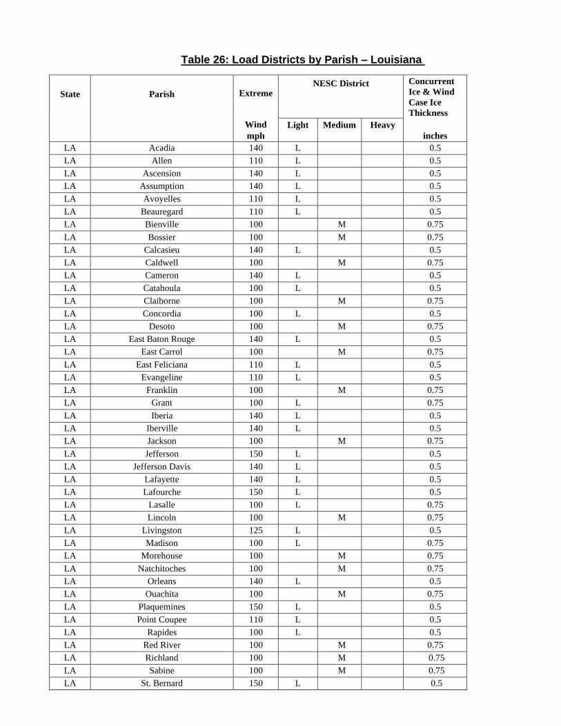
Table 26: Load Districts by Parish – Louisiana
State
Parish
Extreme NESC District Concurrent
Ice & Wind
Case Ice
Thickness
Wind Light Medium Heavy
mph inches
LA Acadia 140 L 0.5
LA Allen 110 L 0.5
LA Ascension 140 L 0.5
LA Assumption 140 L 0.5
LA Avoyelles 110 L 0.5
LA Beauregard 110 L 0.5
LA Bienville 100 M 0.75
LA Bossier 100 M 0.75
LA Calcasieu 140 L 0.5
LA Caldwell 100 M 0.75
LA Cameron 140 L 0.5
LA Catahoula 100 L 0.5
LA Claiborne 100 M 0.75
LA Concordia 100 L 0.5
LA Desoto 100 M 0.75
LA East Baton Rouge 140 L 0.5
LA East Carrol 100 M 0.75
LA East Feliciana 110 L 0.5
LA Evangeline 110 L 0.5
LA Franklin 100 M 0.75
LA Grant 100 L 0.75
LA Iberia 140 L 0.5
LA Iberville 140 L 0.5
LA Jackson 100 M 0.75
LA Jefferson 150 L 0.5
LA Jefferson Davis 140 L 0.5
LA Lafayette 140 L 0.5
LA Lafourche 150 L 0.5
LA Lasalle 100 L 0.75
LA Lincoln 100 M 0.75
LA Livingston 125 L 0.5
LA Madison 100 L 0.75
LA Morehouse 100 M 0.75
LA Natchitoches 100 M 0.75
LA Orleans 140 L 0.5
LA Ouachita 100 M 0.75
LA Plaquemines 150 L 0.5
LA Point Coupee 110 L 0.5
LA Rapides 100 L 0.5
LA Red River 100 M 0.75
LA Richland 100 M 0.75
LA Sabine 100 M 0.75
LA St. Bernard 150 L 0.5


State
Parish
Extreme NESC District Concurrent
Ice & Wind
Case Ice
Thickness
Wind Light Medium Heavy
mph inches
LA St. Charles 140 L 0.5
LA St. Helena 110 L 0.5
LA St. James 140 L 0. 5
LA St. John the Baptist 140 L 0.5
LA St. Landry 110 L 0.5
LA St. Martin, North 140 L 0.5
LA St. Martin, South 140 L 0.5
LA St. Mary 140 L 0.5
LA St. Tammany 140 L 0.5
LA Tangipahoa 125 L 0.5
LA Tensas 100 L 0.5
LA Terrebonne 150 L 0.5
LA Union 100 M 0.75
LA Vermillion 140 L 0.5
LA Vernon 100 L 0.5
LA Washington 125 L 0.5
LA Webster 100 M 0.75
LA West Baton Rouge 140 L 0.5
LA West Carrol 100 M 0.75
LA West Feliciana 110 L 0.5
LA Winn 100 M 0.75

Table 27: Load Districts by County – Mississippi
State
County
Extreme NESC District Concurrent Ice
& Wind Case
Ice Thickness
Wind Light Medium Heavy
mph inches
MS Adams 100 L 0.5
MS Amite 110 L 0.5
MS Attala 100 L 0.5
MS Benton 100 M 1
MS Bolivar 100 M 1
MS Calhoun 100 M 1
MS Carrol 100 M 1
MS Chickasaw 100 M 1
MS Choctaw 100 M 1
MS Claiborne 100 L 0.5
MS Clay 100 M 1
MS Coahoma 100 M 1
MS Copiah 100 L 0.5
MS Covington 110 L 0.5
MS Desoto 100 M 1
MS Franklin 100 L 0.5
MS Grenada 100 M 1
MS Hinds 100 L 0.5
MS Holmes 100 M 1
MS Humphreys 100 M 1
MS Issaquena 100 L 1
MS Jefferson 100 L 0.5
MS Jefferson Davis 110 L 0.5
MS Lafayette 100 M 1
MS Lawrence 110 L 0.5
MS Leake 100 L 0.5
MS Leflore 100 M 1
MS Lincoln 110 L 0.5
MS Madison 100 L 0.5
MS Marion 110 L 0.5
MS Marshall 100 M 1
MS Montgomery 100 M 1
MS Neshoba 100 L 0.5
MS Newton 100 L 0.5
MS Panola 100 M 1
MS Pike 110 L 0.5
MS Ponotoc 100 M 1
MS Quitman 100 M 1
MS Rankin 100 L 0.5
MS Scott 100 L 0.5
MS Sharkey 100 L 0.75
MS Simpson 100 L 0.5
MS Smith 110 L 0.5

State
County
Extreme NESC District Concurrent Ice
& Wind Case
Ice Thickness
Wind Light Medium Heavy
mph inches
MS Sunflower 100 M 1
MS Tallahatchie 100 M 1
MS Tate 100 M 1
MS Tippah 100 M 1
MS Tunica 100 M 1
MS Union 100 M 1
MS Walthall 110 L 0.5
MS Warren 100 L 0.5
MS Washington 100 M 1
MS Webster 100 M 1
MS Wilkinson 110 L 0.5
MS Winston 100 L 0.5
MS Yalobusha 100 M 1
MS Yazoo 100 L 0.75

PROPRIETARY AND CONFIDENTIAL INFORMATION
Page 55 of 85
Table 28: Load Districts by County – Texas
State
County
Extreme NESC District Concurrent
Ice & Wind
Case Ice
Thickness
Wind Light Medium Heavy
mph inches
TX Angelina 100 M 0.75
TX Brazos 100 M 0.75
TX Burleson 100 M 0.5
TX Chambers 140 L 0.5
TX Galveston 140 L 0.5
TX Grimes 100 M 0.75
TX Hardin 125 L 0.5
TX Harris 125 L 0.5
TX Houston 100 M 0.75
TX Jasper 125 M 0.5
TX Jefferson 140 L 0.5
TX Leon 100 M 0.75
TX Liberty 125 L 0.5
TX Limestone 100 M 0.75
TX Madison 100 M 0.75
TX Montgomery 110 M 0.5
TX Nacoqdoches 100 M 0.75
TX Newton 125 M 0.5
TX Orange 140 L 0.5
TX Polk 110 M 0.75
TX Robertson 100 M 0.75
TX Sabine 100 M 0.75
TX San Augustine 100 M 0.75
TX San Jacinto 100 M 0.75
TX Trinity 100 M 0.75
TX Tyler 110 M 0.75
TX Walker 100 M 0.75
TX Waller 110 L 0.5
TX Washington 100 L 0.5
8.2.2.2 Load Combinations All substation equipment support structures shall be designed using the load cases in Section 8.2.2.1 and using the provisions and load combinations of ASCE 113. Wire- supporting structures shall be additionally be designed per the National Electric Safety Code (NESC), Construction Grade B.

PROPRIETARY AND CONFIDENTIAL INFORMATION
Page 56 of 85
Structural Analysis Computer aided analysis and design shall include secondary moments from non‐linear effects (p‐delta) for structure stresses. Analysis procedures shall be based on the applicable design document (AISC 360 for steel structural shapes, ASCE 48 for tubular steel structures, ACI 318 for concrete structures, ASCE 10 for lattice structures, the Aluminum Design Manual for aluminum structures, etc.).
Equipment Support Structure Design Transmission line dead ends shall be located outside the substation, with a slack span inside the substation. Structural supports for bus work, switches, and all other equipment shall be designed in compliance with ASCE MOP 113, and IEEE 605. All substation structures, except dead‐end structures, shall be designed and constructed using hot‐rolled, structural steel square, rectangular, or tapered polygonal tubes. The dead-end structures shall be designed using tapered tubular polygonal shapes. Per ASCE 113, polygonal tube structures shall be designed in accordance with ASCE 48. Per ASCE 113, structures designed with other structural shapes shall be designed in accordance with AISC 360.
8.2.4.1 Structure Deflection
a.) For deflection Load Combinations, the deflection extreme wind shall not be determined by using a reduced return period per ASCE 113, Table 3-14. For the Ice with Wind load Combination, the deflection ice thickness shall not be determined by reducing the ice thickness per ASCE 113, Table 3-15.
b.) Structure deflections shall be checked for loading combinations with all load factors equal to 1.1.
c.) The calculated deflections shall not exceed the values listed below.
c.1) Wire-Supporting Structures and Shield Poles
Horizontal deflection of vertical members: 1/100 of height Horizontal deflection of horizontal members: 1/200 of span Vertical deflection of horizontal members: 1/200 of span
c.2) All other Equipment Support Structures
Horizontal deflection of vertical members: 1/200 of height Horizontal deflection of horizontal members: 1/300 of span
Vertical deflection of horizontal members: 1/300 of span
Control House Structural Design The control house shall be designed using the applicable building code as required by the

PROPRIETARY AND CONFIDENTIAL INFORMATION
Page 57 of 85
Authority Having Jurisdiction (AHJ). If no AHJ oversight is required, the International Building Code 2015 edition shall be used for design. Design, fabrication, and erection of structural steel shall meet the requirements of the IBC, AISC Steel Construction Manual (AISC specification and AISC code of standard practice), and the Performance Standard. Structural design shall comply with seismic design and detailing requirements of the IBC, ASCE 7, and AISC 341. It is preferred to have an Engineered/prefabricated and delivered to site precast concrete building. Steel, concrete, and CMU buildings are all acceptable options.
8.2.5.1 Design Loads
a.) Design Loads shall be determined in accordance with IBC assuming a Risk Category III.
b.) Roof dead load: Weight of built‐up roof, roof joists, insulation, structural members, permanent equipment, cable tray fully loaded with cables, lighting, and any other items supported by the roof.
c.) Floor dead load: Weight of AC/DC panels, control/relay panels, batteries, cable termination cabinets, and other electrical equipment supported on the floor.
d.) Roof live load: 40 psf (minimum)
e.) Snow load: Per the applicable building code. 10 psf ground snow load minimum.
f.) Floor live load: 250 psf or a 1,300-pound load concentrated in any 2½ square foot area.
g.) Wind load: Per the applicable building code. 120 mph (minimum)
h.) Seismic: Per the applicable building code.
8.2.5.2 Fall Protection Building shall be constructed to include permanent anchorage points to accommodate personal fall protection systems capable of supporting 5,000 pounds per worker (OSHA defined impact load). For elevated houses, permanent anchorage points shall additionally be included on the walls of the control house adjacent to each exterior door to accommodate personal fall protection systems for use when working on the platform. All anchorage points shall be shown on roof drawings and marked on control house if not easily visible.
8.2.5.3 Roof The roof shall have a minimum slope of ¼” in 12”; designed and constructed as specified by the IBC. Control house shall have a freestanding roof with no interior vertical supports to support the roof ridge beam.
8.2.5.4 Cable Tray Cable tray and other suspended items shall be adequately supported to resist applied loads including, but not limited to, dead load, cable pulling loads, and seismic loads.

PROPRIETARY AND CONFIDENTIAL INFORMATION
Page 58 of 85
The cable tray shall be capable of carrying a uniformly distributed load of 75 lbs/ft in addition to the weight of the cable tray with a safety factor of 2.0 when supported as a simple span.
Foundations Foundation design will incorporate the soil capacity determined from the geotechnical study. Foundation design shall conform to ACI 318 and County and State Codes. Drilled Pier/Shaft and Slab‐type foundations shall be used. Alternative foundation systems may be considered if agreed upon between Buyer and Seller. Ground supported pieces of equipment, such as circuit breakers and transformers, shall be supported by cast‐in‐place reinforced concrete slabs unless otherwise indicated by the geotechnical report. Transformers shall be positively anchored to supporting foundations. Foundations for the equipment support structures (bus supports, switches, etc.) and transmission line dead end structures shall be cast‐in‐place reinforced concrete drilled piers or spread footings, whichever is appropriate based on the subsurface soil information, unless otherwise indicated by the geotechnical report. Anchor bolts for all structures shall be of sufficient length to allow for the use of leveling nuts. The use of grout between the structure base plate and the top of the structure foundation is not required. The control house foundation shall be piers or concrete slab. A cable routing and pulling area will be designed to facilitate connection with the conduit or pre‐cast concrete cable trench entry from the substation and shall be located beneath the termination cabinet(s). Foundation designs shall be in accordance with the following general minimum criteria:
a) Concrete Strength fc = 4,500 psi at 28 days
b) Grout Auger Cast Piling fc = 5,000 psi at 28 days
c) Reinforcing Steel (ASTM A615 Gr 60) fy = 60,000 psi
d) Foundation Loads
a. Structures From structure design calculations
b. Equipment From equipment manufacturer shop drawings or product literature
e) Importance Factor
a. Structures/Foundations ‐ 1.0 for non‐essential facilities
f) Safety factors (foundation reactions shall be service loads)

PROPRIETARY AND CONFIDENTIAL INFORMATION
Page 59 of 85
a. Shallow Foundations – Bearing Capacity 3.0
b. Shallow Foundations – Stability (Overturning, Sliding, and Uplift) 1.5
c. Drilled Piers Not less than 1.5, preferably 2.0
In general, foundations shall extend below the final grade as required by local or state code and the recommendations in the geotechnical report. The geotechnical report shall clearly state the safety factors needed for each site.
8.2.6.1 Foundation Deflection and Rotation Deflection and rotation of drilled pier foundations shall be limited to 0.5 inch of deflection (vertical and horizontal) and 0.5 degrees of rotation due to unfactored (service) loads.
Materials Structural steel shapes, plates, and appurtenances for general use shall conform to ASTM A992 or ASTM A572 grade 50 (wide-flange shape and ASTM A36 (other shapes)). Steel pipes shall conform to ASTM A53 grade B. Structural tubing shall conform to ASTM A500 grade B. Primary connection bolts shall conform to ASTM A325, type 1 or ASTM A490, type 1 with ASTM A194 grade 2H heavy hex nuts and steel washers conforming to ASTM F436 or Compressible-Washer-Type Direct Tension Indicators conforming to ASTM F959. Connection plates shall be ASTM A36 or ASTM A572 grade 50 steel. Steel components for metal wall panels, roof decking, and cold-formed girts and purlins shall conform to the North American specification for design of cold-formed steel structural members (AISI-S100). Welded connections shall be made with welding electrodes with a minimum tensile strength of 70 ksi. Bolted connections shall be made with minimum 5/8 inch diameter ASTM F3125 Grade A325 high strength bolts, and shall typically be fully pre-tensioned Type N connections with threads included in the shear plane, unless noted otherwise. Connections subject to significant stress reversals or as otherwise required by the AISC shall be designed as slip-critical connections. Welding procedures and qualifications for welders shall be in accordance with AWS D1.1 structural steel welding code and AWS D1.3 sheet steel welding code. Welding electrodes shall be as specified by AWS. Preparation of metal surfaces for coating systems shall follow the specifications and standard practices of the SSPC, NACE, and the specific instructions of the coatings manufacturer. All structural steel for exterior use shall be hot dip galvanized steel per ASTM A123 and ASTM 153, unless noted otherwise. All structural bolts shall be galvanized, unless noted otherwise. Steel assemblies shall be safeguarded against embrittlement and warping during hot dip galvanizing per ASTM A143 and ASTM A384. Repair of damaged and uncoated areas of hot-dip galvanized steel shall be per ASTM A780.
Record documents Seller shall provide buyer with structure and foundation detail drawings and supporting

PROPRIETARY AND CONFIDENTIAL INFORMATION
Page 60 of 85
calculations. The drawings shall note all loading criteria used in the design. Foundation details shall note the structure base reactions used in the design. Drawings shall contain appropriate information (e.g. dimensions, materials, weld data, etc.) to allow reanalysis of the structure under future loading conditions.
8.3 Fence & Signage All substations shall have a fence at least eight feet high (seven-foot fabric and one foot of barbed wire). Fences shall consist of chain link fabric, with 3 strands of barbed wire on 45-degree extension arms, with no ground gaps greater than two (2) inches and secure. All steel, including pipe, roll-formed sections, and fittings to be first quality, full weight, "hot-dipped galvanized" as per ASTM-F1234 or ASTM-F1083. The fence fabric shall be aluminum coated steel according to ASTM-A491. Safe step and touch potential of the perimeter fence shall be verified by an IEEE 80 compliant grounding study.
Gates Drive gates shall be equipped with heavy duty drop bars, drop bar keepers, stops, and flip-over latches (as required) to be locked by standard Entergy lock. Hinges shall be heavy duty and shall allow gates to swing either in, or out, or in and out of all gate leaves. Gates shall be operational from both sides of gate. Gates shall clear finished grade by not more than 3". Gate locking mechanism shall be installed with 3/8" diameter case hardened bolts. The nuts on the bolts shall be incapable of being removed, either by using lock nuts, splitting the end of the bolts or by welding the nuts on the bolts.
Signage
A “Danger – High Voltage – Keep Away” sign shall be placed on the exterior of the fence at a maximum spacing of 50 ft. The signs shall be visible and readable from any angle the substation fence can be approached.
9.0 Substation Physical Design Criteria
9.1 Substation Bus System
Bus Systems The bus system consists of the bus conductor, bus insulators and supporting structures, and jumper conductors to equipment and lines. The bus system shall be designed to meet the voltage and continuous current rating requirement, as well as the mechanical requirements for bus design strength and deflection for all cases and conditions. Rigid Bus structures shall be designed per IEEE Standard 605, IEEE Standard 1427 and in compliance with the NESC. The bus work must be designed to withstand all required weather conditions appropriate for the location of the station and withstand all forces due to maximum fault current. Bus dampening shall be accounted for during detailed design and be between 10% and 33%

PROPRIETARY AND CONFIDENTIAL INFORMATION
Page 61 of 85
of the bus conductor weight.
Bus Configuration The layout of the bus design shall minimize the crossing of bus sections and equipment by lines and other station buses. This is to reduce or eliminate possible common mode failures and to permit service work to be performed without having to take additional busses or equipment out of service. The design shall be of the low-profile type using rigid bus in a horizontal (flat) configuration on vertically mounted station post insulators. Hookstick‐operated disconnect switches shall be provided on both sides of all feeder breakers. If so directed, the bus configurations of the substation facilities shall take into account future expansion. The physical layout shall be made so that expansion can be accomplished with the least amount of outage time when required.
Bus Fittings Bus fittings used for rigid bus connections shall consist of welded connectors. Fittings used for stranded conductor shall consist of either bolted, compression or welded types. For incoming lines to the substation DE structure, the use of quadrant clamps is acceptable. In applications where connection to a line surge arrester is required, the use of bolted connectors is preferred to compression connectors due to the potential chance of incorrect installation and bird caging effect on the incoming conductor. If using compression fittings for the incoming transmission line span, the compression tee and dead‐end fittings shall have NEMA 4‐hole or 6‐hole terminal pads for connection of conductor jumpers. Fittings used for conductor jumpers shall be of the bolted, compression, or welded type to a bolted pad. Jumpers shall be designed so that they can be unbolted and removed from equipment for maintenance, repair, or replacement.
Station Layout The collection system shall be identified and marked. This includes all the phases on pad mount transformers, as well as any time the system transitions from underground to over ground or vice versa. An acceptable method of identification is stickers.
Phase Orientation The phasing orientation of the substation shall be A‐B‐C when facing the low side transformer bushing left to right. If the phasing is different for the interconnecting utility, notation shall be added to the drawings detailing the phase rotation. Additionally, all equipment and busses shall be labeled.

PROPRIETARY AND CONFIDENTIAL INFORMATION
Page 62 of 85
9.2 Grounding System High voltage equipment and structures will be connected to a ground grid. All metallic equipment, structures, and fencing will be conducted to the grounding grid of buried conductors and ground rods, as required for personnel safety.
Grounding Design Criteria Grounding system shall be design using field resistivity values obtained from geotechnical studies. Substation ground grid design shall be based upon IEEE Std. 80 and NESC. Parameters to be used in the design, such as fault current magnitude and duration, will come from various studies, such as the Facility Study and other interconnection studies, and relay and protection system evaluation. Seller shall use fault current split factor calculations that consider OHGW, OPGW and feeder neutral grounding, in order to lower the effective ground fault current. The substation ground grid shall be connected to the overheard transmission line shield wires unless specifically isolated due to other engineering considerations. Clearing time for grounding analysis shall not be shorter than the total time for backup relay operation plus breaker time. The ground grid analysis shall seek to optimize the cost and complexity of the installation. Multiple design iterations shall be developed, considering varying depths of substation rock, grounding conductor size, grid spacing, ground rod depth, etc., until an optimized, lowest‐cost design is achieved. Grounding analysis shall address seasonal conditions as appropriate, such as seasonally dry soil conditions or frozen earth conditions. The ground grid shall be designed to account for the most‐restrictive weather condition. The grounding system shall be modeled using the SES CDEGS grounding analysis software or equivalent.
Grounding System Components
9.2.2.1 Soil Structure: Grounding analysis software shall be used to determine the number of soil layers present based on field test results input. The soil model results are considered usable if the resultant soil model accurately reflects the measured data. The original soil model shall be adjusted to minimize the RMS error.
9.2.2.2 Ground Grid: Ground grid conductor shall be optimized for cost, considering the fault current magnitude and other parameters. Copper clad steel should be considered where appropriate, but soil corrosivity shall be considered when evaluating the use of copper clad steel.

PROPRIETARY AND CONFIDENTIAL INFORMATION
Page 63 of 85
The ground grid shall be installed at a minimum depth of eighteen (18) inches below finished grade (i.e. grade not including any rock cover). Ground grid shall extend to cover the swing access for all man and vehicle gate access points as well as any pad mount transformers and other medium or low voltage station service equipment located close to the substation fence. Recommended to go 3ft beyond the fence or overall equipment/gate offset.
Grounding Rods The standard ground rod shall be 10-foot-long and made of 5/8-inch diameter copper‐clad steel rod. It is acceptable for longer lengths to be made by joining multiple rods together with ground rod couplers. Longer ground rods shall be considered before more costly methods (such as ground wells) are implemented. Ground rods shall be installed at applicable ground grid locations or at locations dictated by design. Applicable locations include substation perimeter, dead‐end structures, lightning masts, surge arrestors, control house corners, etc.
Grounding Connections All underground ground grid cable‐to‐cable and cable‐to‐ground rod connections shall be made with exothermic connections (Cadweld or equivalent). All above ground grounding connections shall be made with mechanical, bolted, or compression connections.
Above Grade Grounding Provisions The perimeter fence shall be connected to the substation ground grid at each gate post, every corner and along the fence at intervals dictated by design. Grounding of the fence shall also include grounding provisions for the fence fabric and barbed wire. All four corners of the control house shall be connected to the substation ground grid. Two grounding conductors shall be installed the entire length of all pre‐cast concrete cable trench greater than 36 inches wide. For pre‐cast concrete cable trench less than 36 inches wide a single grounding conductor shall be installed. These conductors shall provide a convenient access to the substation ground and shall provide some shielding of control cables from electrostatic interference. They shall be connected to the ground grid at all main grid crossings and sized to match the ground grid conductor size. Personnel safety mats (galvanized steel grating) shall be installed on top of the crushed rock surfacing at each disconnect switch operator, manual or motor‐operated gang switches, and each personnel entrance to the control enclosure if metal steps are used. Safety mats shall be bonded to the station ground system in accordance with IEEE 80. Equipment and structure grounds, or “stingers,” consisting of bare conductors shall connect each piece of the substation equipment and steel structure to the ground grid. The minimum conductor size shall be calculated but never be smaller than the ground grid conductor size.
PROPRIETARY AND CONFIDENTIAL INFORMATION
Page 64 of 85
There will be two (2) ground connections to each structure and piece of equipment. Ground studs shall be installed on every breaker bushing pad. Provisions for portable safety ground installations, either bus ≤ 3-inch diameter, ground studs, or grounding stirrups, shall be included at both sides of all disconnect switches. Grounding studs shall be placed such that there is no interference from other equipment (for example, disconnect switch blades).
Crushed Rock The site will be covered with a layer of crushed rock as defined in Section 8.1.6. The crushed rock shall be installed throughout the entire substation area and extend 5 feet beyond the fence and swing radius of the gates. Resistivity tests shall be performed on potential material sources early in the design phase, and those results shall be integrated into the overall grounding system design. The IFC grounding design shall use material with a known, tested resistivity; no assumptions should be made as to the availability of rock of a certain resistivity.
Grounding Drawings The design input from the grounding calculation shall be recorded on the grounding drawing in a concise table. The table shall include all pertinent information, including, but not limited to, final design grid resistivity, depth of crushed rock, rock resistivity, length of ground rods, size of grounding conductor, soil parameters, design fault current, and fault duration. Additionally, it shall be included a field on the grounding drawing for the contractor to record the final fall of potential test results.
9.3 Conduit System All conduit and raceway systems shall comply with NEC and NESC requirements. The conduit and raceway system design shall accommodate power and control cables, communication circuits, underground feeders, and optical fiber cables.
Conduits Low voltage cables used for protection and control or station power shall be placed in conduit wherever they connect to oil immersed equipment to reduce the risk of burning oil flowing in raceways and causing severe damage to cables. All conduit systems including wiring size shall be detailed on drawings. Conduit shall be schedule 40 or greater PVC for below grade or above grade applications. Flexible conduit may be used for transitions where necessary. Galvanized steel conduits shall not be used in below‐grade applications. Conduits shall be sized in accordance with the National Electrical Code (NFPA‐70). Where applicable, 2” and 4” conduits shall be used. Designs shall incorporate one spare conduit per transformer (main GSU) and circuit breakers 138 kV and above. All below‐grade conduits shall be buried to a minimum depth of twenty-four (24) inches

PROPRIETARY AND CONFIDENTIAL INFORMATION
Page 65 of 85
below the finished grade (approximately six inches below the ground grid).The conduit system for the 34.5 kV collector cables shall extend 10 feet beyond the fence and shall be concrete‐encased. Additional coordination shall be made with collector system designer.
Cable Trench For substations and collector facilities that have more than one main GSU transformer, precast concrete trench systems shall be installed. It shall be identified early in detailed design if the current project will ever be expanded with second or third phase. If additional phases are planned, the initial layout shall be designed such that adding new cable trench can be implemented while minimizing impact to existing facilities. Precast concrete trench with a pedestrian strength rating shall be specified for the substation yard raceway system. HS‐20 rated road crossing cable trench shall be used for all vehicle crossing locations. Each vehicle crossing location will be marked with high visibility bollards extending at minimum three (3) feet above the ground and visible during winter snow conditions. Applications for the use of a barrier internal to the cable trench or multiple trench systems may be utilized where required. Conduits shall be provided between the concrete trench system and yard mounted equipment On two transformer stations or an integrated ring bus switchyard, a partial cable trench system is normally required, and provisions shall be provided in detailed design.
Pullboxes Cables entering the control house from the substation yard shall be routed through a pre‐cast cable vault and pulling area into the control house termination cabinet.
Cable Entry and Trays All conduit and cable entry openings into the control house shall be tightly sealed as a barrier to animals to keep out moisture and to minimize heat loss. Cables entering the control house shall be terminated at the appropriate termination cabinet or AC or DC panel board. Inside the control house overhead cable tray suspended from the ceiling shall be used to route cables between the termination cabinet, control and relay panels, and other equipment.
9.4 Lightning System The substation direct lightning stroke shielding design shall be performed in accordance with IEEE Standard 998‐2012 “IEEE Guide for Direct Lightning Stroke Shielding of Substations” using the “electro‐geometrical model” or the “rolling sphere technique”. For small stations it is acceptable to use the fixed angle method as a means for determining proper shield protection locations.

PROPRIETARY AND CONFIDENTIAL INFORMATION
Page 66 of 85
After the substation layout is completed, the direct stroke shielding shall be analyzed to verify that the equipment within the substation fence is adequately protected. The transmission line static wires shall be connected to the substation ground grid. The following criteria shall be used for the lightning shielding design:
• Station BIL, Table 2.
• Lightning stroke density shall be that for the project area as reported by the Fault Analysis and Lightning Location System
• A design failure rate of less than one shielding failure in one hundred (100) years.
The shielding design shall utilize a combination of shield wires, shielding masts and/or mast poles. Shield wires over substation buses shall be arranged such that there is no more than a single bus between shield wire supporting structures. All static wires from the transmission lines shall terminate into the station lightning shielding system.
9.5 Lighting System The primary purpose of substation lighting is to provide sufficient illumination for personnel safety and emergency equipment maintenance. The substation shall be provided sufficient illumination during the night for safe passage of the maintenance crew who might be performing equipment inspection or maintenance. Outdoor lighting is often also intended to deter vandalism; however excessive illumination may attract vandals or result in complaints from the surrounding community. Lighting is also used in certain areas to deter birds from roosting and/or nesting. Yellow color lighting such as sodium vapor does not attract as many bugs, flying bats and birds that in turn attract snakes and climbing animals. Proper placement of lighting is important. Placement of lighting shall consider the collection of insects on adjacent energized equipment. Large quantities of these bugs can attract animals and increase risk of animal outage. At least minimum illumination levels recommended by National Electrical Safety Code C2 shall be provided in generating stations and substations. Illumination levels relevant to substations are as follows:
a) Emergency exit path: 1 foot-candle (11 lux)
b) Control house (occupied): 15 foot-candles (165 lux)
c) Control house (unoccupied): 5 foot-candles (55 lux)
d) Front of switchboards and panels: 15 to 25 foot-candles (165 to 275 lux)
e) Fence: 0.2 foot-candles (2.2 lux)
f) Substation general horizontal: 2 foot-candles (22 lux)

PROPRIETARY AND CONFIDENTIAL INFORMATION
Page 67 of 85
g) Substation vertical (on disconnects etc.) 2 foot-candles (22 lux)
h) Roadway: 0.5 foot-candles (5.5 lux)
i) Open yard: 0.2 foot-candles (2.2 lux)
The need for detailed lighting design for each substation shall be individually evaluated depending upon the substation’s location, site area, type of buswork structures, and the equipment installed in it. LED light fixtures shall be installed for all new installations. The following is required as a minimum for typical substation lighting:
a) The entrance gate into the substation shall be provided with a motion-activated photocell-controlled light.
b) The substation control house entry doors shall be provided with motion activated photocell-controlled lights.
c) The substation shall have switched, photocell-controlled lights, preferably with a timer, for safe passage. The control switch shall be in the control house.
d) A sufficient number of GFCI outlets shall be provided in the substation near the equipment e.g. circuit breakers and power transformers for portable light hookup for night time repairs and maintenance. GFCI outlets provided in the equipment control cabinets shall be used for this function.
9.6 Substation Security/Safety (CODE) Substation Security shall not apply for substations below 161 kV. However, depending of project interconnection area, additional requirements may exist due to other evolving cyber security concerns. Check with Entergy Transmission Planning for site specific concerns.
9.7 Animal Deterrents Means for animal deterrent and mitigation shall be provided in all medium voltage substations, and the MV section of all high voltage substations. IEEE Std 1264 provides guidance in methods and designs to mitigate animal intrusion and resulting interruptions and equipment damage. Animal mitigation shall be achieved by applying substation insulators that have a large enough flashover distance to prevent bridging by animals, such as snakes and squirrels, by increasing phase spacing and by providing guards and covers for insulators or adding barriers between phases to prevent phase to phase bridging by birds. Guards and covers shall be installed on all MV equipment bushings listed below regardless of the spacing. Insulating covers shall be installed on all medium voltage equipment bushings as follows:
a) Power transformers
b) Station service transformers
c) Voltage regulators

PROPRIETARY AND CONFIDENTIAL INFORMATION
Page 68 of 85
d) Circuit breakers and reclosers
e) Surge arresters
f) Capacitors
g) Instrument current and voltage transformers
h) UG cable terminations
i) MV switches and jumpers
Insulators in substations where higher BIL bus and disconnect insulators cannot be applied shall be protected by suitable guards and covers. MV substation equipment including 34.5 kV equipment shall be provided with guards and covers and each phase shall be covered for a distance of three (3) feet, unless otherwise specified during the constructability review. The center phase shall be fully covered. Depending upon location and known animal intrusion problems, additional mitigation may be required.
10.0 Substation Protection & Control Design Criteria
10.1 Protection and Control Requirements The protective relaying shall:
a) Preserve the integrity of the Entergy transmission system by being dependable and secure to the appropriate level of required reliability as specified by Entergy Transmission Planning.
b) Properly coordinate and function with other Entergy relay schemes, and neighboring utilities.
Backup and Transfer Trip Breaker Failure Backup and/or transfer trip circuits to interface with other stations shall always be provided.
Transmission Line Protection Transmission line protective relay equipment at the collector substation shall be provided to meet the requirements of ELL Transmission (as the host utility). HV transmission lines shall have a dual primary line protection scheme comprising of dual primary communication assisted tripping relaying scheme. Each primary protection scheme shall utilize separate instrument current transformers, or separate current transformer cores of a free-standing current transformer, separate CVT or PT secondary windings, and separated dc and ac supplies from a common distribution panel. Breaker Control is typically on the same line panel.
Bus Protection HV and MV bus shall use single low or high impedance protection scheme. Low impedance

PROPRIETARY AND CONFIDENTIAL INFORMATION
Page 69 of 85
is preferred. If using high impedance protection, all of the current transformers in the circuit shall have the same ratio and must be tapped at the full ratio.
Transformer Protection Each power transformer shall be protected by a minimum of one and, preferably, two differential relaying schemes. The transformer differential relay shall be connected to the transformer high side bushing current transformers. Low-side circuit breaker or transformer bushing current transformers shall be positioned to provide a sufficient area of overlap between adjacent protective zones. Protection zones shall be created to prevent through-bus interruption for transformer differential operation. Back up time overcurrent transformer overload relaying shall be provided. Reverse power relaying and/or undervoltage relaying may be required if back feed possibilities exist. Generator Step-up Transformers shall be purchased and supplied with the following integral monitoring devices:
a) Oil level gauge on tank wall or conservator.
b) Pressure relief device(s). The pressure relief device is used for alarms. Transformer tanks containing more than 10,000 gallons of oil shall be provided with two pressure relief devices mounted on diagonally opposite corners of the transformer tank. The device(s) shall be located remote from the control cabinet(s),. Pressure relief value shall be stamped on the device.
a.) Sudden pressure rise relays. Transformers are specified to have two sudden pressure relays used to trip the transformer when both relays have operated. A sudden pressure or Bucholtz relay (Device 63) shall be provided, including seal-in contacts in an enclosure with a threaded conduit hub and “loss of DC indication”
c)
d) Gas accumulation detecting relay (conservator tank units). Contacts of the gas accumulation detecting relay are used for alarm.
e) Temperature monitoring system to indicate top oil and winding temperatures. Seller shall design the system so as not to trip and isolate transformers due to the operation of pressure relief devices, high oil temperature, and high winding temperatures. Main Power Transformer shall be tripped and isolated when the oil level in the transformer tank falls below the critical level to prevent internal flashovers. Main Power Transformers shall have critical oil level as an alarming feature only and no tripping.
Capacitor Bank Protection See IEEE Std C37.99 Guide for Protection of Shunt Capacitor Banks for detailed guidance on the capacitor bank protection schemes. Seller shall employ Unbalance Detection scheme for the protection of the capacitor bank. The aim of this scheme is to trip the capacitor bank if there are unbalances in the phases that result in voltages 110% or more across the individual capacitor unit.
PROPRIETARY AND CONFIDENTIAL INFORMATION
Page 70 of 85
Shunt Reactor Protection See IEEE Std C37.109 for guidance on the protection of shunt reactors. Studies shall be conducted to determine if snubbers are required for reactor switching. Surge arresters are recommended for all reactor applications.
HV Breaker Control Gas insulated circuit breakers are specified to be equipped with two or more stages of gas pressure/density monitoring contacts.
a) Contact of the first stage closes on falling pressure at approximately 10% loss of pressure, and
b) Contact of the second stage closes on falling pressure at a further 10% reduction of gas pressure.
Most manufacturers comply with these requirements except that the first stage and second stage contacts may not necessarily close at 10% loss of pressure for all makes and models of the circuit breakers. A circuit breaker retains its full electrical and mechanical rating at this second stage pressure/density of gas in the circuit breaker. However, the circuit breaker manufacturer will not guarantee any rating below this pressure and, accordingly, the circuit breaker operation shall be disabled below this pressure. The manufacturers of circuit breakers generally do not offer any specific recommendations for the circuit breaker’s continued operation when the second stage contacts of the gas density monitor close. It will be the responsibility of Buyer to determine whether a circuit breaker should be tripped (if it was already closed) or block any close/open operation under these conditions. Since the system security, substation importance, and the circuit breaker applications within the substation vary throughout the system, a common system wide approach on whether to trip or block operation of all circuit breakers cannot be specified. The following is a recommended plan of action, keeping in mind that the circuit breaker retains full rated values at the second alarm stage, and it is capable of withstanding normal system voltage with the gas in the interrupters at atmospheric pressure. Under ideal conditions and with a standard 0.5% gas leakage rate it would take more than five years for any alarm stage to be generated for most breakers. A second stage alarm usually signifies a rapid loss of gas. The circuit breaker control scheme shall address the loss of gas alarms as follows:
1. First Stage Alarm: Effort shall be made to investigate the cause within eight hours (or the next day at the latest).
PROPRIETARY AND CONFIDENTIAL INFORMATION
Page 71 of 85
2. Second Stage Alarm received within one day of receiving the first stage alarm: In locations where the system continuity can be maintained (ring bus, or breaker and half bus substations) the circuit breaker shall be tripped immediately. If the system continuity cannot be maintained, then the circuit breaker operation shall be blocked. In substations with a single bus the circuit breaker operation shall be blocked. It may be necessary to include timers in the relay scheme to achieve this requirement. This should be evaluated during detail design.
3. Second stage alarm received more than one day after receiving the first stage alarm: Block circuit breaker operation
All HV Breaker Control relays shall include LOR (lockout relays).
HV Motor Operated Switch Control When HV motor operated switches (MOS) are used, if a control building is used, it is preferred that the MOS controls be located on the applicable line protection, transformer protection, or breaker control panel. If no control house is required, the panel design must be modified to fit in a suitable NEMA type 4X stainless steel outdoor enclosure.
MV Collection Feeder Protection Primary feeder protection will be provided by an SEL-351S or similar relay at each feeder breaker. Instantaneous and time overcurrent phase and residual ground are typical elements to protect the feeder section. Additional voltage and frequency elements will be enabled to ensure compliance with PRC 024 & PRC 019 (if apply). Breaker failure initiate will be enabled to ensure coordination with MV bus and transformer differential if a breaker fail occurs.
10.2 Relay Calculations and Setting Requirements For relay settings, refer to TE-SD-AD-007 (Relay Settings Procedure) and PM1804 (Transmission Line Relay Setting Criteria, Design and Operation Guide) for guidance. Typical Relay Engineering Calculations:
• Battery Bank Sizing & Design: IEEE-485 & NEC – Article 480.
• Battery Charger Sizing: EPRI Stationary Battery Guide (Design, Application, and Maintenance)
• DC Load Center Sizing: Requires building DC loading table (Watts / Amps) for yard and enclosure (panel) equipment – Nameplate information and/or equipment manuals required.
• AC Load Center Sizing: Requires building AC loading table (Watts / Amps) for yard and enclosure (panel) equipment – Nameplate information and/or equipment manuals required.

PROPRIETARY AND CONFIDENTIAL INFORMATION
Page 72 of 85
• Station Service Sizing
• Voltage Drop Calculations (Use as Guide only): NEC: 215.2(A)(4)
• Conductor Ampacity Calculations (Use as Guide only): NEC Table(s) 310.15 (Engineer to select correct table for use)
• Grounding Methods for Electrical Supply: NESC Sec. 9
• Size of Equipment Grounding Conductors (Use as a Guide only): NEC Sec. 250.122 and Table 250.122.
• Cable in Conduit Fill Calculations: NEC Tables 310.15(B)(2)(a) & 310.15(B)(3)(a), Chapter 9, Table 1, Table 4
• Cable Tray Fill Calculations: NEC 392.22, Table 392.22(A).
10.3 Control House The control house shall be designed to comply with the latest version of the IBC, and with local building code requirements. See Section 7.14. It is preferred to have an Engineered/prefabricated and delivered to site precast concrete building. Steel, concrete and CMU buildings are all acceptable options. The control enclosure shall contain Vendor‐provided station services such as primary and backup AC supply disconnects, an automatic AC transfer switch, AC Load Centers, DC power system and storage battery, and air conditioning units. The Vendor shall be capable of meeting any state‐specific certification and/or inspection requirements. The control enclosure shall be suitable for placement upon both concrete slab and concrete pier foundation types. An indication of design loads for both foundation types shall be supplied with the Vendor’s engineering documentation. All Vendor‐supplied equipment within the control enclosure shall use equipment enclosures conformant to at least the NEMA 1 specification. External equipment shall be appropriately rated and weatherproofed for exterior installation. The control enclosure shall contain space for equipment including:
a) Control enclosure shall be sized to account for all necessary equipment in the station ultimate configuration. No more than sixteen 27‐inch, free‐standing relaying and control panels in a single row. All cable access to the panels will be from a cable tray system above the panels.
b) One wall‐mounted termination cabinet having dimensions of up to 72” x 90” x 24”.
c) Communications equipment including fiber‐optic, telecommunications, and related interfacing gear.
d) Separated control room is required to all projects.
e) The control enclosure shall have a minimum internal ceiling height of 10’‐0” to allow

PROPRIETARY AND CONFIDENTIAL INFORMATION
Page 73 of 85
for adequate equipment clearance below the cable tray. Wall space shall be left open to the greatest extent practical. Conduit and raceway provided by Vendor for building services and included equipment shall be placed at or near the ceiling with vertical service drops. Horizontal raceways and conduits between adjacent equipment such as load centers are acceptable. The control enclosure shall include one eye‐wash system with two saline cartridges when there isn’t water brought to the site.
10.4 DC System One (1) VLA 125 VDC battery system shall be provided along with (2) 130 VDC battery chargers. The batteries and chargers shall be size in accordance of IEEE 485 and considering substation ultimate configuration (if any). The calculation shall consider worst case tripping scenario along with dual trip coil operation. The chargers shall be able to charge within eight to twelve hours. Dual DC Load Centers shall be provided within the control house. DC load centers shall be designed with enough circuit positions for the substation’s ultimate configuration. Each DC load center shall be rated 125 VDC and shall have a main circuit breaker. The DC load centers breaker position and total circuits requirement shall be dictated by final approved DC Calculation considering ultimate substation configuration. DC load centers shall be dead‐front design, installed on the control enclosure wall, and provided with conduit access to the cable tray. Battery chargers shall not have an alarm on/off switch. Each battery charger installed in the station shall alarm on zero current output. Dual charger setups shall be wired for parallel operation. When properly set up each charger shall share half of the battery bank charging current. Battery banks shall be located in a separate room of the control house. There shall be enough space so field personnel can reach each cell and battery terminals for testing and maintenance. A minimum of 24 inches height separation between battery racks is needed to accomplish this. Battery DC grounds shall be monitored via indicating lights on the front panel of the battery charger and indication of a DC ground shall be an input to the station RTU. Battery voltage shall be an input to the station RTU.
10.5 AC System The substation will be equipped with normal and backup AC station service sources supplying 120/240 VAC, 3‐wire, single phase power. Station service is preferred to be provided by low‐ side SSVT, local distribution, or on‐site generator in that order. The design shall include two (2) fused disconnect switches for the incoming feeds (secondary feed of the SSVT and emergency feed). The system neutral must be bonded to ground in one and

PROPRIETARY AND CONFIDENTIAL INFORMATION
Page 74 of 85
only one of the fused disconnects. These two disconnects shall both be in the control building. The normal station power source also needs to have a fused disconnect switch below the station service transformer. The fuses shall be Type LPN. Also, the unprotected conductors between the normal or backup station service transformers and the first disconnect cannot be routed in the same conduit with feeders or branch circuits. There shall be specified an automatic transfer switch (ATS) with microprocessor control. The ATS shall be equipped with alarms for loss of normal service and loss of backup service. The ATS shall be capable of managing a standby generator on the backup source. The ATS shall have neutral bonding provisions. There shall be specified AC load centers with enough circuit positions for the substation’s ultimate configuration. Each AC Load Center shall be 120/240 VAC, three‐wire, single phase, having a 100% rated, main breaker. The final AC load center breaker position and total circuits shall be dictated by final approved AC Calculation considering ultimate substation configuration. AC Load Centers shall be dead‐front design, installed on the control building wall, and provided with conduit or wireway access to the cable tray for use by Others. The load centers shall use a commonly available circuit breaker type.
10.6 Metering Requirements The metering panel shall be designed and constructed as specified in GIA or project planning phases. Multi-conductor cables no smaller than #10 AWG shall be used to connect the instrument transformer secondary windings to the meter location. Under no circumstances shall CT cables contain splices. Larger conductor size may be required depending on the location of instrument transformers in relation to the meters. Seller shall perform burden calculations to determine appropriate conductor size. Conductor used for grounding the metering instrument transformer tank shall be the same size as that used for the ground grid and in no case be smaller than #4/0 AWG. Metering CTs and PTs shall be 0.15B1.8 sized so that tapping down is not required and 3% extended range TR=2 respectively. All meters shall conform to ANSI Standards C12.20, C12.1, and C12.10. Acceptable meters are Landis and Gyr E850 MAXsys Elite, SEL-734 or SEL-735.
10.7 SCADA A Remote Terminal Unit (RTU) and/or gateway device shall be specified, and installed to provide supervisory control, status indication, alarm monitoring, and to gather accumulated and instantaneous data to be telemetered to Entergy Distribution Operations Center (DOC), Transmission Center (TCC) and Entergy Local Balancing Authority (LBA). The RTU shall comply with all GIA requirements.
PROPRIETARY AND CONFIDENTIAL INFORMATION
Page 75 of 85
While all substations require a TCC / DOC RTU to be present, some existing substations host a “dual-port” RTU design in which data is provided to a TCC and LBA SCADA host. Confirmation of existing substation RTU-SCADA host configuration shall be done by contacting the IT-OT EMCS SCADA teams and/or IT-OT Substation Services. Substations that serve as a generation interconnection or system tie boundary with another utility may also require a dual-port RTU-SCADA host configuration. Relay Design Personnel shall perform the following activities per TMM TE-SD-AD-006; RTU/Communication Processor Configuration and Edit Sheet Procedure.
a) Obtain Initial baseline TOC RTU Edit Sheet from IT OP- Tech Personnel of what the SCADA Host has programmed to date of the request, or latest revision if there are revisions being documented.
b) Provide SOC and/or GMS personnel needed information for them to provide new updated SOC and/or GMS edit sheets.
c) Issue final approved TCC, SOC, and/or GMS edit sheets with relay design package.
10.8 Communications The communications media (pilot wire, fiber optic cable, power line carrier or digital microwave) required, and the communications system for supervisory control, telemetering and equipment status indication will generally be known at the project initiation stage. Note that Entergy will usually consider digital microwave as adequate communication media. This will vary depending of the interconnection substation communication capabilities and GIA requirements. Designers of communication circuits shall consider redundant, dual-purpose paths. A telephone is required to facilitate voice receipt of switching orders, emergency services, and restoration of service during outages. For fiber optic cable facilities, two conduits from the substation fence to the fiber optic cable terminal board in the control building shall be furnished and installed. The fiber optic cable between the fence and the terminal board shall be installed in conduit(s). Multiplexers used for fiber-optic interface for digital relay communications schemes system protection shall be hardened per IEEE Std 1613; Standard Environmental and Testing Requirements for Communications Networking Devices Installed in Electric Power Substations, and compatible with IEEE Std C37.94; Standard for N Times 64 Kilobit Per Second Optical Fiber Interfaces Between Teleprotection and Multiplexer Equipment.
10.9 Digital Fault Recorder (DFR) If project requires DFR, TESLA 4000 or similar DFR may be used. This shall include enough current and voltage inputs as per project design.

PROPRIETARY AND CONFIDENTIAL INFORMATION
Page 76 of 85
10.10 Low Voltage Cable (Wiring) The following is a partial list of the requirements for station power, instrumentation and control cabling within the substation.
• The voltage drop for all control cables shall be verified not to exceed 10%.
• All current carrying control cables shall be sized based on the anticipated maximum load currents. Factors that shall be considered to determine the adequate cable size are conductor material, ambient conditions, cable insulation, cable stranding, proximity of parallel current carrying cables and whether the cables are in conduit, in a cable tray or suspended in the air.
• All low voltage power, instrumentation and control cables within the substation shall be insulated for a 600-volt rating.
• Coaxial and instrumentation cable shall be fully shielded both inside and outside the control house.
• All other control cables inside the control house are not required to be shielded.
• Shielded cables shall be required in 345 kV yards and above (CT, Trip and Control Circuits) and in 69 kV and above capacitor banks (grounded and ungrounded). All control and low voltage power cables outside the control house shall have a longitudinally corrugated copper tape shield.
• Returns for power, currents, potentials, controls, analogs and others shall be within the same cable.
• Cable shields and unused conductors are not required to be terminated or grounded for cables within the control house. For shielded field cables, the shield shall be terminated at one end, preferably within the termination cabinet, and unused conductors shall be left ungrounded. The termination cabinet ground bar shall be sized to accommodate shield grounding.
• Analog connections shall be made with 2‐pair #18 AWG instrumentation cable, communication connections shall use shielded 4/C #18 AWG control cable, and status point connections shall use shielded 8/C #18 AWG control cable when new cables are required.
• Power line carrier signals shall be shielded via a shielded coaxial type cable.
11.0 Physical and Electronic Security Refer to IEEE Std. 1402 Guide for Electric Power Substation Physical and Electronic Security for guidance in providing physical and electronic security for the substation. Additional security design elements may be required by NERC Critical Infrastructure Protection (CIP) standards.
The following NERC CIP standards provide mandatory security requirements:
a) CIP-002; Cyber Security-BES Cyber System Categorization
b) CIP-005; Cyber Security-Electronic security Perimeter(s)
c) CIP-006; Cyber Security-Physical Security of BES Cyber Systems

PROPRIETARY AND CONFIDENTIAL INFORMATION
Page 77 of 85
d) CIP-014; Physical Security Critical Substations are designated as Critical or CODE. CODE substations include the Critical Asset and infrastructure but also the larger assets which if destroyed, damaged degraded or otherwise rendered unavailable would have a significant impact on the Bulk Electric System (BES) affecting its stability or ability to transport large loads or would have a detrimental impact on the reliability or operability of the electric grid or would cause significant risk to the public health and safety.
NERC standard CIP-014-1 provides the following criteria for critical designation:
a) All 500 kV substations
b) Substations operating at 200 kV to 499 kV with an aggregate weight exceeding 3000 per table below
c) Substations operating at 200 kV and above and connected to three or more substations with an aggregate weight exceeding 3000 per table below:
Voltage of Line Weight Value per Line
200 kV to 299 KV
700
300 kV to 499 kV
1300
In general, all 500 kV substations, all substations with four 230 kV lines or all substations with three 230 kV and several 161 kV or lower transmission lines may be considered as CODE. The criteria noted above are the minimum threshold for CODE designation. A substation may also be designated CODE as necessary per the unique risks that justify. Refer to SL0801 for further guidance in provision of security for these substations. Substations that are designated as Critical or Deemed Essential (CODE) assets require additional physical and electronic security from physical and electronic intrusion, vandalism as required by NERC CIP-002, -005, and -006. Additional requirements may exist due to other evolving cyber security concerns. Check with Transmission Planning for site specific concerns.
12.0 Deliverables In addition to any submittals and deliverables defined in the contract documents, in

PROPRIETARY AND CONFIDENTIAL INFORMATION
Page 78 of 85
accordance with NERC reliability standards, Seller shall provide the following documentation to Buyer thirty (30) days prior to initial synchronization of the Project, along with any other documentation reasonably requested by Buyer or required by NERC or the Performance Standard:
• BAL-005 – One-line diagram that displays the Electrical Interconnection Point (and includes unique line identifiers/names ensuring that the Project Site and ELL Transmission use the same naming convention when referring to the PV Plant (e.g., breakers, lines, etc.) by Seller
• COM-002 – Network diagram of voice and data links by Seller
• FAC-008 – Identification of most limiting equipment factor based on application of Generator Buyers Facility Rating Methodology by Seller
• MOD-010 – Static Modeling Data of equipment, as applicable, by Seller
• MOD-012 – Dynamic Modeling Data of equipment, as applicable, by Seller
• VAR-002 - Transformer information, including the following, as applicable, by Seller and Buyer (or its Affiliate), and as obtained by Seller from the Approved Vendor of the GSU:
o Tap Settings
o Available fixed tap ranges
o Impedance data
o The + / - voltage range with step-change in % for load-tap changing transformers.
13.0 Attachments
1. ATTACHMENT 1: APPROVED MANUFACTURER LIST* *The Scope Book provides an Approved Vendor List. This Approved Vendor List is in addition to that found in the Scope Book and is considered acceptable for use, and actually preferred.
2. ATTACHMENT 2: SITE ENVIRONMENTAL CHARACTERISTICS

PROPRIETARY AND CONFIDENTIAL INFORMATION
Page 79 of 85
Attachment 1
– Approved Manufacturer List

PROPRIETARY AND CONFIDENTIAL INFORMATION
Page 80 of 85
Purchase Spec. Class Description Qualifier Approved Manufacturer(s) ( )-Preferred Preferred Supplier Type Notes
SA0102 Arresters Arrester, Surge
(Cooper), Siemens, ABB Cooper Substation
PM0201 Battery Batteries & Battery Racks
(Enersys) Nolan Power Relay 125VDC 58 Cell EC-XM/CC-XM only
PM0301 Battery Battery Charger
(Hindel) Nolan Power Relay AT-10 Models
PM0303 Battery Battery Charger Rack
(Enersys) Nolan Power Relay
Bolts Bolts Anchor
Valmont, Distran, Threaded Fasteners
Substation
Bolts Anchor bolt cage for
foundations Valmont, Distran, Threaded Fasteners-w/size limit
Substation
SD0203 Breaker Breaker, EHV 500 & 345kV (Live Tank) (MEPPI), ABB MEPPI Substation
SD0203 Breaker Breaker, EHV 500 & 345kV (Dead Tank) (MEPPI), ABB MEPPI Substation
SD0202 Breaker Breaker, HV, IPO 245kV - 145kV (Siemens), ABB, MEPPI Siemens Substation Per Entergy review
SD0202 Breaker Breaker, HV 245kV - 72.5kV (Siemens), ABB, MEPPI Siemens Substation See table below
SD0201 Breaker Breaker, MV 27kV - 15kV (ABB), MEPPI ABB Substation
SD0201 Breaker Breaker, MV 34.5 kV (ABB) ABB Substation
SB0101 Bus Bus, Aluminum Pipe
(W illiams Metals), AFL (W illiams Metals) Substation
PB0401 Cable, Control Control Cable -Shielded and
Non-Shielded (Southwire), Priority Southwire Relay ICEA Method 1 for color coding
SA0301 Capacitor Bank Capacitor Banks, Shunt
(Cooper), GE, ABB Cooper-Eaton Substation
Capswitcher Capswitcher 170kV - 72.5kV (Southern States) Preferred Sales Substation
Carrier Relays Power line Carrier UPLC Pulsar-Ametek Ametek Relay
PN0201 CCVT CCVT 500kV - 69kV (GE-Alstom), Trench, ABB Crescent Power Relay Polymer only. Trench required when Line trap to be mounted on CCVT.
SD1801 Circuit Switcher Circuit Switcher Series 2000 (S&C) Curtis Stout Substation
Conductor Cable, Aluminum ACSS, ACSR (General Cable), Southwire Aertker Co. Substation
Conductor Copper (Not Control cable)
Copperweld/Alcoa Stuart Irby Substation Grounding conductor
Conductor Cable, Fiber OPT-GW AFL Preferred Sales T-Line
Conductor Cable, Fiber ADSS AFL Preferred Sales T-Line
Conduit Conduit & Accessories
Cantex, Carlon Stuart Irby Substation
Connector Connectors, T-Line ACCR AFL / 3M Preferred Sales T-Line
Connector Connectors, T-Line ACSS AFL Preferred Sales
Connector Connectors line (Fiber, OPGW,
ACSR) Fiber, OPGW, ACSR AFL Preferred Sales T-Line
Connector Connectors, T-Line
Maclean Power Sys Preferred Sales T-Line
Connectors/Fittings Connectors/Fittings -Substation
Anderson, AFL, Homac, Travis, Sefcor, Burndy
Substation
SL0403 Control House Control House Drop-In (turnkey) VFP VFP Relay Concrete only.
SL0403 Control House Control House
Modular Connections, VFP, Atkinson, Trachte,
Oldcastle Substation Concrete only.
PN0301 CT CT Slipover only ITEC, ABB, Meramac, Siemens
Relay
PN0301 CT CT 34.5kV - 15kV ABB, GE
Relay
PN0301 CT CT 500kV - 69kV (GE-Alstom), Trench, ABB Cresent Power Relay Polymer only
DFR DFR (Digital Fault Recorder)
MehtaTech Louisiana, Mississippi,
Arkansas only Relay
DFR DFR (Digital Fault Recorder)
Qualitrol Texas only Relay
Fittings Conductor Fittings
Compression AFL, Secor, Anderson, Hubell Stuart Irby Substation

PROPRIETARY AND CONFIDENTIAL INFORMATION
Page 81 of 85
Purchase Spec. Class Description Qualifier Approved Manufacturer(s) ( )-Preferred Preferred Supplier Type Notes
Grounds Rods Clamps
Ground Rods, Clamps
Cadweld, Erico, Thermoweld Stuart Irby Substation
TA0504 Insulators Insulator, Line, Toughened
Glass Sediver
T-Line
TA0504 Insulators Insulator, Line, Polymer (Polymer Insulator Only) Maclean Power Sys Preferred Sales T-Line
TA0504 Insulators Insulator, Line, Polymer (Polymer Insulator Hardware
Assembly) Maclean Power Sys Preferred Sales T-Line
SA0502 Insulators Insulator, Station Post,
Porcelain 500kV-69kV (Seves), Victor, Lapp,NGK, Newell, Vanguard
Substation
SA0502 Insulators Insulator, Station Post, Polymer 230kV-15kV (Maclean Power Sys)
Substation
Junction Box Junction Boxes
MMR, SEL, Custom Automated, Premier Control
Relay
Meter Meter & Cables Elite Model Landis+Gyr
Relay
CP Approved Panels Appendix S
Panel Panel - Battery Switching
SEL Power Connections Relay
CP Approved Panels
Appendix S Panel Panel - AC & DC Stand Alone
Peterson Electric Panel Peterson Relay No AC/DC Combo Panel permitted
PM3507 Panel Panel - Autoxfmr Differential
MMR, SEL, Custom Automated, Premier Control
Relay
PM3505 Panel Panel - Power xfmr Differential
MMR, SEL, Custom Automated, Premier Control
Relay
PM0501 Panel Panel - Breaker Control
MMR, SEL, Custom Automated, Premier Control
Relay
PM0602 Panel Panel - Bus Differential
MMR, SEL, Custom Automated, Premier Control
Relay
PM1803 Panel Panel - Line, Line/Breaker
MMR, SEL, Custom Automated, Premier Control
Relay
MI0200 Panel Panel - Meter
MMR, SEL, Custom Automated, Premier Control
Relay
Poles Pole Caissons
(Valmont) Preferred Sales T-Line
TC0609 Poles Pole, Concrete
(Valmont) Preferred Sales T-Line
TC0608 Poles Pole, Steel
(Valmont) Preferred Sales T-Line
PN0701 PT PT 34.5kV and below ABB, GE, Trench
Relay
PN0701 PT PT 230kV - 69kV GE-Alstom, Trench, (ABB)
Relay Polymer only
SN0903 Reactor Reactor, Dry Type Shunt Below 230kV Alstom Grid, Coil Innovations, Trench
Substation
SN0902 Reactor Reactor, Current Limiting
Alstom Grid, Coil Innovations, Trench
Substation
SN0904 Reactor Reactor, Oil filled Shunt 230kV, 500kV ABB, Alstom Grid, Mitsubishi, Siemens, SMIT
Substation
SN1002 Regulators Regulator
Pennsylvania Transformers Curtis Stout Substation
Relay Protective Relays & associated
accessories SEL Power Connections Relay
RTU
Accessories & Cables (ACS), GE Grid Solutions Ruffin & Associates Relay
PM3002 RTU RTU SEL RTAC SEL Power Connections Relay

PROPRIETARY AND CONFIDENTIAL INFORMATION
Page 82 of 85
Purchase Spec. Class Description Qualifier Approved Manufacturer(s) ( )-Preferred Preferred Supplier Type Notes
SL1301 Signs
Signs - Entergy Substation Switchyard
Placard w/Address Impco Impco Substation This is the substation name and address sign on the front fence.
SL1301 Signs Signs - General
Stuart Irby Stuart Irby Substation
SC0401, SL0505 Structure Steel Substation, Tubular / Tapered (Distran), Valmont Distran Substation
SC0401, SL0505 Structure Steel Substation, Lattice (Distran), Industrial Steel Distran Substation
SC0401, SL0505 Structure Steel Standard and Tapered
Tubular Substation, pre-existing designs
w/details (Distran), Valmont Distran Substation
PM3401 Switch ATS (Automatic Transfer
Switch) ASCO Utility and Industrial
Supply LLC, WESCO Relay
Switch Switch, T-Line Switch group operated 245kV
and below SEECO Southern Utility Sales
Agency T- Line
SD1502 Switch Switch, Disconnect 500 & 345kV (Southern States), Pascor Atlantic Preferred Sales Substation
SD1501 Switch Switch, Disconnect 230kV - 69kV (Southern States), USCO, Pascor Atlantic Preferred Sales Substation
SD0601 Switch Switch, Disconnect 34.5kV - 15kV (Southern States), USCO Preferred Sales Substation
SD0701 Switch Switch, Disconnect, Hookstick 34.5kV - 15kV (Southern States), USCO Preferred Sales Substation
Switch Switch, Fuse (SMD style) 34.5kV - 15kV (S&C) Curtis Stout Substation
SD1601 Switch/Motor
Operators Motor Operator Southern States (Southern States) Preferred Sales Substation For Southern States switches
SN1101 Transformer SSVT; Station Service Voltage
Transformer 230kV - 69kV Alstom Grid, ABB
Substation Polymer only
SN0103, SN0104 Transformer Transformer, Auto 230kV and Above 100MVA ABB, HICO, MEPPI, Siemens, SMIT, SPX-W aukesha Electric
Substation See chart below
SN0102 Transformer Transformer, Small Auto below 230kV and 100MVA (SPX-W aukesha Electric ), ABB, HICO, Howard Aertker Co. Substation See chart below
SN0801 Transformer Power Transformers 230kV and below (SPX-W aukesha Electric ), ABB, HICO Aertker Co.
See chart below
PM0802 Trap Trap, Line Carrier
Trench (No other supplier approved) Curtis Stout Relay See CCVT note above
Trench Trench (Cable Trench)
(Concast), Trenway, Old Castle GHMR Substation
PM0804 Tuner Tuner, Line Carrier
Trench Curtis Stout Relay
Xfmr Firewall

PROPRIETARY AND CONFIDENTIAL INFORMATION
Page 83 of 85
ENTERGY APPROVED SUBSTATION TRANSFORMER SUPPLIERS TWO-WINDING & AUTO-TRANSFORMERS RATED < 100MVA (3-phase) and HV ≤ 230kV
Production Facility &
Location
Currently qualifying or already
qualified
Maximum ratings approved by Entergy Capabilities reported by facility
MVA (3ø) KV MVA (3ø) KV
ABB / Crystal Springs, MS USA
qualified 50 (MS) 161 (MS) ~60 (MS) 161 (MS)
Delta Star / Lynchburg, VA
qualified 60 230 ~200 230
HICO-Memphis qualified 1000 230 1000 230
Waukesha Electric (SPX), Goldsboro, NC &
Waukesha, WI USA qualified 80 (NC), 100 (WI) 230 (NC), 230 (WI) ~80 (NC), 800 (WI) 230 (NC), 345 (WI)
AUTO-TRANSFORMERS RATED ≥ 100MVA (3-phase) or HV > 230kV
Production Facility & Location
Currently qualifying or already qualified
Maximum ratings approved by Entergy Capabilities reported by facility
MVA (3ø) KV MVA (3ø) KV
ABB / Varennes, Quebec,
Canada; Guarulhos, Brazil; Cordoba, Spain
qualified 1000 (Can), 500 (Br), 800 (Sp) 500 (Can), 500 (Br), 500 (Sp)
1200 (Can), 600 (Br), 800 (Sp) 765 (Can), 765 (Br),
500 (Sp)
HICO-Memphis qualified 1000 765 1000 765
Mitsubishi / Ako,
Japan qualified ~1000 500 ~1500 1000+
Siemens / Linz & Weiz, Austria; Nuremburg,
Germany; Jundiai, Brazil; Bogota, Colombia qualified
1000 (Aus, Ger), 750 (Br), 200 (Col)
500 (Aus, Ger, Br), 230 (Col)
2000 (Aus), 1100 (Ger), 1000 (Br), 250 (Col)
765 (Aus), 1000+ (Ger), 765 (Br), 345
(Col)
SMIT / Nijmegen, Netherlands
qualified ~800 500 ~1200 500
Waukesha Electric (SPX), Waukesha, WI
USA qualified 400 345 ~800 345
ENTERGY APPROVED HV CIRCUIT BREAKER MODEL NUMBERS Voltage Continuous Current
(A) Interrupting Rating (A) Siemens Breaker to be ordered CT Ratio and Accuracy CT Quantity
230 KV 3000 50KA SPS2-245-50-3000 3000:5 C800 3 per bushing
3000 63KA SPS2-245-63-3000(reference) 3000:5 C1200 3 per bushing non-standard
161 KV 3000 40KA SPS2-170-40-3000 3000:5 C800 3 per bushing
3000 63KA SPS2-170-63-3000(reference) 3000:5 C1200 3 per bushing non-standard
138 KV 3000 40KA SPS2-145-40-3000 3000:5 C800 2 per bushing
3000 63KA SPS2-145-63-3000(reference) 3000:5 C1200 2 per bushing non-standard
115 KV 3000 40KA SPS2-145-40-3000 3000:5 C800 2 per bushing
3000 63KA SPS2-145-63-3000(reference) 3000:5 C1200 2 per bushing non-standard
69 KV 3000 40KA SPS2-72.5-40-3000 3000:5 C800 2 per bushing
3000 63KA SPS2-145-63-3000(reference) 3000:5 C1200 2 per bushing non-standard

PROPRIETARY AND CONFIDENTIAL INFORMATION
Page 84 of 85
Attachment 2
Site Environmental Characteristics

PROPRIETARY AND CONFIDENTIAL INFORMATION
Page 85 of 85
Site Environmental Characteristics The Project Site environmental data that Seller shall use for the design of the Collector Substation shall have been determined prior to bid submission. The minimum required Project Site environmental data to be included is shown in Table 2-1 below. This Table 2-1 shall have been completed by Seller and included with the bid. Additional pertinent criteria shall be provided as needed.
Attachment Table 2-1. Project Site Environmental Characteristics
Descriptions Data (Units)
Elevation (substation)
Contamination Level (light, medium, heavy, extra heavy) *
Average Annual Temperature
Average High Temperature
Extreme High Temperature
Average Low Temperature
Extreme Low Temperature
Average Annual Precipitation
Maximum 24-hour Rainfall
Maximum 1-hour Rainfall
Maximum 24-hour Snowfall
Ground Snow Load
Design Ice Load
Design Wind Speed
Isokeraunic Level
Seismic Referenced Code
Mapped Spectral Response Acceleration at Short Period (0.2- Second) SS
Mapped Spectral Response Acceleration at 1-Second Period S1
Site Class
Seismic Design Category
*All equipment external bushing creepage distance shall be based on this criterion. If not available, medium (35mm/kV) shall be used. This factor is applied to nominal line to ground voltage.


![Apparent Power Loss Based Equivalent Model of Wind Farm Collector System · 2018. 12. 8. · are required [3]. Typical wind power plants consist of an interconnected substation, collector](https://static.fdocuments.us/doc/165x107/60bcebbff534bd773c11e89f/apparent-power-loss-based-equivalent-model-of-wind-farm-collector-2018-12-8.jpg)