![Brownsville herald. (Brownsville, Tex.). 1931-01-04 [p ]. · 2020. 10. 14. · gfmmmtmmmmmmmmmmmmmmmrnmm»»*>»»***mmmmmmmmmmmmmmmm..... ..... J| 1 « ----- --—— Brownsville](https://static.fdocuments.us/doc/165x107/611f38f716d6ee6a5426b1ec/brownsville-herald-brownsville-tex-1931-01-04-p-2020-10-14-gfmmmtmmmmmmmmmmmmmmmrnmmmmmmmmmmmmmmmmmm.jpg)
Attachment A Scope of Work - Brownsville Public Utilities ...
17
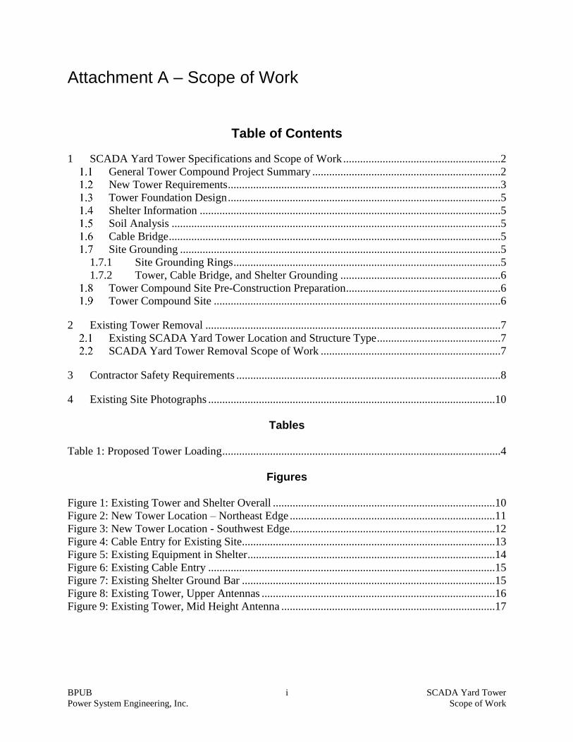
BPUB i SCADA Yard Tower Power System Engineering, Inc. Scope of Work Attachment A – Scope of Work Table of Contents 1 SCADA Yard Tower Specifications and Scope of Work ........................................................2 General Tower Compound Project Summary ...................................................................2 New Tower Requirements .................................................................................................3 Tower Foundation Design .................................................................................................5 Shelter Information ...........................................................................................................5 Soil Analysis .....................................................................................................................5 Cable Bridge ......................................................................................................................5 Site Grounding ..................................................................................................................5 1.7.1 Site Grounding Rings ...............................................................................................5 1.7.2 Tower, Cable Bridge, and Shelter Grounding .........................................................6 Tower Compound Site Pre-Construction Preparation.......................................................6 Tower Compound Site ......................................................................................................6 2 Existing Tower Removal .........................................................................................................7 Existing SCADA Yard Tower Location and Structure Type ............................................7 SCADA Yard Tower Removal Scope of Work ................................................................7 3 Contractor Safety Requirements ..............................................................................................8 4 Existing Site Photographs ......................................................................................................10 Tables Table 1: Proposed Tower Loading...................................................................................................4 Figures Figure 1: Existing Tower and Shelter Overall ...............................................................................10 Figure 2: New Tower Location – Northeast Edge .........................................................................11 Figure 3: New Tower Location - Southwest Edge.........................................................................12 Figure 4: Cable Entry for Existing Site..........................................................................................13 Figure 5: Existing Equipment in Shelter ........................................................................................14 Figure 6: Existing Cable Entry ......................................................................................................15 Figure 7: Existing Shelter Ground Bar ..........................................................................................15 Figure 8: Existing Tower, Upper Antennas ...................................................................................16 Figure 9: Existing Tower, Mid Height Antenna ............................................................................17
Transcript of Attachment A Scope of Work - Brownsville Public Utilities ...
BPUB i SCADA Yard Tower
Power System Engineering, Inc. Scope of Work
Attachment A – Scope of Work
Table of Contents
1 SCADA Yard Tower Specifications and Scope of Work ........................................................2 General Tower Compound Project Summary ...................................................................2
New Tower Requirements .................................................................................................3 Tower Foundation Design .................................................................................................5 Shelter Information ...........................................................................................................5 Soil Analysis .....................................................................................................................5
Cable Bridge ......................................................................................................................5 Site Grounding ..................................................................................................................5
1.7.1 Site Grounding Rings ...............................................................................................5 1.7.2 Tower, Cable Bridge, and Shelter Grounding .........................................................6
Tower Compound Site Pre-Construction Preparation .......................................................6 Tower Compound Site ......................................................................................................6
2 Existing Tower Removal .........................................................................................................7
Existing SCADA Yard Tower Location and Structure Type ............................................7 SCADA Yard Tower Removal Scope of Work ................................................................7
3 Contractor Safety Requirements ..............................................................................................8
4 Existing Site Photographs ......................................................................................................10
Tables
Table 1: Proposed Tower Loading ...................................................................................................4
Figures
Figure 1: Existing Tower and Shelter Overall ...............................................................................10 Figure 2: New Tower Location – Northeast Edge .........................................................................11
Figure 3: New Tower Location - Southwest Edge.........................................................................12 Figure 4: Cable Entry for Existing Site..........................................................................................13
Figure 5: Existing Equipment in Shelter ........................................................................................14 Figure 6: Existing Cable Entry ......................................................................................................15 Figure 7: Existing Shelter Ground Bar ..........................................................................................15 Figure 8: Existing Tower, Upper Antennas ...................................................................................16 Figure 9: Existing Tower, Mid Height Antenna ............................................................................17
BPUB 2 SCADA Yard Tower
Power System Engineering, Inc. Scope of Work
1 SCADA Yard Tower Specifications and Scope of Work
General Tower Compound Project Summary
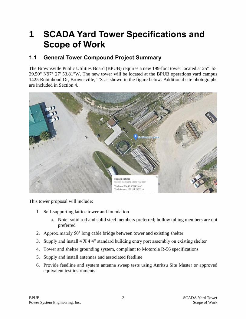
The Brownsville Public Utilities Board (BPUB) requires a new 199-foot tower located at 25° 55'
39.50" N97° 27' 53.81"W. The new tower will be located at the BPUB operations yard campus
1425 Robinhood Dr, Brownsville, TX as shown in the figure below. Additional site photographs
are included in Section 4.
This tower proposal will include:
1. Self-supporting lattice tower and foundation
a. Note: solid rod and solid steel members preferred; hollow tubing members are not
preferred
2. Approximately 50’ long cable bridge between tower and existing shelter
3. Supply and install 4 X 4 4” standard building entry port assembly on existing shelter
4. Tower and shelter grounding system, compliant to Motorola R-56 specifications
5. Supply and install antennas and associated feedline
6. Provide feedline and system antenna sweep tests using Anritsu Site Master or approved
equivalent test instruments

BPUB 3 SCADA Yard Tower
Power System Engineering, Inc. Scope of Work
BPUB is looking for a tower company (Seller) to provide a turnkey installation of the new tower,
antenna, and feedlines. The role of the Seller shall be to provide material and services to deploy
and commission the new tower. All materials shall be provided by the Seller.
Exhibit 1 will provide a recent geotechnical report that the Seller will use for designing the
materials and services for this Project. Please note that this exhibit will be issued as an Addendum
as soon as it becomes available (anticipated January 15, 2021).
Detailed roles of the BPUB and Seller for this Project are provided in the Responsibility Matrix.
Seller shall be responsible for:
• Site preparation.
• Providing the specified tower.
• Designing and installing specified tower foundations.
• Furnishing and installing all associated hardware and appurtenances.
• Performing all planning and installation of the tower.
• Removal of existing 160’ tower after completion of new tower installation and
commissioning
• Site restoration and cleanup.
Seller shall also be responsible for ensuring that the tower and shelter installations meet all design
criteria, labor services, guarantees, and installation requirements contained in these specifications,
or in national or the industry standards referenced in this specification.
BPUB will receive approval for this tower from the Brownsville City Council. BPUB will provide
all NEPA, FCC, and local permitting required for this tower. The Seller will provide FAA filings.
New Tower Requirements
Tower: The tower shall be a 199-foot self-supporting communications tower. The BPUB is
requesting an unlit tower of 199 feet, meaning the overall height of this tower including the
foundation projection is allowed up to 199 feet. No tower attachments, including lightning
protection shall be higher than 199 feet above ground level (AGL).
Materials: Hot-dipped, galvanized steel, or stainless steel. All steel materials used in the
construction of the towers shall be new, and shall conform to the provisions of ANSI/TIA-222 Rev
G and Rev H with respect to physical properties, manufacture, workmanship, and factory finishes.
Tower design documents submitted shall clearly show design parameters matching both
ANSI/TIA-222 RV G & Rev H.
BPUB 4 SCADA Yard Tower
Power System Engineering, Inc. Scope of Work
Climbing Ladder/Pegs: The tower shall include a climbing ladder that begins at 18 feet from the
ground. The ladder shall include an approved safety climb system. The tower shall also have
provisions to prevent climbing by unauthorized persons.
Loads and Stresses: The design of the tower shall take into account dead and live loads induced
by the structure itself and all appurtenances, and all stress applied to the tower and its
appurtenances by wind forces. The minimum safety factors listed on ANSI/TIA-222 Rev G and
ANSI/TIA-222 Rev H , Structure Class III, Exposure Category C shall apply under the most severe
combination of dead load plus live loading.
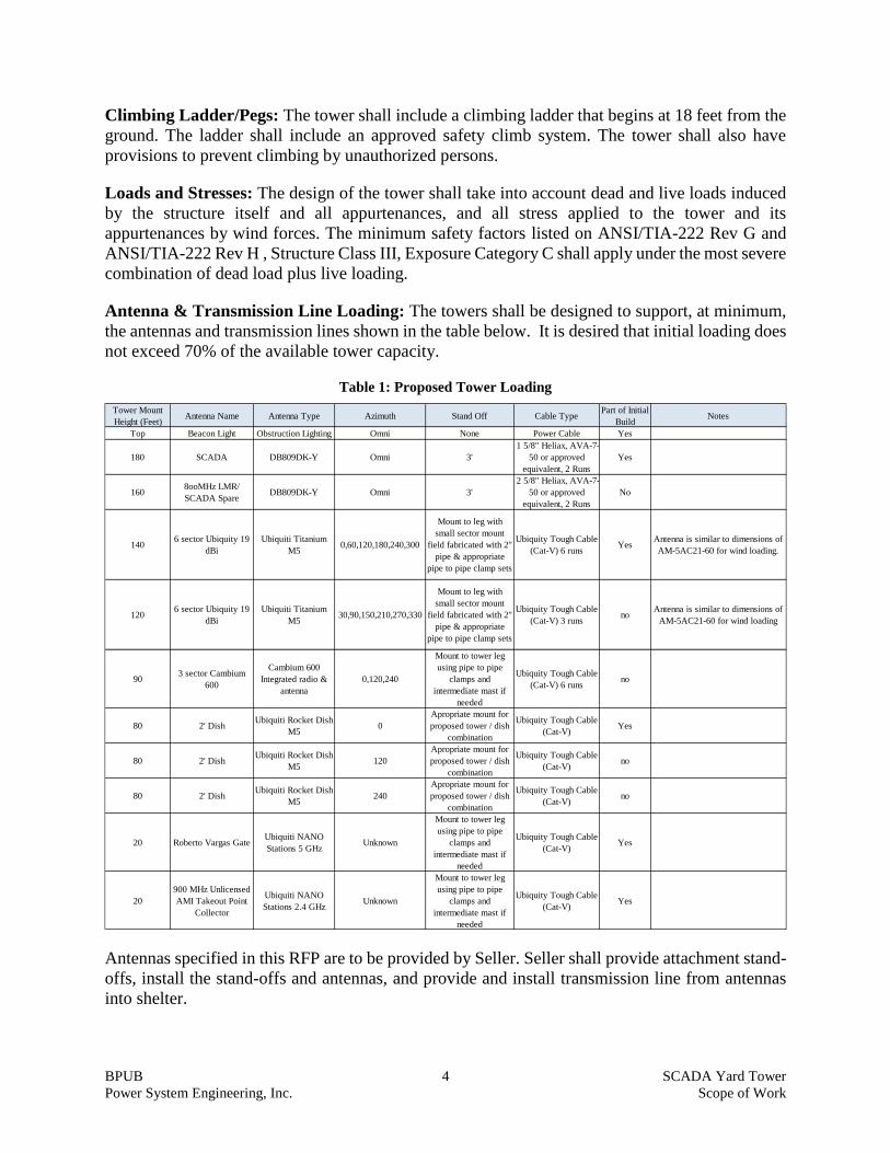
Antenna & Transmission Line Loading: The towers shall be designed to support, at minimum,
the antennas and transmission lines shown in the table below. It is desired that initial loading does
not exceed 70% of the available tower capacity.
Table 1: Proposed Tower Loading
Antennas specified in this RFP are to be provided by Seller. Seller shall provide attachment stand-
offs, install the stand-offs and antennas, and provide and install transmission line from antennas
into shelter.
Tower Mount
Height (Feet)Antenna Name Antenna Type Azimuth Stand Off Cable Type
Part of Initial
BuildNotes
Top Beacon Light Obstruction Lighting Omni None Power Cable Yes
180 SCADA DB809DK-Y Omni 3'
1 5/8" Heliax, AVA-7-
50 or approved
equivalent, 2 Runs
Yes
1608ooMHz LMR/
SCADA SpareDB809DK-Y Omni 3'
2 5/8" Heliax, AVA-7-
50 or approved
equivalent, 2 Runs
No
1406 sector Ubiquity 19
dBi
Ubiquiti Titanium
M50,60,120,180,240,300
Mount to leg with
small sector mount
field fabricated with 2"
pipe & appropriate
pipe to pipe clamp sets
Ubiquity Tough Cable
(Cat-V) 6 runsYes
Antenna is similar to dimensions of
AM-5AC21-60 for wind loading.
1206 sector Ubiquity 19
dBi
Ubiquiti Titanium
M530,90,150,210,270,330
Mount to leg with
small sector mount
field fabricated with 2"
pipe & appropriate
pipe to pipe clamp sets
Ubiquity Tough Cable
(Cat-V) 3 runsno
Antenna is similar to dimensions of
AM-5AC21-60 for wind loading
903 sector Cambium
600
Cambium 600
Integrated radio &
antenna
0,120,240
Mount to tower leg
using pipe to pipe
clamps and
intermediate mast if
needed
Ubiquity Tough Cable
(Cat-V) 6 runsno
80 2' DishUbiquiti Rocket Dish
M50
Apropriate mount for
proposed tower / dish
combination
Ubiquity Tough Cable
(Cat-V)Yes
80 2' DishUbiquiti Rocket Dish
M5120
Apropriate mount for
proposed tower / dish
combination
Ubiquity Tough Cable
(Cat-V)no
80 2' DishUbiquiti Rocket Dish
M5240
Apropriate mount for
proposed tower / dish
combination
Ubiquity Tough Cable
(Cat-V)no
20 Roberto Vargas GateUbiquiti NANO
Stations 5 GHzUnknown
Mount to tower leg
using pipe to pipe
clamps and
intermediate mast if
needed
Ubiquity Tough Cable
(Cat-V)Yes
20
900 MHz Unlicensed
AMI Takeout Point
Collector
Ubiquiti NANO
Stations 2.4 GHzUnknown
Mount to tower leg
using pipe to pipe
clamps and
intermediate mast if
needed
Ubiquity Tough Cable
(Cat-V)Yes
BPUB 5 SCADA Yard Tower
Power System Engineering, Inc. Scope of Work
This installation shall include sweep testing the antennas and cables during the installation and all
cable grounding and bonding as required by BPUB.
Tower Foundation Design
The tower foundation and anchor bolt designs shall be designed to the ANSI/TIA-222-G and
ANSI/TIA-222-H standard. Foundation design documents submitted shall clearly show design
parameters matching both ANSI/TIA-222 Rev G & Rev H. The foundation design shall be based
on the BPUB-provided geotechnical specifications as found in Exhibit 1, which will be issued as
an addendum when it becomes available in January 15, 2021. All concrete loads shall have core
samples taken and tested by the Seller to verify the concrete strength meets the specifications.
Shelter Information
A communications shelter is currently in place near the existing tower. The Seller shall install a
cable bridge cable support assembly between the new tower, and the existing shelter. The Seller
shall install a new entry port assembly on the existing shelter near the current cable entry location
and terminate the cable bridge at this point. The Seller shall install a ground ring around the shelter
in conjunction with the ground ring around the tower. All grounding shall meet Motorola R-56
standards, as well as National Electrical Code (NEC) requirements.
Soil Analysis
Soil geotechnical analysis is being performed by the BPUB. Seller shall use this analysis in the
design of the tower foundations. A copy of the soil report prepared by the geotechnical engineering
firm will be provided as Exhibit 1.
Cable Bridge
The Seller shall provide a cable bridge between the tower and shelter. The cable bridge shall be
approximately 50 feet in length.
Site Grounding
1.7.1 Site Grounding Rings
The ground system shall comply with the Motorola R-56 grounding specification and the National
Electric Code (NEC). This Site requires a tower ring and a shelter ring with the two rings connected
in accordance with the R-56 specification. The ground system shall be installed by Seller but will
be left uncovered until inspected and approved by BPUB or their Authorized Representative. All
below grade ground connections shall be exothermic welds. All above grade connections can be
irreversible compression fittings.
Seller shall measure the ground system resistance using the three-point voltage-drop method and
provide the results as part of the as-built documentation. The resistance measurement shall be
lower than 5.0 Ohms, or the Seller shall remedy prior to backfilling the rings.
BPUB 6 SCADA Yard Tower
Power System Engineering, Inc. Scope of Work
1.7.2 Tower, Cable Bridge, and Shelter Grounding
Once the tower is installed, the Seller shall provide a tower grounding bar at the base of the tower
that connects to the tower ground ring using exothermic welds.
Seller shall provide master ground bars inside and outside of shelter cable entry port and associated
connections to the shelter ground ring in accordance with R-56 standards using exothermic welds.
The cable bridge shall be grounded to both rings using exothermic welds.
All bolted ground lugs on ground busses shall have two-hole lug attachments. All hardware shall
be stainless steel. All grounding installed by the Seller shall be compliant to the Motorola R-56
Grounding standard and the National Electric Code (NEC).
Tower Compound Site Pre-Construction Preparation
The existing site is grass covered flat ground. The new tower will be adjacent to the existing tower
and structure as shown in the pictures in Section 4 below. The site allows for access by digging
equipment for the foundation and access by a crane for tower installation. No additional
preparation is needed.
Tower Compound Site
The area around the tower will be finished with a weed barrier covered by gravel or crushed stone.
Seller shall remove all excess soil and gravel used during the site preparation from the BPUB
property. See photographs in Section 4 for more site information.
BPUB 7 SCADA Yard Tower
Power System Engineering, Inc. Scope of Work
2 Existing Tower Removal
BPUB requests separate pricing for the removal of the existing BPUB-owned SCADA Yard
Tower. The existing tower has been inspected and maintained on a continual basis. As of the last
inspection the existing tower is considered unfit for service.
It is desired that all antenna attachments be removed for future reuse as much as practical.
The existing tower structure is located approximately 75’ from the site of the proposed new tower.
BPUB will provide access as needed for the work.
Existing SCADA Yard Tower Location and Structure Type
City Location: BPUB operations yard campus
Street Address: 1425 Robinhood Dr, Brownsville, TX
GEO Location: Latitude 25° 55' 39.50", Longitude 97° 27' 53.81"W
Ground ASL: Tower base approximated at 30’ above sea level
Type: Unknown Rohn style; Possibly 45 or 55 series
Height: 160 ft. guyed.
Fabricated: Unknown
Operational: Unknown
Registration: None found; Unknown
SCADA Yard Tower Removal Scope of Work
1. Contractor to dismantle the existing tower, including the tower structure and all associated
hardware and remaining fixtures. This includes:
• Guy wires, anchors, and associated hardware
• Any remaining cabling and mounting hardware
• Lamping and associated mounting hardware and wiring
2. Contractor to remove and dispose of all tower structure elements and above listed material.
3. Contractor to excavate, remove, and dispose of all guy wire anchors.
4. Contractor to excavate, remove, and dispose of tower concrete foundation.
5. Contractor to fill any excavations with material approved by BPUB and finish rough grade to
match adjacent grade and finish.
6. BPUB will file appropriate notices with the FCC regarding tower registration and relocation
of applicable frequencies.

BPUB 8 SCADA Yard Tower
Power System Engineering, Inc. Scope of Work
7. Contractor to determine appropriate coordination as required with the FAA, FCC, and other
agencies as may be applicable for decommissioning lighting system prior to dismantling of the
structure, establish, and work within schedule.
8. Contractor shall coordinate timing with BPUB for completing the electrical disconnect with
appropriate time window for decommissioning lighting system.
3 Contractor Safety Requirements
BPUB will advise of known hazards in the vicinity of the work area prior to commencing work.
BPUB expects that the contractor will be competent and perform all work independently and
safely. However, BPUB will order all work to stop if any safety infractions or concerns are
observed. Work shall not resume until the issue has been resolved in a manner acceptable to BPUB.
Contractor must identify a responsible and competent person as the safety liaison prior to
commencing work. It is preferred that one person will perform this function for the entire project.
If the safety liaison person must be substituted, all work must stop until such time as the new
liaison is on site and has BPUB has been notified of the change and new contact information.
All work must be done safely and in accordance with all OSHA and state regulations.
BPUB requires submission of a JSA (Job Safety Analysis) form prior to commencing work. A
sample of the BPUB form is attached as Exhibit 2. The contractor can use their own form if it
provides the same information as the BPUB form. These forms must be submitted regularly
throughout the project.
Contractor is required to conduct daily safety meetings prior to the start of the workday and as
appropriate throughout the workday as may be warranted by changing tasks or newly identified
risks. Logs of these meetings and briefings shall be kept and made available for inspection by
BPUB officials or their appointed agents
Due to the COVID pandemic, all contractors must submit a COVID-19 safety plan designed to
keep the contractor and BPUB employees safe and minimize exposure to the Covid-19 virus. This
must be submitted prior to commencing work.
Restroom facilities will not be provided by BPUB. All contractors must provide portable sanitary
restroom and handwashing stations.
Access to BPUB buildings is restricted to BPUB personnel and essential contractors with a specific
task that requires entry.
All personnel working onsite are required to present a valid government ID for access.
All contractor personnel working above ground level shall be appropriately trained and certified
by an industry recognized organization, such as Comtrain. Current and valid training certificates
BPUB 9 SCADA Yard Tower
Power System Engineering, Inc. Scope of Work
for all personnel shall be available for inspection prior to starting onsite work and be available for
inspection on demand by BPUB or its agents at any time during work operations.
Contractors are expected to have their own comprehensive safety and rescue plans in place. A copy
of the safety plan must be submitted to and approved by BPUB in advance of commencing work.

BPUB 10 SCADA Yard Tower
Power System Engineering, Inc. Scope of Work
4 Existing Site Photographs
Figure 1: Existing Tower and Shelter Overall

BPUB 11 SCADA Yard Tower
Power System Engineering, Inc. Scope of Work
Figure 2: New Tower Location – Northeast Edge
BPUB 12 SCADA Yard Tower
Power System Engineering, Inc. Scope of Work
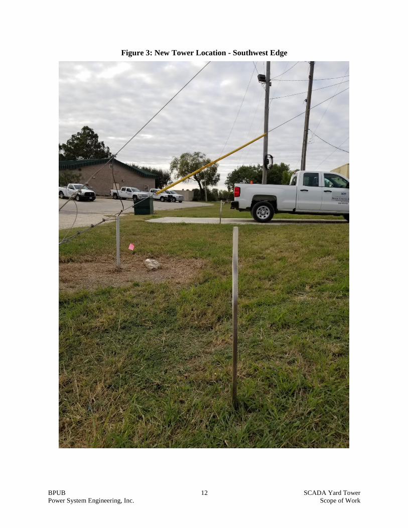
Figure 3: New Tower Location - Southwest Edge

BPUB 13 SCADA Yard Tower
Power System Engineering, Inc. Scope of Work
Figure 4: Cable Entry for Existing Site
BPUB 14 SCADA Yard Tower
Power System Engineering, Inc. Scope of Work
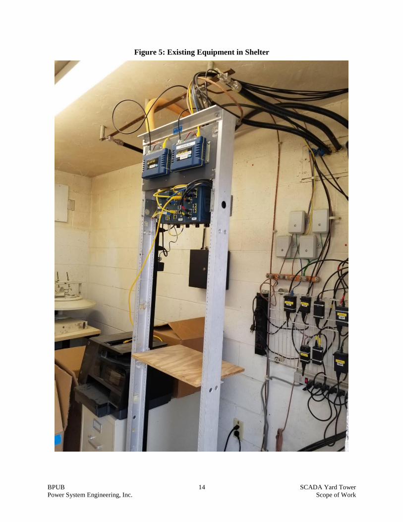
Figure 5: Existing Equipment in Shelter
BPUB 15 SCADA Yard Tower
Power System Engineering, Inc. Scope of Work
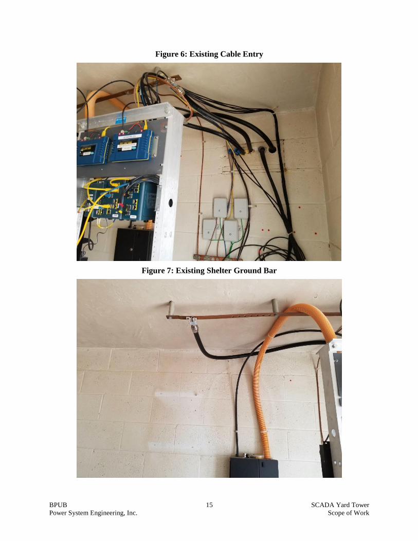
Figure 6: Existing Cable Entry
Figure 7: Existing Shelter Ground Bar
BPUB 16 SCADA Yard Tower
Power System Engineering, Inc. Scope of Work
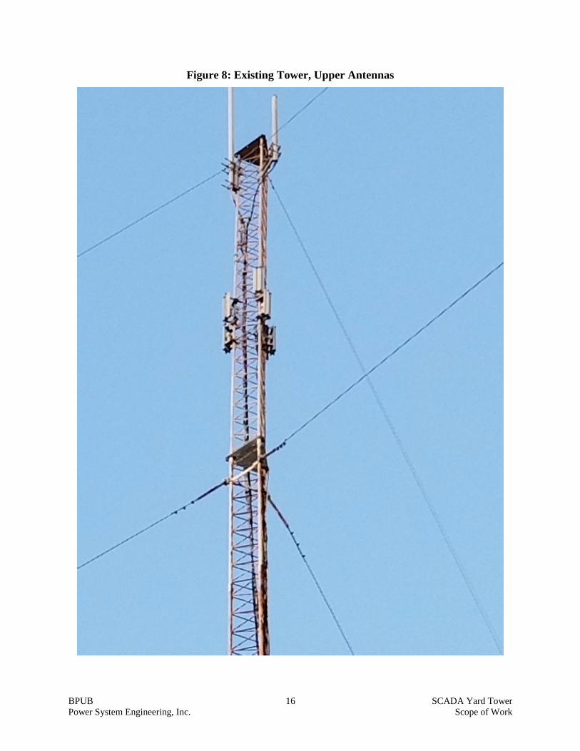
Figure 8: Existing Tower, Upper Antennas

BPUB 17 SCADA Yard Tower
Power System Engineering, Inc. Scope of Work
Figure 9: Existing Tower, Mid Height Antenna