ATTACHMENT 4B - Connecticut€¦ · ATTACHMENT 4B. C&F: 1892202.1 ... Best Management Practices to...
29
ATTACHMENT 4B
Transcript of ATTACHMENT 4B - Connecticut€¦ · ATTACHMENT 4B. C&F: 1892202.1 ... Best Management Practices to...

ATTACHMENT 4B

C&F: 1892202.1
Branford Site
Environmental Assessment Statement
I. PHYSICAL IMPACT
A. WATER FLOW AND QUALITY
No water flow and/or water quality changes are anticipated as a result of the construction
or operation of the proposed facility at the Branford Site. No wetlands were delineated
within 100' of the proposed facility compound at the Branford Site and the paved access
drive will be utilized for access. Best Management Practices to control storm water and
soil erosion during construction will be implemented. The equipment associated with the
facility will discharge no pollutants to area surface or groundwater systems.
B. AIR QUALITY
Under ordinary operating conditions, the equipment that would be used at the proposed
facility would emit no air pollutants of any kind.
C. LAND
Some clearing and minor grading will be necessary in the compound area. The remaining
land of the lessor would remain unchanged by the construction and operation of the
facility.
D. NOISE
The equipment to be in operation at the facility would not emit noise other than that
provided by the operation of the installed heating, air-conditioning and ventilation
system. Some construction related noise would be anticipated during facility
construction, which is expected to take approximately four to six weeks. Temporary
power outages could involve sound from an emergency generator.
E. POWER DENSITY
The cumulative worst-case calculation of power density from AT&T’s operations at the
facility would be 1.19% of the MPE standard. Attached is a copy of the Calculated Radio
Frequency Report prepared by C2 Systems dated April 2, 2012.
F. VISIBILITY
The potential visual impact of the proposed facility was determined by preparation of the
attached Visual Analysis Report prepared by VHB. The potential visibility of the
proposed monopole was assessed within an approximate two-mile radius using a
computer-based, predictive view shed model. As shown in the preliminary report and
C&F: 1892202.1
viewshed map, the proposed tower is expected to be visible above the tree canopy within
an approximately 2,025 acre area of the 8,042-acre study area (a two-mile radius of the
proposed facility) with visibility over open water accounting for 2,000 of the 2,025 acres.
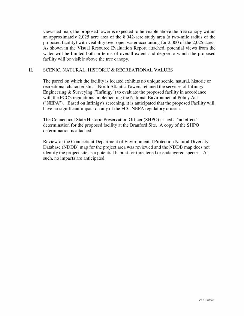
As shown in the Visual Resource Evaluation Report attached, potential views from the
water will be limited both in terms of overall extent and degree to which the proposed
facility will be visible above the tree canopy.
II. SCENIC, NATURAL, HISTORIC & RECREATIONAL VALUES
The parcel on which the facility is located exhibits no unique scenic, natural, historic or
recreational characteristics. North Atlantic Towers retained the services of Infinigy
Engineering & Surveying ("Infinigy") to evaluate the proposed facility in accordance
with the FCC's regulations implementing the National Environmental Policy Act
("NEPA"). Based on Infinigy's screening, it is anticipated that the proposed Facility will
have no significant impact on any of the FCC NEPA regulatory criteria.
The Connecticut State Historic Preservation Officer (SHPO) issued a "no effect"
determination for the proposed facility at the Branford Site. A copy of the SHPO
determination is attached.
Review of the Connecticut Department of Environmental Protection Natural Diversity
Database (NDDB) map for the project area was reviewed and the NDDB map does not
identify the project site as a potential habitat for threatened or endangered species. As
such, no impacts are anticipated.

GA Office: 2255 Sewell Mill Road, Suite 130, Marietta, GA 30062 ~ Phone: 678-444-4463 - Fax: 678-444-4472 WI Office: 64 N. Main Street, Suite B, Hartford, WI 53027 ~ Phone: 262-670-9530 - Fax: 262-670-9560
May 25, 2010 Mr. Roger Laperna North Atlantic Towers, LLC 1001 3rd Ave West, Suite 420 Bradenton, FL 34205 Subject: Wetland Delineation FTP-Branford 171 Short Beach Road, Branford, CT 06405 Infinigy # 226-053 Dear Mr. Laperna: As requested, Infinigy Engineering and Surveying, PLLC (Infinigy) has conducted a wetland delineation review for the proposed wireless communication facility located at 171 Short Beach Road, Branford CT 060405. The State of Connecticut Inland Wetlands and Watercourse Act defines wetlands as: “Wetlands, means land, including submerged land as defined in this regulation, not regulated pursuant to section 22a-28 through 22a-35, inclusive, of the Connecticut General Statutes, which consists of any of the soil types designated as poorly drained, very poorly drained, alluvial and floodplain by the National Cooperative Soils Survey, as it may be amended from time to time, of the National Resources Conservation Service of the U.S. Department of Agriculture (USDA).” The United States Army Corps of Engineers (ACOE) “Wetland Delineation Manual” (1987) criteria was used to determine the presence or absence of wetlands within the proposed wireless communication facility lease area. Pursuant to this methodology, Infinigy identified the three criteria required for the consideration as a wetland: hydric soils, hydrology and hydric vegetation. Hydric soils are identified as soils with a chroma less than 1 or a chroma of 2 with mottling. Hydrology is the effect water has on surface land characteristics (i.e., standing water, erosion, water marks, etc.). Herbaceous vegetation is recorded within a 10-foot radius while shrub and tree species are recorded within a 30-foot radius. Vegetation is given a United States Fish and Wildlife Service (FWS) “indicator status”. Based on the “indicator status”, a determination of hydric vegetation dominance is determined. Based on the Infinigy wetland survey and the property survey entitled “Branford/CT1009; 171 Short Beach Road, Branford CT”, wetlands were not observed within 100 feet of the proposed wireless communication facility compound. As proposed, the wireless communication project will adhere to all local, state and federal environmental regulations, and adverse impacts to “wetlands” are not anticipated at this time. Additionally, based on review of the Google Earth, United States Fish and Wildlife Service National Wetland Inventory (NWI) mapping data, a palustrine forested wetland is depicted approximately 250 feet northwest of the subject property. It is important to note, NWI wetland boundaries are estimated by aerial photograph interpretation and do not represent the ground-verified wetland boundary.
New York Office 11 Herbert Drive Latham, NY 12110 Phone: (518) 690-0790 Fax: (518) 690-0793
www.Infinigy .com
North Atlantic Towers, LLC
GA Office: 2255 Sewell Mill Road, Suite 130, Marietta, GA 30062 ~ Phone: 678-444-4463 - Fax: 678-444-4472 WI Office: 64 N. Main Street, Suite B, Hartford, WI 53027 ~ Phone: 262-670-9530 - Fax: 262-670-9560
Please feel free to contact me with any question or concerns at (518)-690-0970. Respectfully Submitted,
Infinigy Engineering and Surveying, PLLC Mark Kiburz, CPESC Wetland Ecologist

GA Office: 2255 Sewell Mill Road, Suite 130, Marietta, GA 30062 ~ Phone: 678-444-4463 - Fax: 678-444-4472
April 16, 2012
Mr. Dan Shriver North Atlantic Towers, LLC 1001 3rd Avenue West, Suite 420 Bradenton, FL 34205 RE: Branford (CT1109C)
171 Short Beach Road, Branford, CT Coastal Consistency Analysis – Site Plan Review
Dear Mr. Shriver:
Infinigy Engineering PLLC (Infinigy) has conducted a review of the Connecticut Coastal Management Act (CCMA) as outlined in the Connecticut General Statutes (CGS) sections 22a-90 through 22a-112. The CCMA requires “coastal site plan reviews” for the application listed below if the proposed activity or use is located landward of the mean high water mark:
• Site plans submitted to a zoning commission in accordance with CGS section 22a-109; • Plans submitted to a planning commission for subdivision or resubdivision; • Application for special exceptions or special permits submitted to a planning commission, zoning
commission or zoning board of appeals; • Application for variances submitted to a local zoning board of appeals; and • Referrals of proposed municipal projects to a planning commission pursuant to CGS section 8-24
[CGS section 22a-105(b)] As stated within the CCMA, the authority for coastal site plan review lies with the municipal board or commission responsible for the decision on the underlying application. Although the Connecticut Department of Energy and Environmental Protection (CT DEEP) exercises an oversight role in municipal coastal management activities (CGS section 22a-110), the proposed project application does not include a shoreline flood and erosion control structure or a change in the zoning map or regulations. As such, referral to the CT DEEP is not required and the Coastal Site Plan Review process is completed by the governing municipality, in this case, the Connecticut Siting Council. Project Information
The Subject Property for the proposed telecommunications facility, located at 171 Short Beach Road, Branford, Connecticut, is situated within a parking lot on a ±0.87-acre parent parcel of land located along the west side of Short Beach road, identified as C10/000/0027/00009 on the Town of Branford Tax Maps. The parent parcel is developed with an approximately 6,500-square foot commercial building and adjacent paved driveway and parking lot. The property is utilized by AIR, Inc. as a heating and air conditioning business. The current zoning classification of the parent parcel is “R-4”. Specifically, the Subject Property consists of an approximately 2,500-square foot lease area on the northwestern (rear) portion of the parent parcel. It should be noted that this portion of the parent parcel is situated outside the Coastal Boundary, although the southeastern (front) portion of the parent parcel lies within the Coastal Boundary.
New York Office 11 Herbert Drive Latham, NY 12110 Phone: (518) 690-0790 Fax: (518) 690-0793
www.infinigy.com

Mr. Dan Shriver April 16, 2012 North Atlantic Towers, LLC Page #2
GA Office: 2255 Sewell Mill Road, Suite 130, Marietta, GA 30062 ~ Phone: 678-444-4463 - Fax: 678-444-4472
North Atlantic Towers, LLC (NAT) proposes to install a 120-foot tall, monopole-style telecommunications tower and associated ground-level equipment within a 50’ x 50’ fenced equipment compound on the northwestern portion of the parent parcel. Access to the telecommunications facility will be from Short Beach Road via the existing paved driveway and parking area.
The parent parcel is located within the coastal boundary zone as defined in CGS Section 22a-94(b). As stated within the CCMA, and verified by Connecticut Department of Energy and Environmental Protection (DEEP), Coastal Site Plan Review section, coastal site plan review is required for projects located within the coastal boundary. Therefore, a coastal site plan review shall be completed by the Connecticut Siting Council during the project review and approval process.
Coastal Consistency Review Summary of Findings
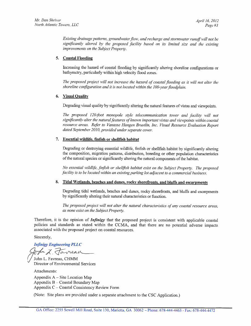
As proposed, the NAT project will not result in adverse impacts to coastal resources as defined within the CCMA. The CCMA identifies eight (8) potential adverse impacts to coastal resources. Potential adverse impacts on each resource area, as identified within the CCMA are defined below as they are applicable to each project.
1. Water Quality
Degrading water quality of coastal waters by introducing significant amounts of suspended solids, nutrients, toxics, heavy metals or pathogens, or through the significant alteration of temperature, pH, dissolved oxygen or salinity.
The proposed project will not affect water quality within nearby Talmage Pond or associated wetlands which are located greater than 500 feet to the west of the project site, or local water bodies connected with coastal waters. Since the proposed wireless telecommunications compound creates minimal impervious surface and is underlain by a gravel surface, no significant stormwater runoff will be generated by the proposed project.
2. Coastal Waters Circulation Patterns
Degrading existing circulation patterns of coastal waters by impacting tidal exchange or flushing rates, freshwater input, or existing basin characteristics and channel contours.
The proposed project is located on a parcel that is currently developed and is located outside of tidally-influenced coastal water areas and as such, will not impact current drainage or circulation patterns.
3. Natural Erosion Patterns
Degrading natural erosion patterns by significantly altering littoral transport of sediments in terms of deposition or source reduction.
The proposed project will not affect littoral transport of sediments since the proposed facility location is not on a shoreline.
4. Natural or Existing Drainage Patterns
Degrading natural or existing drainage patterns by significantly altering groundwater flow and recharge and volume runoff.

GA Office: 2255 Sewell Mill Road, Suite 130, Marietta, GA 30062 ~ Phone: 678-444-4463 - Fax: 678-444-4472
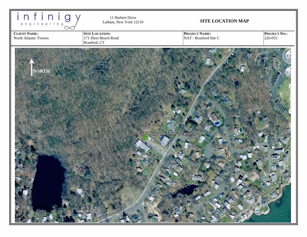
APPENDIX A
SITE LOCATION MAP
11 Herbert Drive
Latham, New York 12110
SITE LOCATION MAP
CLIENT NAME: SITE LOCATION: PROJECT NAME: PROJECT NO.: North Atlantic Towers 171 Short Beach Road
Branford, CT NAT - Branford Site C 226-053
NORTH

GA Office: 2255 Sewell Mill Road, Suite 130, Marietta, GA 30062 ~ Phone: 678-444-4463 - Fax: 678-444-4472
APPENDIX B
COASTAL BOUNDARY MAP

11 Herbert Drive
Latham, New York 12110
Coastal Boundary Map (Map Source: CT Dept. of Energy and Environmental Protection)
CLIENT NAME: SITE LOCATION: PROJECT NAME: PROJECT NO.: North Atlantic Towers 171 Short Beach Road
Branford, CT Branford Site C 226-053
Approximate Site Location

GA Office: 2255 Sewell Mill Road, Suite 130, Marietta, GA 30062 ~ Phone: 678-444-4463 - Fax: 678-444-4472
APPENDIX C
COASTAL CONSISTENCY REVIEW FORM

DEP-APP-004 1 of 5 Rev. 08/08/11
Coastal Consistency Review Form Please complete this form in accordance with the instructions (DEP-INST-004). Print or type unless otherwise noted.
Part I: Project Information
1. Applicant Name: North Atlantic Towers, LLC
Mailing Address: 1001 3rd Avenue West, Suite 420
City/Town: Bradenton State: FL Zip Code: 34205
Business Phone: (941) 757-5010 ext.: Fax:
Contact Person: Dan Shriver Phone: ext.
E-mail:
2. Preparer Name: Infinigy Engineering, LLC
Mailing Address: 11 Herbert Drive
City/Town: Latham State: NY Zip Code: 12110
Business Phone: (518) 690-0790 ext.: 39 Fax: (518) 690-0793
Contact Person: John Favreau Phone: (518) 858-7068 ext.
E-mail: [email protected]
3. Street Address or Description of Location of the Project Site:
171 Short Beach Road, City or Town: Branford CT
4. Brief Project Description:
North Atlantic Towers, LLC proposes to install a 120-foot tall monopole telecommunications tower and 2,500 sq. ft. fenced equipment compound area within an existing parking lot.
5. Is the project located within the coastal boundary as defined in CGS Section 22a-94(b)?
Yes No
If you answered Yes to this question, complete the entire form.
If you answered No to this question, and your project is located in a coastal area, skip Parts II through V and complete Parts VI, VII and VIII.
DEEP USE ONLY
Application No.:
Analyst Assigned:
Date Received (OLISP):

DEP-APP-004 2 of 5 Rev. 08/08/11
Part II: Identification of Applicable Coastal Use and Activity Policies and Standards Identify all statutory goals and policies in or referenced by Section 22a-92 of the Coastal Management Act applicable to the proposed activities by checking the applicable boxes in the following table.
General Development* - CGS Sections 22a-92(a)(1), 22a-92(a)(2), 22a-92(a)(9), 22a-92(a)(9)
Water-Dependent Uses - CGS Sections 22a-92(a)(3), 22a-92(b)(1)(A)
Ports and Harbors - CGS Section 22a-92(b)(1)(C)
Coastal Structures and Filling - CGS Section 22a-92(b)(1)(D)
Dredging and Navigation - CGS Sections 22a-92(c)(1)(C), 22a-92(c)(1)(D)
Boating - CGS Section 22a-92(b)(1)(G)
Fisheries - CGS Section 22a-92(c)(1)(I)
Coastal Recreation And Access - CGS Sections 22a-92(a)(6), 22a-92(C)(1)(j), 22a-92(c)(1)(K)
Sewer and Water Lines - CGS Section 22a-92(b)(1)(B)
Fuel, Chemicals And Hazardous Materials - CGS Sections 22a-92(b)(1)(C), 22a-92(b)(1)(E), 22a-92(c)(1)(A)
Transportation - CGS Sections 22a-92(b)(10)(F), 22a-92(c)(1)(F), 22a-92(c)(1)(G), 22a-92(c)(1)(H)
Solid Waste - CGS Section 22a-92(a)(2)
Dams, Dikes and Reservoirs - CGS Section 22a-92(a)(2)
Cultural Resources - CGS Section 22a-92(b)(1)(J)
Open Space and Agricultural Lands - CGS Section 22a-92(a)(2)
* applicable to all proposed activities Part III: Consistency With Applicable Statutory Coastal Use and Activity Goals and Policies
Explain how the proposed activity is consistent with the applicable coastal activities goals and policies identified in Part II and describe any mitigation necessary to offset adverse impacts.
The proposed project does not pose adverse impacts with respect to the items referenced in Part II.

DEP-APP-004 3 of 5 Rev. 08/08/11
Part IV: Identification of Applicable Coastal Resources and Coastal Resource Policies Identify the coastal resources and associated statutory policies that apply to your project by checking the applicable boxes in the following table.
Coastal Resources
on-site
adjacent to work
site
off-site but potentially
affected by the project
General Resources* - CGS Sections 22a-93(7), 22a-92(a)(2)
X
X
X
Beaches & Dunes - CGS Sections 22a-93(7)(C), 22a-92-(b)(2)(C), 22a-92(c)(1)(K)
Bluffs & Escarpments - CGS Sections 22a-93(7)(A), 22a-92(b)(2)(A) Coastal Hazard Area - CGS Sections 22a-93(7)(H), 22a-92(a)(2), 22a-92(b)(2)(F), 22a-92(b)(2)(J), 22a-92(c)(2)(B), 22a-92(a)(5)
Coastal Waters & Estuarine Embayments - CGS Sections 22a-93(5), 22a-93(7)(K), 22a-93(7)(L), 22a-93(7)(G), 22a-92(a)(2), 22a-92(c)(2)(A)
Developed Shorefront - CGS Sections 22a-93(7)(I), 22a-92(b)(2)(G) Freshwater Wetlands and Watercourses - CGS Sections 22a-93(7)(F), 22a-92(a)(2)
Intertidal Flats - CGS Sections 22a-93(7)(D), 22a-92(b)(2)(D), 22a-92(c)(1)(K)
Islands - CGS Sections 22a-93(7)(J), 22a-92(b)(2)(H) Rocky Shorefront - CGS Sections 22a-93(7)(B), 22a-92(b)(2)(B) Shellfish Concentration Areas - CGS Sections 22a-93(7)(N), 22a-92(c)(1)(I)
Shorelands - CGS Sections 22a-93(7)(M), 22a-92(b)(2)(I) Tidal Wetlands - CGS Sections 22a-93(7)(E), 22a-92(a)(2), 22a-92(b)(2)(E), 22a-92(c)(1)(B)
* applicable to all proposed activities
Part V: Consistency with Applicable Statutory Coastal Resource Goals and Policies
Explain how the proposed activity is consistent with the applicable statutory coastal resource goals and policies identified in Part IV and describe any mitigation necessary to offset adverse impacts.
The proposed wireless communication facility falls within the Coastal Boundary Mapping. The proposed project area is currently a paved parking lot; therefore no impacts to coastal resources are anticpated.

DEP-APP-004 4 of 5 Rev. 08/08/11
Part VI: Identification of Potential Adverse Impacts Identify the adverse impact categories that apply to the proposed activity. Check the applicable box if the proposed activity has the potential to generate any adverse impacts defined in the Coastal Management Act and referred to in the following table. If the category is applicable to the proposed activity, you may describe in Part VII project design features which may eliminate or minimize the potential for identified adverse impacts.
Potential Resource Impacts
Applicable
Not Applicable
Characteristics & Functions of Resources - CGS Section 22a-93(15)(H) Coastal Flooding - CGS Section 22a-93(15)(E) Coastal Waters Circulation Patterns - CGS Section 22a-93(15)(B) Drainage Patterns - CGS Section 22a-93(15)(D) Patterns of Shoreline Erosion and Accretion - CGS Section 22a-93(15)(C) Visual Quality - CGS Section 22a-93(15)(F) Water Quality - CGS Section 22a-93(15)(A) Wildlife, Finfish, Shellfish Habitat - CGS Section 22a-93(15)(G)
Potential Impacts on Water Dependent Uses
Applicable
Not Applicable
Locating a non-water-dependent use on a site suited to or planned for a water-dependent use - CGS Section 22a-93(17)
Replacing an existing water-dependent use with a non-water-dependent use - CGS Section 22a-93(17)
Siting a non-water-dependent use which reduces or eliminates public access to marine or tidal waters - CGS Section 22a-93(17)
DEP-APP-004 5 of 5 Rev. 08/08/11
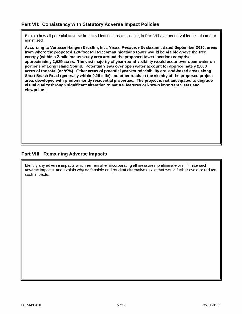
Part VII: Consistency with Statutory Adverse Impact Policies
Explain how all potential adverse impacts identified, as applicable, in Part VI have been avoided, eliminated or minimized.
According to Vanasse Hangen Brustlin, Inc., Visual Resource Evaluation, dated September 2010, areas from where the proposed 120-foot tall telecommunications tower would be visible above the tree canopy (within a 2-mile radius study area around the proposed tower location) comprise approximately 2,025 acres. The vast majority of year-round visibility would occur over open water on portions of Long Island Sound. Potential views over open water account for approximately 2,000 acres of the total (or 99%). Other areas of potential year-round visibility are land-based areas along Short Beach Road (generally within 0.25 mile) and other roads in the vicinity of the proposed project area, developed with predominantly residential properties. The project is not anticipated to degrade visual quality through significant alteration of natural features or known important vistas and viewpoints.
Part VIII: Remaining Adverse Impacts
Identify any adverse impacts which remain after incorporating all measures to eliminate or minimize such adverse impacts, and explain why no feasible and prudent alternatives exist that would further avoid or reduce such impacts.

11 Herbert Drive
Latham, New York 12110
MAP OF IMPORTANT BIRD AREAS Map Source: National Audubon Society – Important Bird Ares in the US
(http://www.audubon.org/bird/iba)
CLIENT NAME: SITE LOCATION: PROJECT NAME: PROJECT NO.: North Atlantic Towers 171 Short Beach Road, Branford, Connecticut NAT – Branford/Site C 226-053
Proposed Tower Location
NORTH Topsmead State Forest
(Approximately 6 miles from tower site) White Memorial Foundation Nature Preserve
(Approximately 5.5 miles from tower site)
Approximate Proposed Tower Location
(171 Short Beach Road)
Quinnipiac River Tidal Marsh (Approximately 5.5 to 7 miles from proposed tower site)
East Rock Park (Approximately 6 miles from proposed tower site)
Sandy Point The IBA is actually the barrier beach (sand spit) system protruding into New Haven Harbor from the west side, seen to the northwest of the map icon. (Approximately 4.7 miles from the proposed tower site)
Lighthouse Point Park (Approximately 2.6 miles from proposed tower site)

C Squared Systems, LLC 65 Dartmouth Drive, A3
Auburn, NH 03032 Phone: (603) 644 2800
Calculated Radio Frequency Emissions
Air, Inc.
171 Short Beach Road, Branford, CT 06405
April 2, 2012

i
Table of Contents
1. Introduction .............................................................................................................................................................. 1
2. FCC Guidelines for Evaluating RF Radiation Exposure Limits .............................................................................. 1
3. RF Exposure Prediction Methods ............................................................................................................................ 2
4. Calculation Results .................................................................................................................................................. 3
5. Conclusion ............................................................................................................................................................... 4
6. Statement of Certification ........................................................................................................................................ 4
Attachment A: References ............................................................................................................................................ 5
Attachment B: FCC Limits for Maximum Permissible Exposure (MPE) .................................................................... 6
Attachment C: AT&T’s Antenna Model Data Sheets and Electrical Patterns ............................................................. 8
List of Tables
Table 1: Carrier % MPE Information at Base of Proposed Tower ............................................................................... 3
Table 2: FCC Limits for Maximum Permissible Exposure (MPE) .............................................................................. 6
List of Figures
Figure 1: Graph of FCC Limits for Maximum Permissible Exposure (MPE) .............................................................. 7

171 Short Beach Road, Branford, CT 1 April 2, 2012
1. Introduction
The purpose of this report is to investigate compliance with applicable FCC regulations for the proposed North Atlantic Towers facility located at the Air, Inc. Building, 171 Short Beach Road,Branford, CT. AT&T is proposing to locate a wireless communications facility at the proposed site. The coordinates of the site are 41-15-46.04 N, 72-50-3.94W.
AT&T is proposing the following:
1) Install 12 quad-band panel antennas (4 per sector) at 120’ AGL; 2) Install an equipment shelter on the ground to house the base-station equipment;
2. FCC Guidelines for Evaluating RF Radiation Exposure Limits
In 1985, the FCC established rules to regulate radio frequency (RF) exposure from FCC licensed antenna facilities. In 1996, the FCC updated these rules, which were further amended in August 1997 by OET Bulletin 65 Edition 97-01. These new rules include Maximum Permissible Exposure (MPE) limits for transmitters operating between 300 kHz and 100 GHz. The FCC MPE limits are based upon those recommended by the National Council on Radiation Protection and Measurements (NCRP), developed by the Institute of Electrical and Electronics Engineers, Inc., (IEEE) and adopted by the American National Standards Institute (ANSI).
The FCC general population/uncontrolled limits set the maximum exposure to which most people may be subjected. General population/uncontrolled exposures apply in situations in which the general public may be exposed, or in which persons that are exposed as a consequence of their employment may not be fully aware of the potential for exposure or cannot exercise control over their exposure.
Public exposure to radio frequencies is regulated and enforced in units of milliwatts per square centimeter (mW/cm2). The general population exposure limits for the various frequency ranges are defined in the attached “FCC Limits for Maximum Permissible Exposure (MPE)” in Attachment B of this report.
Higher exposure limits are permitted under the occupational/controlled exposure category, but only for persons who are exposed as a consequence of their employment and who have been made fully aware of the potential for exposure, and they must be able to exercise control over their exposure. General population/uncontrolled limits are five times more stringent than the levels that are acceptable for occupational, or radio frequency trained individuals. Attachment B contains excerpts from OET Bulletin 65 and defines the Maximum Exposure Limit.
Finally, it should be noted that the MPE limits adopted by the FCC for both general population/uncontrolled exposure and for occupational/controlled exposure incorporate a substantial margin of safety and have been established to be well below levels generally accepted as having the potential to cause adverse health effects.

171 Short Beach Road, Branford, CT 2 April 2, 2012
3. RF Exposure Prediction Methods
The emission field calculation results displayed in the following figures were generated using the following formula as outlined in FCC bulletin OET 65:
××
= 2
2
46.1 Density Power
REIRP
πx Off Beam Loss
Where:
EIRP = Effective Isotropic Radiated Power
R = Radial Distance = ( )22 VH +
H = Horizontal Distance from antenna in meters
V = Vertical Distance from radiation center of antenna in meters
Ground reflection factor of 1.6
Off Beam Loss determined by the selected antenna pattern
These calculations assume that the antennas are operating at 100 percent capacity and power, and that all antenna channels are transmitting simultaneously. Obstructions (trees, buildings, etc.) that would normally attenuate the signal are not taken into account. As a result, the predicted signal levels reported below are much higher than the actual signal levels will be from the finished installations.

171 Short Beach Road, Branford, CT 3 April 2, 2012
4. Calculation Results
Table 1 below outlines the power density information for the proposed tower. Because the antennas used by AT&T are directional in nature, the majority of the RF power is focused towards the horizon. As a result, there will be less RF power directed below the antennas relative to the horizon, and consequently lower power density levels around the base of the proposed monopole. Please refer to Attachment C for the vertical patterns of the proposed AT&T antennas. The % MPE values in Table 1 are calculated at 6’ above ground (to approximate the height of a human standing at base of the tower) and include a nominal 10 dB off-beam pattern loss to account for the lower relative gain below the directional antennas.
Table 1: Carrier % MPE Information at Base of Proposed Tower1
1 Calculated values include a -10 dB off-beam loss factor (see Attachment C) due to relevant antenna patterns.
Carrier Antenna ModelAntenna Height (Feet)
Operating Frequency
(MHz)
Number of
Trans.
ERP Per Transmitter
(Watts)
Power Density
(mw/cm2)Limit %MPE
AT&T UMTS P65-15-XLH-RR 120 1900 1 500 0.0014 1.0000 0.14%AT&T LTE P65-15-XLH-RR 120 734 1 500 0.0014 0.4893 0.28%
AT&T UMTS P65-15-XLH-RR 120 880 1 500 0.0014 0.5867 0.24%AT&T GSM P65-15-XLH-RR 120 1900 1 427 0.0012 1.0000 0.12%AT&T GSM P65-15-XLH-RR 120 880 3 296 0.0025 0.5867 0.42%
Total 1.19%

171 Short Beach Road, Branford, CT 4 April 2, 2012
5. Conclusion
The above analysis verifies that emissions from the proposed installation will be below the maximum power density levels as outlined by the FCC in the OET Bulletin 65 Ed. 97-01. Even when using conservative methods, the cumulative power density from the transmit antennas at the facility is below the limits for the general public. The highest expected percent of Maximum Permissible Exposure at the base of the proposed tower is 1.19% of the FCC limit.
As noted in Section 3, conservative assumptions are taken into account when calculating the predicted power density. As a result, the predicted %MPE levels are more conservative (higher) than the actual %MPE levels will be from the proposed installation.
6. Statement of Certification
I certify to the best of my knowledge that the statements in this report are true and accurate. The calculations follow guidelines set forth in ANSI/IEEE Std. C95.3, ANSI/IEEE Std. C95.1 and FCC OET Bulletin 65 Edition 97-01.
April 2, 2012
Daniel L. Goulet C Squared Systems, LLC
Date

171 Short Beach Road, Branford, CT 5 April 2, 2012
Attachment A: References
OET Bulletin 65 - Edition 97-01 - August 1997 Federal Communications Commission Office of Engineering & Technology
ANSI C95.1-1982, American National Standard Safety Levels With Respect to Human Exposure to Radio Frequency Electromagnetic Fields, 300 kHz to 100 GHz IEEE-SA Standards Board
IEEE Std C95.3-1991 (Reaff 1997), IEEE Recommended Practice for the Measurement of Potentially Hazardous Electromagnetic Fields - RF and Microwave IEEE-SA Standards Board

171 Short Beach Road, Branford, CT 6 April 2, 2012
Attachment B: FCC Limits for Maximum Permissible Exposure (MPE)
(A) Limits for Occupational/Controlled Exposure2
Frequency Range (MHz)
Electric Field Strength (E)
(V/m)
Magnetic Field Strength (E)
(A/m)
Power Density (S) (mW/cm2)
Averaging Time |E|2, |H|2 or S (minutes)
0.3-3.0 614 1.63 (100)* 6 3.0-30 1842/f 4.89/f (900/f2)* 6 30-300 61.4 0.163 1.0 6
300-1500 - - f/300 6 1500-100,000 - - 5 6
(B) Limits for General Population/Uncontrolled Exposure3
Frequency Range (MHz)
Electric Field Strength (E)
(V/m)
Magnetic Field Strength (E)
(A/m)
Power Density (S) (mW/cm2)
Averaging Time |E|2, |H|2 or S (minutes)
0.3-1.34 614 1.63 (100)* 30 1.34-30 824/f 2.19/f (180/f2)* 30 30-300 27.5 0.073 0.2 30
300-1500 - - f/1500 30 1500-100,000 - - 1.0 30
f = frequency in MHz * Plane-wave equivalent power density
Table 2: FCC Limits for Maximum Permissible Exposure (MPE)
2 Occupational/controlled limits apply in situations in which persons are exposed as a consequence of their employment provided those persons are fully aware of the potential for exposure and can exercise control over their exposure. Limits for occupational/controlled exposure also apply in situations when an individual is transient through a location where occupational/controlled limits apply provided he or she is made aware of the potential for exposure 3 General population/uncontrolled exposures apply in situations in which the general public may be exposed, or in which persons that are exposed as a consequence of their employment may not be fully aware of the potential for exposure or cannot exercise control over their exposure

171 Short Beach Road, Branford, CT 7 April 2, 2012
Plane-wave Equivalent Power Density
Frequency (MHz)
Figure 1: Graph of FCC Limits for Maximum Permissible Exposure (MPE)
1.34 100,000 1,500

171 Short Beach Road, Branford, CT 8 April 2, 2012
Attachment C: AT&T’s Antenna Model Data Sheets and Electrical Patterns
716 MHz
Manufacturer: Powerwave Model #: P65-15-XLH-RR
Frequency Band: 698-806 Gain: 11.9 dBd
Vertical Beamwidth: 17 deg
Horizontal Beamwidth: 73 deg
Polarization: ±45 deg Size L x W x D: 51” x 12” x 6”
880 MHz
Manufacturer: Powerwave Model #: P65-15-XLH-RR
Frequency Band: 806-894 Gain: 12.6 dBd
Vertical Beamwidth: 17 deg
Horizontal Beamwidth: 63 deg
Polarization: ±45 deg Size L x W x D: 51” x 12” x 6”
1950 MHz
Manufacturer: Powerwave Model #: P65-15-XLH-RR
Frequency Band: 1710-2170 Gain: 14.6 dBd
Vertical Beamwidth: 7.5 deg
Horizontal Beamwidth: 61 deg
Polarization: ±45 deg Size L x W x D: 51” x 12” x 6”