ATP Piper Archer Training Supplement - Amazon S3..... ..... 3 Pitot Static..... 3 Fuel System..... 3...
56
• a Piper Archer Training Supplement 904-595-7940 ATPFlightSchool.com Revised 2018-01-05
Transcript of ATP Piper Archer Training Supplement - Amazon S3..... ..... 3 Pitot Static..... 3 Fuel System..... 3...

• a
Piper ArcherTraining Supplement
904-595-7940 ATPFlightSchool.com
Revised 2018-01-05

Copyright © 2018 Airline Transport Professionals.The content of this manual is furnished for informational use only, and is subject to change without notice. Airline Transport Professionals assumes no responsibility or liability for any errors or inaccuracies that may appear in this manual. This manual does not replace the Piper Archer Pilot Operating Handbook, FAA Airplane Flying Handbook, or Practical Test Standards / Airman Certification Standards. Nothing in this manual shall be interpreted as a substitute for the exercise of sound judgement.No part of this publication may be reproduced, stored in a retrieval system, or transmitted, in any form or by any means electronic, mechanical or otherwise, without the prior written permission of Airline Transport Professionals.
IMPORTANT NOTICE
Refer to POH/AFM
Do not use procedures listed without referencing the full procedures described in the approved Owner’s Manual, POH, or POH/AFM specific to the airplane you are flying. Endurance and fuel capacities may vary considerably depending on the specific model / serial number being flown and any modifications it may have.
To view recent changes to this supplement, visit: atpflightschool.com/changes/supp-archer

Contents
Revised 2018-01-05
Aircraft Systems ...................................1Engine ..........................................................1Oil .................................................................2Propeller ......................................................2Landing Gear ................................................2Brakes ..........................................................2Flaps .............................................................3Pitot Static ....................................................3Fuel System ..................................................3Electrical System ..........................................4Garmin G500 ................................................5Standby Instruments ....................................8G500 Failures & Partial-Panel .....................9Heater ........................................................12Stall Warning Horn .....................................12Inoperative Instruments & Equipment .......12
Performance / Weight & Balance ....13Piper Archer V-Speeds ...............................13Performance Charts ...................................13Sample Weight & Balance Problem ............14Formulas ....................................................15CG Envelope Graph .....................................15
Departure Procedures ......................16Passenger Briefing ....................................16Pre-Takeoff Briefing ...................................16Normal Takeoff (Flaps 0°) .........................17Short-Field Takeoff & Climb (Flaps 25°) ....17Soft-Field Takeoff & Climb (Flaps 25°) ......18
Arrival Procedures .............................19Piper Archer Landing Criteria ....................19Good Planning = Good Landing ................19Approach Briefing – Verbalize the Plan ....19Approach Briefing ..................................... 20Announced Calls on Approach .................. 20Stabilized Approach ...................................21Aiming Point ..............................................21Pitch & Power ........................................... 22
Go Around Philosophy ...............................23Managing Energy ......................................23Gust Factor ................................................23Seat Position .............................................23Flap Setting ................................................24Traffic Pattern Operations .........................24Short-Field Approach & Landing ...............27Soft-Field Approach & Landing ................. 28Crosswind Approach & Landing ................ 29Go-Around Procedure ................................31Rejected or Balked Landing.......................31Precision Approach & Landing ..................32Non-Precision Approach & Landing ..........32Circling Approach ...................................... 34Holding ...................................................... 34
In-Flight Maneuvers ......................... 35Clean Configuration Flow ............................35Landing Configuration Flow .......................35Steep Turns ............................................... 36Maneuvering During Slow Flight ............... 36Power-Off Stall ...........................................37Power-On Stall ............................................37Emergency Descent .................................. 38Chandelles ................................................. 38Lazy Eights .................................................39Eights On Pylons ....................................... 40Steep Spirals ..............................................41Accelerated Stall.........................................41Secondary Stall (Power-On) ...................... 42Secondary Stall (Power-Off) ..................... 42Elevator Trim Stall ......................................43Cross-Control Stall..................................... 44
Oral Review ........................................ 45Lost Comm Procedure (FAR 91.185) ..........45FAR Review .................................................45Sample Oral Questions ............................. 46
172 & Archer Differences ................. 49


Aircraft Systems • 1
SECTION 1
Aircraft Systems
EngineThe Archer is equipped with a Lycoming, 4-cylinder, O-360 (opposed, 360 cubic inch) engine rated at 180 horsepower at 2700 RPM. The engine is direct drive (crankshaft connected directly to the propeller), horizontally opposed (pistons oppose each other), piston driven, carbureted and normally aspirated (no turbo or supercharging). Engine ignition is provided through the use of two engine-driven magnetos, which are independent of the aircraft's electrical system and each other.
L Lycoming
H Horizontally Opposed
A Air Cooled
N Normally Aspirated
D Direct Drive
Carburetor IcingUnder certain atmospheric conditions at temperatures of 20° to 70° F (-5° to 20° C), it is possible for ice to form in the induction system, even in summer weather. This is due to the high air velocity through the carburetor venturi and the absorption of heat from this air by vaporization of the fuel. To avoid this, carburetor heat is provided to replace the heat lost by vaporization. The initial signs of carburetor ice can include engine roughness and a drop in RPM. Carburetor heat should be selected on full if carburetor ice is encountered. Adjust mixture for maximum smoothness.
Note: Partial carburetor heat may be worse than no heat at all, since it may melt part of the ice, which will refreeze in the intake system. Therefore when using carburetor heat, always use full heat and when the ice is removed, return the control to the full cold position.

2 • Aircraft Systems
From the Archer POH, in regards to carburetor heat usage during approach:
"Carburetor heat should not be applied unless there is an indication of carburetor icing, since the use of carburetor heat causes a reduction in power which may be critical in case of a go-around. Full throttle operation with carburetor heat on can cause detonation."
OilAcceptable range for oil in the Archer is 6–8 quarts. Never depart with the oil indicating below 6 quarts.
ATP policy states any time a full quart of oil can be added to the Archer oil system, a full quart should be added. Never add less than a full quart.
PropellerThe Archer is equipped with a Sensenich two-bladed, fixed pitch, metal propeller. Propeller diameter is 76 inches. Maximum RPM (red line) is 2700 RPM.
Landing GearThe landing gear is a fixed, tricycle type gear, with oleo (air/oil) struts providing shock absorption for all three wheels. The nose wheel contains a shimmy dampener, which damps nose wheel vibrations during ground operations and centers the nose wheel in the air. The nose wheel is linked to the rudder pedals by a steering mechanism which turns the nosewheel up to 20° each side of center.
BrakesThe Archer is equipped with hydraulically actuated disc brakes on the main landing gear wheels. Braking is accomplished by depressing the tops of the rudder pedals. Both toe brakes and the parking brake have separate braking cylinders, but share a hydraulic reservoir. The brake fluid reservoir is installed on the top left front face of the firewall. To set the parking brake, pull back on the brake lever, depressing the knob attached to the left side of the handle, then release the brake lever. To disengage the parking brake, pull back on the brake lever to disengage the catch mechanism, then allow the handle to swing forward.
The parking brake is not to be used in training or flight checks with ATP.

Aircraft Systems • 3
FlapsThe Archer is equipped with a manual flap system. The flaps are extended with a lever located between the two pilot seats. Flap settings are 0°, 10°, 25°, and 40°, and are spring-loaded to return to the 0 ° position.
ATP operations require flaps 25° for all landings except:• Short and soft field, flaps 40°• Precision approach, flaps 10°
Pitot StaticPitot and static pressure are both received from a pitot head installed on the bottom of the left wing. An alternate static source is located inside the cabin under the left side of the instrument panel, for use in the event of static port blockage. When using the alternate static source, the storm window and cabin vents must be closed and the cabin heater and defroster must be on. This will reduce the pressure differential between the cockpit and the atmosphere, reducing pitot-static error. The pitot-static instruments are the airspeed indicator, altimeter, and vertical speed indicator.
Both the pitot and static lines can be drained through separate drain valves located on the left lower side of the fuselage interior.
Fuel SystemThe Archer, which uses 100 low lead avgas (blue), is equipped with two 25 gallon fuel tanks. One gallon is unusable in each tank. There is one engine-driven and one electrically-driven fuel pump. The electric fuel pump is used for all takeoffs and landings, and when switching tanks.
ATP uses the electric fuel pump for in-flight maneuvers, except for steep turns.
The aircraft is equipped with a three-position fuel selector control. The positions are “L”, “R”, and “OFF”.
The correct procedure for switching tanks in cruise flight is:
1. Electric fuel pump on2. Fuel selector from “L” to “R” or from “R” to “L”3. Check fuel pressure4. Electric fuel pump off5. Check fuel pressure

4 • Aircraft Systems
An electric engine priming system is provided to facilitate starting. The primer switch is located on the far left side of the overhead switch panel.
CAUTION: DO NOT OVER-PRIME. Over-priming washes lubrication from cylinder walls and increases fire risk. Always follow the checklist for primer usage.
Fuel ManagementThroughout operation, checklists will call for "Fuel Selector... Proper Tank." It is important to monitor fuel burn to maintain a balanced fuel load. The Archer POH does not provide a limitation on fuel imbalance. It is ATP's policy that the fuel selector should not be changed during critical phases of flight, to include takeoff and operations below pattern altitude, unless called for on an emergency checklist.
During cruise flight and maneuvers, fuel load should be monitored and the fuel selector should be selected to the fullest tank only when a noticeable difference in fuel load occurs. 30 minutes of operation should result in a fuel load difference of several gallons, and is a good guideline for fuel selector changes.
During pattern work operations, the fuel selector should only be changed while on the ground during a Full Stop/Taxi Back procedure. It is critical to follow the proper procedure for changing fuel tanks while on the ground, as well as while in flight. Failure to follow the proper fuel selector change procedure can lead to interruption in fuel flow, and engine failure, during a critical phase of flight.
Electrical SystemThe Archer is equipped with a 28-volt DC electrical system and a 24-volt lead-acid battery. Electrical power is supplied by a 70-amp, engine-driven alternator. A voltage regulator maintains a constant 28-volt output from the alternator. An overvoltage relay is located on the forward left side of the fuselage behind the instrument panel. Alternator output is displayed on a digital ammeter on the instrument panel.
Alternator FailureIn the case of the "ALTERNATOR INOP" annunciator, follow the "ALT Annunciator Illuminated" checklist. The expanded procedure can be found in the Archer POH Section 3.25:
"Loss of alternator output is detected through zero reading on the ammeter. Before executing the following procedure, ensure that the reading is zero and not merely low by actuating an electrically powered device, such as the landing light. If no increase in the ammeter reading is noted, alternator failure can be assumed. The

Aircraft Systems • 5
electrical load should be reduced as much as possible. Check the alternator circuit breakers for a popped circuit.
The next step is to attempt to reset the overvoltage relay. This is accomplished by moving the ALT switch to OFF for one second and then to ON. If the trouble was caused by a momentary overvoltage condition (30.5 volts and up) this procedure should return the ammeter to a normal reading.
Note: Low Bus Voltage Annunciator will be illuminated.
If the ammeter continues to indicate "0" output, or if the alternator will not remain reset, turn off the ALT switch, maintain minimum electrical load, and land as soon as practical. Anticipate complete electrical failure. Duration of battery power will be dependent on electrical load and battery condition prior to failure."
The battery is used as a source of emergency electrical power and for engine starts. High drain items include the lights, vent fan, heater, radios, and PFD/MFD. If an electrical problem arises, always check circuit breakers. If a circuit breaker is popped, reset only one time.
CAUTION: Do not reset popped circuit breakers if smoke can be smelled.
Other electrical components include the standby attitude indicator, the starter, the electric fuel pump, electric engine primer, the stall warning horn, the ammeter, and the annunciator panel.
Garmin G500The Archer is equipped with the Garmin G500 electronic flight deck. The G500 powers on with the battery master switch.
PRIMARY FLIGHT DISPLAY (PFD)
MULTI-FUNCTION DISPLAY (MFD)

6 • Aircraft Systems
G500 Components The G500 is comprised of six main components:
• Primary Flight Display (PFD, left) and Multi-Function Display (MFD, right)
• Attitude Heading Reference System (AHRS)• Air Data Computer (ADC)• Magnetometer• Temperature Probe• Dual Garmin GNS 430 GPS
The PFD (left) shows primary flight information in place of traditional pitot-static and gyroscopic instruments, and also provides an HSI for navigation. ATP procedures call for configuring the MFD (right) to display traffic information.
The Attitude Heading Reference System (AHRS) contains tilt sensors, accelerometers, and rate sensors to provide attitude and heading information on the PFD.
The Air Data Computer (ADC) compiles information from the pitot-static system and an outside air temperature sensor to provide pressure altitude, airspeed, vertical speed, and outside air temperature on the PFD.
The magnetometer senses the earth's magnetic field and sends data to the AHRS for processing to determine magnetic heading.
The temperature probe provides outside air temperature (OAT) data to the ADC.
The dual Garmin GNS 430 GPSs provide input to the AHRS and PFD/MFD.
CAUTION: The GNS 430 and G500 units each have their own databases. Navigation, terrain and map information on the G500 Multi-Function Display (MFD) may not be current and is not to be used for navigation. Use the G500 MFD for traffic information.

Aircraft Systems • 7
G500 PFD FunctionsThese buttons toggle the function of the PFD knob.
ALT
BARO
CRS
HDG
V/S
Altimeter setting -
Set altitude bug and alerter -
Set heading bug -(push PFD knob to set heading bug to current heading)
Set course -(when in VLOC mode)
Set V/S Bug -(do not use)
CDI needle color indicates NAV source: green for VLOC / magenta for GPS.
G500 equipped Archers do not have a conventional turn coordinator. A slip-skid indicator is located at the top of the attitude indicator. Step on the “brick” instead of the “ball”. Use the reference lines and the magenta line that appears above the heading indicator to identify a standard rate or half-standard rate turn.
Outside air temperature (OAT) displays on the PFD under the airspeed tape.
Ground track can be identified on the heading indicator by a small magenta diamond near the lubber line (only visible when ground track is different than heading).
The digital altitude and airspeed readouts are very sensitive and can cause some pilots to continuously make corrections for insignificant deviations. Do not overcorrect for deviations of a few feet. Crosscheck digital and analog standby instruments to avoid the tendency to overcorrect.
Refer to the complete G500 Pilot's Guide on Student Resources at ATPFlightSchool.com/students, in the ATP Library, or in ForeFlight Documents.

8 • Aircraft Systems
Standby InstrumentsStandby Attitude IndicatorAn electrical standby attitude indicator is powered and charged by the electrical system during normal operations. During an electrical failure, the standby attitude indicator will continue operating from its internal dedicated battery for approximately 60 seconds while an amber blinking LED prompts you to press the “STBY PWR” button, which continues operation until the internal battery is depleted. A fully charged standby attitude indicator battery should provide up to 1 hour of normal standby attitude indicator operation; however, a situation requiring use of the standby attitude indicator is an emergency. Exit IMC and land as soon as possible.
If the pilot fails to activate the standby battery within 60 seconds, the STBY PWR button can still be pressed to activate the standby battery; however, the gyro may not be oriented to the airplane depending on the time elapsed prior to pressing the STBY PWR button. Press the STBY PWR button while the amber LED is blinking for best results.
Standby Attitude Indicator Battery Check
Prior to flight, the electric standby indicator battery must be tested. In order to accomplish the test, aircraft electrical power must be on (Battery Master ON) and the standby attitude indicator gyro must be fully operational with the red gyro flag out of view. Test the standby battery as called for by the Run Up Checklist.
• Press and hold the “STBY PWR” button for approximately four seconds. This puts the gyro in a one-minute battery test mode. The amber LED next to STBY PWR will flash during the test sequence.
• A continuous green light illuminated beneath “TEST” during the full sequence indicates that the standby battery is good.
• A red light illuminated anytime during the test indicates that the battery is not charged and may require replacement. Contact maintenance.
Standby Attitude Indicator Shutdown
During a normal shutdown following the Shutdown Terminate Checklist, do not press the “STBY PWR” button. Doing so activates emergency operation and depletes the internal standby battery. Turn the battery master switch OFF when prompted by the checklist. Allow the amber LED to blink for approximately 60 seconds, followed by the appearance of the red gyro warning flag, which indicates the unit is powered down.

Aircraft Systems • 9
Standby Altimeter & Airspeed IndicatorThe pitot-static system provides information to the standby altimeter and airspeed indicator.
G500 Failures & Partial-Panel ApproachesFor partial-panel training and checkrides, the two most common training scenarios are simulated AHRS failure and PFD failures.
Failure Condition Simulated ByInstrument Approaches Available
AHRS Failure Cover Attitude Indicator (ADI)
All precision and non-precision
PFD Failure Dim PFD/MFD screens Only GPS approach
Electrical Failure No simulated failure available
None
ADC Failure No simulated failure available
All precision and non-precision
Circuit breaker-simulated failures are prohibited in ATP aircraft. Piper and Garmin advise against pulling circuit breakers as a means of simulating failures on the Garmin G500 system. Pulling circuit breakers, or using them as switches, has the potential to weaken the circuit breaker to a point at which it may not perform its intended function. Also reference Advisory Circulars 120-80, 23-17B, and 43.13-1B.
Attitude & Heading Reference System (AHRS) FailureIndications:
1. The sky/ground presentation is removed.2. A red X appears across the Attitude Direction Indicator (ADI).3. Yellow “ATTITUDE FAIL” and “HDG” alert messages appear on the PFD.4. A “TRK” message appears to the right of the ground track at the top of
the compass rose.5. Rate-of-turn information is unavailable.6. “HDG LOST”, “HDG FAULT”, and "TRK TRAFFIC” alert messages appear
on the MFD.

10 • Aircraft Systems
AHRS Failure
The PFD continues displaying airspeed, altitude, vertical speed, compass rose and ground track. Ground track and compass rose indications are supplied by GPS, indicated by a “TRK” message. Any precision or non-precision approach is available using the HSI on the PFD.
Pilot Action 1. Use standby attitude indicator.2. Continue using HSI on PFD. Verify track against magnetic compass
heading.3. Precision (ILS) and non-precision (GPS, localizer, and VOR) approaches
can be accomplished.
PFD FailureIndications
1. PFD screen is dark.
Pilot Action1. Refer to the standby instruments.2. Use the GPS CDI page for navigation and approaches.
CLR - Press and hold for 3 seconds to return to default CDI page3. Only GPS non-precision approaches can be accomplished.
During an MFD failure, with the PFD functioning normally, all approaches are available for use.
Electrical Failure Indication
1. The G500 and GPS systems will be inoperative/dark. 2. The “STBY PWR” button on the standby attitude indicator will begin
blinking.

Aircraft Systems • 11
Pilot Action 1. Use standby attitude indicator. Press the "STBY PWR" button right of
the blinking LED to continue operating using its internal battery. 2. Use standby airspeed, altimeter, and compass.3. Declare an emergency and exit IMC as soon as practicable. The
manufacturer does not specify the endurance time of the integral emergency battery.
Air Data Computer (ADC) Failure Indications
1. Loss of data accompanied by a red X and yellow alert messages occurs over:
• Airspeed• Altitude • Vertical speed• True airspeed (TAS) • Outside air temperature (OAT)
2. Wind calculations are unavailable
Attitude and heading references will function normally on the PFD.
ADC FailurePilot Action
1. Use standby airspeed indicator and altimeter.
There is no backup for the VSI, but known pitch attitudes using the attitude indicator, power settings, and airspeeds produce consistent rates.

12 • Aircraft Systems
HeaterHeat for the cabin interior and the defroster system is provided by a heater shroud that routes fresh air past the exhaust manifold and directs it into the cabin. The amount of heat desired can be regulated with the controls located on the far right side of the instrument panel.
CAUTION: When cabin heat is operated, the heat duct surface becomes hot. This could result in burns if arms or legs are placed too close to heat duct outlets or surface.
Stall Warning HornThe Archer is equipped with an electric stall detector located on the leading edge of the left wing. The stall warning horn emits a continuous sound and is activated between 5 and 10 knots above stall speed.
Inoperative Instruments & Equipment per FAR 91.213ATP’s aircraft do not operate under the guidance of a minimum equipment list (MEL), and instead operate in accordance with the following FAR 91.213 subpart. Because this is only an excerpt, the complete subpart should be referred to if necessary:
(3) The inoperative instruments and equipment are --
(i) Removed from the aircraft, the cockpit control placarded, and the maintenance recorded in accordance with §43.9 of this chapter; or
(ii) Deactivated and placarded “Inoperative.” If deactivation of the inoperative instrument or equipment involves maintenance, it must be accomplished and recorded in accordance with part 43 of this chapter;
(4) A determination is made by a pilot, who is certificated and appropriately rated under part 61 of this chapter, or by a person, who is certificated and appropriately rated to perform maintenance on the aircraft, that the inoperative instrument or equipment does not constitute a hazard to the aircraft.

Performance / Weight & Balance • 13
SECTION 2
Performance / Weight & Balance
Piper Archer V-SpeedsSpeeds listed below are in Knots Indicated Airspeed (KIAS).
V-Speed KIAS DescriptionAirspeed
Indicator Marking
VSO 45 Stall speed in landing configuration Bottom of White Line
VS 50 Stall speed with zero flaps Bottom of Green Line
VR 60 Rotation speed (start rotation)
VX 64 Best angle of climb
VY 76 Best rate of climb
VG 76 Best glide speed at max weight
VFE 102 Maximum flap extension speed Top of White Line
VNO 125 Max Structural Cruising Speed Top of Green Line
VNE 154 Never exceed speed Red Line
VA 113 Maneuvering speed at 2,550 pounds
VA 89 Maneuvering speed at 1,634 pounds
Maximum demonstrated crosswind 17 knots
Performance ChartsAll performance charts will be covered by the instructor and are not limited to the following:
• Flaps Up Takeoff Performance• 25° Flaps Takeoff Performance• Engine Performance• Glide Range• Landing Performance

14 • Performance / Weight & Balance
Sample Weight & Balance ProblemComplete the following sample weight and balance problem.
ConditionsBasic Empty Weight ................................................................................ 1590.0 lbs.
(Remember to use actual aircraft BEW for flight check.)Front Pilots ........................................................................................................350 lbs.Rear Passengers ................................................................................................. 50 lbs.Baggage ............................................................................................ 2 Bags @ 75 lbs.
(May need to relocate some baggage to rear passenger seats.)Max Ramp Weight ...................................................................................... 2,558 lbs.Max Takeoff/Landing Weight ................................................................. 2,550 lbs.Max Baggage Weight ....................................................................................200 lbs.Max Usable Fuel ................................................................................................48 gal.Fuel Burn ..............................................................................................................20 gal.
Weight × Arm = Moment
Basic Empty Weight 87.50
Front Pilots + 80.50 +
Rear Passengers + 118.10 +
Baggage 200 lbs. Max + 142.80 +
Zero Fuel Weight = CGCG = Moment / Weight
=
Usable Fuel + 95.00 +
Ramp Weight =
Taxi Fuel (2.65 Gal.) – 8 95.00 – 760
Takeoff Weight = CGCG = Moment / Weight
=
Fuel Burn –
Landing Weight = CGCG = Moment / Weight
Calculate the Following1. Zero Fuel Weight2. Zero Fuel CG3. Takeoff Weight4. Takeoff CG5. From comparing the Takeoff CG and Zero Fuel CG, which direction does
the CG move as fuel is burned off?

Performance / Weight & Balance • 15
Plot Zero Fuel CG and Takeoff CG on the CG Envelope Graph below.
Answers: (1) 2,140 lbs. (2) 90.95 (3) 2,420 lbs. (4) 91.45 (5) Forward
Formulas• Weight × Arm = Moment• Total Moment ÷ Total Weight = CG• Max Ramp Weight – Zero Fuel Weight = Usable Fuel Weight• Fuel Weight ÷ 6 = Fuel Gallons• 100 LL (Blue) Fuel weighs 6 lbs./gal.; Oil weighs 7.5 lbs./gal.• 2 Gallons of unusable fuel and oil at full capacity are included in Basic
Empty Weight
CG Envelope GraphArcher2500
2400
2300
2200
2100
2000
1900
1800
1700
1600
1500
1400
1300
1200
UTILITY CATEGORY
82 83 84 85 86 87 88 89 90 91 92 93
82
83
84
85
86
87
8889 90 91 92 93
Air
craf
t Wei
ght -
Lbs.

16 • Departure Procedures
SECTION 3
Departure Procedures
Passenger Briefing1. Safety Belt/Harness Usage2. Cockpit Door Operation3. Emergency Exit Operation
4. Fire Extinguisher Location/Usage5. No Smoking6. PIC Authority/Training/Checkride
Pre-Takeoff Briefing (Standard Procedures)Engine failure or abnormality prior to rotation:
• Abort takeoff – throttle immediately closed• Brake as required – stop straight ahead
If not enough runway to stop:
• Mixture to cutoff• Fuel selector, magnetos, and battery master off• Avoid obstacles
Engine failure after rotation with sufficient runway remaining for a complete stop:
• Throttle immediately closed• Land straight ahead, brake as required
Engine failure after rotation with no runway remaining:
• Maintain control/pitch for best glide• Only shallow turns to avoid obstacles• Flaps as necessary for safe touchdown• Throttle closed• Mixture to cutoff• Fuel selector, magnetos, and battery master off• Touchdown at lowest speed possible

Departure Procedures • 17
Normal Takeoff (Flaps 0°)Do not delay on runway.
1. Line up on centerline positioning controls for wind2. Hold brakes3. Increase throttle to 2000 RPM4. Check engine gauges5. Release brakes6. Increase throttle to full power7. “Airspeed Alive”8. Start slow rotation at 60 KIAS9. Accelerate to 76 KIAS (VY)
10. “After Takeoff Checklist” out of 1,000' AGL
Normal Takeoff Profile
Lined Up on Runway Centerline
“Airspeed Alive”
“After Takeo� Checklist”
Accelerate to VY
Approx.65 KIAS
60 KIAS
VR
1,000’ AGL
Lift-O�
ATP Archers are equipped with traffic information. It is not to be used as a collision avoidance system and does not relieve the pilot of responsibility to “see and avoid” other aircraft.
Short-Field Takeoff & Climb (Flaps 25°)1. Flaps 25°2. Hold brakes at departure end of runway3. Increase throttle to 2000 RPM4. Check engine gauges5. Increase throttle to full power6. Release brakes7. “Airspeed Alive”8. Begin rotation at 55 KIAS to climb at 64 KIAS (VX) over a 50' obstacle9. At safe altitude, slowly retract flaps.
10. Accelerate and climb at 76 KIAS (VY) when clear of obstacles11. “After Takeoff Checklist” out of 1,000' AGL

18 • Departure Procedures
Short-Field Takeoff & Climb Profile
Lined Up on Runway Centerline
“Airspeed Alive”
“After Takeo� Checklist”
Climb at V X
Accelerate to VY
Approx.60 KIAS
55 KIAS
Retract Flaps
VR
1,000’ AGL
Lift-O�
Past Obstacle
Soft-Field Takeoff & Climb (Flaps 25°)1. Flaps 25°2. Roll onto runway with full aft yoke – minimum braking – do not stop3. Smoothly apply full power - check engine gauges4. As nose lifts off, ease back pressure
(nose wheel must remain off ground)5. Lift off at lowest possible airspeed – remain in ground effect6. In ground effect – accelerate to 64 KIAS (VX) – begin climb7. Retract flaps slowly when established at VX and clear of obstacles.8. Accelerate to 76 KIAS (VY)9. “After Takeoff Checklist” out of 1,000' AGL
Soft-Field Takeoff & Climb Profile
Roll Onto Runway – Do Not Stop “After Takeo� Checklist”
Accelerate to VYAccelerate to VX
Remain in Ground E�ect
Lowest PossibleAirspeed
Begin ClimbRetract Flaps
1,000’ AGL
Lift-O� VX

Arrival Procedures • 19
SECTION 4
Arrival Procedures
Piper Archer Landing Criteria• Plan and brief each landing carefully. • Enter the traffic pattern at TPA trimmed for 90 KIAS in level flight.
(landing profiles depend on this)
• Maintain a constant angle glidepath.• Whenever possible, fly the traffic pattern at a distance from the airport
that allows for a power off landing on a safe landing surface in the event of an engine failure.
• Maintain final approach speed until roundout.• Reduce throttle to touch down with the engine idling and the airplane
at minimum controllable airspeed within the first 1,000’ of the runway.• Touch down on the main gear, with the wheels straddling the
centerline. • Manage the airplane’s energy so touchdown occurs at the designated
touchdown point. • Maintain a pitch attitude after touchdown that prevents the nosewheel
from slamming down by increasing aft elevator as the airplane slows.• Maintain centerline until taxi speed is reached and increase crosswind
control inputs as airplane slows.• Adjust crosswind control inputs as necessary during taxi after leaving
the runway.
Good Planning = Good LandingA good landing is a result of good planning. When planning an approach and landing, decide on the type of approach and landing (visual or instrument, short-field, soft-field, etc.). Decide on the flap setting, the final approach speed, the aiming point, and where the airplane will touch down on the runway surface.
Approach Briefing – Verbalize the PlanDuring the Approach Checklist, conduct an approach briefing. This organizes the plan and ensures effective communication between pilots. The briefing

20 • Arrival Procedures
should be specific to each approach and landing, but presented in a standard format that makes sense to other pilots and instructors.
Approach BriefingIFR VFR
Field Elevation
Type of Approach
NAV Frequency
Course
Glideslope Intercept or FAF Altitude
Minimums
Missed Approach Procedure
Type of Approach & Landing
Landing Runway
Field Elevation
Pattern Altitude
Wind Direction & Speed
Aiming & Touchdown Point
Go-Around Criteria & Plan
Example VFR BriefingReview the flap setting, aiming point, and touchdown point when established on downwind.
"This will be a normal flaps 25˚ landing. Aiming at the 3rd stripe before the 1,000' markings, touching down on the 1,000' markings."
This solidifies the plan between the student and instructor while visually identifying the aiming and touchdown points.
Announced Calls on Approach“Before Landing Checklist”
• Visual: Prior to descending from Traffic Pattern Altitude (TPA) (abeam approach end on downwind)
• ILS: ½ dot below glideslope intercept• Non-Precision: At FAF
“1,000 To Go”• Instrument: 1,000' above MDA or DA
“Stabilized”• Visual or ILS: At 400' AGL• Non-Precision: Descending from MDA
If the approach is not stabilized, execute a go-around / missed approach.
“100 To Go”• Instrument: Prior to MDA or DA
“Minimums”• Instrument: at MDA or DA

Arrival Procedures • 21
Stabilized ApproachDefinition: A stabilized approach is one in which the pilot establishes and maintains a constant angle glidepath towards a predetermined point on the landing runway. It is based on the pilot’s judgment of certain visual cues, and depends on a constant final descent airspeed and configuration (FAA-H-8083- 3B, p. 8-9).
The stabilized approach corridor is required during visual and instrument approaches in ATP aircraft. The aircraft must be stabilized by:
• 1,000' AGL for an ILS approach.• Descending from MDA for a non-precision approach.• 500' AGL for a visual approach.
General Conditions for a Stabilized Approach• Constant angle glidepath.• Aircraft in landing configuration.
(flaps set, trim set)
• Engine must be steady at the proper approach power setting.• Proper descent angle and rate of descent must be established and
maintained. All available landing aids (ILS, VASI, PAPI, etc.) must be used. Non-precision approaches may require a slightly steeper angle until reaching MDA.
• Airspeed must be stable and within range of target speed plus 10 KIAS.• The aircraft will touch down in the first 1,000' of the landing runway. If
this is not assured, a go-around must be executed.
Conditions for the Archer Stabilized Approach• Final flap setting• Power set approximately 1500 RPM• Approximately 350 FPM descent• Airspeed 70 KIAS at 400' AGL or descending from MDA
The procedures and parameters listed above are not merely targets, they are mandatory conditions and limits. Any deviation occurring at or beyond the beginning of the stabilized approach corridor requires a mandatory go-around.
Aiming Point The Airplane Flying Handbook defines aiming point as "the point on the ground at which, if the airplane maintains a constant glidepath, and was not flared for landing, it would contact the ground."

22 • Arrival Procedures
AIM 2-3-3 – The "Runway Aiming Point Markings" consist of a broad white stripe located on each side of the runway centerline, approximately 1,000' from the landing threshold.
ATP requires all landings to occur within the first 1,000' of the landing runway. When flying a visual approach and landing in an Archer, the (visual) aiming point chosen by the pilot is often an earlier point on the runway than the AIM defined "aiming point markings" to account for the flare. This technique ensures that the airplane touches down no farther than 1,000' down the runway.
Pitch & Power PitchMaintain a constant angle glidepath to the aiming point by making pitch adjustments to keep the point stationary in the windshield. If the aiming point moves lower in the windshield, lower the pitch until the aiming point is back in the correct, stationary position. If the aiming point moves toward the top of the windshield, increase the pitch until the aiming point is back in the correct, stationary position.
TIP: During a visual approach and landing, if the airplane is trimmed for the correct approach speed with the correct power set, much of the pilot’s attention can be on maintaining a constant angle glidepath to the aiming point. A majority of the pilot’s scan should be outside the airplane, devoted to the aiming point and looking for traffic, with periodic instrument checks.
PowerDuring a stabilized approach and landing, use power to control deviations from the desired approach speed while maintaining a constant angle glidepath to the aiming point. If the airspeed is fast, reduce power while maintaining the constant angle glidepath. If the airspeed is slow, add power while maintaining the constant angle glidepath.
Since a constant angle glidepath is a requirement for a stabilized approach, airspeed deviations should be corrected by adjusting power. Changing pitch to correct airspeed deviations during a stabilized approach will cause an excursion from the constant angle glidepath, resulting in an unstable approach.
TIP: For training purposes landing is considered assured when the aircraft is lined up and will make the paved runway surface in the current configuration without power.

Arrival Procedures • 23
Go Around PhilosophyThe decision to execute a go-around is both prudent and encouraged anytime the outcome of an approach or landing becomes uncertain. ATP considers the use of a go-around under such conditions as an indication of good judgement and cockpit discipline on the part of the pilot.
Instructors should vigilantly monitor student approaches and landings, and should command go-arounds if any of the stabilized approach conditions are not met. Instructors should make every effort to avoid allowing a student to take an unstabilized approach close to the ground, requiring the instructor to take the controls and salvage the landing.
Managing Energy Managing energy means the pilot controls the airplane’s glidepath, speed, and power setting so that altitude and airspeed are depleted simultaneously on the intended touchdown point.
Gust Factor Slightly higher approach speeds should be used under turbulent or gusty wind conditions. Add ½ the gust factor to the normal approach speed. For example, if the wind is reported 8 gusting to 18 knots, the gust factor is 10 knots. Add ½ the gust factor, 5 knots in this example, to the normal approach speed.
Seat Position Correctly positioning the seat exactly the same for each flight improves landing performance and safety.
The fore-aft adjustment is correct when the heels are on the floor with the balls of the feet on the rudder pedals, not on the brakes. The feet should be at a 45° angle from the floor to the pedals and the pilot should be able apply full rudder inputs without shifting their body weight. When braking is required, lift the foot from the floor rather than keeping the leg suspended in the air or resting the feet on the upper portion of the pedals.
TIP: Proper foot position helps prevent inadvertent brake application during landings and ground operations.

24 • Arrival Procedures
Flap SettingATP students are trained to land using the Standardized Flaps 25° Landing profile. When conditions are necessary for a Soft-Field or Short-Field landing, those profiles should be used.
Traffic Pattern OperationsPattern Briefings should include:
• Flap Setting• Type of Approach & Landing (Short-Field, Soft-Field, etc.)• Final Approach Speed• Aiming Point• Touchdown Point
Traffic Pattern Operations Profile
At TPA• Reduce Power –
Maintain 90 KIAS
Established on Downwind• Pattern Briefing
300' Below TPA• Turn Crosswind
Abeam Touchdown Point• "Before Landing Checklist"• Select Flaps 25°
90°
45°
VX / VY Climb

Arrival Procedures • 25
Normal Visual Approach & Landing1. Complete the “Approach Checklist” before entering the airport traffic
pattern; devote full attention to aircraft control and traffic avoidance.2. Slow to 90 KIAS prior to entering downwind or traffic pattern.3. Enter traffic pattern at published TPA (typically 1,000' AGL).4. Complete the “Before Landing Checklist” when abeam the
touchdown point.5. When abeam touchdown point, on extended base, or on extended
final (when ready to descend out of pattern altitude): Complete the Before Landing Checklist. Reduce power and select flaps 25°.
6. Descend out of TPA at 70-80 KIAS.7. On base leg, slow to and trim for 70 KIAS.8. Maintain 70 KIAS until short final when landing is assured, then slow to
66 KIAS until the roundout.
TIP: Getting ATIS, briefing the approach, and the Approach Checklist should be completed no later than 15 miles from the airport. Accomplishing these tasks as early as possible creates more time to focus on aircraft control and collision avoidance in the busy airport environment. During training flights when maneuvering near an airport, get ATIS, brief, and complete the Approach Checklist as soon as the decision is made to return to the airport.
Before Landing ChecklistNever Switch Fuel Tanks Below Pattern Altitude
POWER ...................................................................... AS REQUIRED FLAPS .................................................................(VFE 102 KIAS) 25° MIXTURE ....................................................................................FWD FUEL PUMP ..................................................................................ON

26 • Arrival Procedures
Normal Visual Approach & Landing Profile
45˚90˚
No Later Than 15 NM from Airport • “Approach Checklist” • Verify Tra�c Pattern Altitude (Usually 1,000’ Above Field Elevation)
Approx. 10 NM from Airport • Begin Slowing to 90 KIAS • Plan Descent to Enter Pattern at TPA (or Over�ight Altitude as Appropriate)
Approx. 5 NM from Airport • Maintain 90 KIAS
When Established on Downwind • Trim for 90 KIAS
On Base • Trim for 70 KIAS
On Final • Maintain 70 KIAS
Short Final • When Landing is Assured Slow to 66 KIAS
Rollout • Maintain Centerline Until Taxi Speed • Increase Crosswind Control Inputs as Airplane Slows
Touchdown • On Intended Touchdown Point • Within First 1,000’ of Runway • At Minimum Controllable Airspeed
When Ready to Descend Out of TPA • “Before Landing Checklist” • Reduce Power • Select Flaps 25° • Descend Out of TPA at 70-80 KIAS

Arrival Procedures • 27
Short-Field Approach & LandingSteps 1-7 are identical to a normal approach and landing procedure.
8. Select flaps 40° and slow to 66 KIAS on final when landing is assured.9. Close throttle slowly during flare – touch down on intended
touchdown point with little or no floating.10. Prevent nosewheel from slamming onto the runway.11. Retract the flaps after touchdown.12. Simulate and announce "Max Braking" for training and checkride
Use 66 KIAS (max weight speed) on final as a minimum speed for training and flight checks, unless specified by the Examiner to use computed speed for actual weight.
Technique: Fly proper speed and maintain some power for round out, close throttle in flare.
Short-Field Approach & Landing Profile
45˚90˚
No Later Than 15 NM from Airport • “Approach Checklist” • Verify Tra�c Pattern Altitude (Usually 1,000’ Above Field Elevation)
Approx. 10 NM from Airport • Begin Slowing to 90 KIAS • Plan Descent to Enter Pattern at TPA (or Over�ight Altitude as Appropriate)
Approx. 5 NM from Airport • Maintain 90 KIAS
When Established on Downwind • Trim for 90 KIAS
On Base • Trim for 70 KIAS
Rollout • Retract Flaps After Touchdown • Simulate and Announce “Max Braking”
Touchdown • On Intended Touchdown Point • With Little or No Floating
When Ready to Descend Out of TPA • “Before Landing Checklist” • Reduce Power • Select Flaps 25° • Descend Out of TPA at 70-80 KIAS
On Final • Select Flaps 40° • Slow to 66 KIAS

28 • Arrival Procedures
Soft-Field Approach & LandingSteps 1-7 are identical to a normal approach and landing procedure.
8. On short final when landing is assured, select flaps 40° and slow to 66 KIAS.
9. Fly the airplane onto the ground, slowly transferring the weight from the wings to the main landing gear.
10. Touch down on intended touchdown point at minimum speed with a nose-high pitch attitude.
11. Keep the nosewheel off the ground as airplane slows by increasing elevator pressure.
12. Prevent nosewheel from rapidly falling by maintaining aft elevator pressure.
Soft-Field Approach & Landing Profile
45˚90˚
No Later Than 15 NM from Airport • “Approach Checklist” • Verify Tra�c Pattern Altitude (Usually 1,000’ Above Field Elevation)
Approx. 10 NM from Airport • Begin Slowing to 90 KIAS • Plan Descent to Enter Pattern at TPA (or Over�ight Altitude as Appropriate)
Approx. 5 NM from Airport • Maintain 90 KIAS
When Established on Downwind • Trim for 90 KIAS
On Base • Trim for 70 KIAS
Rollout • Maintain Aft Elevator Pressure
Touchdown • On Intended Touchdown Point • At Minimum Speed with Nose-High Pitch Attitude • Keep Nosewheel O� the Ground by Increasing elevator Pressure
When Ready to Descend Out of TPA • “Before Landing Checklist” • Reduce Power • Select Flaps 25° • Descend Out of TPA at 70-80 KIAS
On Final • Select Flaps 40° • Slow to 66 KIAS

Arrival Procedures • 29
8
200' AGL
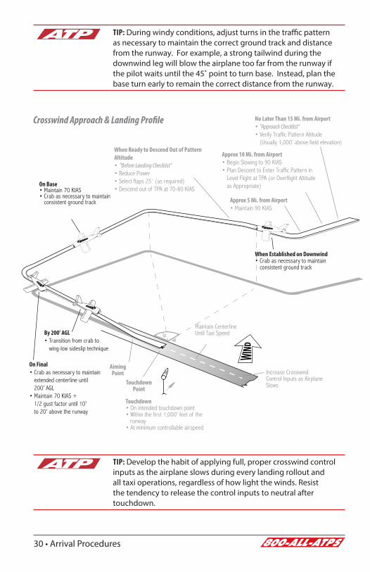
Crosswind Approach & LandingCarefully planned adjustments must be made to the normal approach and landing procedure to safely complete a crosswind approach and landing.
PlanningBefore entering the traffic pattern, brief how your approach and landing will be different by acknowledging the wind direction, crosswind component, planned flap setting, and how your traffic pattern ground track will differ as a result of the winds.
Ground TrackPlan a crab angle on downwind to maintain a uniform distance from the runway. Begin the base turn so the airplane is established on base at the appropriate distance from the runway. Do not allow the winds to blow the airplane off the intended ground track. Turning final, adjust for the winds to not over or undershoot the runway centerline.
Control TechniqueEstablish a crab angle to maintain the proper ground track on final, then transition to the wing-low sideslip technique by no later than 200' AGL and below. Maintain the wing-low technique until touchdown and throughout the landing roll. After landing, increase aileron input into the wind as the airplane slows to prevent the upwind wing from rising, reduce side-loading tendencies on the landing gear, and minimize the risk of roll-over accidents due to the upwind wing lifting.
JudgmentThe demonstrated crosswind component in the PA28 is 17 knots. Regardless of reported winds, if the required bank to maintain drift control is such that full opposite rudder is required to prevent a turn toward the bank, the wind is too strong to safely land the airplane. Select another runway or airport and go-around any time the outcome of an approach or landing becomes uncertain.
30 • Arrival Procedures
TIP: Develop the habit of applying full, proper crosswind control inputs as the airplane slows during every landing rollout and all taxi operations, regardless of how light the winds. Resist the tendency to release the control inputs to neutral after touchdown.
TIP: During windy conditions, adjust turns in the traffic pattern as necessary to maintain the correct ground track and distance from the runway. For example, a strong tailwind during the downwind leg will blow the airplane too far from the runway if the pilot waits until the 45˚ point to turn base. Instead, plan the base turn early to remain the correct distance from the runway.
Crosswind Approach & Landing Profile No Later Than 15 Mi. from Airport• "Approach Checklist"• Verify Traffic Pattern Altitude
(Usually 1,000’ above field elevation)
Touchdown • On intended touchdown point • Within the first 1,000' feet of the runway • At minimum controllable airspeed
Approx 10 Mi. from Airport• Begin Slowing to 90 KIAS• Plan Descent to Enter Traffic Pattern in
Level Flight at TPA (or Overflight Altitude as Appropriate)
Approx 5 Mi. from Airport• Maintain 90 KIAS
When Established on Downwind• Crab as necessary to maintain
consistent ground track
When Ready to Descend Out of Pattern Altitude• "Before Landing Checklist"• Reduce Power• Select flaps 25˚ (as required)• Descend out of TPA at 70-80 KIAS
On Base• Maintain 70 KIAS• Crab as necessary to maintain
consistent ground track
On Final• Crab as necessary to maintain
extended centerline until 200’ AGL
• Maintain 70 KIAS + 1/2 gust factor until 10' to 20' above the runway
90°
45°
AimingPoint
TouchdownPoint
Increase Crosswind Control Inputs as Airplane Slows
By 200' AGL• Transition from crab to
wing-low sideslip technique
Maintain Centerline Until Taxi Speed
Arrival Procedures • 31
When Established on Downwind• Crab as necessary to maintain
consistent ground track
Go-Around ProcedureA go-around procedure must be initiated any time the conditions for a safe approach and landing are not met. Some examples of unsatisfactory approach and landing conditions are:
• Unstable approach path or airspeed.• Improper runway alignment.• Unexpected hazards on the runway or on final.• Anything that jeopardizes a safe approach and landing.
Any time unsafe or unsatisfactory conditions are encountered, a go-around must be immediately executed and another approach and landing should be made under more favorable conditions.
Go-Around / Missed Approach Procedure1. Throttle – full power.2. Carb heat – off.3. Increase pitch to establish climb at 64 KIAS (VX).4. Retract flaps slowly when established at VX and clear of obstacles.5. “After Takeoff Checklist” at pattern altitude or out of 1,000' AGL.
If the go-around or missed approach is due to conflicting traffic, maneuver as necessary during the climb to clear and avoid conflicting traffic.
Rejected or Balked LandingAs a practical guide, a rejected or balked landing occurs when the airplane is very low to the ground and usually occurs after the roundout (flare) has begun. Airspeed may be very low – well below VX or VY in some cases – and the pilot must be very careful to establish and maintain a safe airspeed during the transition to a climb. At slow airspeeds, retracting the flaps too early or abruptly can result in a significant loss of lift. The pilot must also factor in ground effect when initiating a rejected or balked landing close to the ground.
Rejected or Balked Landing Procedure1. Throttle – full power.2. Carb heat – off.3. Accelerate to 60 KIAS (if slower) then;4. Increase pitch to establish climb at 64 KIAS (VX).5. Retract flaps slowly when established at VX and clear of obstacles.6. “After Takeoff Checklist” at pattern altitude or out of 1,000' AGL.

32 • Arrival Procedures
If the rejected landing is due to conflicting traffic, maneuver as necessary during the climb to clear and avoid conflicting traffic.
Precision Approach & LandingATP recommends setting flaps 10° at glideslope intercept for ILS precision approaches. Flaps 10° allows for a stabilized approach to touchdown.
1. Complete the “Approach Checklist” and identify the localizer as early as possible.
2. Slow to 90 KIAS on vectors or when on final approach course inbound.3. Announce “Localizer Alive” when localizer begins moving towards the
center.4. Announce “Glideslope Alive” when glideslope begins moving towards
the center.5. Verify no flags at glideslope intercept altitude and marker.6. ½ dot below glideslope intercept: “Before Landing Checklist.”7. Reduce power, select flaps 10°.8. Descend on glideslope at 80 KIAS.9. Announce at 1,000’ above DA: “1,000 to go.”
10. Announce at 100’ above DA: “100 to go.”11. “Minimums.”12. Runway in sight: descend and slow to 70 KIAS.13. When landing is assured, slow to 66 KIAS until the roundout.
ILS Approach & Landing Profile
“Before Landing Checklist”Reduce PowerSelect Flaps 10˚
Descend at 80 KIAS
90 KIAS
1,000’ Above DA100’ Above DA
DALanding Assured
½ Dot Below
Glideslope Intercept
“1,000 to go”
“100 to go”“Minimums”
Slow to 66 KIAS
Runwayin Sight
Slow to 70 KIAS
Non-Precision Approach & Landing
1. Load approach into the GPS, and select appropriate nav source and frequency.

Arrival Procedures • 33
Within 30 NM of the airport, if flying a GPS approach, the GPS will display “TERM.”
2. When Direct To IAF or on vectors, set the desired course on the CDI.3. Complete the “Approach Checklist.”4. Slow to 90 KIAS when on a published segment of the approach or if on
vectors.
At 2 NM prior to the FAF on a GPS approach, verify green APCH flag on GPS. If no flag appears, DO NOT DESCEND at the FAF.
5. At FAF, complete “Before Landing Checklist” – Flaps 10° – Slow to 80 KIAS.
6. At FAF: start time if required.7. Descend at 400-500 FPM (unless steeper descent required) at 80 KIAS.8. Announce at 100’ above MDA: “100 to go.”9. Increase power 50’ prior to reaching MDA to maintain 80 KIAS
at level off.10. “Minimums.”11. Maintain MDA (plus 50’, minus 0’).12. Runway in sight: descend at predetermined VDP or maintain
MDA to MAP.13. Do not leave MDA until landing can be accomplished using a stabilized
descent angle and normal maneuvers.14. When descending from MDA: Flaps 25° - 70 KIAS.15. When landing assured, slow to 66 KIAS until the roundout.
Non-Precision Approach & Landing Profile
Start Time if Required“Before Landing Checklist”Reduce PowerSelect Flaps 10°
90 KIAS80 KIAS400-500 FPM
80 KIAS100’ Above MDA
MDA(plus 50’, minus 0’)
Leaving MDALanding Assured
FAF
“100 to go”
“Minimums”Slow to 66 KIAS
Select Flaps 25°Stabilized Descent at 70 KIAS

34 • Arrival Procedures
Circling ApproachWhen conducting a circling approach (precision or non-precision), execute the approach with the same speeds at flaps 10° to the published circling minimums.
Maintain circling minimums at 80 KIAS, until in a position from which a normal landing may be made.
When descending from MDA (circling minimums), select flaps 25° and slow to 70 KIAS. Slow to 66 KIAS when landing is assured.
Circling Approach Profile
Maintain 80 KIAS
Leaving MDA
90 KIAS80 KIAS400-500 FPM
100’ Above MDAMDA
FAF
“100 to go”
“Minimums”
Select Flaps 25°Stabilized Descent at 70 KIAS
Landing Assured
Slow to 66 KIAS
Start Time if Required“Before Landing Checklist”Reduce PowerSelect Flaps 10°
Holding1. Slow to 100 KIAS holding speed 3 minutes prior to fix2. Make proper entry3. Report altitude and time at holding fix4. Hold at 100 KIAS, with 1 minute leg to the inbound fix
(unless otherwise specified)

In-Flight Maneuvers • 35
SECTION 5
In-Flight Maneuvers
Required maneuvers for the Commercial Pilot Single-Engine Add-On are performed the same as those for Private Pilot, with two exceptions:
• Commercial steep turns are accomplished with at least 50° of bank.
• Stall recovery at the commercial level is performed at the first indication of an impending stall (e.g., aircraft buffet, stall horn, etc.).
Commercial Pilot Single Engine Add-On completion standards allow for lower tolerances than Private Pilot standards on maneuvers. Refer to the ACS.
Clean Configuration Flow1. Electric fuel pump – on2. Fuel selector – proper tank3. Mixture – enrichen4. Flaps 0°
Landing Configuration Flow1. Electric fuel pump – on2. Fuel selector – proper tank3. Mixture – enrichen4. Flaps 40°

36 • In-Flight Maneuvers
GROUND USE ONLY
PVT Steep Turns Steep turns are to be accomplished above 3,000' AGL. Roll into one coordinated 360˚ turn, then follow with another coordinated 360˚ turn in the opposite direction. Roll into and out of turns at approximately the same rate.
1. Perform two 90° clearing turns 2. 100 KIAS (approx. 2300 RPM), maintain altitude 3. Cruise configuration flow4. Roll into 45° bank5. Maintain altitude and airspeed (+ back pressure, + approx. 1-200 RPM) 6. Roll out ½ bank angle prior to entry heading7. Clear traffic and roll in opposite direction8. Roll out ½ bank angle prior to entry heading 9. "Cruise Checklist"
ACSAirspeed Altitude Bank Heading±10 KIAS ±100' 45° ±5° ±10°
PVT Maneuvering During Slow FlightSlow flight is to be accomplished at an entry altitude that will allow completion above 1,500' AGL. Establish and maintain an airspeed at which any further increase in angle of attack, increase in load factor, or reduction in power would result in a stall warning (e.g., aircraft buffet, stall horn, etc.).
1. Perform two 90° clearing turns2. 1500 RPM (maintain altitude)3. Landing configuration flow4. Maintain altitude – slow to just above stall warning activation
(approximately 50-55 KIAS). 5. Power as required to maintain airspeed and altitude6. Accomplish level flight, climbs, turns, and descents as required without
activating a stall warning (ATP – max 30° bank)
7. Recover – max power/maintain altitude/reduce flaps to 0°8. Accelerate to 64 KIAS (VX)9. "Cruise Checklist"
ACSAirspeed Altitude Bank Heading
+10/-0 KIAS ±100' ±10° ±10°

In-Flight Maneuvers • 37
GROUND USE ONLY
PVT Power-Off StallStalls are to be accomplished at an entry altitude that will allow completion no lower than 1,500' AGL. This maneuver is begun by first establishing a stabilized descent in the landing configuration.
1. Perform two 90° clearing turns2. Approx. 1500 RPM (maintain altitude)3. Landing configuration flow4. Stabilized descent at 66 KIAS5. Throttle idle (slowly)6. Wings level or up to 20° bank as assigned7. Pitch to maintain altitude (slowly), and acknowledge cues of the impending
stall8. At stall/first indication of impending stall (as required) recover –
simultaneously reduce AOA, max power, and level wings9. Slowly retract flaps to 10°
10. Accelerate to 64 KIAS (VX), positive rate11. Retract flaps to 0°
12. "Cruise Checklist"
ACSBank Heading±10°
Not to exceed 20°±10°
PVT Power-On StallStalls are to be accomplished at an entry altitude that will allow completion no lower than 1,500' AGL.
1. Perform two 90° clearing turns2. Approx. 1500 RPM (maintain altitude)3. Clean configuration4. At 70 KIAS, simultaneously increase pitch (slowly) and apply full power.5. Slowly increase pitch to induce stall, and acknowledge cues of the impending
stall6. At stall/first indication of impending stall (as required) recover –
simultaneously reduce AOA, max power, and level wings7. Accelerate to 64 KIAS (VX), positive rate8. "Cruise Checklist"
ACSBank Heading±10°
Not to exceed 20°±10°

38 • In-Flight Maneuvers
GROUND USE ONLY
PVT Emergency DescentDuring a simulated emergency descent, the applicant must be able to recognize situations requiring an emergency descent, such as cockpit smoke and/or fire. Situational awareness, appropriate division of attention, and positive load factors should be maintained during the maneuver and descent.
1. Perform two 90° clearing turns2. Clean configuration flow3. Reduce throttle to idle 4. Initiate turning descent, while clearing for traffic5. Maintain (training) 120 KIAS6. Notify ATC/Traffic as appropriate
COM ChandellesChandelles are to be accomplished at an entry altitude that will allow completion no lower than 1,500' AGL, and consist of one maximum performance climbing turn beginning from straight-and-level flight, and ending at the completion of a precise 180° turn in a wings-level, nose-high attitude at the minimum controllable airspeed.
1. Perform two 90° clearing turns2. 100 KIAS (approx. 2300 RPM), maintain altitude3. Clean configuration flow4. Choose a reference point off wing5. Establish / maintain 30° bank6. Full throttle – increase pitch to attain approx. 10-12° pitch up at 90°
point 1st 90° of turn – Bank = constant 30°, Pitch = increasing to 10-12° pitch up
7. 90° point – maintain pitch, reduce bank angle to attain level flight at 180° point 2nd 90° of turn – Pitch = constant 10-12° pitch up, Bank = decreasing to level flight
8. 180° point – wings level, minimum controllable airspeed 9. Accelerate while maintaining level flight
10. "Cruise Checklist"
ACSAirspeed Heading
Just above stall Rollout at 180° point ±10°
LEVEL FLIGHT, 100 KIAS
30º BANK,10-12º PITCH-UP
LEVEL FLIGHT,MINIMUMCONTROLLABLEAIRSPEED

In-Flight Maneuvers • 39
GROUND USE ONLY
COM Lazy EightsLazy Eights are to be accomplished at an entry altitude that will allow the task to be completed no lower than 1,500' AGL. The applicant is required to maintain coordinated flight throughout the maneuver, with a constant change of pitch and roll rate.
1. Perform two 90° clearing turns2. 100 KIAS (approx. 2300 RPM), maintain altitude3. Clean configuration flow4. Choose a reference point off of the wing5. Simultaneously increase pitch and bank (slowly)6. 45° point – 15° pitch up, 15° bank7. Reduce pitch / increase bank8. 90° point – level pitch, 30° bank - min. speed (5-10 knots above stall)9. Continue reducing pitch and reduce bank
10. 135° point – 15° pitch down, 15° bank11. 180° point – level flight, entry airspeed and altitude12. Repeat in opposite direction13. "Cruise Checklist"
ACS At 180° points:
Airspeed Altitude Heading±10 KIAS ±100' ±10°
90º POINT1. Bank 30 ° (approx.)2. Minimum Speed (5-10 kts above stall)3. Maximum Altitude4. Level Pitch Attitude
ENTRY1. Level Flight2. Maneuvering or Cruise Speed Whichever is Less or Manufacturer’s Recommended Speed.
180º POINT1. Level Flight2. Entry Airspeed3. Altitude Same as Entry Altitude
135º POINT1. Max. Pitch-down (approx. 15º)2. Bank 15º (approx.)
45º POINT1. Max. Pitch-Up (approx. 15º)2. Bank 15º (approx.)

40 • In-Flight Maneuvers
GROUND USE ONLY
COM Eights On PylonsEights on Pylons are to be accomplished at the appropriate pivotal altitude (groundspeed2/11.3), governed by the aircraft's groundspeed. The applicant is required to maintain coordinated flight while flying a figure eight pattern which holds the selected pylons using the appropriate pivotal altitude. At the steepest point, the angle of bank should be approximately 30-40°.
1. Enter pivotal altitude (approx. 900’ AGL at 100 KIAS, approx. 2300 RPM)2. Perform two 90° clearing turns3. Clean configuration flow4. Select two pylons to allow for minimal time spent wings level
between the two5. Enter maneuver on a 45° midpoint downwind6. Apply appropriate pitch corrections to compensate for changes in
groundspeed and to maintain line of sight reference with the pylon (pitch forward if point moves toward nose and pitch back if point moves toward tail)
7. Begin rollout to allow the airplane to proceed diagonally between the pylons at a 45° angle
8. Begin second turn in the opposite direction of the first9. Exit maneuver on entry heading
10. "Cruise Checklist"
PivotalAltitude
High GroundspeedHigh Pivotal Altitude
LowestGroundspeedLowest Pivotal
Altitude
Closest to Pylon
Entry
Pylon
PivotalAltitude
High GroundspeedHigh Pivotal Altitude
LowestGroundspeedLowest Pivotal
Altitude
Closest to Pylon
Entry
Pylon
PivotalAltitude
High GroundspeedHigh Pivotal Altitude
LowestGroundspeedLowest Pivotal
Altitude
Closest to Pylon
Entry
Pylon
NOTE: The wing tip should be pointing at the pylons throughout the turns.

In-Flight Maneuvers • 41
GROUND USE ONLY
COM Steep Spirals
1. Altitude – at least 3,000’ AGL2. Perform two 90° clearing turns3. 90 KIAS (approx. 1800 RPM), maintain altitude4. Clean configuration flow5. Choose visual reference point6. Reduce throttle to idle7. Track at least three constant radius circles around reference point8. Airspeed – constant9. Bank angle – adjust for winds,
not to exceed 60°10. Clear engine once every 360°
turn11. Recover – roll out on specified
heading (or visual reference)12. "Cruise Checklist"
ACSAirspeed Heading±10 KIAS Rollout towards specified
heading or point±10°
COM Accelerated StallAccelerated stalls are accomplished at an altitude that allows completion no lower than 3,000' AGL. Transition smoothly from cruise attitude to a bank angle of 45°, maintaining coordinated turning flight, while increasing elevator back pressure steadily to induce an impending stall.
1. Perform two 90° clearing turns2. Clean configuration flow3. Slow to 80 KIAS4. Slowly reduce power to idle5. Establish a coordinated 45° bank turn6. Maintain altitude to induce an impending stall7. Recover at the first indication of an impending stall (e.g., aircraft buffet,
stall horn, etc.)8. Reduce AOA, level wings, and set max power9. “Cruise Checklist”

42 • In-Flight Maneuvers
GROUND USE ONLY
CFI Secondary Stall (Power-On)
Secondary Stalls are to be accomplished above 3,000' AGL. The purpose is to demonstrate the effect of attempting to hasten the completion of a stall recovery before the airplane has regained sufficient flying speed. Demonstrate and simultaneously explain secondary stalls from an instructional standpoint.
1. Perform two 90° clearing turns2. 1500 RPM (maintain altitude)3. Clean configuration flow4. At 60 KIAS, simultaneously increase pitch (slowly) and apply full power5. Increase pitch attitude to induce stall6. At stall, recover – simultaneously reduce AOA, max power, and level
wings7. When stall horn silences, increase pitch to induce a secondary stall8. At stall, recover – simultaneously reduce AOA, max power, and level
wings9. “Cruise Checklist”
CFI Secondary Stall (Power-Off)
Secondary Stalls are to be accomplished above 3,000' AGL. The purpose is to demonstrate the effect of attempting to hasten the completion of a stall recovery before the airplane has regained sufficient flying speed. Demonstrate and simultaneously explain secondary stalls from an instructional standpoint.
1. Perform two 90° clearing turns2. 1500 RPM (maintain altitude)3. Landing configuration flow4. Stabilized descent at 66 KIAS5. Throttle idle (slowly)6. Maintain altitude to induce stall7. At stall, recover – simultaneously reduce AOA and level wings (do not
add power)8. When stall horn silences, increase pitch to induce a secondary stall9. At stall, recover – simultaneously reduce AOA, max power, and level
wings10. Slowly retract flaps to 10˚11. Accelerate to 64 KIAS (VX), positive rate12. Retract flaps to 0˚13. “Cruise Checklist”

In-Flight Maneuvers • 43
GROUND USE ONLY
CFI Elevator Trim StallElevator Trim Stalls are to be accomplished above 3,000' AGL. The purpose is to demonstrate what can happen when full power is applied for a go-around and positive control of the airplane is not maintained. Demonstrate and simultaneously explain elevator trim stalls from an instructional standpoint.
1. Perform two 90° clearing turns2. 1500 RPM (maintain altitude)3. Landing configuration flow4. Trim for stabilized descent at 66 KIAS5. Apply full power (slowly)6. Allow the nose to rise and turn left 7. When stall is approaching (high AOA) recover – simultaneously reduce
AOA, max power, and level wings8. Adjust trim while accelerating to VX
9. Slowly retract flaps to 10°10. Accelerate to 64 KIAS (VX), positive rate11. Retract flaps to 0° 12. “Cruise Checklist”

44 • In-Flight Maneuvers
GROUND USE ONLY
CFI Cross-Control StallCross-Control Stalls are to be accomplished above 3,000' AGL. The purpose is to demonstrate the effect of improper control technique and to emphasize the importance of using coordinated control pressures whenever making turns. This demonstration shows what can happen during a poorly executed base-to-final turn where too much rudder is applied in the direction of the turn. Demonstrate and simultaneously explain cross-control stalls from an instructional standpoint.
CAUTION: Cross-control stalls can lead to loss of control or spins. Recover at the first indication of the stall, and review spin recovery procedures.
1. Perform two 90° clearing turns2. 1500 RPM (maintain altitude)3. Clean configuration flow4. Stabilized descent at 66 KIAS5. Establish a 30˚ banked turn6. Smoothly apply excessive rudder pressure in the direction of the turn 7. As rudder pressure increases, opposite aileron will be necessary to
maintain constant bank angle 8. Increase aft elevator pressure9. At first indication of stall, recover – simultaneously reduce AOA, max
power, and level wings10. “Cruise Checklist”

Oral Review • 45
SECTION 6
Oral Review
Lost Comm Procedure (FAR 91.185)If in VFR conditions, or if VFR conditions are encountered, squawk 7600, remain VFR and land as soon as practicable.
If in IFR conditions, squawk 7600 and fly:
Route(First that applies)
Altitude (Whichever is highest until descent is required for landing)
Assigned Minimum IFR Altitude
Vectored Expected
Expected Assigned
Filed
FAR Review1. To maintain instrument currency, a pilot must have made six
approaches and demonstrated proper holding procedures as well as intercepting and tracking courses through the use of navigational electronic systems in the last six months.
2. An alternate is not required if your destination has an instrument approach procedure, and the weather at your destination is forecast to be at least a 2,000' ceiling and visibility of at least three miles. The forecast must be from one hour before to one hour after your estimated time of arrival.
3. If an alternate airport is needed, forecasted weather at ETA must be at least 600' ceiling and 2 miles visibility for a precision approach; an alternate airport that offers only a non-precision approach must be at least 800' ceiling and 2 miles visibility.
4. Reserve fuel of 45 minutes is required for IFR flights; 30 minutes for VFR day flights; and 45 minutes for VFR night flights. This reserve is required in addition to the fuel required to fly to your destination and alternate.

46 • Oral Review
5. VOR limits: 4 degrees for VOT, ground checkpoint and dual check. 6 degrees for an airborne check.
6. VOR equipment must be checked every 30 days.
7. Transponders must be checked every 24 calendar months.
8. Pitot static systems must be checked every 24 calendar months.
9. ELT equipment must be checked every 12 months, after half of the battery life, or after 1 hour of cumulative use.
10. An aircraft used for hire must have a 100 hour and an annual inspection.
11. In order to descend below the DA or MDA, all of the following conditions must exist:
A. The required flight visibility is met.B. The aircraft is in a normal position to land.C. (1) The runway environment is in sight – descend to land.
(2) Approach lights in sight – descend to 100' above touch down zone until runway environment is in sight. (3) Descend and land if red terminating bars or red side row bars are in sight.
12. The minimum equipment list includes a list of equipment that may be inoperative for a particular phase of flight. If not required to have a MEL, comply with the minimum equipment prescribed by the FAR’s.
13. Standard Traffic Pattern Altitude (TPA) is 1,000' AGL.
Answer The Following Sample Oral Questions Prior To Arriving For Training1. Recite the v-speeds.
2. What is the maximum demonstrated crosswind component?
3. Describe the PA-28-181 engine.A. How many cylinders?B. Who is the manufacturer?C. What is the horsepower rating?D. Does it have fuel injectors or a carburetor? E. Is the engine turbo-charged or normally aspirated?F. How are the cylinders arranged?G. How is ignition provided?H. What are the minimum and maximum oil capacities?

Oral Review • 47
4. Describe the propeller system.A. Who makes the propellers?B. How is propeller RPM adjusted?C. Define fixed pitch.
5. Describe the electrical system.
6. What are the indications of a failed alternator?
7. Will the engine continue to run with the alternator and battery master switches turned off?
8. Describe the stall warning system.
9. Describe the fuel system.
10. Explain how to change fuel tanks in cruise flight.
11. Describe the landing gear system.A. How is steering accomplished on the ground?B. What is the range of travel on the nose wheel?
12. What type of braking system is used by the Archer? Where is the brake fluid reservoir?
13. What type of flaps does the Archer have?A. What are the flap settings on the Archer?
14. What are the maximum taxi, takeoff, and landing weights?
15. What is the maximum baggage capacity?
16. Define VX and VY.
17. What aircraft equipment checks are required under FAR Part 91?
18. What documents are required to be on the aircraft?
19. Explain lost communications procedures.
20. Explain the pitot-static system.A. Does the PA-28 have an alternate static source? If so, how is it
activated and what actions are necessary to acquire the most accurate reading?
B. What instruments are pitot-static?C. Where is the pitot-static port located?

48 • Oral Review
21. What is the fuel capacity? How many gallons are unusable?
22. What grade fuel is to be used in the PA-28?
23. How many fuel pumps are on the aircraft?
24. When is the electric fuel pump to be used?
25. What are the various positions on the fuel selector control?
26. In the event of an electrical failure, what pilot actions are necessary to ensure continued operation of the standby attitude indicator?
27. If the standby power button on the attitude indicator is not pressed within one minute of electrical failure, what will happen?
28. How do you determine a standard rate turn on an aircraft with a G500 system?
29. In the event of an AHRS failure, which indications will no longer be displayed on the PFD? Which indications will still be visible on the PFD?
30. Which approaches can be accomplished with an AHRS failure?
31. What instrument approaches are available with the PFD inoperative? With the MFD inoperative? With a total PFD/MFD failure?
32. How long does the internal battery last when providing power to the standby attitude indicator? With the loss of the ADC, which lost instrument does not have a backup? What should you do to compensate for the lack of information?

172 & Archer Differences • 49
APPENDIX A
172 & Archer Differences172 (180 HP R&S Models) PA-28
Remains in “BOTH” throughout flight unless notable fuel imbalance encountered.
Cessna 172 Training Supplement page 4
Fuel Selector
Must be switched to appropriate tank (L or R) every 30 minutes in flight, or when appropriate.
Timer can be set on GNS 430 and transponder. POH does not provide a limitation on fuel imbalance.
See the Piper Archer Training Supplement, page 4, for guidance and timing for fuel selector changes.
Flaps 10 on downwind, 20 on base
Cessna 172 Training Supplement pages 23 & 24
Landing Profile
Flaps 25 abeam as part of before landing checklist
Piper Archer Training Supplement page 25
GNS 430 have removable NavData cards.
G1000 have Internal memory and must be updated with external SD card. Installed SD cards are Terrain database, are specific to the equipment by serial number and must not be removed. See guidance atpintra.net/navdata
Terrain data is not updated.
Database Updates
GNS 430 have removable NavData cards.
Do not remove the SD card from G500. The G500 SD card is not to be updated. NavData information displayed on the G500 resides on the GNS 430 card.
See guidance atpintra.net/navdata
Terrain data is not updated.
Climb Performance
Noticeably lower. May affect ability to comply with DP
Landing Requires much less flare, closer to a Seminole
Fuel Injected
Cessna 172 Training Supplement page 3Fuel System
Carbureted. Be aware of signs of carb ice.
Piper Archer Training Supplement page 1
13 sumps
Cessna 172 Training Supplement page 4
3 sumps
Confirm closed and not leaking after sumping
Dark when off, lit when on Pitot Heat Annunciator
“Pitot Heat Off/Inop” lit by default, goes dark when on
Cessna 172 Training Supplement page 10 V Speeds Piper Archer Training Supplement page 13
40 (Bottom of white arc) Vso 45 (Bottom of white line)
55 Vr 60
62 Vx 64
74 Vy 76
90 (1900 lbs) Va 89 (1634 lbs)
105 (2550 lbs) Va 113 (2550 lbs)
110 (10 degrees)
85 (20-30 degrees)
(Top of white arc)
Vfe 102 (Top of white line)
129 (Top of green arc) Vno 125 (Top of green line)
163 (Red line) Vne 154 (Red line)

50 • 172 & Archer Differences
1690 BEW 1640
2558 Max Ramp Weight 2558
120 Max Baggage Weight 200
2550 Max TOW 2550
55 Fuel Capacity 50
53 (Usable Fuel) 48
10 GPH Approximate Fuel Burn 10 GPH
Flaps 10
Cessna 172 Training Supplement page 14Short Field
Takeoff
Flaps 25
Piper Archer Training Supplement page 17
Flaps 10
Cessna 172 Training Supplement page 15Soft Field Takeoff
Flaps 25
Piper Archer Training Supplement page 18
62 Short Field Approach Speed 66
General Rudder Trim Installed
Stall horn tested during preflight
Step only on non-skid surface when entering & exiting aircraft.
Do not lean or hang on door, hinges will bend or break easily.
Most performance charts displayed as a table
Most performance charts displayed as graphs
Electrically actuated; 0°, 10°, 20° & 30° FlapsManual; 0°, 10°, 25° & 40°
Piper Archer Training Supplement page 3
When M BUS VOLTS falls below 20 volts, the standby battery system will automatically supply electrical power to the essential bus for at least 30 minutes.
(172S NAV III Manual, pg 3-17)
Standby Power
The Standby Attitude Indicator will operate for approximately one hour with the internal battery, depending on battery condition at the time of power failure.
(Piper Archer III Manual, pg 9-141)
Piper Archer Training Supplement page 8
Altimeter & Airspeed Indicator - Pitot Static
Attitude Indicator - Vacuum
Standby Instruments
Altimeter & Airspeed Indicator - Pitot Static
Attitude Indicator - Standby Battery
Piper Archer Training Supplement pages 8 & 9
(55 Gallon Fuel Capacity) Approx 5.5 hrs with 45 Minute Reserve
Endurance Profile Cessna 172S NAV III - Model Years 2008+ Manual, page 5-23
Endurance @ 55% Power(Note: Can be affected
considerably by altitude, leaning,
power setting, etc.)
Approx 4.5 hrs with 45 Minute Reserve
Endurance chart Piper Archer III Manual, page 5-28


Pilot Job Placement Thru
ATPFlightSchool.com
Airline Career Pilot Program
Tuition Reimbursement Programs
Type Rating Programs
Airline Transport Pilot Certification Training Program
Aircraft Dispatcher Training
The Most Respected Name in Pilot Certification
450+PLACEMENTS
Over 450 airline placements in the past 12 months – more than any other flight school.
7k+GRADUATESATP has consistently
trained more than 7,000 pilots for certification at exactly the advertised
price.
100%FINANCING
Full financing available. Only ATP offers
financing solutions for successful career
training.
30YEARS
ATP has provided professional flight training for over 30
years.