Atmel AVR1619: XMEGA-B1 Xplained...
13
Atmel AVR1619: XMEGA-B1 Xplained Demonstration Features • Atmel ® ATxmega128B1 • Atmel XMEGA ® -B1 Xplained kit compatible • On-board LCD display • USB 2.0 Full speed composite device - Mass Storage interface with on-board Atmel DataFlash ® - Generic HID interface for host application data exchange • On-board sensors measurements 1 Introduction This application note presents the default firmware shipped within the XMEGA-B1 Xplained kit that demonstrates all the main capabilities of this kit. Using the Atmel AVR ® XMEGA B devices makes USB and LCD easy to implement and to use. This application note presents a USB composite demonstration application acting both as a USB mass-storage device and a USB generic HID communication device. The USB mass storage interface allows accessing the on-board DataFlash whereas the generic HID interface allows the kit to communicate with a PC application. This application performs on-board sensors (light, temperature, voltages) and at the same time displays the results using the on-board LCD and transmits the measurements results to a PC application using USB. 8-bit Atmel Microcontrollers Application Note Rev. 8449A-AVR-10/11
-
Upload
nguyentruc -
Category
Documents
-
view
222 -
download
0
Transcript of Atmel AVR1619: XMEGA-B1 Xplained...

Atmel AVR1619: XMEGA-B1 Xplained Demonstration
Features • Atmel® ATxmega128B1 • Atmel XMEGA®-B1 Xplained kit compatible • On-board LCD display • USB 2.0 Full speed composite device
- Mass Storage interface with on-board Atmel DataFlash® - Generic HID interface for host application data exchange
• On-board sensors measurements
1 Introduction This application note presents the default firmware shipped within the XMEGA-B1 Xplained kit that demonstrates all the main capabilities of this kit.
Using the Atmel AVR® XMEGA B devices makes USB and LCD easy to implement and to use. This application note presents a USB composite demonstration application acting both as a USB mass-storage device and a USB generic HID communication device.
The USB mass storage interface allows accessing the on-board DataFlash whereas the generic HID interface allows the kit to communicate with a PC application.
This application performs on-board sensors (light, temperature, voltages) and at the same time displays the results using the on-board LCD and transmits the measurements results to a PC application using USB.
8-bit Atmel Microcontrollers Application Note
Rev. 8449A-AVR-10/11

2 Atmel AVR1619 8449A-AVR-10/11
2 Environment The demonstration consists of an embedded application for the Atmel ATxmega128B1 (this will be called “firmware” in the rest of this document) and a PC host application (running on Windows® XP, Windows Vista®, or Windows 7).
The host application communicates with the Atmel XMEGA-B1 Xplained using the USB generic HID interface handled by the firmware. The PC host application allows retrieving the on-board sensors measurements (NTC, light sensor, external and potentiometer voltages), touch buttons status, and control the LEDs from the XMEGA-B1 Xplained (please refer to Chapter 6 about related documentation to access the ‘XMEGA-B1 Xplained Hardware user guide’).
The demonstration is designed for XMEGA-B1 Xplained kit with ATxmega128B1.
The default firmware is configured to target ATxmega128B1 revision B and higher. A specific build of this application is required for ATxmega128B1 revision A (Section 3.2 gives information about how to rebuild the application for revision A).
ATxmega128B1 firmware for XMEGA-B1 Xplained kit
PC Host application:- Get on-board sensor
measurement- Control the XMEGA-B1 Xplained

Atmel AVR1619
38449A-AVR-10/11
3 Firmware setup Out of the box, the Atmel XMEGA-B1 Xplained kit is pre-programmed with this default firmware. However, if this default firmware is erased or modified, it is possible to recover the original firmware using the hex file included within the zip file attached to this application note.
3.1 Downloading the firmware If the on-chip Atmel ATxmega128B1 firmware needs to be downloaded into the XMEGA-B1 Xplained kit, this could be achieved by using one of the following methods:
• Using the ATxmega128B1 on-chip DFU bootloader and FLIP (please refer to Atmel AVR1619 application note about using the on-chip DFU bootloader with ATxmega128B1)
• Using the Atmel AVR Studio® 5 and the regular Atmel AVR tools like JTAGICE3, AVR ONE!, or JTAGICE mkII (please refer to the on-line help of AVR Studio 5 about how to use it for part programming)
3.2 Rebuilding the firmware It is also possible to rebuild this application from its sources files located in the Atmel AVR Software Framework (ASF, www.atmel.com/asf) and AVR Studio 5 (www.atmel.com/avrstudio5). This application is available as a pre-configured example available from AVR Studio 5 called “Demo Application for XMEGA-B1 Xplained”.
3.2.1 Atmel ATxmega128B1 revision A considerations
As specified in Chapter 2, the default firmware configuration targets an ATxmega128B1 revision B device. The firmware can be rebuilt for revision A by adding the “CONFIG_XMEGA_128B1_REVA” define to the list of pre-defined symbols in the project options.

4 Atmel AVR1619 8449A-AVR-10/11
If the firmware loaded into the Atmel XMEGA-B1 Xplained does not match the ATxmega128B1 revision, the on-board LCD will display a “REV ERR” message.

Atmel AVR1619
58449A-AVR-10/11
4 Host application setup The host application called ‘XMEGA-B1 Xplained demonstration’ is optional, but it allows controlling and getting information from the Atmel XMEGA-B1 Xplained by using USB generic HID interface.
The host application setup can be found in the zip file attached to this application note. To install the application, follow the installation wizard started from the ‘setup.exe’ file.
Figure 4-1. Host application installation wizard.

6 Atmel AVR1619 8449A-AVR-10/11
5 Running the demonstration
5.1 Connecting the Atmel XMEGA-B1 Xplained to USB When connecting to the USB host computer for the first time, the firmware will enumerate as a composite device with two USB interfaces.
The operating system will install the new USB devices by itself (no specific driver is needed for both mass storage and generic HID interfaces). Once the new hardware installation process is complete, the XMEGA-B1 Xplained kit is visible in three different locations within the device manager as shown in the figure below.
Figure 5-1. Device manager view.
5.2 Using the XMEGA-B1 Xplained demonstration firmware The demonstration firmware can be used in a stand alone mode (meaning without the PC host application running).
In that case the application displays the selected sensor value using the on-board LCD glass of the XMEGA-B1 Xplained. The capacitive touch buttons CS0…CS3 can be used to select which sensor should be displayed.
• CS0 displays the ADC value of the light sensor (raw value of the ADC conversion) • CS1 displays the temperature value based on the on-board NTC (in °C) • CS2 displays the potentiometer voltage (in mV) • CS3 displays the external voltage input (in mV)

Atmel AVR1619
78449A-AVR-10/11
Figure 5-2. Atmel XMEGA-B1 Xplained running the application.
5.2.1 Using the USB mass storage interface
The USB mass storage interface allows accessing the on-board DataFlash of XMEGA-B1 Xplained as a regular USB thumb drive.
Prior to use this drive, the operating system will ask to format it.
Figure 5-3. Formatting the mass storage drive.
The drive capacity is automatically detected as the on-board DataFlash size, meaning 8Mbytes.
Figure 5-4. Format properties for mass storage drive.
Once properly formatted, the drive can be used to store and read files.
8 Atmel AVR1619 8449A-AVR-10/11
5.2.2 Using the USB generic HID interface
This USB interface offers the capability to control and get the following information from the Atmel XMEGA-B1 Xplained:
• Retrieve on-board sensors measurements • Get touch buttons status • Get information about the connected firmware • Adjust on-board LCD contrast and backlight level • Control on-board LEDs • Display user input text strings or numeric values on the LCD The generic HID interface is accessible using the PC host application previously installed. Once the application is started it displays a control panel with the same look and feel as the XMEGA-B1 Xplained kit:
Figure 5-5. Host application main view.
5.2.2.1 Connecting the host application to the XMEGA-B1 Xplained kit
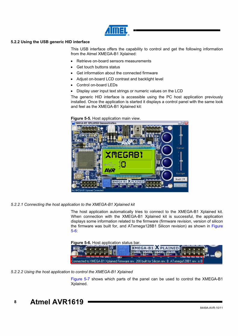
The host application automatically tries to connect to the XMEGA-B1 Xplained kit. When connection with the XMEGA-B1 Xplained kit is successful, the application displays some information related to the firmware (firmware revision, version of silicon the firmware was built for, and ATxmega128B1 Silicon revision) as shown in Figure 5-6:
Figure 5-6. Host application status bar.
5.2.2.2 Using the host application to control the XMEGA-B1 Xplained
Figure 5-7 shows which parts of the panel can be used to control the XMEGA-B1 Xplained.

Atmel AVR1619
98449A-AVR-10/11
Figure 5-7. Host application input controls.
• The vertical cursor to the right called ‘Contrast’ and ‘Backlight’ allows adjusting the
on-board LCD display • The four LEDs on the bottom can be activated so that it toggles the on-board
LEDs • The LCD text field can be selected and a user message can be input. This user
text string will be displayed for a few seconds both on the on-board LCD and on the host application
• Like the text field, the LCD numeric field can be used to display a numeric value

10 Atmel AVR1619 8449A-AVR-10/11
5.2.3 Using the host application to display information
The figure below shows what parts of the panel can be used to display information coming from the Atmel XMEGA-B1 Xplained.
Figure 5-8. Host application output controls.
• The touch buttons display on the host application reflects the activation status of
CS0...CS3 on the XMEGA-B1 Xplained • The four LEDs on the bottom show the current status of the LEDs of XMEGA-B1
Xplained • The LCD text field displays the name of the selected sensor and the LCD numeric
field displays the value of this sensor. The display on the host application is thus similar to the on-board LCD of the XMEGA-B1 explained
• The ‘Graph’ button shows another panel where the real-time captured values of the on-board sensors are displayed within real-time graphs. Please note that this real-time panel can be closed pressing this button once again
Figure 5-9. Host application graph window.

Atmel AVR1619
118449A-AVR-10/11
6 Related documentation • Atmel AVR1912: XMEGA-B1 Xplained Hardware user guide
http://www.atmel.com/dyn/resources/prod_documents/doc8397.pdf
• Atmel AVR1916: USB DFU bootloader for XMEGA http://www.atmel.com/dyn/resources/prod_documents/doc8429.pdf
• Atmel FLIP http://www.atmel.com/dyn/products/tools_card.asp?tool_id=3886
• Atmel AVR Software Framework http://www.atmel.com/asf
• Atmel AVR XMEGA B Manual http://www.atmel.com/dyn/resources/prod_documents/doc8291.pdf
• Atmel AVR Studio 5.0 http://www.atmel.com/dyn/products/tools_card.asp?tool_id=17212
• Atmel AVR4900: ASF - USB Device stack http://www.atmel.com/dyn/resources/prod_documents/doc8360.pdf

12 Atmel AVR1619 8449A-AVR-10/11
7 Table of contents Features............................................................................................... 1 1 Introduction ...................................................................................... 1 2 Environment ..................................................................................... 2 3 Firmware setup ................................................................................ 3
3.1 Downloading the firmware................................................................................... 3 3.2 Rebuilding the firmware....................................................................................... 3
3.2.1 Atmel ATxmega128B1 revision A considerations...................................................... 3 4 Host application setup..................................................................... 5 5 Running the demonstration ............................................................ 6
5.1 Connecting the Atmel XMEGA-B1 Xplained to USB........................................... 6 5.2 Using the XMEGA-B1 Xplained demonstration firmware.................................... 6
5.2.1 Using the USB mass storage interface...................................................................... 7 5.2.2 Using the USB generic HID interface ........................................................................ 8 5.2.3 Using the host application to display information..................................................... 10
6 Related documentation ................................................................. 11 7 Table of contents ........................................................................... 12

8449A-AVR-10/11
Atmel Corporation 2325 Orchard Parkway San Jose, CA 95131 USA Tel: (+1)(408) 441-0311 Fax: (+1)(408) 487-2600 www.atmel.com
Atmel Asia Limited Unit 01-5 & 16, 19F BEA Tower, Milennium City 5 418 Kwun Tong Road Kwun Tong, Kowloon HONG KONG Tel: (+852) 2245-6100 Fax: (+852) 2722-1369
Atmel Munich GmbH Business Campus Parkring 4 D-85748 Garching b. Munich GERMANY Tel: (+49) 89-31970-0 Fax: (+49) 89-3194621
Atmel Japan 16F, Shin Osaki Kangyo Bldg. 1-6-4 Osaki Shinagawa-ku Tokyo 104-0032 JAPAN Tel: (+81) 3-6417-0300 Fax: (+81) 3-6417-0370
© 2011 Atmel Corporation. All rights reserved.
Atmel®, Atmel logo and combinations thereof, AVR®, AVR Studio®, DataFlash®, XMEGA®, and others are registered trademarks or trademarks of Atmel Corporation or its subsidiaries. Windows® and others are registered trademarks or trademarks of Microsoft Corporation in U.S. and or other countries. Other terms and product names may be trademarks of others. Disclaimer: The information in this document is provided in connection with Atmel products. No license, express or implied, by estoppel or otherwise, to any intellectual property right is granted by this document or in connection with the sale of Atmel products. EXCEPT AS SET FORTH IN THE ATMEL TERMS AND CONDITIONS OF SALES LOCATED ON THE ATMEL WEBSITE, ATMEL ASSUMES NO LIABILITY WHATSOEVER AND DISCLAIMS ANY EXPRESS, IMPLIED OR STATUTORY WARRANTY RELATING TO ITS PRODUCTS INCLUDING, BUT NOT LIMITED TO, THE IMPLIED WARRANTY OF MERCHANTABILITY, FITNESS FOR A PARTICULAR PURPOSE, OR NON-INFRINGEMENT. IN NO EVENT SHALL ATMEL BE LIABLE FOR ANY DIRECT, INDIRECT, CONSEQUENTIAL, PUNITIVE, SPECIAL OR INCIDENTAL DAMAGES (INCLUDING, WITHOUT LIMITATION, DAMAGES FOR LOSS AND PROFITS, BUSINESS INTERRUPTION, OR LOSS OF INFORMATION) ARISING OUT OF THE USE OR INABILITY TO USE THIS DOCUMENT, EVEN IF ATMEL HAS BEEN ADVISED OF THE POSSIBILITY OF SUCH DAMAGES. Atmel makes no representations or warranties with respect to the accuracy or completeness of the contents of this document and reserves the right to make changes to specifications and product descriptions at any time without notice. Atmel does not make any commitment to update the information contained herein. Unless specifically provided otherwise, Atmel products are not suitable for, and shall not be used in, automotive applications. Atmel products are not intended, authorized, or warranted for use as components in applications intended to support or sustain life.
![Atmel AVR XMEGA B Manual - Microchip Technologyww1.microchip.com/...8-and-16-bit-AVR-Microcontrollers-XMEGA-B_M… · XMEGA B MANUAL. XMEGA B [MANUAL] 2 Atmel-8291C-AVR-XMEGA B -09/2014](https://static.fdocuments.us/doc/165x107/5b76f9aa7f8b9ade6f8c05a8/atmel-avr-xmega-b-manual-microchip-xmega-b-manual-xmega-b-manual-2-atmel-8291c-avr-xmega.jpg)


![Atmel AVR XMEGA C Manual - Microchip Technology · 2017. 5. 5. · XMEGA C [MANUAL] 3 Atmel-8465H-AVR-XMEGA C-12/2014 Atmel-8465H-AVR-XMEGA C-Datasheet_12/2014 2. Overview The AVR](https://static.fdocuments.us/doc/165x107/6111be10dc2737184a43a022/atmel-avr-xmega-c-manual-microchip-technology-2017-5-5-xmega-c-manual-3.jpg)